edition 1.2, from serial no. 80239- edition 1, from serial ...metrocompactorwest.com/si 5040...
TRANSCRIPT
Edition 1, From serial no. 73963- Publ. no 4872225-00S
SE/GB/DE/FR/ESSP 5040 std, 2008-10
ReservdelslistaSpare part listErsatzteillisteListe de piéces détachéesLista de repuestos
5040 (std)
OrwakEdition 1, From serial no. 80531
Publ. no 4871555-00S SE/GB/DE/FR/ESSI 3610, 2008-10
3105
OrwakOrwakOrwak
5040 (std)
with service instructions
Edition 1.2, From serial no. 80239- Publ. no 4872225-00S
SE/GB/DE/FR/ESSI 5040 std, 2009-11

2
TABLE OF CONTENTSINNEHÅLLSFÖRTECKNING
RESERVDELSKATALOG SPARE PARTS LIST
Behållare Chamber 4-5Pressenhet Power head 6-7Pressplatta Press plate 8-9Pressenhet Press unit 10-11Givare Switch 12-13 Ellåda Electrical box 14-17Elschema Electrical diagram 18-23Hydraulschema Hydraulic diagram 24
5040
SERVICE INSTRUCTIONS Check list 25 Location of electrical components 26-27 Function description 28-30 Power pack 30 PLC-unit 32-
3
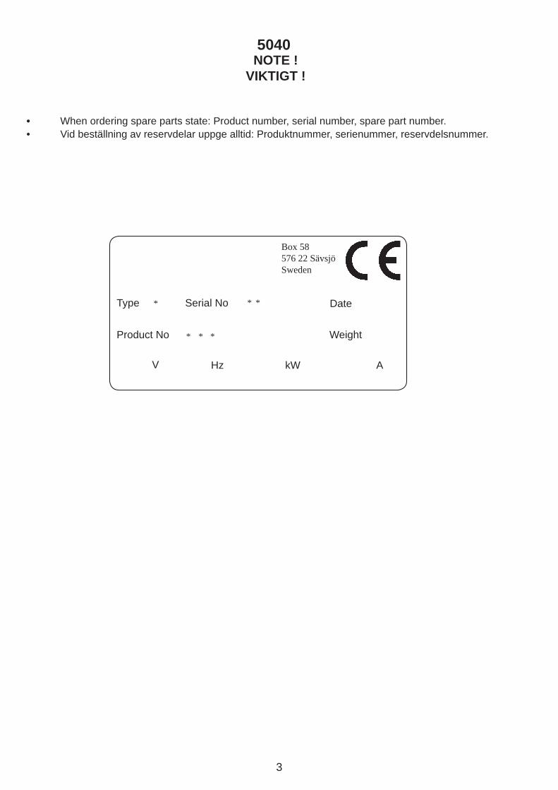
• When ordering spare parts state: Product number, serial number, spare part number. • Vid beställning av reservdelar uppge alltid: Produktnummer, serienummer, reservdelsnummer.
Box 58576 22 SävsjöSweden
Type Serial No
Product No
Date
V
Weight
Hz kW A
* * *
***
NOTE ! VIKTIGT !
5040
4
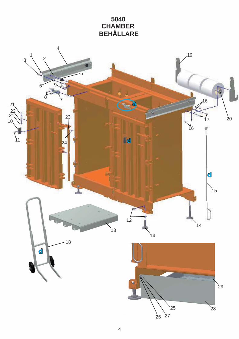
CHAMBER BEHÅLLARE
123
4
5
10
21
23
24
2122
16
78
9
11
1214
14
15
19
20
16
16
17
18
13
29
2827
25
26
5040
aa
dd
dd
dd
5
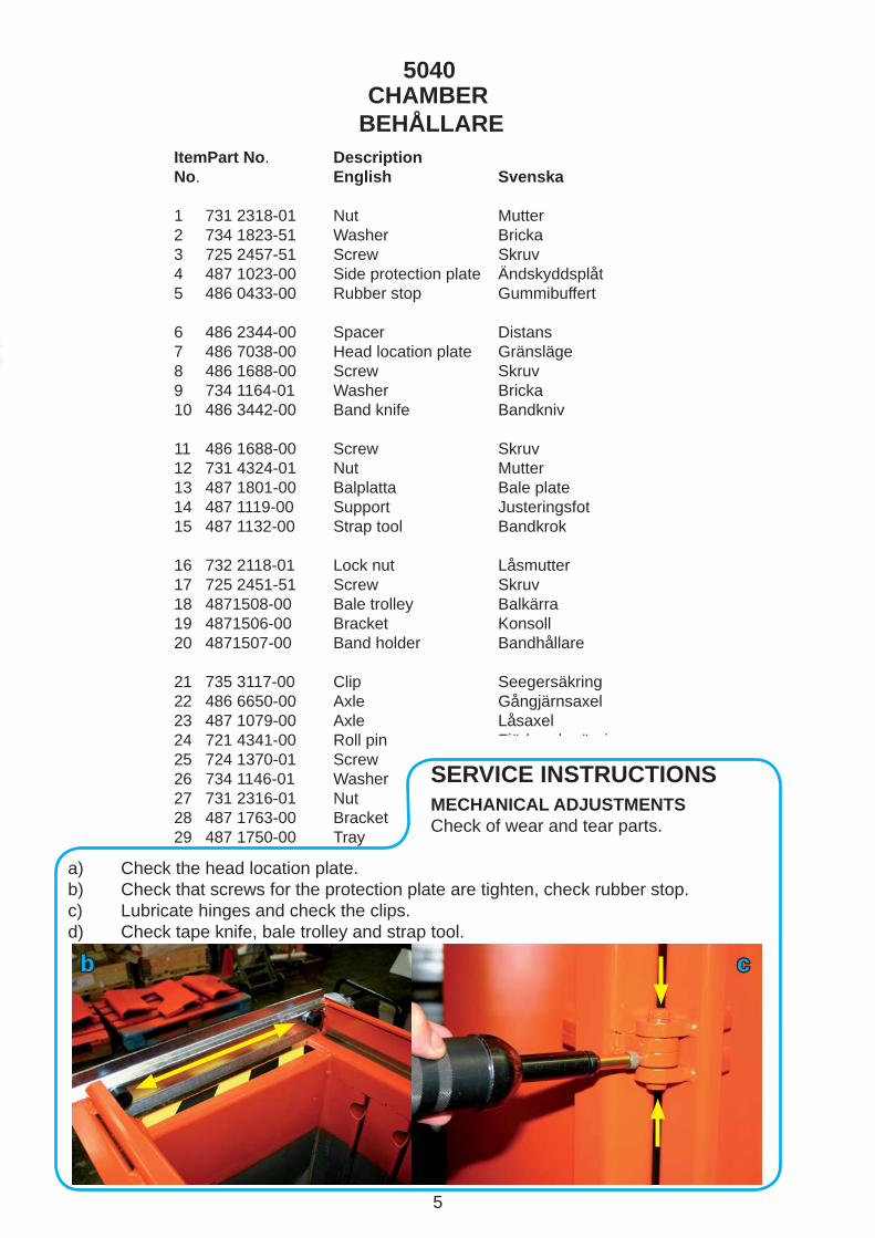
CHAMBER BEHÅLLARE
ItemPart No. DescriptionNo. English Svenska
11 731 2318-01 Nut Mutter 2 734 1823-51 Washer Bricka 3 725 2457-51 Screw Skruv 4 487 1023-00 Side protection plate Ändskyddsplåt 5 486 0433-00 Rubber stop Gummibuffert 6 486 2344-00 Spacer Distans 7 486 7038-00 Head location plate Gränsläge 8 486 1688-00 Screw Skruv 9 734 1164-01 Washer Bricka 10 486 3442-00 Band knife Bandkniv
11 486 1688-00 Screw Skruv 12 731 4324-01 Nut Mutter 13 487 1801-00 Balplatta Bale plate14 487 1119-00 Support Justeringsfot 15 487 1132-00 Strap tool Bandkrok
16 732 2118-01 Lock nut Låsmutter 17 725 2451-51 Screw Skruv 18 4871508-00 Bale trolley Balkärra19 4871506-00 Bracket Konsoll20 4871507-00 Band holder Bandhållare
21 735 3117-00 Clip Seegersäkring 22 486 6650-00 Axle Gångjärnsaxel23 487 1079-00 Axle Låsaxel 24 721 4341-00 Roll pin Fjädrande rörpinne25 724 1370-01 Screw Skruv 26 734 1146-01 Washer Bricka27 731 2316-01 Nut Mutter 28 487 1763-00 Bracket Skena29 487 1750-00 Tray Uppsamlingskärl
5040
bb cc
SERVICE INSTRUCTIONS MECHANICAL ADJUSTMENTS Check of wear and tear parts.
a) Check the head location plate. b) Check that screws for the protection plate are tighten, check rubber stop. c) Lubricate hinges and check the clips. d) Check tape knife, bale trolley and strap tool.

6
POWER HEAD PRESSENHET
11
2
3
4
5
3
3 61040
41
7
8
9
310
11
12
13
141516
17
18
19
1620 21
22
232425 26
27
20
23 32
28 29
3031
3 10
3334
35
36
37
3839
5040

7
POWER HEAD PRESSENHET
ItemPart No. DescriptionNo. English Svenska
11 487 1008-00 Covers Huvhalva 2 734 1807-51 Washer Nitbricka 3 724 1329-01 Screw Skruv 4 487 1133-00 Hoop Bygel5 733 1825-51 Rivet nut Blindnitmutter
6 724 1331-01 Screw Skruv 7 487 1115-00 Gable, left compl. Gavel, vänster kompl 8 487 1114-00 Gable, right compl. Gavel, höger kompl 9 487 1116-00 Door Servicelucka 10 734 1146-01 Washer Bricka
11 487 1126-00 Decal Dekal 12 487 1060-00 Press unit Pressenhet 13 487 1009-00 Plastic bearing Plastlager 14 731 2318-01 Nut Mutter 15 725 2453-51 Screw Skruv
16 734 1164-01 Washer Bricka 17 486 4208-00 Spring Fjäder 18 487 1124-00 Decal Dekal 19 721 4260-00 Tube pin Fjädrande rörpinne 20 732 2118-01 Locking nut Låsmutter
21 487 1138-00 Piston Kolv 22 487 1127-00 Decal Dekal 23 738 2303-32 Ball bearing Kullager 24 486 2666-00 Instruction arrow Instruktionspil 25 725 5451-01 Screw Skruv
26 486 4814-00 Handle Handtag 27 487 1022-00 Apron Förkläde 28 725 5457-40 Screw Skruv 29 487 1136-00 Decal Dekal 30 486 7002-00 Shaft Lageraxel
31 721 4315-00 Roll pin Fjädrande rörpinne 32 735 3119-00 Clip Seegersäkring 33 731 2314-01 Nut Mutter 34 487 1015-00 Support Stag 35 487 1006-00 Shutter, front Lucka, fram
36 722 7848-17 Pop rivet Blindnit37 487 1043-00 Support Luckstag38 486 2332-00 Bracket Fäste 39 735 5841-01 Locking washer Låsbricka40 732 2114-01 Locking nut Låsmutter41 486 8846-00 Bracket Fäste för nyckelbrytare
5040

8
PRESS PLATE PRESSPLATTA
12
3
12
4
5
12
36
7
8
8
8
9
10
11
12
13
17
17
1514
16
18
19
1720
21
21
5040
b)
e)e)

9
PRESS PLATE PRESSPLATTA
ItemPart No. DescriptionNo. English Svenska
11 486 1260-10 Washer Gummistålbricka 2 486 3412-11 Pipe joint Koppling 3 486 0122-00 Angle Koppling 4 486 9902-00 T-coupling T-koppling 5 487 1012-00 Pipe Hydraulrör
6 486 3412-00 Pipe joint T-koppling 7 487 1013-00 Pipe Hydraulrör 8 487 1134-00 Bushing Bussning 9 725 6562-55 Screw Skruv 10 486 9535-00 Guide Plastfot
11 487 1020-00 Press plate, lower Pressplatta, undre 12 487 1003-00 Needle Punkteringsspik 13 725 5459-50 Screw Skruv 14 734 1176-01 Washer Bricka 15 732 2122-01 Lock nut Låsmutter
16 487 1122-00 Bracket Fäste 17 486 2511-00 Lock washer Låsbricka 18 725 2449-51 Screw Skruv 19 487 1010-00 Press plate Pressplatta, övre 20 731 2318-55 Nut Mutter
21 487 1000-00 Hydraulic cylinder Cylinder
5040
SERVICE INSTRUCTIONCLEANING OF PRESS PLATEa) Push ”arrow down button”. Switch off the power at the main switch. b) Loosen the nut and screw holding the apron in place. (Left/right side)c) Open the door. Check and clean out the bottle caps between the upper and lower press plate. Check that the needles are ok, replace if necessary. (Forcing spikes out by pushing directional valve, Y4 and push the contactor manually)d) Check that the three bolts holding the press plate are tightened with 140 Nm. (103 lbf.ft) Use locking fl uid (Locktite or similar). Refi t the apron.e) Special tool for pos. 12. f) Special tool for holding pos. 21.
c) d)f)
10
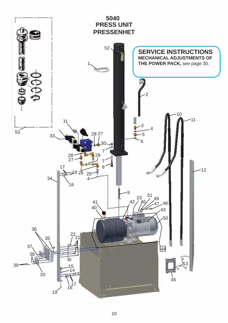
PRESS UNIT PRESSENHET
1
52
2
34
56
7
7
8
9
1415
16
16
19
20
17
17
18
2122
2526
2728
28 27
30
31
4041 42
4348
50
51
4723
44
32
33
34
35
36
37
38
39
29
418
1011
12
45
53
13
4649
5040
SERVICE INSTRUCTIONSMECHANICAL ADJUSTMENTS OF THE POWER PACK, see page 30.
11
PRESS UNIT PRESSENHET
ItemPart No. DescriptionNo. English Svenska 11 487 1140-00 Clamp Avgasklämma 2 487 1044-00 Hose Hydraulslang 3 486 3412-11 Pipe joint Koppling 4 486 1260-10 Rubber/steel washer Gummistålbricka 5 487 1135-00 Reducer Reducering 6 486 1260-30 Rubber/steel washer Gummistålbricka 7 486 1314-00 Lock washer Låsbricka 8 725 5542-50 Screw Skruv 9 725 6566-55 Screw Skruv 10 487 1041-00 Hose 59'' Hydraulslang 59'' 11 487 1042-00 Hose 65’’ Hydraulslang 65’’ 12 487 1100-00 Bracket Slangskena 13 487 1139-00 Clamp Avgasklämma 14 734 1823-51 Washer Bricka 15 725 2453-51 Screw Skruv 16 487 1024-00 Cam Nock 17 734 1146-01 Washer Bricka 18 725 5327-01 Screw Skruv 19 732 2118-01 Locking nut Låsmutter 20 487 1018-00 Bracket Fäste 21 725 5374-01 Screw Skruv 22 487 1016-00 Bracket Fäste för givare 23 486 9410-00 Capacitor Kondensator25 487 1121-00 Nipple Nippel 26 486 0122-00 Angle Koppling 27 486 6133-00 Coupling Adapter 28 486 1260-20 Washer Gummistålbricka 29 487 1080-00 Pipe Hydraulrör 30 731 2322-55 Nut Mutter 31 486 9736-00 Pressure sensor Tryckgivare 32 487 1129-00 Direction valve Riktningsventil 33 725 5339-01 Screw Skruv 34 487 1017-00 Guide Indikeringsstång 35 725 6371-01 Skruv Screw36 486 4531-00 Bearing Plastlager 37 732 2116-01 Locking nut Låsmutter 38 734 1153-01 Washer Bricka 39 724 1368-01 Screw Skruv 40 487 1120-00 Extension Påfyllningsadapter41 487 1137-00 Breather cap Andningsfi lter42 486 8930-00 Power pack Hydraulaggregat without motor utan motor43 486 9053-00 Motor Elmotor44 488 0598-00 Power pack compl. Hydraulaggregat komplett45 487 1427-00 Clamp plate Klammerplatta46 732 2118-01 Nut Mutter M847 734 1164-01 Washer Bricka BRB 8,448 725 2453-51 Screw Skruv49 487 1460-00 Capacitor holder Kondensatorfäste50 486 9053-01 Cover Fläktkåpa51 734 1164-31 Washer Bricka TBRB 8,4x16x352 487 1004-00 Hydraulic cylinder Presscylinder53 486 0460-00 Gaskets Packningssats
5040

12
1
1
2
2
3
44
8
9
10
11 12
5
67
7
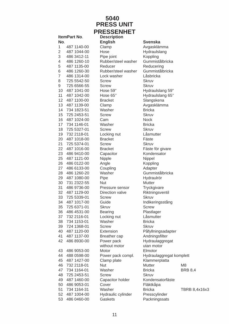
SWITCHGIVARE
5040
S10S10
S5S5
S7S7
S4S4
13
ItemPart No. DescriptionNo. English Svenska
11 486 7453-00 Inductive proximity Induktiv givare switch2 486 7504-00 Cable casing Kabelgenomförning3 486 9263-00 Switch Nyckelbrytare4 725 6368-01 Screw Skruv5 486 9265-00 Switch activator Nyckel
6 732 2116-01 Locking nut Låsmutter7 734 1153-01 Washer Bricka8 734 1146-01 Washer Bricka9 724 1331-01 Screw Skruv10 486 1094-00 Side location switch Gränslägesbrytare
11 734 1136-01 Washer Bricka12 724 1297-01 Screw Skruv
SWITCHGIVARE
5040
SERVICE INSTRUCTIONSMECHANICAL ADJUSTMENT OF ELECTRIC COMPONENTS
a) Model 5040 have a total of two proximity switches. The sensing range is set to max. 4 - 8 mm and a min. of 2 mm. b) Shutter switch.c) Side location switch.
S4
S7S5
a)a) b)b) c)c)

14
1 2 34
16
5
6
7
818
9
10
16
20 18
17 19
11
12
13
14
15
1
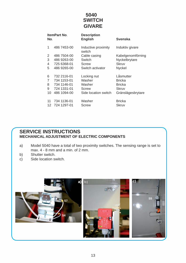
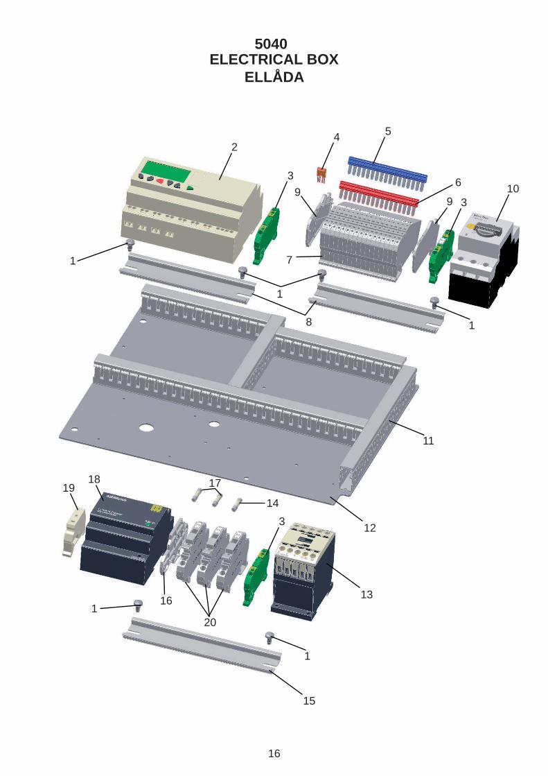
ELECTRICAL BOXELLÅDA
5040
15
ItemPart No. DescriptionNo. English Svenska
11 486 7302-00 Adaptor Adapter2 486 9384-00 LED element, green Lysdiodelement3 486 9444-00 Contact block Kontaktblock4 486 9446-00 LED element, white Lysdiodelement5 486 9399-01 Knob Dörrkopplingsved
6 486 3600-00 Cable casing Kabelförskruvning7 486 2021-00 Contact Stickkontakt 8 486 6810-00 Nut Mutter9 487 1123-00 Emergency stop lable Nödstoppsetikett10 486 9371-00 Electrical box Plåtlåda
11 487 1125-00 Decal Dekal12 486 9445-00 Contact block Kontaktblock 13 486 9443-00 Emergency stop Nödstopp14 486 9859-00 Decal Dekal 15 486 9376-00 Push button Lamptryckknapp
16 486 7300-00 Lamp Vit lampa17 486 9431-00 Nut Kontramutter18 486 7504-00 Cable casing Kabelförskruvning19 486 9430-00 Cable casing Kabelförskruvning20 486 9243-00 Nut Kontramutter
ELECTRICAL BOXELLÅDA
5040
SERVICE INSTRUCTIONSPROGRAMMING THE PLC-UNIT AND PARAMETERS IN THE PLC-UNIT, see page 32-
16
ELECTRICAL BOXELLÅDA
1
2
3
7
8
99
3
3
10
4 5
6
1
1
116
1918
20
11
12
13
15
14
17
1
5040

17
ELECTRICAL BOXELLÅDA
ItemPart No. DescriptionNo. English Svenska
11 729 5842-01 Screw Skruv2 486 9756-00 Logikenhet PLC unit3 486 9403-00 Ground conector Jordplint4 486 9402-01 Bridge Bygling 486 9402-00 Bridge Bygling5 486 9396-01 Bridge, red Byglingskam, röd 486 9396-00 Bridge, red
6 486 9397-00 Bridge, blue Byglingskam, blå 486 9397-01 Bridge, blue Byglingskam, blå7 486 9382-00 Connection block Givarplint 486 9382-01 Connection block Givarplint8 486 9419-00 Locking bar DIN-skena9 486 9398-00 Spacer Ändplatta 486 9398-01 Spacer Ändplatta10 486 5043-00 Motor circuitbreaker Motorskyddsbrytare
11 486 9428-00 Canduit Kabelkanal12 486 9372-00 Mounting plate Montageplåt13 486 9441-00 Contactor Kontaktor14 486 8242-00 Fuse Säkring15 486 9420-00 Locking bar DIN-skena
16 486 9406-00 Spacer Ändplatta17 486 3694-00 Glass fuse Säkring18 486 7344-00 Power unit LOGO-power19 486 9401-00 Spacer Ändstöd20 486 9405-00 Fuse terminal Säkringsplint
5040
SERVICE INSTRUCTIONSCHECKING THE PRESSUREa) Open the front shutter and remove the door. Attach the extension hose (4869834-00 to the pressure gauge 4862169-00)b) Push and hold the contactor (K1), maximum pressure should be set at 140 bars. (2030 PSI) Run the press plate down and check that the pressure shifts at 120 bars. (1740 PSI) NOTE; Quick movement of the needle.
18
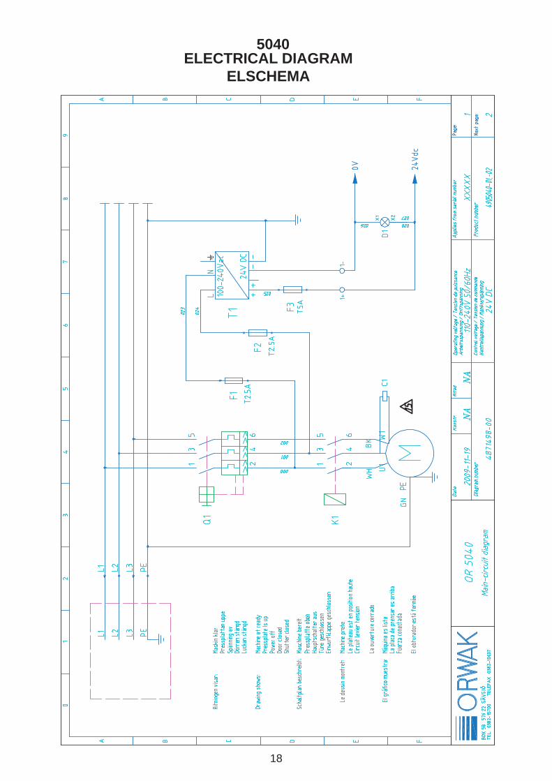
ELECTRICAL DIAGRAM ELSCHEMA
5040
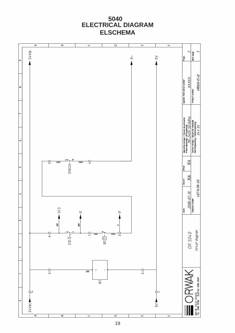
19
ELECTRICAL DIAGRAM ELSCHEMA
5040

20
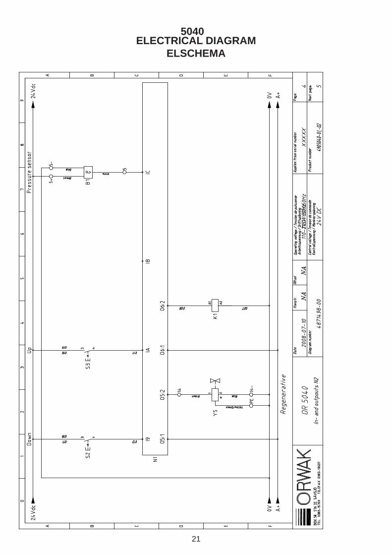
ELECTRICAL DIAGRAM ELSCHEMA
5040
21
ELECTRICAL DIAGRAM ELSCHEMA
5040
22
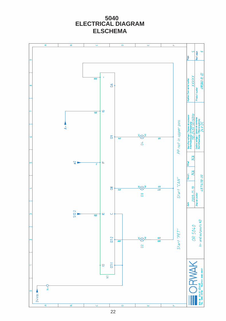
ELECTRICAL DIAGRAM ELSCHEMA
5040

23
ELECTRICAL DIAGRAM ELSCHEMA
5040
24
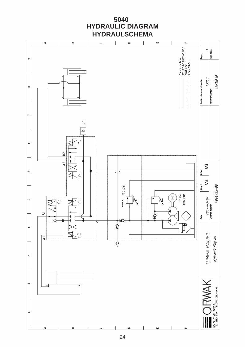
HYDRAULIC DIAGRAM HYDRAULSCHEMA
Y2
Y1
5040
25
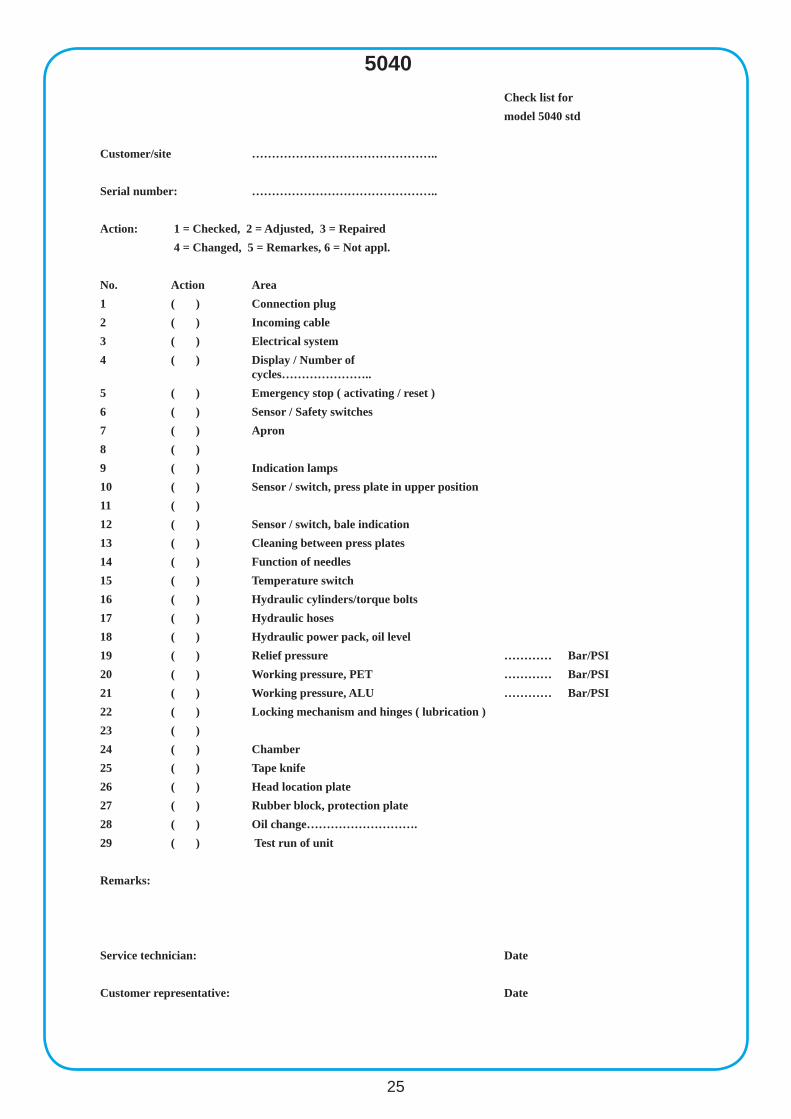
5040Check list for model 5040 std
Customer/site ………………………………………..
Serial number: ………………………………………..
Action: 1 = Checked, 2 = Adjusted, 3 = Repaired 4 = Changed, 5 = Remarkes, 6 = Not appl.
No. Action Area1 ( ) Connection plug2 ( ) Incoming cable3 ( ) Electrical system4 ( ) Display / Number of
cycles…………………..5 ( ) Emergency stop ( activating / reset )6 ( ) Sensor / Safety switches7 ( ) Apron 8 ( )9 ( ) Indication lamps10 ( ) Sensor / switch, press plate in upper position11 ( )12 ( ) Sensor / switch, bale indication 13 ( ) Cleaning between press plates14 ( ) Function of needles15 ( ) Temperature switch16 ( ) Hydraulic cylinders/torque bolts 17 ( ) Hydraulic hoses18 ( ) Hydraulic power pack, oil level19 ( ) Relief pressure ………… Bar/PSI20 ( ) Working pressure, PET ………… Bar/PSI21 ( ) Working pressure, ALU ………… Bar/PSI22 ( ) Locking mechanism and hinges ( lubrication )23 ( )24 ( ) Chamber25 ( ) Tape knife26 ( ) Head location plate27 ( ) Rubber block, protection plate28 ( ) Oil change……………………….29 ( ) Test run of unit
Remarks:
Service technician: Date
Customer representative: Date

26
5040
S1 Start button PET
S2 Down button
S3 Up button
S8 Start button CAND1 Power on
Q1 Motor protection device + Main switch
S12 Emergency stop
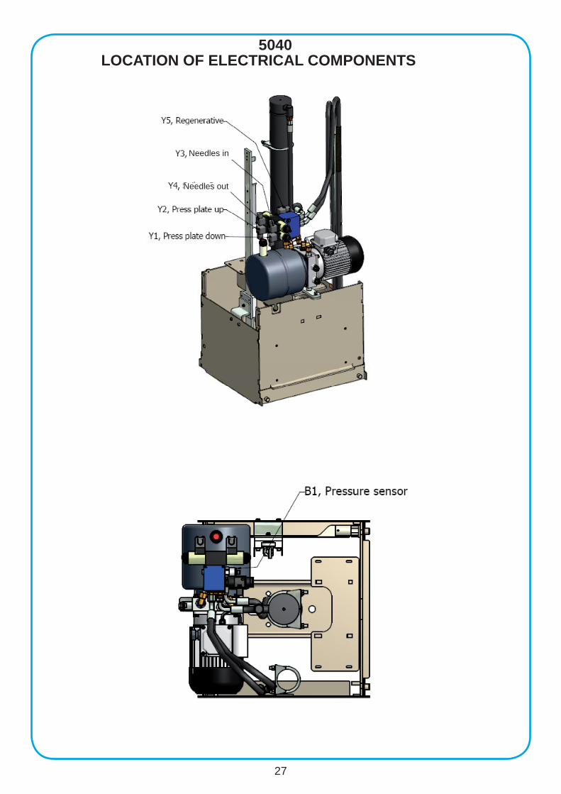
LOCATION OF ELECTRICAL COMPONENTS
S4 Upper limit switch
S7 Lower limit switch
S5 Side location switch
S10 Shutter switch
Switch activator
27
5040LOCATION OF ELECTRICAL COMPONENTS
Needles out
Needles in
28
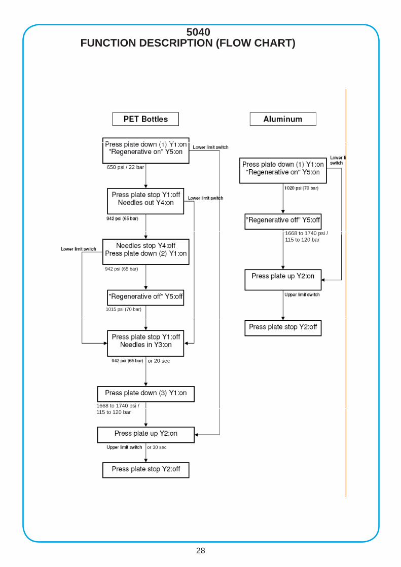
5040FUNCTION DESCRIPTION (FLOW CHART)
or 20 sec
650 psi / 22 bar
1668 to 1740 psi /115 to 120 bar
1668 to 1740 psi /115 to 120 bar
or 30 sec
942 psi (65 bar)
1015 psi (70 bar)
29
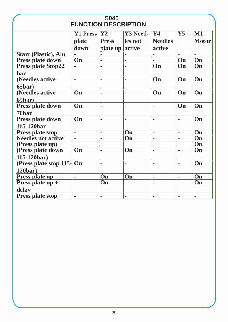
5040
Y1 Press plate down
Y2 Press plate up
Y3 Need-les not active
Y4 Needles active
Y5 M1 Motor
Start (Plastic), Alu - - - - - -Press plate down On - - - On OnPress plate Stop22 bar
- - - On On On
(Needles active 65bar)
- - - On On On
(Needles active 65bar)
On - - On On On
Press plate down 70bar
On - - - On On
Press plate down 115-120bar
On - - - - On
Press plate stop - - On - - OnNeedles not active - - On - - On(Press plate up) On(Press plate down 115-120bar)
On - On - - On
(Press plate stop 115-120bar)
On - - - - On
Press plate up - On On - - OnPress plate up + delay
- On - - On
Press plate stop - - - - - -
FUNCTION DESCRIPTION
30
5040
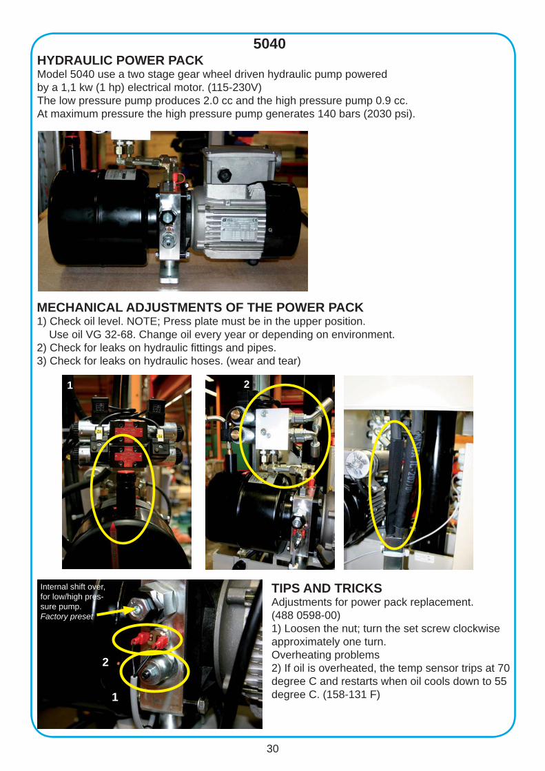
TIPS AND TRICKSAdjustments for power pack replacement. (488 0598-00)1) Loosen the nut; turn the set screw clockwise approximately one turn.Overheating problems2) If oil is overheated, the temp sensor trips at 70 degree C and restarts when oil cools down to 55 degree C. (158-131 F) 1
2
Internal shift over, for low/high pres-sure pump. Factory preset
HYDRAULIC POWER PACKModel 5040 use a two stage gear wheel driven hydraulic pump powered by a 1,1 kw (1 hp) electrical motor. (115-230V)The low pressure pump produces 2.0 cc and the high pressure pump 0.9 cc.At maximum pressure the high pressure pump generates 140 bars (2030 psi).
MECHANICAL ADJUSTMENTS OF THE POWER PACK1) Check oil level. NOTE; Press plate must be in the upper position. Use oil VG 32-68. Change oil every year or depending on environment.2) Check for leaks on hydraulic fi ttings and pipes. 3) Check for leaks on hydraulic hoses. (wear and tear)
1 2
31
5040

32
5040
(E-prom; 486 9986-00)
Remove the slot cover and put the memory card into the slot.Press ESC. Press the + (plus) button until “memory card” becomes highlighted in the display.Press OK. ”Stop program” Press OK. “Save” should now fl ash in the display, press OK.“Save program in memory card” should now displays, press OK.
“Saving program in progress” (Takes a minute) “Saving program complete”. Press OK. RUN fl ashing, press OK. RUN program, press OK.Remove the memory card and put back the cover.
PROGRAMMING FROM PLC-UNIT TO MEMORY CARD (Crouzet millenium 3)
33
5040
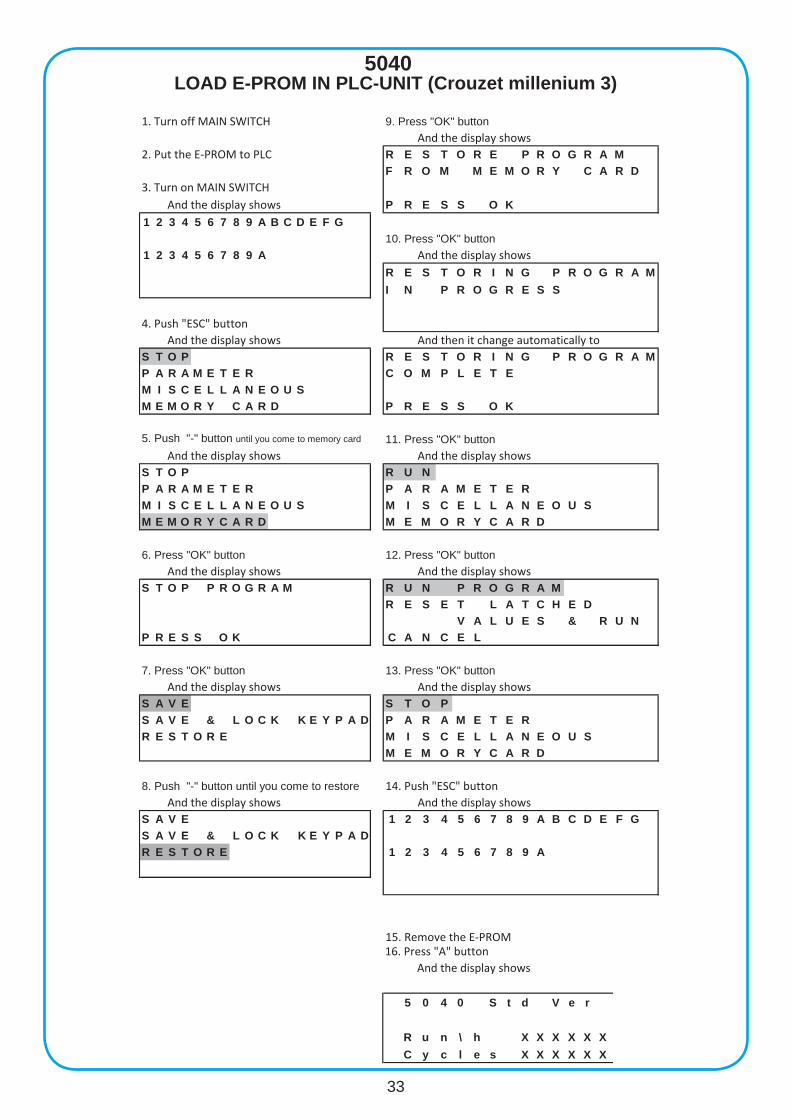
9. Press "OK" buttonAnd the display shows
R E S T O R E P R O G R A MF R O M M E M O R Y C A R D
P R E S S O K1 2 3 4 5 6 7 8 9 A B C D E F G
10. Press "OK" button1 2 3 4 5 6 7 8 9 A And the display shows
R E S T O R I N G P R O G R A MI N P R O G R E S S
And then it change automatically toS T O P R E S T O R I N G P R O G R A MP A R A M E T E R C O M P L E T EM I S C E L L A N E O U SM E M O R Y C A R D P R E S S O K
5. Push "-" button until you come to memory card 11. Press "OK" button And the display shows
S T O P R U NP A R A M E T E R P A R A M E T E RM I S C E L L A N E O U S M I S C E L L A N E O U SM E M O R Y C A R D M E M O R Y C A R D
12. Press "OK" button And the display shows
S T O P P R O G R A M R U N P R O G R A MR E S E T L A T C H E D
V A L U E S & R U NP R E S S O K C A N C E L
13. Press "OK" button And the display shows
S A V E S T O PS A V E & L O C K K E Y P A D P A R A M E T E RR E S T O R E M I S C E L L A N E O U S
M E M O R Y C A R D
14. Push "ESC" buttonAnd the display shows And the display shows
S A V E 1 2 3 4 5 6 7 8 9 A B C D E F GS A V E & L O C K K E Y P A DR E S T O R E 1 2 3 4 5 6 7 8 9 A
15. Remove the E-PROM
1. Turn off MAIN SWITCH
2. Put the E-PROM to PLC
3. Turn on MAIN SWITCHAnd the display shows
4. Push "ESC" buttonAnd the display shows
And the display shows
6. Press "OK" button And the display shows
7. Press "OK" button And the display shows
8. Push "-" button until you come to restore
16. Press "A" buttonAnd the display shows
5 0 4 0 S t d V e r
R u n \ h X X X X X XC y c l e s X X X X X X
LOAD E-PROM IN PLC-UNIT (Crouzet millenium 3)
34
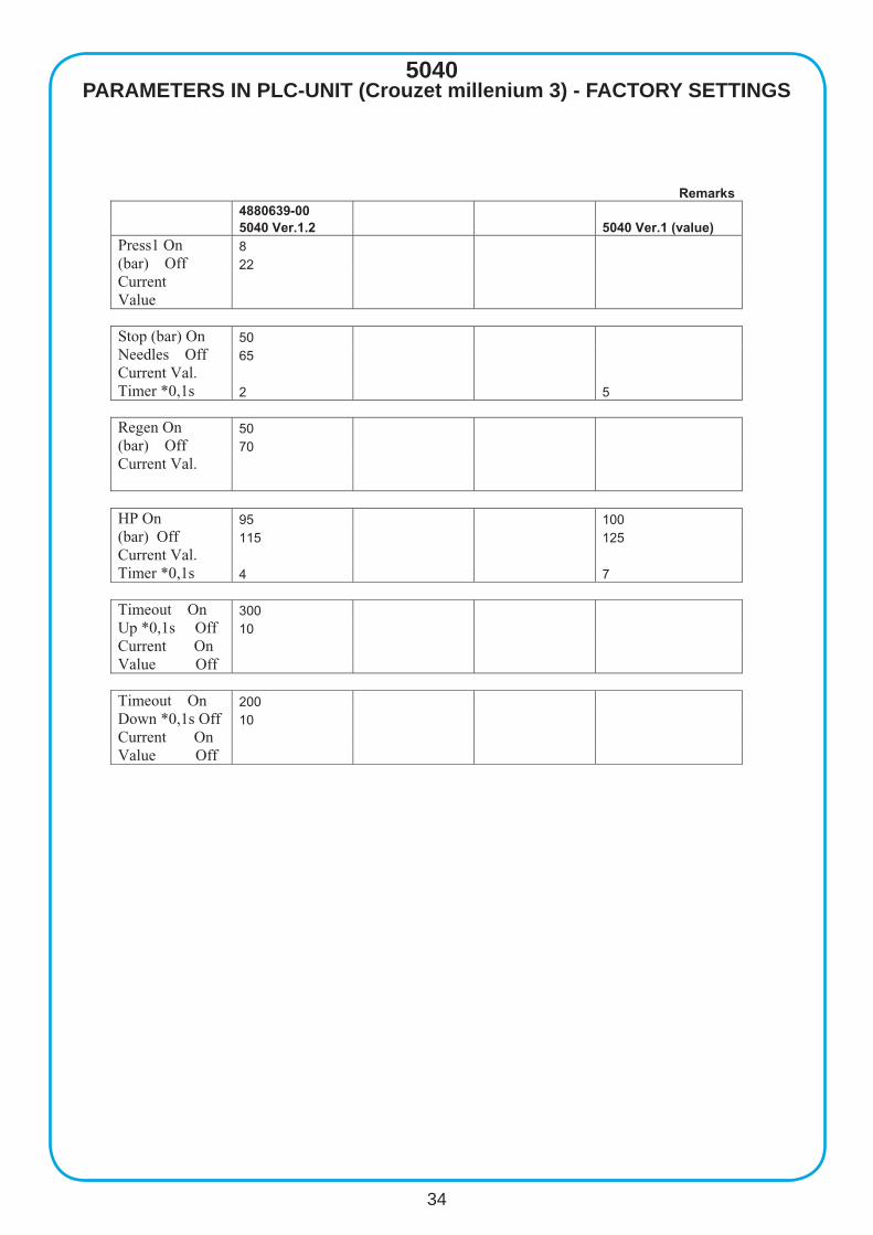
5040PARAMETERS IN PLC-UNIT (Crouzet millenium 3) - FACTORY SETTINGS
Remarks 4880639-00 5040 Ver.1.2 5040 Ver.1 (value) Press1 On 8 (bar) Off 22 Current Value Stop (bar) On 50 Needles Off 65 Current Val. Timer *0,1s 2 5 Regen On 50 (bar) Off 70 Current Val.
HP On 95 100 (bar) Off 115 125 Current Val. Timer *0,1s 4 7 Timeout On 300 Up *0,1s Off 10 Current On Value Off Timeout On 200 Down *0,1s Off 10 Current On Value Off
35
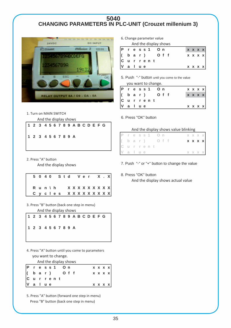
5040
1. Turn on MAIN SWITCH
And the display shows1 2 3 4 5 6 7 8 9 A B C D E F G
1 2 3 4 5 6 7 8 9 A
2. Press "A" button
And the display shows
5 0 4 0 S t d V e r X . X
R u n \ h X X X X X X X X XC y c l e s X X X X X X X X X
3. Press "B" button (back one step in menu)
And the display shows1 2 3 4 5 6 7 8 9 A B C D E F G
1 2 3 4 5 6 7 8 9 A
4. Press "A" button until you come to parameters
you want to change.And the display shows
P r e s s 1 O n x x x x( b a r ) O f f x x x xC u r r e n tV a l u e x x x x
5. Press "A" button (forward one step in menu)
Press "B" button (back one step in menu)
6. Change parameter value
And the display showsP r e s s 1 O n x x x x( b a r ) O f f x x x xC u r r e n tV a l u e x x x x
5. Push "-" button until you come to the value
you want to change.P r e s s 1 O n x x x x( b a r ) O f f x x x xC u r r e n tV a l u e x x x x
6. Press "OK" button
And the display shows value blinkingP r e s s 1 O n x x x x( b a r ) O f f x x x xC u r r e n tV a l u e x x x x
7. Push "-" or "+" button to change the value
8. Press "OK" button And the display shows actual value
CHANGING PARAMETERS IN PLC-UNIT (Crouzet millenium 3)
Orwak is a world leader in compaction and baling solu-
tions for solid waste material at source. We develop,
manufacture and market a comprehensive range of
waste compactors, baling systems and “Brickman” bri-
quette presses for recyclable materials that make waste
management more profi table. We also offer fully auto-
matic balers for recyclable materials through our sub-
sidiary Presona. This is where Orwak’s unequalled
technology, expertise and service support make all the
difference. When you partner with Orwak, you also gain
access to the vast experience we have built up over the
last 35 years.
Orwak is wholly owned by the Norwegian company
Tomra, a leading global player in providing integrated
solutions for recovering and recycling used packaging.
Leader in compaction
and baling solutions
AB OrwakBox 58, SE-576 22 Sävsjö, SwedenTel: +46 382-157 00, Fax: +46 382-106 07E-mail: [email protected]