edition 12.03 air conditioning - rafstjorn · air conditioning operating instructions. ... 21....
TRANSCRIPT

230/1/50-60 400/3/50
MINI-AIRA/C UNITS
Index 30AEdition 12.03
PRECISION A/C UNITS
AIR CONDITIONING
OPERATING INSTRUCTIONS

E/1203/30A/2
E/1203/30A/3
Contents PageIntroduction 4Technical Data 6Capacity Diagrams 8Dimensions 131. Unpacking and Inspection 142. Unit Identificaton 153. Operating Principle 164. Precautions 185. Safety Considerations 186. Precautions when handling the Unit 197. Installation 198. Vibrations 279. Mechanical Parts 2710. Cooling Components 2711. Motors 2812. Control, Monitoring and Safety Components 2913. Electrical Connections 3014. Start-up 3115. Adjusting the Temperature 3116. First Checks after starting the Unit 3217. Switching off 3218. Maintenance 3219. Inactivity 3320. Options 3421. Residual Hazards and Emergency Information 3622. Disassembling the Unit 4023. Faults, probable Causes, possible Remedies 41
The manufacturer reserves the right to make alterations without notice.

E/1203/30A/4
Introduction
The following information is supplied in accordance with Standards:CE73/23,CE93/68,CE89/392:
MANUFACTURER'S NAME AND ADDRESSSTULZ GmbHHolsteiner Chaussee 28322480 Hamburg
DATA REGARDING THIS MODELAir conditioner for telecom application
YEAR OF MANUFACTUREAs shown on the technical name plate on the unit
HOW TO CONSULT THIS MANUALThis document contains general informations valid for all models of the series. Furtherinformations like wiring diagrams etc. will be delivered with each unit.
THIS MANUAL IS INTENDED FOROWNER OF THE APPLIANCEPERSON RESPONSIBLE FOR ITS INSTALLATIONPERSON RESPONSIBLE FOR MANAGING THE PRODUCTPERSON RESPONSIBLE FOR ORDINARY MAINTENANCEPERSON RESPONSIBLE FOR ITS DISASSEMBLY
PURPOSE OF THE INFORMATION CONTAINED IN THIS MANUAL:CORRECT HANDLING performed by unskilled personnelCORRECT INSTALLATION performed by skilled personnel;CORRECT START-UP performed by personnel trained by STULZ;CORRECT MANAGEMENT performed by skilled personnel;CORRECT MAINTENANCE performed by skilled personnel;CORRECT ORDER FOR SPARE PARTS, made by skilled personnel;CORRECT DISPOSAL OF THE PRODUCT, made by skilled personnel.
RESTRICTIONS TO THE USE OF THIS MANUALThey apply to any operations that must be performed by highly skilled personnel.

E/1203/30A/5
WHERE AND HOW TO STORE THIS MANUALInside the electric cabinet or together with any other literature concerning the equipment whichutilizes the product, provided it is a dry and clean place.In the event of the manual being misplaced or damaged, the customer may require, for a fee, anew manual, by quoting the model and serial number shown on the technical name- plate, bycontacting your local STULZ partner.
CURRENT TECHNOLOGYThis manual reflects the state of the art existing at the time the product is marketed and shall notbe deemed to be inadequate for the sole reason that it has not been updated as a result of anynew experience.
UPDATESSTULZ reserves the right to update the product and relevant manual without being required toupdate previous products and manuals other than in exceptional circumstances. To require orreceive any updates of the instructions manual or amendments thereto, which shall be deemedto be an integral part of the manual, please contact your local STULZ partner.
FOR FURTHER INFORMATIONPlease contact your local STULZ partner.Any suggestions or recommendations made by installers or users of the product for the purposeof improving the product or the contents of this manual, will be greatly appreciated by theManufacturer.
IN THE EVENT OF SALE OF THE PRODUCTPlease advise STULZ GmbH of the address of the new owner so as to enable the dispatch ofany updates to the manual, otherwise STULZ GmbH shall be relieved of any subsequentliabilities

E/1203/30A/6
Technical Data CVC 07 001yy - CVC 20 001yy (at 50 Hz)
* 50°C at 60 Hz** measured at 2m distance from the unit rear side (condenser side), free field, external temp. higher than 40°C*** measured at 2m distance from the unit front side (evaporator side), free field, external temp. higher than 40°C
Cooling capacity L35L35 - (DIN3168)Cooling capacity L35L50 - (DIN3168)Refrigerant
Condenser fanNumber/TypeAir flow
Evaporator fanNumber/Type
Air flow
Refrigerant chargeExternal operating limit temp. min/maxCabinet operating limit temp. min/maxExternal noise level **Internal noise level ***Duty cycleWeightHeight / Width / Depth
Electrical Data
Power Supply CodeNominal voltageTolerance on voltagePhaseNominal frequencyTolerance on frequencyPower consumption L35L50Locked rotor current (LRA)Operating current (OA)
Condenser FanPower consumptionOperating current
Evaporator FanPower consumptionOperating current
20230
±10%1
50-60± 2%1190206.1
1650.73
610.27
CVC 20 0 01yy
20001700
R134a
1/Ø225 radial850
1/Ø190 radial
390
0.7-20/+55*+25/+45
716210044
1060/406/233
WW
m³/h
m³/h
kg°C°CdB(A)dB(A)%kgmm
V
phHz
WAA
WA
WA
CVC 07 0 01yy
750580
R134a
1/Ø190 radial400
1/Ø150 compact(axial)220
0.35-20/+55*+25/+45
625210025
774/308/221
CVC 14 0 01yy
14001170
R134a
1/Ø220 radial650
1/Ø190 radial
390
0.5-20/+55*+25/+45
736210042
1060/406/233
20230
±10%1
50-60± 2%400162.3
610.27
290.15
20230
±10%1
50-60± 2%850174.1
900.4
610.27
E/1203/30A/7
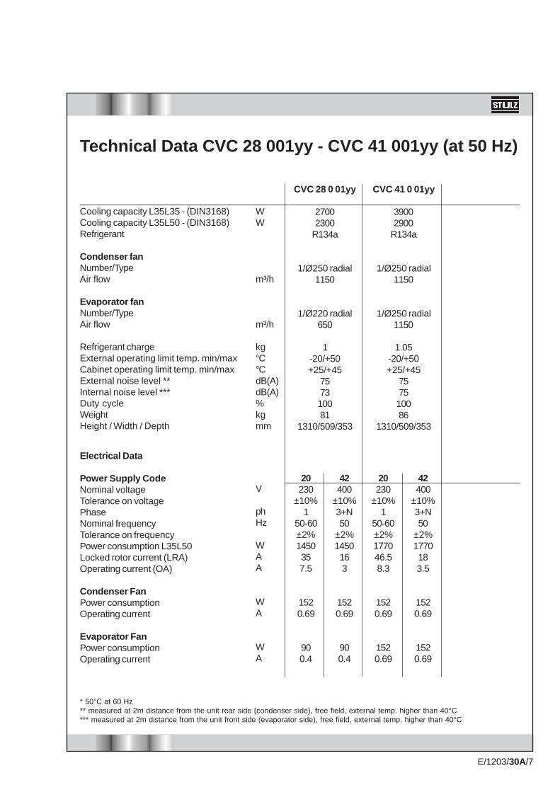
Technical Data CVC 28 001yy - CVC 41 001yy (at 50 Hz)
Cooling capacity L35L35 - (DIN3168)Cooling capacity L35L50 - (DIN3168)Refrigerant
Condenser fanNumber/TypeAir flow
Evaporator fanNumber/TypeAir flow
Refrigerant chargeExternal operating limit temp. min/maxCabinet operating limit temp. min/maxExternal noise level **Internal noise level ***Duty cycleWeightHeight / Width / Depth
Electrical Data
Power Supply CodeNominal voltageTolerance on voltagePhaseNominal frequencyTolerance on frequencyPower consumption L35L50Locked rotor current (LRA)Operating current (OA)
Condenser FanPower consumptionOperating current
Evaporator FanPower consumptionOperating current
* 50°C at 60 Hz** measured at 2m distance from the unit rear side (condenser side), free field, external temp. higher than 40°C*** measured at 2m distance from the unit front side (evaporator side), free field, external temp. higher than 40°C
WW
m³/h
m³/h
kg°C°CdB(A)dB(A)%kgmm
V
phHz
WAA
WA
WA
CVC 28 0 01yy
27002300
R134a
1/Ø250 radial1150
1/Ø220 radial650
1-20/+50+25/+45
757310081
1310/509/353
CVC 41 0 01yy
39002900
R134a
1/Ø250 radial1150
1/Ø250 radial1150
1.05-20/+50+25/+45
757510086
1310/509/353
42400
±10%3+N50
±2%1450163
1520.69
900.4
42400
±10%3+N50
±2%1770183.5
1520.69
1520.69
20230
±10%1
50-60±2%1450357.5
1520.69
900.4
20230
±10%1
50-60±2%177046.58.3
1520.69
1520.69
E/1203/30A/8
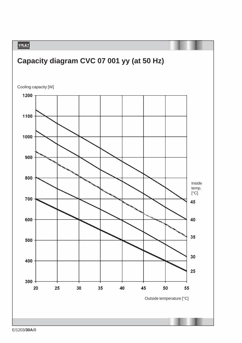
Capacity diagram CVC 07 001 yy (at 50 Hz)
Cooling capacity [W]
Outside temperature [°C]
Insidetemp.[°C]

E/1203/30A/9
Capacity diagram CVC 14 001 yy (at 50 Hz)
Cooling capacity [W]
Outside temperature [°C]
Insidetemperature[°C]
E/1203/30A/10
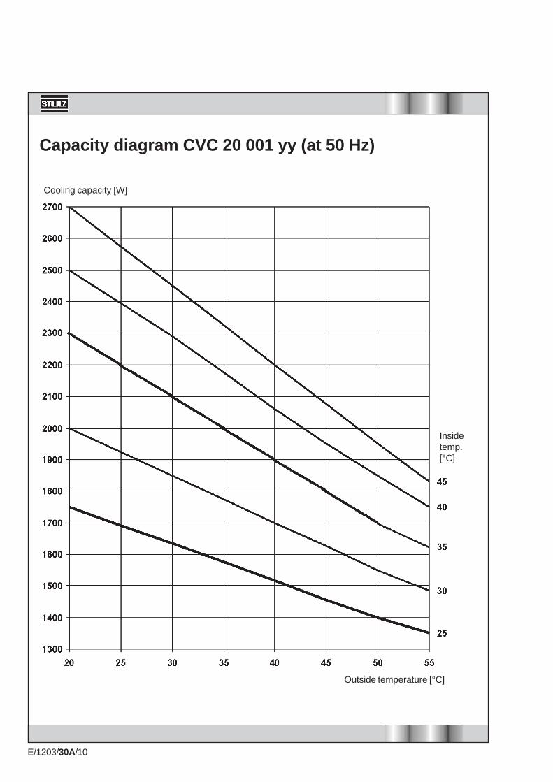
Capacity diagram CVC 20 001 yy (at 50 Hz)
Cooling capacity [W]
Outside temperature [°C]
Insidetemp.[°C]

E/1203/30A/11
Capacity diagram CVC 28 001 yy (at 50 Hz)
Cooling capacity [W]
Outside temperature [°C]
Insidetemperature[°C]

E/1203/30A/12
Capacity diagram CVC 41 001 yy (at 50 Hz)
Cooling capacity [W]
Outside temperature [°C]
Insidetemp.[°C]

E/1203/30A/13
B
A
C
Dimensions
TypeCVC 07CVC 14-20CVC 28-41
A774
10601310
B308406509
C221233353
E/1203/30A/14
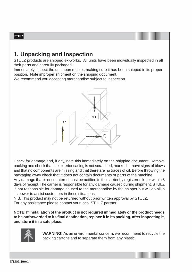
1. Unpacking and InspectionSTULZ products are shipped ex-works. All units have been individually inspected in alltheir parts and carefully packaged.Immediately inspect the unit upon receipt, making sure it has been shipped in its properposition. Note improper shipment on the shipping document.We recommend you accepting merchandise subject to inspection.
Check for damage and, if any, note this immediately on the shipping document. Removepacking and check that the exterior casing is not scratched, marked or have signs of blowsand that no components are missing and that there are no traces of oil. Before throwing thepackaging away check that it does not contain documents or parts of the machine.Any damage that is encountered must be notified to the carrier by registered letter within 8days of receipt. The carrier is responsible for any damage caused during shipment. STULZis not responsible for damage caused to the merchandise by the shipper but will do all inits power to assist customers in these situations.N.B. This product may not be returned without prior written approval by STULZ.For any assistance please contact your local STULZ partner.
NOTE: If installation of the product is not required immediately or the product needsto be onforwarded to its final destination, replace it in its packing, after inspecting it,and store it in a safe place.
UP
UP
UP
WARNING! As an environmental concern, we recommend to recycle thepacking cartons and to separate them from any plastic.

E/1203/30A/15
This unit can be correctly identified by thetechnical name-plate containing all theinformation for its correct use.In addition to the manufacturer's identificationdata and the product trade-marks, the name-plate contains the following information:
The technical name-plate is embossed on aplastic support which ensures high enduranceof the text even in par ticularly difficultenvironments.
N.B. For any assistance or informationconcerning the unit described in this manual,knowledge of its serial number is essential.
2. Unit IdentificationConstructor TrademarkModelSeriesDate
Nominal voltageControl voltage
PhaseFrequency
Start/Run current
Cooling capacity
Power absorbed
Automatic circuit breaker curve type C, Safetyfuse type aM
Inside temperature
Outside temperature
Refrigerant charge
Type of refrigerant
Maximum pressure
Cabinet side protection IP
Ambient side protection IP
WeightDuty Cycle
This identifies the product family.Product identification number.Date on which the product is placedon the market and date ofcommencement of warranty.Voltage to be supplied to the unitWorking voltage of the auxiliarycircuits if different from the voltagerating.Voltage phaseVoltage frequency.
Current absorbed when starting the compressor. /Current absorbed during operation at the permittedmaximum temperature
Unit cooling capacity with 35°C inside cabinettemperature and 35°C ambient temperature conditions.
Power absorbed by the unit with 35°C inside cabinettemperature and 50°C ambient temperature conditions.
Rating of the automatic switch/safety fuse to be installedby the installer.
Minimum and maximum cabinet temperature where themachine works and for which the machine wasdesigned.
Minimum and maximum ambient temperature wherethe machine works and for which the machine wasdesigned
Quantity of refrigerant contained in the unit'srefrigeration circuit
Brand name of the refrigerant used in the unit's coolingcircuit
Maximum pressure at which the refrigeration circuitfunctions
protection level in the direction of the cabinet
protection level in the direction of the ambientEmpty weight of the machineOperational capacity of the unit

E/1203/30A/16
���������Condenser
Condenser fan
Evaporator fan
Regulatingthermostat
Evaporator
HP switch
Compressor
Capillary pipe
3. Operating PrincipleSTULZ conditioners are designed to cool electric cabinets with IP54 protection level andthey are suitable for the operation in industrial environments. Their use allows to eliminateproblems caused by high temperatures, dirt and humidity which are present in theenvironment.The unit, which is basically made up of a sealed cooling circuit where the refrigerantcirculates, is divided into two sections, hermetically separated from each other, where theair in the environment and the air in the cabinet are treated without coming into contactwith each other.
The system operates as follows:The compressor compresses the refrigerant gas bringing it to a high pressure andtemperature.The hot gas, by going through the condenser, is cooled and liquefied thus releasing heatto the air in the environment. Pushed through the capillary pipe, the liquid refrigerant losespressure, which makes it prone to evaporation. This takes place in the evaporator, wherethe refrigerant absorbs the heat of the warm air from the cabinet, which is therefore cooled.
LP switch
Filter dryerCondenser pressureswitch (proportional control)

E/1203/30A/17
Air flow inside the unit
Evaporator
Compressor
Evaporator fan
Condenser fan
Condenser
EXTERNAL SIDEINTERNAL SIDE
NOTE: The evaporator air flow of Mini-Air CVC07 is different from the illustrated air flow. Theevaporator air intake is from the top of the unit instead of as for the other units from thefront. Therefore, during installation, the necessary space for a proper room air intake atthe unit's top has to be left free.
E/1203/30A/18
4. PrecautionsThe CVC series cooling units are designed to operate as a wall-type unit and in an uprightposition. For all models the compressor is and must always be in an upright position.Thecooling units may not be used or transported in a position other than that for which theyhave been designed.
WARNING!Never run the machine if you have discovered leakage of the coolant fluid.
If traces of oil are present on the unit, which point to a loss of coolant, on the inside or theoutside, then the equipment must be thoroughly checked before starting the unit and, ifnecessary, the technical department of your local STULZ partner should be contacted.
5. Safety ConsiderationsThe installation and handling of cooling units may be hazardous as they form a pressurisedsystem with electric components.Only skilled personnel may repair, inspect or maintain the cooling units.All other operations must be performed by personnel who are experienced and qualified inthe maintenance of cooling systems.Before servicing this unit, refer to the instructions contained in this manual, check the dataon the data plate and follow any other precaution to ensure optimum safety.
WARNING!Never work on the unit without having disconnected the power supplybefore !

E/1203/30A/19
7. Installation1 Unpack the unit taking care not to damage its exposed parts. Before discarding it,
check the packaging for any parts or documents. Check that the supply voltage is asdesignated.
2 Check that:- there is space enough for an easy application and installation, both inside andoutside the cabinet;- the cabinet is at least of the IP54 type;- the cabinet is clean on the inside;- the cabinet is not in the proximity of heat sources or warm air flows;- the inside of the cabinet allows a proper air circulation, preventing any recirculation.It is important to prevent hot air expelled by the condenser fan from being even partiallysucked back in. This would cause continuous stoppages, commanded by the pressureswitches, reducing efficiency and increasing electricity consumption. Improper operationof this type can quickly cause irreparable harm to the compressor.- units have to be fixed at the cabinet wall or at the cabinet door, which can support theirweight
6. Precautions when handling the Unit
To move this unit, when it is still packaged, usea fork lift or a system using cables or chains.When the packing is removed, use two M6eyebolts, attaching them to the upper part of thecooling unit, where appropriate holes havealready been arranged.

E/1203/30A/20
Failure to comply with these requirements, in addition to affecting proper unitoperation, invalidates warranty coverage.
adhesive gasket
WARNING!Do not obstruct circulation by air being sucked into or expelled from the airconditioner.
3 The cooling unit must be installed as high as possible;4 If installed on a door, make sure the hinges can withstand the weight of the unit;5 make sure the electric cable is not torn or damaged when the door is closed;6 If the depth of the cooling unit prevents the door from being completely opened, arrange
a stopper for such a door.7 Prior to servicing the cabinet, disconnect power supply to the same.
Prior to drilling holes or making cuts on the cabinet, make sure that holes, screws,cables, etc. do not interfere with the equipment which has already been installed. Makecuts on the cabinet panels by following the relevant template.
8 Once the anchoring holes have been drilled in the cabinet wall, mount the eyebolts tohandle the unit. the necessary cut-outscorresponding to the unit size can be seen onthe following pages.
9 Glue the adhesive gasket around the edges ofthe holes drilled on the cabinet;
10 Position the cooling unit at the cabinet andsecure it with the appropriate screws.
NOTE:Mini-Air units are already provided with threadedinserts, in correspondance with the fixing holes at thecut-out.Therefore the fixing holes at the cabinet wall must notbe provided with threaded inserts.
NOTE:Mini-Air units are provided with a 3m power supplycable. Therefore leave a minimum distance of 200 mmfrom the top of the unit to the shelter ceiling duringinstallation.
threaded inserts
threaded inserts

E/1203/30A/21
Cut-out for CVC 07 001yy (Type 1)common cut-out for inlet and outlet
Provide a baffle toseparate the condenserinlet/outlet airflows !
30827
263
260
4 x Ø8
720
520
774
27
35.5

E/1203/30A/22
Cut-outs for CVC 07 001yy (Type 2)separate cut-outs for inlet and outlet
308
27
263
260
4 x Ø8
720
131
774
27
35.5
263
132.
525
6

E/1203/30A/23
Cut-out for CVC 14 001yy - CVC 20 001yy (Type 1)common cut-out for inlet and outlet
Provide a baffle toseparate the condenserinlet/outlet airflows !
343
50
20 366
6 x Ø8
1060
450
420
30
82
20
406
31.5 31.5
980

E/1203/30A/24
Cut-outs for CVC 14 001yy - CVC 20 001yy (Type 2)separate cut-outs for inlet and outlet
343
50
20 366
6 x Ø8
1060
450
420
30
82
20
406
31.5 31.5
461
219
300

E/1203/30A/25
Cut-out for CVC 28 001yy - CVC 41 001yy (Type 1)common cut-out for inlet and outlet
Provide a baffle toseparate the condenserinlet/outlet airflows !
407
50
39.5430
6 x Ø8
1235
480
520
25
250
39.5
509
515113
10
60

E/1203/30A/26
Cut-outs for CVC 28 001yy - CVC 41 001yy (Type 2)separate cut-outs for inlet and outlet
209
509
449 3030
6 x Ø8
39,5
250
480
520
27
1310
60
165
107294107
619
39,5 430

E/1203/30A/27
8. VibrationsThe cooling unit does not produce any significant vibrations as the parts which generate them areinstalled on anti-vibration devices.
9. Mechanical Parts
9.1 STRUCTUREThese machines are composed using self-supporting panels. These are made of passivated andbaked enamel sheet metal to guarantee resistance against corrosion*. They make the machineeasy to inspect and, at the same time, offer adequate protection to its internal components.Internal components of the structure are only accessible by removing cladding panels. These areremoved by extracting their fastening screws using suitable tools.* suitable only for non-corrosive and non-salty environments
10. Cooling ComponentsThese are connected together by copper piping, appropriately welded to ensure a good seal.
10.1 REFRIGERANTThe refrigerant that is used: R134a (Tetrafluorethane).It is neither toxic nor flammable and is not harmful to the ozone layer (ODP = 0).
10.2 COMPRESSORIn this unit a reciprocating hermetic compressor is used.Compressors are basically composed of an electric motor and a mechanical section which ispowered by this motor for pumping the refrigerant gas.In reciprocating compressors the pumping unit consists of a piston which slides inside a cylinderand which generates, depending on its phase, compression and aspiration.
10.3 CONDENSERThis part allows the release of the heat of the refrigerant gas in the environment. It consists of anexchange pack with copper piping and aluminium fins.(suitable only for non-corrosive and non-salty environments)
10.4 FILTER DRYERThis is a mixed mechanical/chemical filter and serves the purpose of filtering the refrigerant whichgoes through it, at the same time eliminating humidity particles.
10.5 CAPILLARY PIPE EXPANSION SYSTEMThis part causes a pressure drop of the refrigerant, before it comes into the evaporator.

E/1203/30A/28
10.6 EVAPORATORThis is the part where the transfer of the heat, contained in the air in the cabinet, to the refrigerantgas takes place .It consists of copper pipes and aluminium fins.(suitable only for non-corrosive and non-salty environments)
11. Motors
11.1 COMPRESSORElectric motor with a squirrel cage rotor, positioned inside the compressor and cooled by the airflow. It is mounted on anti-vibration springs to reduce vibrations.
11.2 FANSThese may be of different types depending on the model. They are either:- multiblade axial, with outside rotor on bearings, dynamically balanced;- compact axial, on bearings;- radial, with plastic or metal rotor, on bearings;These fans are manufactured in accordance with Standard EN 60 335 1. They are treated withanticorrosion plastic materials, with class B insulation and class 1 protection.The motor protection is IP44, in accordance with Standard DIN40500 whereas the safety ratecomplies with Standards DIN30110.Noise levels are consistent with Standard DIN 45635.

E/1203/30A/29
12. Control, Monitoring and Safety ComponentsAll equipment is set and inspected at the factory and generally does not require further adjustmentsor interventions.If, for specific reasons, it becomes necessary to perform modifications on the settings of automaticdevices this task must only be performed, subsequent to notification to the STULZ engineeringservice, by specialized product expert.STULZ air conditioner are equipped with a set of devices designed to ensure proper operation.Intervention by any one of these automatic safety devices is a sign of a malfunction and it isabsolutely necessary to eliminate the cause of the malfunction.
WARNING!It is prohibited to make electrical by-passes on safety equipment.This intervention, in addition to being dangerous, also immediately invalidates guaranteecoverage for the product.
Interrupt electrical power to the unit before performing any repair or maintenance.
Work on the unit must only be done by expert, qualified and authorized personnel.
12.1 HIGH PRESSURE SAFETY SWITCHstops compressor operation when the pressure inside the refrigeration circuit exceeds the designvalues.
12.2 LOW PRESSURE SAFETY SWITCHstops compressor operation when the pressure inside the refrigeration circuit drops below thedesign values.
12.3 CONDENSATION CONTROL PRESSURE SWITCH (fan speed control )It controls the condenser fan speed to keep the condensing temperature constant.Changes of fan speed are obtained by changing the supply voltage depending on the condensertemperature.
12.4 CONTACTORScontrol the motors by operating with auxiliary voltage.They refer to IEC947-4-1 standards.
12.5 TRANSFORMERrefers to EN60742 standard and transforms the supply voltage to the auxiliary control voltage.
12.6 REGULATING THERMOSTATThe mechanical thermostat with a gas charge is positioned at the evaporator air intake and itmeasures and controls the temperature to provide the start signal for the compressor. It can beadjusted within the allowed temperature range of the technical data sheet.
12.7 HEATING ELEMENT THERMOSTAT (supplied with the reheat option, only for CVC14/20/28/41)The mechanical thermostat with a gas charge is positioned at the evaporator air intake and itmeasures and controls the temperature to provide the start signal for the heating element.

E/1203/30A/30
13. Electrical Connections
WARNING!It is absolutely necessary, before making any connections, to use a suitable tester tocheck the supply voltage. This must be the same as the voltage indicated on the technicaldata plate.
The user must furnish and install, upstream from the unit, an isolating switch with a pre-fuse and capacity as specified on the technical plate in order to be able to performmaintenance on the unit in the absence of electricity.
• Check the supply voltage and frequency;• Check that supply voltage and frequency are compatible with those for the unit.• Interrupt both main power and auxiliary power before working on the system;• Select connection cables (not supplied) according to EN60204-1 Standards• On the main power supply lines, in preference install an omni-pole automatic switch, curve type
C, eventually complete of another differential switch. Alternatively, besides the isolating omni-pole switch, install a safety fuse, retarded, aM type;
• Check that power cables are installed with a sufficient distance from alarm cables.• Check that the supply voltage of the cooling unit is disconnected when opening the cabinet
doors.• To connect power supply, use cables with section suitable to the power absorbed by the users.
These cables must be compliant with current standards.
ATTENTION!The inobservance of these instructions might provoke damages or malfunction of components andthe warranty shall become forthwith void.
E/1203/30A/31
14. Start-up
Supply voltage to the cooling unit.If the temperature in the room is lower than the temperature set on the thermostat the evaporatorfan will start and will cause air recirculation in the cabinet.If the temperature in the room is higher than the temperature set on the thermostat then thecompressor and the condenser fan will start. They will operate until the temperature in the roomfalls below the value set on the thermostat.
Note!Avoid sudden stops and re-starts. At least 3 minutes should elapse between a stop and the nextre-start.
15. Adjusting the Temperature
Note!Excessively low cabinet temperatures may cause serious problems to the cabinet parts and requirean increased power consumption for a higher cooling capacity.
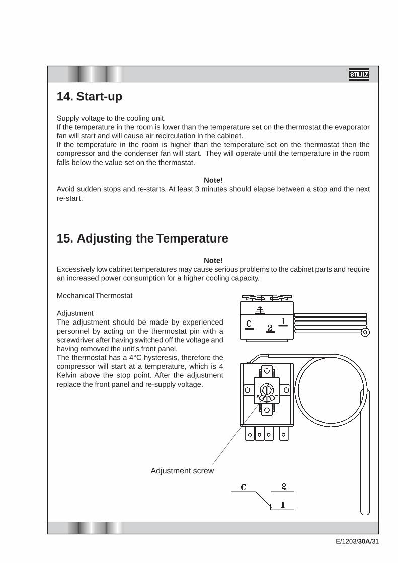
Mechanical Thermostat
AdjustmentThe adjustment should be made by experiencedpersonnel by acting on the thermostat pin with ascrewdriver after having switched off the voltage andhaving removed the unit's front panel.The thermostat has a 4°C hysteresis, therefore thecompressor will start at a temperature, which is 4Kelvin above the stop point. After the adjustmentreplace the front panel and re-supply voltage.
Adjustment screw

E/1203/30A/32
16. First Checks after Starting the UnitCheck that the air being released from the condenser into the environment flows correctly withoutbeing drawn into the cooling unit.Check that the evaporator fan functions properly.Check, with the unit running, that the supply voltage remains within the values indicated on thetechnical data plate
17. Switching off the UnitTo switch off the unit, disconnect the supply voltage from the system .
18. MaintenanceVery little ordinary maintenance is necessary, in view of the reliability and total automation of movingparts. This maintenance, however, must be performed according to prescribed maintenance intervals.Failure to perform maintenance, in addition to affecting the unit durability and operation, invalidatesthe warranty.
WARNING!Switch off the power supply of the unit before performing any maintenance measures.
18.1 PREVENTIVE MAINTENANCE SCHEDULETwo monthlyCheck that the unit's condensate drainage system is perfectly clear and operational.YearlyCheck that the fans do not show signs of overheating or abnormal vibrations.Check that the exchangers are efficient and not soiled.
Note: If the air conditioner works in exceptionally dirty environments or if experience shows that itrequires more frequent maintenance then this maintenance must be performed as required.
Note: After each scheduled and unscheduled service:check that the condensate drainage system is perfectly efficient.
18.2 EXTRAORDINARY MAINTENANCE INTERVALSEvery 3 years or every 10,000 operating hours the unit must undergo a general overhaul either atthe manufacturer's factory or at companies authorized by STULZ or by qualified agencies at thecustomer's own expense.

E/1203/30A/33
19. InactivityIf the unit remains inactive for longer periods of time, it is necessary to drain any condensateresidue and carry out a general cleaning procedure.
18.3 REPLACEMENT OF PARTSTo guarantee continuity of service to the units, it is recommended to replace some componentsaccording to their MTBF (medium time before failure).You can find the MTBF of the most critical components in the following table:
COMPRESSOR: 30,000 operating hoursCONDENSER FAN: 35,000 operating hoursEVAPORATOR FAN: 40,000 operating hoursMECHANICAL THERMOSTAT: 100,000 cyclesCOMPRESSOR RELAY: 200,000 cycles
NOTE: the MTBFs in the table above are referred to the time during which the components areoperating. The ratio between this time and the total time of service depends on the type of application,except for the evaporator fan (operating time is 100% of total service time).
Example:If you esteem that the compressor will be operating 60% of the total time, the MTBF will be 30,000working hours / 0.6 = 50,000 hours.
18.4 HOW TO CLEAN THE UNITDo not use acid or caustic substances to clean any part of the air conditioner.
The inner parts of the cooling unit, either on the room or cabinet side, must be cleaned with a liquiddetergent and compressed air having a pressure not higher than 4 bar, with the unit properly earthed.
To clean the condenser remove the external lower grill and rinse with compressed air opposite tothe normal air flow direction through the heat exchanger.
E/1203/30A/34
20. Options
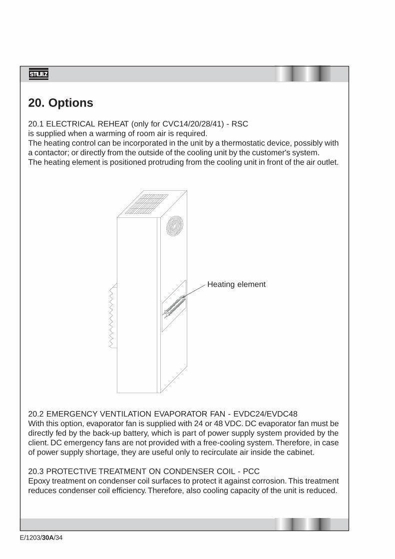
20.1 ELECTRICAL REHEAT (only for CVC14/20/28/41) - RSCis supplied when a warming of room air is required.The heating control can be incorporated in the unit by a thermostatic device, possibly witha contactor; or directly from the outside of the cooling unit by the customer's system.The heating element is positioned protruding from the cooling unit in front of the air outlet.
20.2 EMERGENCY VENTILATION EVAPORATOR FAN - EVDC24/EVDC48With this option, evaporator fan is supplied with 24 or 48 VDC. DC evaporator fan must bedirectly fed by the back-up battery, which is part of power supply system provided by theclient. DC emergency fans are not provided with a free-cooling system. Therefore, in caseof power supply shortage, they are useful only to recirculate air inside the cabinet.
20.3 PROTECTIVE TREATMENT ON CONDENSER COIL - PCCEpoxy treatment on condenser coil surfaces to protect it against corrosion. This treatmentreduces condenser coil efficiency. Therefore, also cooling capacity of the unit is reduced.
Heating element

E/1203/30A/35
1 2
FL3
M1/
14
M1/
15
20.4 ALUMINIUM CASING - CVCALWith this option, casing of the unit is made of aluminium instead of standard steel zincplated sheet. As standard, aluminium casing is not painted.
20.5 HIGH/LOW TEMPERATURE ALARM THERMOSTAT - TMC/TMFTMC (option for high temperature signal) and TMF (option for low temperature signal) aremechanical wall-mounted thermostats. They consist of thermostats with bi-metallic sensorelement for switching signal transmitters. Their adjustable range is from 0°C to 60°C, contacts6A-250VAC. Type of contacts NC for TMC and NO for TMF.
20.6 RELAY FOR POTENTIAL FREE COMMON ALARM SIGNAL (HIGH AND LOWPRESSURE, HIGH TEMPERATURE) - CAHP (high pressure alarm), LP (low pressure alarm) are not available as separate signals.CA, common alarm, is the consequence of the following alarms (high pressure+lowpressure+high temperature). When one of these three symptoms appears, common alarmis activated to warn about possible faults on the unit.
20.7 AIRFLOW SIGNAL - FLIt consists of a differential air pressure switch. It provides a voltage-free signal by a N.O.contact when air flow pressure is different from the rated value, to indicate a fan malfunction.This value of intervention is factory pre-set according to the unit model.
E/1203/30A/36
21. Residual Hazards and Emergency Information
This unit was designed to reduce danger sources or situations to a minimum.These dangers arise from improper use of the product or from failure to comply with installation andoperating instructions.All personnel who work on or near the unit must be familiar with these instructions.
21.1 GENERAL SAFETY PROVISIONSAll personnel charged with testing and maintaining the unit must be familiar with the following safetyregulations:· Danger signs must be easily visible in areas of potential danger.· A visual supervision service must be set up in danger areas.· Supervisors must keep constant contact with controllers.· Transit zones, doors and ladders placed near the area where the unit is located must never be
blocked.· Emergency exits must never be blocked.· Slippery areas that could be a potential risk for persons must be covered with anti-slip materials.· Proper tools and suitable procedures must be used for every specific activity.· Test tools and equipment must be kept in good order.· Personnel must have in-depth knowledge of methods and procedures to apply in case of fire (set
up a fire extinguisher service in a handy position).· The following actions must be taken if a fire starts:- Switch off the electrical power supply to the component that is burning.- Switch off all fans so as to cut the oxygene supply.- Advise the appropriate department.
21.2 HAZARDS ARISING FROM THE PRODUCT COMING INTO CONTACT WITHTHINGS OR PERSONS· Danger point 1a) comes from movement by the fan. The grating mesh has a useful gap, between
wires, smaller than 10 mm. Particles with smaller dimensions could be ejected by the fan blade.· Danger point 1b) comes from accidental contact with the heat exchanger since its aluminium fins
can have sharp edges.
21.3 HAZARDS ARISING FROM ELECTRICAL FAULTS
21.3.1 SAFETY STANDARDS FOR ELECTRICAL EQUIPMENTIntroductionThe causes of electrical risks are well known and it is not difficult to prevent these risks by applyingconstant care and attention.Assigned personnel must be informed regarding potential dangers and trained regarding safetyprocedures in order to reduce the number of potential electrical accidents.
E/1203/30A/37
21.3.2 TASKS ASSIGNED TO PLANT MANAGERSPlant managers must be informed regarding potential risks in the system and must superintendpersonnel that works with electrical equipment.Superintending tasks consist of localizing possible risk situations and investigating problemsencountered by personnel when performing maintenance.Each defective component must be immediately repaired or replaced.The manager must insist on application of safety measures. He must not tolerate or accept deviationsfrom these because this could cause harm to persons or to the machinery.
21.3.3 HIGH VOLTAGEContact with high voltage circuits can cause burns, shock, unconsciousness or even death for thepersons involved.This problem can be caused by poor understanding of the dangers inherent to use of electricaldevices.Damage to the human body, in this case, depends on the intensity of current, the duration ofcurrent and the path the current takes as it goes through the body.
21.3.4 SAFETY STANDARDS TO COMPLY WITH WHEN THE EQUIPMENT ISSWITCHED OFFInterrupt the power supply to the unit before opening it.Make sure no electricity is present in the unit's circuits.Clean and dry the work area.Remove dowels, rings, brackets or metal parts which can hamper the job to be done or becomepotential conductors for electricity.Ground or short-circuit the terminals of the fan capacitors in the de-energized circuit.Remove fuses only after the circuit has been deactivated.
21.3.5 SAFETY STANDARDS TO COMPLY WITH WHEN PERFORMING MAINTENANCEON LIVEThe following standards must be complied with, in addition to those stated at point 2.3.4 above:· personnel must never work alone;· work should be done, if possible, using only one hand;· use only authorized procedures to perform by-passes at interlocks;· make sure assigned personnel are perfectly familiar with the machine's components and
maintenance procedures before starting to work;· use protective gloves;· open all contacts that bring power to the equipment before measuring resistance values;· check that there is no high voltage in the low voltage circuits;· do not use magnetic tools near strong magnetic fields.
E/1203/30A/38
21.3.6 SAFETY STANDARDS TO COMPLY WITH DURING MAINTENANCEIf continuous operation is not required, the system must be turned off.Before beginning work, the following is required:· check the maintenance person and make sure he is not carrying objects which could become
conductors;· inspect the work site and make sure the floor is clean an dry;· inspect work tools. These must be suited for the job to be done and be in good condition in order
to permit safe maintenance;· measuring instruments must be periodically calibrated;· check work procedures before starting the job. Check the wiring diagram and get an overall
picture of how the system is structured.It is necessary, while maintenance is being done:· for the maintenance person to be aware of which circuits are under high voltage;· no resistance measurements must be made on live circuits;· use only one hand when testing live circuits;· ground the terminals of the instrument before measuring live circuits;· always strictly comply with the suggestions mentionned aboveMaintenance can be held to be terminated when all components have been reinstalled and the unithas its original appearance.
21.4 SAFETY STANDARDS TO COMPLY WITH WHEN WORKING ON REFRIGERATIONCIRCUITSThe refrigerant used for this machine can be dangerous if it is not properly used. Several precautionsmust be taken when handling this substance:
· never release, store or use the refrigerant near open flames. The refrigerant is non-toxic. Contactwith flames causes combustion which generates toxic gases that can corrode metal surfaces;
· never expose the eyes to contact with the refrigerant since it can reach temperatures of-40°C;
· never expose the skin to contact with the refrigerant. If this happens then the damaged part mustbe treated using the same procedures used in combination with frostbite and freezing;
· avoid high concentrations of refrigerant since these can cause suffocation. In this case theperson must be evacuated from the room and undergo artificial respiration;
· avoid brazing or welding in the presence of refrigerant vapours;· do not place gas heating equipment or electrical radiators in places where refrigerant vapours
may be present;· do not smoke;· do not overheat gas cylinders; do not exceed the refrigerant gas limit indicated on the technical
data plate;· the cooling system must be handled with care as it may contain acids as a result of motor burn-
out.Therefore, protective gloves, goggles and clothing must be worn.
· eliminate pressure from the entire cooling system before brazing or welding. Welding when thecircuit is under pressure is extremely dangerous due to the risk of the piping rupturing and moltenmaterial being projected by the refrigerant gas pressure.

E/1203/30A/39
21.5 HAZARDS ARISING IN CASE OF FIREThere are no direct dangers.The refrigerant gas, in the presence of flames, generates toxic and corrosive substances.The way to prevent this risk, in view of the relatively small quantities of refrigerant contained in themachine, is to position the unit in adequately ventilated rooms.
21.6 TOXIC SUBSTANCESThe gas contained and used in this product is an ecological type of gas. A very small quantity isused and the circuit is hermetically sealed.All leaks with a loss of more than 15 grams per year are checked and eliminated during testing.The producer of the refrigerant gas states that gas concentrations inferior to 1 to 1000 are nontoxic. When the machine is not installed in a well-ventilated or suitably large room and there is asubstantial leak of refrigerant then the room should be ventilated and personnel should be sent outfrom the room.
21.7 HAZARDOUS FLUIDSThe unit does not contain any fluids which are hazardous to people.During operation, the A/C unit produces condensate which is drained into the environment if it isnot dissipated by the dissipator. It is recommended to drain this fluid adequately by condensatelines so as to prevent possible hazards to people in the area.

E/1203/30A/40
22. Disassembling the Unit
WARNING!This unit contains refrigerant gas and a small quantity of lubricants (esters) in thecompressor. These components are pollutants for the environment and must notbe dispersed.
Disassembling operations on this unit must only be done by expertsBefore starting to dismantle the unit check that it has been disconnected fromelectric mains.
This unit must be disassembled by authorised organisations.STULZ is able and has equipment for disposing of these units and performing almost totalrecuperation of components without harm to the environment.While awaiting disposal the unit must be kept stored protected from weather.

E/1203/30A/41
23. Faults, Probable Causes, Possible Remedies
23.1 FAILS TO COOL .1 No part is working;
.1 Lack of voltage to the unit;.1 Check that doors closed and switches are turned on.
.2 Compressor, condenser fan and evaporator fan not working;.1 Cooling system has run out of refrigerant;
.1 Contact STULZ technician or service department;.2 Compressor mechanically defective;
.1 Contact STULZ technician or service department. .3 Compressor and condenser fan working, evaporator fan not working;
.1 fan capacitor is defective;.1 Replace fan capacitor;
.2 Evaporator fan defective;.1 Replace fan.
.4 Condenser and evaporator fan working, compressor not working;.1 Where present, compressor circuit breaker defective;
.1 Replace circuit breaker and check efficiency of the compressor'selectrical parts;
.2 Compressor start relay defective;.1 Replace compressor start relay;
.3 Where present, start-up condenser defective;.1 Replace start-up condenser;
.4 Compressor motor defective;.1 Contact STULZ refrigerant system technician or service department.
.5 High pressure switch defective;.1 Contact STULZ refrigerant system technician or service department;
.6 Where present, compressor remote control switch defective.1 Replace remote control switch.
.5 Evaporator and condenser fan and compressor working;.1 Adjustment thermostat defective or calibrated at a temperature exceedingthe temperature in the cabinet;.2 When present, anti-freeze thermostat defective.
23.2 FAILS TO COOL SUFFICIENTLY.1 Evaporator fan working, compressor and condenser fan workingintermittently
.1 Service anti-freeze thermostat;.1 Clean evaporator.2 Check for any external causes which may limit the airflow to theinside circuit;
.2 Where present, service low pressure switch;

E/1203/30A/42
.1 Insufficient charge in the refrigerant circuit; Contact STULZ refrigerant system technician or service department;
.3 Where present, solenoid valve defective;.1 Replace solenoid valve coil;.2 Contact STULZ refrigerant system technician or service department;
.2 Condenser fan, evaporator fan working, compressor workingintermittently;
.1 Where present, service high pressure switch;.1 Room temperature exceeding maximum temperature as shown ontechnical data plate;
.1 Ventilate room;
.2 Contact STULZ service department;.2 Dirty air filter,
.1 Clean or, if necessary, replace dirty air filter;.3 Dirty condenser;
.1 Clean condenser;.4 Air short-circuit,
.1 Check that no obstruction or obstacle are causing the expelledair to short circuit;.2 Check that requirements concerning minimum distance from awall, from the ceiling, from the electric cabinet or from any other aircooling unit are as described in this manual;
.2 Service compressor heat protector,.1 Air temperature in cabinet exceeding maximum temperature shownon unit's technical dataplate;.2 Same causes and relevant remedies as outlined under items22.2.2.1.1/2/3/4;
.3 Evaporator fan working, condenser fan not working, compressor workingintermittently;
.1 fan capacitor is defective;.1 Replace fan capacitor:
.2 Condenser fan defective;.1 Replace condenser fan:
23.3 EXCESSIVE CONDENSATE FORMATION;.1 Cabinet with protection level lower than IP54;
.1 Check that the self-adhesive seal between the cooling unit and the cabinethas been correctly applied;.2 Check that the unit's locking panels have been correctly installed;.3 Check that there are no openings in the cabinets.