edm-comc-al6 - data-modul.com filespecification/safety instructions 2 preface using this...
TRANSCRIPT

www.data-modul.com
S P EC I F I C AT I O N | S A F E T Y I N S T R U C T I O N S
eDM-COMC-AL6
Specification/Safety Instructions
www.data- modul.com
Revision History
Revision Revision History Date
00 First release 04/23/2019
Reference to this SpecificationThe purpose of all the figures and illustrations in this Specification is merely to provide a better explanation and can differ to the actual appearanceof the board. They are to be understood as schematic representations.
E Copyright 2018 by DATA MODUL AG
Trademarks:Microsoft and Windows are registered trademarks of Microsoft Corporation.HDMI, the HDMI logo and High-Definition Multimedia Interface are trademarks or registered trademarks of HDMI Licensing LLC.Other trademarks are the property of their respective owners.Technical and optical changes as well as misprints reserved.
[12038083 Rev. 00]
Contents
Specification/Safety Instructions
www.data- modul.com i
Preface 2. . . . . . . . . . . . . . . . . . . . . . . . . . . . . . . . . . . . . . . . . . . . . . . . . . . . . . . . . . . . . . . . .
Using this Specification 2. . . . . . . . . . . . . . . . . . . . . . . . . . . . . . . . . . . . . . . . . . . . . . . . . . . . . . . . . . . . . .
Purpose of this Specification 2. . . . . . . . . . . . . . . . . . . . . . . . . . . . . . . . . . . . . . . . . . . . . . . . . . . . . . . . . .
Danger Symbols and Levels 2. . . . . . . . . . . . . . . . . . . . . . . . . . . . . . . . . . . . . . . . . . . . . . . . . . . . . . . . . . .
General Symbols 2. . . . . . . . . . . . . . . . . . . . . . . . . . . . . . . . . . . . . . . . . . . . . . . . . . . . . . . . . . . . . . . . . . . .
Technical Support 3. . . . . . . . . . . . . . . . . . . . . . . . . . . . . . . . . . . . . . . . . . . . . . . . . . . . . . . . . . . . . . . . . . .
Abbreviations 3. . . . . . . . . . . . . . . . . . . . . . . . . . . . . . . . . . . . . . . . . . . . . . . . . . . . . . . . . . . . . . . . . . . . . .
Specifications 4. . . . . . . . . . . . . . . . . . . . . . . . . . . . . . . . . . . . . . . . . . . . . . . . . . . . . . . . . . .
Supported Operating Systems 4. . . . . . . . . . . . . . . . . . . . . . . . . . . . . . . . . . . . . . . . . . . . . . . . . . . . . . . . .
EFI / BIOS 4. . . . . . . . . . . . . . . . . . . . . . . . . . . . . . . . . . . . . . . . . . . . . . . . . . . . . . . . . . . . . . . . . . . . . . . . . .
API 4. . . . . . . . . . . . . . . . . . . . . . . . . . . . . . . . . . . . . . . . . . . . . . . . . . . . . . . . . . . . . . . . . . . . . . . . . . . . . . .
Tools 4. . . . . . . . . . . . . . . . . . . . . . . . . . . . . . . . . . . . . . . . . . . . . . . . . . . . . . . . . . . . . . . . . . . . . . . . . . . . .
Standards & Certifications 4. . . . . . . . . . . . . . . . . . . . . . . . . . . . . . . . . . . . . . . . . . . . . . . . . . . . . . . . . . . .
Block Diagram 5. . . . . . . . . . . . . . . . . . . . . . . . . . . . . . . . . . . . . . . . . . . . . . . . . . . . . . . . . . . . . . . . . . . . . .
Ordering Information 5. . . . . . . . . . . . . . . . . . . . . . . . . . . . . . . . . . . . . . . . . . . . . . . . . . . . . . . . . . . . . . . .
Platform Features 5. . . . . . . . . . . . . . . . . . . . . . . . . . . . . . . . . . . . . . . . . . . . . . . . . . . . . . . . . . . . . . . . . . .
Additional Interfaces & Functions 7. . . . . . . . . . . . . . . . . . . . . . . . . . . . . . . . . . . . . . . . . . . . . . . . . . . . . .
Environmental Specification 8. . . . . . . . . . . . . . . . . . . . . . . . . . . . . . . . . . . . . . . . . . . . . . . . . . . . . . . . . .
Power Supply 8. . . . . . . . . . . . . . . . . . . . . . . . . . . . . . . . . . . . . . . . . . . . . . . . . . . . . . . . . . . . . . . . . . . . . . .
Interfaces / Connectors 9. . . . . . . . . . . . . . . . . . . . . . . . . . . . . . . . . . . . . . . . . . . . . . . . . . . . . . . . . . . . . .
BIOS Setup 10. . . . . . . . . . . . . . . . . . . . . . . . . . . . . . . . . . . . . . . . . . . . . . . . . . . . . . . . . . . . . .
Terms & Abbreviations 10. . . . . . . . . . . . . . . . . . . . . . . . . . . . . . . . . . . . . . . . . . . . . . . . . . . . . . . . . . . . . . .
BIOS Update Description 11. . . . . . . . . . . . . . . . . . . . . . . . . . . . . . . . . . . . . . . . . . . . . . . . . . . . . . . . . . . . .
BIOS Setup Description 11. . . . . . . . . . . . . . . . . . . . . . . . . . . . . . . . . . . . . . . . . . . . . . . . . . . . . . . . . . . . . .
Main 12. . . . . . . . . . . . . . . . . . . . . . . . . . . . . . . . . . . . . . . . . . . . . . . . . . . . . . . . . . . . . . . . . . . . . . . . . . . . . .
Advanced 14. . . . . . . . . . . . . . . . . . . . . . . . . . . . . . . . . . . . . . . . . . . . . . . . . . . . . . . . . . . . . . . . . . . . . . . . . .
Chipset 53. . . . . . . . . . . . . . . . . . . . . . . . . . . . . . . . . . . . . . . . . . . . . . . . . . . . . . . . . . . . . . . . . . . . . . . . . . . .
Security 64. . . . . . . . . . . . . . . . . . . . . . . . . . . . . . . . . . . . . . . . . . . . . . . . . . . . . . . . . . . . . . . . . . . . . . . . . . .
Boot 68. . . . . . . . . . . . . . . . . . . . . . . . . . . . . . . . . . . . . . . . . . . . . . . . . . . . . . . . . . . . . . . . . . . . . . . . . . . . . .
Save & Exit 71. . . . . . . . . . . . . . . . . . . . . . . . . . . . . . . . . . . . . . . . . . . . . . . . . . . . . . . . . . . . . . . . . . . . . . . . .
Specification/Safety Instructions
2 www.data- modul.com
Preface
Using this Specification
- In this Specification, the eDM-COMC-AL6 is also referred to as „board“.
- Please read this Specification before using this board.
- This Specification contains information about the hardware, software and configuration of the board.
- Awareness of the safety instructions and instructions for use in this Specification will ensure the safe and correct use of the board.
- In addition to the information given here, you should comply with the local regulations for the prevention of accidents and generallyapplicable safety regulations.
Purpose of this SpecificationThe purpose of this document is the definition of the technical parameters, the electrical connections and the mechanical dimensionsof the eDM-COMC-AL6.
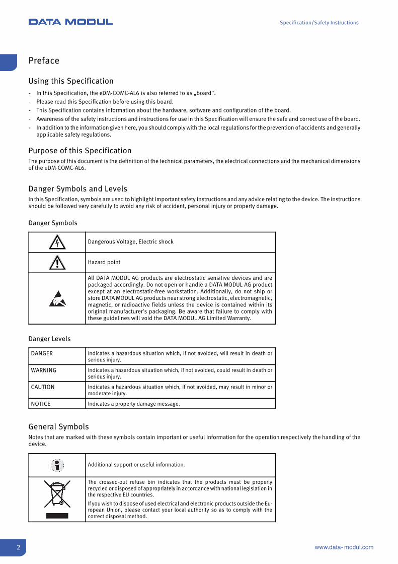
Danger Symbols and LevelsIn this Specification, symbols are used to highlight important safety instructions and any advice relating to the device. The instructionsshould be followed very carefully to avoid any risk of accident, personal injury or property damage.
Danger Symbols
Dangerous Voltage, Electric shock
Hazard point
All DATA MODUL AG products are electrostatic sensitive devices and arepackaged accordingly. Do not open or handle a DATA MODUL AG productexcept at an electrostatic-free workstation. Additionally, do not ship orstore DATA MODUL AG products near strong electrostatic, electromagnetic,magnetic, or radioactive fields unless the device is contained within itsoriginal manufacturer's packaging. Be aware that failure to comply withthese guidelines will void the DATA MODUL AG Limited Warranty.
Danger Levels
DANGER Indicates a hazardous situation which, if not avoided, will result in death orserious injury.
WARNING Indicates a hazardous situation which, if not avoided, could result in death orserious injury.
CAUTION Indicates a hazardous situation which, if not avoided, may result in minor ormoderate injury.
NOTICE Indicates a property damage message.
General SymbolsNotes that are marked with these symbols contain important or useful information for the operation respectively the handling of thedevice.
Additional support or useful information.
The crossed-out refuse bin indicates that the products must be properlyrecycled or disposed of appropriately in accordance with national legislation inthe respective EU countries.
If you wish to dispose of used electrical and electronic products outside the Eu-ropean Union, please contact your local authority so as to comply with thecorrect disposal method.

Specification/Safety Instructions
3www.data- modul.com
Technical SupportDATA MODUL's technicians and engineers are committed to providing the best possible technical support for our customers so thatour products can be easily used and implemented. We request that you first visit our website at www.data-modul.com for the latestdocumentation, utilities and drivers, which have been made available to assist you. If you still require assistance after visiting ourwebsite then contact our technical support department by email at [email protected].
Abbreviations
Term Description
COM Computer On Module
DDC Display Data Channel
EMI Electrical Magnetic Interference
EN European Norm
FFC Flat Foil Cable
HDMI High Definition Multimedia Interface
I²C Inter-Integrated Circuit Bus
LCD Liquid Crystal Display
LVDS Low Voltage Differential Signal
NA Not Available
NC Not Connected
PCB Printed Circuit Board
PWM Pulse Width Modulation
SB Standby
SSP Synchronous Serial Protocol
TBD To be defined
TCON Timing Controller
TMDS Transition Minimized Differential Signalling
TTL Transistor Transistor Logic
UL Underwriter Lab
USB Universal Serial Bus

Specification/Safety Instructions
4 www.data- modul.com
Specifications
Supported Operating SystemsS Microsoft® Windows® 10 (64 bit)
S Microsoft® Windows® 10 IoT Enterprise (64 bit)
S Linux (64 bit Yocto)
EFI / BIOSS UEFI based Firmware using AMI Aptio V core
S Darkboot / Bootlogo support
S Legacy Free Operation
S Boot from external SPI as defined by COM Express specification
S Memory-initialization according to SPD, X.M.P. profiles supported
S LID and Sleep signals supported
S ACPI Wake Events (WOL S3-S5, USB S3-S4, LID S3, PwrBtn S3-S5)
S AC Power Loss configurable by setup
S Spread Spectrum configurable by setup, default ON
S ACPI 6.0
S DATA MODUL family feature: Embedded Controller specification
APIS eAPI as defined by COM Express
S Data Modul specific extension to eAPI
ToolsS BIOS update tool for EFI shell
S BIOS modification tool (for ROM file and running system to extract setup-settings)
S FPGA update tool for EFI shell
S API test tool
Standards & Certifications
Environmentalism
S 2011/65/EU (of 8. June 2011 directive of the European parliament and of the council on the restriction of the use of certainhazardous substances in electrical and electronic equipment (RoHS))
S 2006/1907/EU (of 18. December 2006 of the European parliament and of the council concerning the Registration, Evaluation,Authorisation and Restriction of Chemicals (REACH))
S 2012/19/EC (of 04. July 2012 directive of the European parliament and of the council on waste electrical and electronic equipment(WEEE))
S The board is designed and manufactured to meet ISO 14001.
S The packing complies with directive 1994/62/EU.
EMC StandardsEMI/EMC: according to EN55022
Electrical Safety
Designed to meet EN60950 and UL60950.
Shock & Vibration
Shock and Vibration according to IEC/EN60068-2-6 and IEC/EN60068-2-27.
Specification/Safety Instructions
5www.data- modul.com
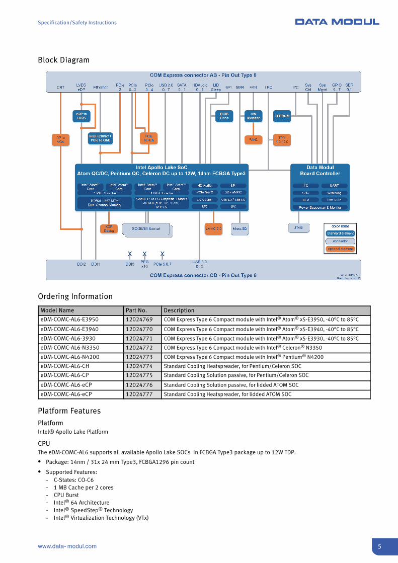
Block Diagram
Ordering Information
Model Name Part No. Description
eDM-COMC-AL6-E3950 12024769 COM Express Type 6 Compact module with Intel® Atom® x5-E3950, -40°C to 85°C
eDM-COMC-AL6-E3940 12024770 COM Express Type 6 Compact module with Intel® Atom® x5-E3940, -40°C to 85°C
eDM-COMC-AL6-3930 12024771 COM Express Type 6 Compact module with Intel® Atom® x5-E3930, -40°C to 85°C
eDM-COMC-AL6-N3350 12024772 COM Express Type 6 Compact module with Intel® Celeron® N3350
eDM-COMC-AL6-N4200 12024773 COM Express Type 6 Compact module with Intel® Pentium® N4200
eDM-COMC-AL6-CH 12024774 Standard Cooling Heatspreader, for Pentium/Celeron SOC
eDM-COMC-AL6-CP 12024775 Standard Cooling Solution passive, for Pentium/Celeron SOC
eDM-COMC-AL6-eCP 12024776 Standard Cooling Solution passive, for lidded ATOM SOC
eDM-COMC-AL6-eCP 12024777 Standard Cooling Heatspreader, for lidded ATOM SOC
Platform Features
PlatformIntel® Apollo Lake Platform
CPUThe eDM-COMC-AL6 supports all available Apollo Lake SOCs in FCBGA Type3 package up to 12W TDP.
S Package: 14nm / 31x 24 mm Type3, FCBGA1296 pin count
S Supported Features:- C-States: CO-C6- 1 MB Cache per 2 cores- CPU Burst- Intel® 64 Architecture- Intel® SpeedStep® Technology- Intel® Virtualization Technology (VTx)

Specification/Safety Instructions
6 www.data- modul.com
S Security Features:- Security Engine- Verified / Security Boot- Intel® Dynamic Application Loader (DAL)- Advanced Encryption Standard New Instructions (Intel® AES-NI)
S Real-time:- Prevention of cache collision- Virtual Channel functionality to CPU edge- Memory Arbiter QOS between CPU & VC- Precision Time Management support (Core Time Stamp Counter & PCIe clock synchronization)
Memory
S Two SO-DIMM sockets
S Memory type: DDR3L
S Speed: up to 1866 MT/s
S Size: up to 16 GB (2 x 8 GB)
Graphics & Media
S GFX type: Intel® HD Graphics Gen 9
S Class: up to 18 EUs
S Display Pipes: 3 independent
S Video Decode: 4k for HEVC, H.264, VP9
S Video Encode: 4k for HEVC, H.264, VP9
S Imaging: 4 Vector Unit Image Processing
S Hardware Acceleration: OpenGL 4.2, DirectX12, OpenCL 2.0
IOS 4 x USB 3.0, 8 x USB 2.0
S 2 x SATA 6Gb/s
S 4 x SATA 3.0
S 1 x SDIO 3.0, 1 x SDXC for microSD socket
S 4 x PCIe(CPU Ports 0/1/2/3 PCIe Gen1/2 compliant Option PCIe Switch: Ports 2/3/4 PCIe Gen1 compliant, Gen2 compliant with restrictionby PEX8605 (ClockJitter)), 1 x used for Gigabit LAN
S Optional PCIe Switch for total 6 x PCIe Gen2
S SPI for external boot flash
S LPC for Embedded Controller / TPM / external SIO
S 8 GPIOs with optional muxed functions:PWM, UART0 (or 1 if counting from 1) DTR/DSR/RTS/CTS, external WD-Kick, I2C
S Intel HD Audio supporting 2 external codecs
S 2 x UART
LAN
Intel®i210 (Industrial) / i211 (Commercial) Gigabit Ethernet Controller with SDP support.
Specification/Safety Instructions
7www.data- modul.com
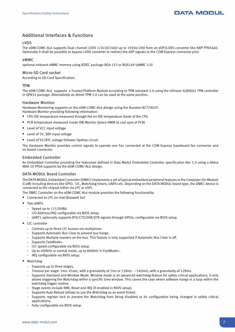
Additional Interfaces & Functions
LVDSThe eDM-COMC-AL6 supports Dual channel LVDS 1/2x18/24bit up to 1920x1200 from an eDP2LVDS converter like NXP PTN3460.Optionally it shall be possible to bypass LVDS converter to redirect the eDP signals to the COM Express connector pins.
eMMCoptional onboard eMMC memory using JEDEC package BGA-153 or BGA169 (eMMC 5.0)
Micro-SD Card socketAccording to SD-Card Specification.
TPMThe eDM-COMC-AL6 supports a Trusted Platform Module according to TPM standard 2.0 using the Infineon SLB9665 TPM controllerin QFN32 package. Alternatively an Atmel-TPM 2.0 can be used at the same position.
Hardware MonitorHardware Monitoring supports on the eDM-COMC-AL6 design using the Nuvoton NCT7802Y.Hardware Monitor providing following information:S CPU DIE temperature measured through the on-DIE temperature diode of the CPU
S PCB temperature measured inside HW Monitor (place HWM at cool spot of PCB)
S Level of VCC input voltage
S Level of 5V_SBY input voltage
S Level of VCCRTC voltage follower OpAmp circuit.
The Hardware Monitor provides control signals to operate one Fan connected at the COM Express baseboard fan connector andon-board Connector.
Embedded ControllerAn Embedded Controller providing the featureset defined in Data Modul Embedded Controller specification Rev 1.0 using a AlteraMAX-10 FPGA supports by the eDM-COMC-AL6 design.
DATA MODUL Board ControllerThe DATA MODUL Embedded Controller (DMEC) implements a set of typical embedded peripheral features in the Computer-On-Module(CoM) including devices like GPIO, I2C, Watchdog timers, UARTs etc. Depending on the DATA MODUL board type, the DMEC device isconnected to the chipset either via LPC or eSPI.The DMEC Controller on the eDM-COMC-AL6 module provides the following functionality:S Connected to LPC on Intel Braswell SoC
S Two UARTs
- Speed up to 115200Bd- I/O Address/IRQ configurable via BIOS setup.- UART1 optionally supports RTS/CTS/DSR/DTR signals through GPIOs, configurable via BIOS setup.
S I2C controller
- Controls up to three I2C busses via multiplexer.- Supports Automatic Bus Clear to prevent bus hangs.- Supports Multiple masters on the bus. This feature is only supported if Automatic Bus Clear is off.- Supports FastMode+.- I2C speed configurable via BIOS setup.- Up to 400kHz in normal mode, up to 800kHz in FastMode+.- IRQ configurable via BIOS setup.
S Watchdog
- Supports up to three stages.- Timeout per stage: 1ms- 65sec, with a granularity of 1ms or 128ms - ~140min, with a granularity of 128ms.- Supports Standard and Window Mode. Window mode is an advanced watchdog feature for safety critical applications. It only
allows triggering the Watchdog within a specific time window. This covers the case where software hangs in a loop within thewatchdog trigger routine.
- Stage events include NMI, Reset and IRQ (if enabled in BIOS setup).- Supports Auto Reload (allows to use the Watchdog as an event ticker).- Supports register lock to prevent the Watchdog from being disabled or its configuration being changed in safety critical
applications.- Fully configurable via BIOS setup.

Specification/Safety Instructions
8 www.data- modul.com
S COM Express GPIOs:
- Supports eight bi-directional GPIOs.- Initial state (In/Out, High/Low, set during early POST) can be configured via BIOS setup.- Capable to generate IRQ events (if IRQ enabled in BIOS setup). For details on how to enable IRQ generation please refer to the
DMEC Functional Specification.- Additional GPIO function configurable via BIOS setup:
H GPIO2: GPIO or UART1 DSRH GPIO4: GPIO or UART1 CTS or PWM0H GPIO5: GPIO or WD Kick Input or UART1 RTS or PWM1H GPIO6: GPIO or I2C2 CL or UART1 DTRH GPIO7: GPIO or I2C2 SDA.
S PWM controller
- Supports either two independent 8Bit channels or one 16 Bit channel for higher resolution for example in DAC applications.- Left or center aligned PWM output- Programmable period and double buffered duty cycle registers- Configurable output polarity- Wide range PWM period configurable per channel via programmable pre-scaler”.
Most common features are accessible through eApi function calls. eApi support and drivers for the DMEC device are available forWindows and Linux. For details on the DMEC register layout please refer to the DMEC Functional Specification which is available fromDATA MODUL on request.
OnModule Memory
An 16 MByte SPI in SO-8 package flash to store EFI and setup configuration shall be used on the eDM-COMC-AL6 design.One 32 kBit I2C EEPROM configured to address A0/A1 is connected to the fast I2C bus of the Embedded Controller and also to the I2Cinterface of the COM Express connector.
Environmental Specification
The eDM-COMC-AL6 is able to be operated and stored under the following environmental conditions:
S Temperature (operating): 0°C … +60°C (commercial grade)
S Temperature (operating): -40°C ... +85°C (industrial grade)
S Temperature (storage): -40°C … +85°C
S Relative humidity: < 80%
S Tolerable air pressure: > 708 hPa (approx. altitude 2000m)
Power Supply
Input Voltage
S VCC: 12.0 V± 5%
S 5V_SBY: 5.0 V± 5%
S Modes: ATX Mode or VCC only without 5V_SBY
Specifications
S Voltage Ripple: max. 100mV peak to peak 0 … 20 MHz
S Rise Time Specification: 0.1 … 20ms from input voltage < 10% nominal VCC
S Max. allowed Inrush Current 5V_SBY: 2AVCC: 5A
Power Features
S Reset Button BehaviorModule resets immediately when reset button is pressed in S0 state.Module stays in reset condition when reset button is pressed and hold in any system state < S0.
Specification/Safety Instructions
9www.data- modul.com
S Power Button BehaviorA push of the power button power up the system to S0 if it is in S5/S3 state or shutdown to S5 if it is in S0 state. Operating systemhandle the power button event depending on the driver settings.Push and hold the power button >4s (power button override) shutdown the system into S5 independent of the other settings.
Interfaces / Connectors
COM Express connector, type 6 pin-out
S According COM Express specification Rev. 2.1.
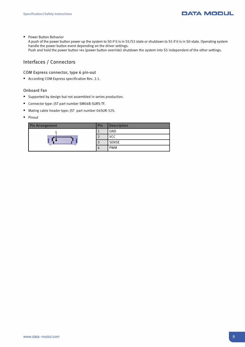
Onboard Fan
S Supported by design but not assembled in series production.
S Connector type: JST part number SM04B-SURS-TF.
S Mating cable header type: JST part number 04SUR-32S.
S Pinout
Pin Arrangement Pin Description
1 1 GND
2 VCC
3 SENSE
4 PWM
Specification/Safety Instructions
10 www.data- modul.com
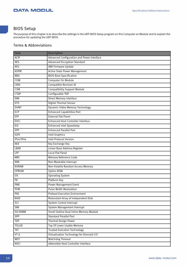
BIOS SetupThe purpose of this chapter is to describe the settings in the UEFI BIOS Setup program on this Computer on Module and to explain theprocedure for updating the UEFI BIOS.
Terms & Abbreviations
Term Description
ACPI Advanced Configuration and Power Interface
AES Advanced Encryption Standard
AFU AMI Firmware Update
ASPM Active State Power Management
BBS BIOS Boot Specification
COM Computer On Module
CRID Compatible Revision ID
CSM Compatibility Support Module
CTDP Configurable TDP
DMI Direct Memory Interface
DTS Digital Thermal Sensor
DVMT Dynamic Video Memory Technology
ECP Enhanced Capabilities Port
EFP External Flat Panel
EHCI Enhanced Host Controller Interface
EIS Enhanced Intel Speedstep
EPP Enhanced Parallel Port
IGFX Intel Graphics
IPv4/IPv6 Intel Protocol Version
KEK Key Exchange Key
LBAR Linear Base Address Register
LFP Local Flat Panel
MRC Memory Reference Code
NMI Non-Maskable Interrupt
NVRAM Non-Volatile Random-Access Memory
OPROM Option ROM
OS Operating System
PK Platform Key
PME Power Management Event
PVM Pulse Width Modulation
PXE Preboot Execution Environment
RAID Redundant Array of Independent Disk
SCI System Control Interrupt
SMI System Management Interrupt
SO-DIMM Small Outline Dual Inline Memory Module
SPP Standard Parallel Port
TDP Thermal Design Power
TOLUD Top Of Lower Usable Memory
TXT Trusted Execution Technology
VT-d Virtualization Technology for Directed I/O
WDT Watchdog Timeout
XHCI eXtensible Host Controller Interface
Specification/Safety Instructions
11www.data- modul.com
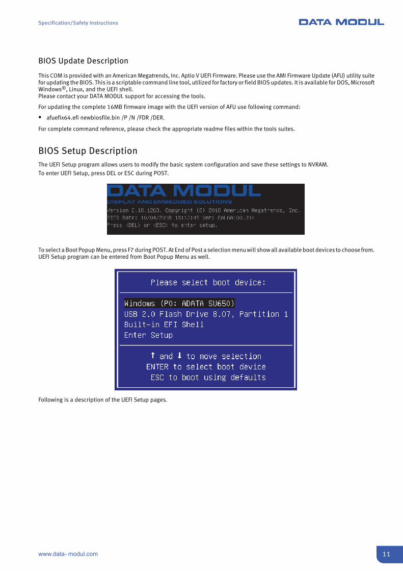
BIOS Update Description
This COM is provided with an American Megatrends, Inc. Aptio V UEFI Firmware. Please use the AMI Firmware Update (AFU) utility suitefor updating the BIOS. This is a scriptable command line tool, utilized for factory or field BIOS updates. It is available for DOS, MicrosoftWindows®, Linux, and the UEFI shell.Please contact your DATA MODUL support for accessing the tools.
For updating the complete 16MB firmware image with the UEFI version of AFU use following command:
S afuefix64.efi newbiosfile.bin /P /N /FDR /DER.
For complete command reference, please check the appropriate readme files within the tools suites.
BIOS Setup DescriptionThe UEFI Setup program allows users to modify the basic system configuration and save these settings to NVRAM.
To enter UEFI Setup, press DEL or ESC during POST.
To select a Boot Popup Menu, press F7 during POST. At End of Post a selection menu will show all available boot devices to choose from.UEFI Setup program can be entered from Boot Popup Menu as well.
Following is a description of the UEFI Setup pages.
Specification/Safety Instructions
12 www.data- modul.com
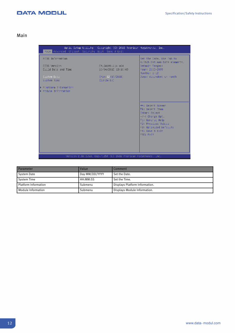
Main
Parameter Value Comment
System Date Day MM/DD/YYYY Set the Date.
System Time HH:MM:SS Set the Time.
Platform Information Submenu Displays Platform Information.
Module Information Submenu Displays Module Information.
Specification/Safety Instructions
13www.data- modul.com
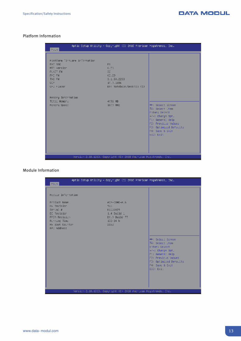
Platform Information
Module Information
Specification/Safety Instructions
14 www.data- modul.com
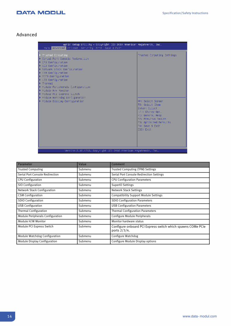
Advanced
Parameter Value Comment
Trusted Computing Submenu Trusted Computing (TPM) Settings
Serial Port Console Redirection Submenu Serial Port Console Redirection Settings
CPU Configuration Submenu CPU Configuration Parameters
SIO Configuration Submenu SuperIO Settings
Network Stack Configuration Submenu Network Stack Settings
CSM Configuration Submenu Compatibility Support Module Settings
SDIO Configuration Submenu SDIO Configuration Parameters
USB Configuration Submenu USB Configuration Parameters
Thermal Configuration Submenu Thermal Configuration Parameters
Module Peripherals Configuration Submenu Configure Module Peripherals
Module H/W Monitor Submenu Monitor hardware status
Module PCI Express Switch Submenu Configure onboard PCI Express switch which spawns COMe PCIeports 2/3/4.
Module Watchdog Configuration Submenu Configure Watchdog
Module Display Configuration Submenu Configure Module Display options

Specification/Safety Instructions
15www.data- modul.com
CPU Configuration
Parameter Value Comment
CPU Information Submenu CPU information and features.
CPU Power Management Submenu CPU power management options.
Active Processor Cores EnabledDisabled
Number of cores to enable in each processor package.
Intel Virtualization Technology EnabledDisabled
When enabled, a VMM can utilize the additional hardware capabilitiesprovided by Vanderpool Technology.
VT-d EnabledDisabled
Enable/Disable CPU VT-d
Bi-directional PROCHOT EnabledDisabled
When a processor thermal sensor trips (either core), the PROCHOT# will bedriven.If bi-direction is enabled, external agents can drive PROCHOT# to throttlethe processor.
Thermal Monitor EnabledDisabled
Enable/Disable Thermal Monitor
Monitor Mwait AutoEnabledDisabled
Enable/Disable Monitor Mwait
P-STATE Coordination HW_ALLSW_ALLSW_ANY
Change P-STATE Coordination type.
DTS EnabledDisabled
Enabled: ACPI thermal management uses DTS SMM mechanism to obtainCPU temperature values.Disabled: DTS SMM and ACPI thermal management is disabled.
Specification/Safety Instructions
16 www.data- modul.com
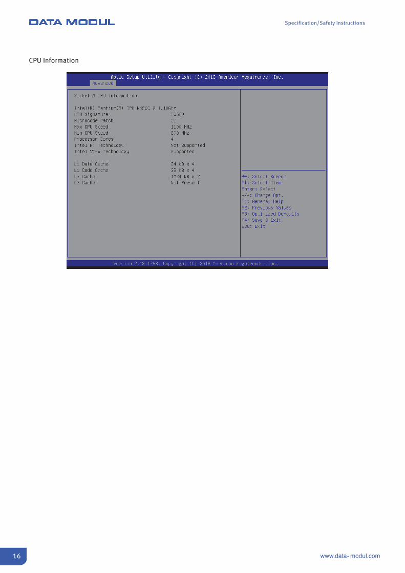
CPU Information
Specification/Safety Instructions
17www.data- modul.com
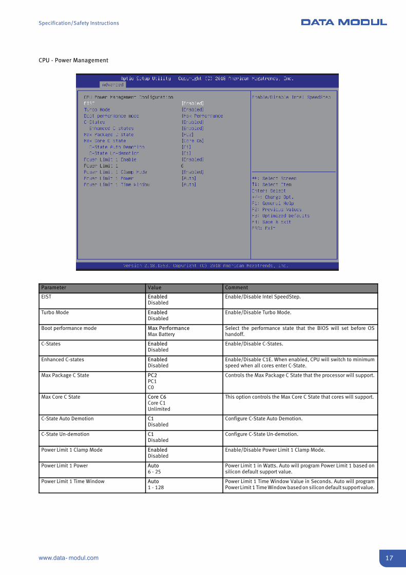
CPU - Power Management
Parameter Value Comment
EIST EnabledDisabled
Enable/Disable Intel SpeedStep.
Turbo Mode EnabledDisabled
Enable/Disable Turbo Mode.
Boot performance mode Max PerformanceMax Battery
Select the performance state that the BIOS will set before OShandoff.
C-States EnabledDisabled
Enable/Disable C-States.
Enhanced C-states EnabledDisabled
Enable/Disable C1E. When enabled, CPU will switch to minimumspeed when all cores enter C-State.
Max Package C State PC2PC1C0
Controls the Max Package C State that the processor will support.
Max Core C State Core C6Core C1Unlimited
This option controls the Max Core C State that cores will support.
C-State Auto Demotion C1Disabled
Configure C-State Auto Demotion.
C-State Un-demotion C1Disabled
Configure C-State Un-demotion.
Power Limit 1 Clamp Mode EnabledDisabled
Enable/Disable Power Limit 1 Clamp Mode.
Power Limit 1 Power Auto6 - 25
Power Limit 1 in Watts. Auto will program Power Limit 1 based onsilicon default support value.
Power Limit 1 Time Window Auto1 - 128
Power Limit 1 Time Window Value in Seconds. Auto will programPower Limit 1 Time Window based on silicon default supportvalue.
Specification/Safety Instructions
18 www.data- modul.com
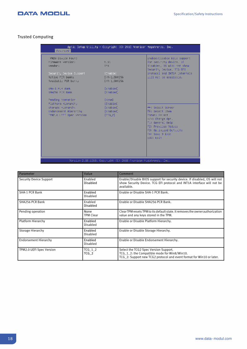
Trusted Computing
Parameter Value Comment
Security Device Support EnabledDisabled
Enable/Disable BIOS support for security device. If disabled, OS will notshow Security Device. TCG EFI protocol and INT1A interface will not beavailable.
SHA-1 PCR Bank EnabledDisabled
Enable or Disable SHA-1 PCR Bank.
SHA256 PCR Bank EnabledDisabled
Enable or Disable SHA256 PCR Bank.
Pending operation NoneTPM Clear
Clear TPMresets TPMto its default state. It removes the ownerauthorizationvalue and any keys stored in the TPM.
Platform Hierarchy EnabledDisabled
Enable or Disable Platform Hierarchy.
Storage Hierarchy EnabledDisabled
Enable or Disable Storage Hierarchy.
Endorsement Hierarchy EnabledDisabled
Enable or Disable Endorsement Hierarchy.
TPM2.0 UEFI Spec Version TCG_1_2TCG_2
Select the TCG2 Spec Version Support.TCG_1_2: the Compatible mode for Win8/Win10.TCG_2: Support new TCG2 protocol and event format for Win10 or later.
Specification/Safety Instructions
19www.data- modul.com
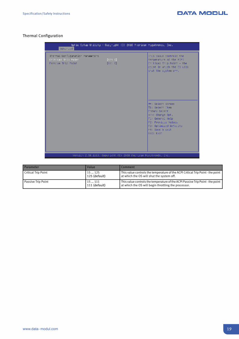
Thermal Configuration
Parameter Value Comment
Critical Trip Point 15 … 125125 (default)
This value controls the temperature of the ACPI Critical Trip Point - the pointat which the OS will shut the system off.
Passive Trip Point 15 … 111111 (default)
This value controls the temperature of the ACPI Passive Trip Point - the pointat which the OS will begin throttling the processor.

Specification/Safety Instructions
20 www.data- modul.com
SDIO Configuration
Parameter Value Comment
SDIO Access Mode AutoADMASDMAPIO
Auto Option: Access SD device in DMA mode if controller supports it,otherwise in PIO mode.DMA Option: Access SD device in DMA mode.PIO Option: Access SD device in PIO mode.
Device Configuration AutoFloppyForce FDDHard Disk
Mass storage device emulation type. ‘AUTO’ enumerates devices less than530MB as floppies. Forced FDD option can be used to force HDD formatteddrive to boot as FDD.

Specification/Safety Instructions
21www.data- modul.com
SIO Configuration
Parameter Value Comment
Serial Port 1 Submenu
View and set basic properties of the SIO logical device. Like IO base, IRQrange, DMA channel and device mode.
Serial Port 2 Submenu
Parallel Port Submenu
PS2 Controller (KB&MS) Submenu

Specification/Safety Instructions
22 www.data- modul.com
Serial Port 1 Configuration
Parameter Value Comment
Use This Device EnabledDisabled
Enable or Disable this Logical Device.
Possible Use Automatic SettingsIO=3F8h; IRQ=4IO=2F8hIO=3E8hIO=2E8hIRQ=3,4,5,7,9,10,11,12
Configure Device's Resource settings. New settings will be reflectedon This Setup Page after System restarts.
Specification/Safety Instructions
23www.data- modul.com
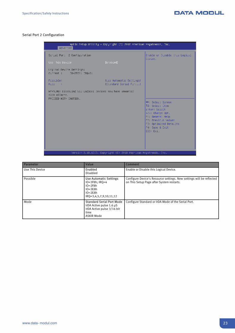
Serial Port 2 Configuration
Parameter Value Comment
Use This Device EnabledDisabled
Enable or Disable this Logical Device.
Possible Use Automatic SettingsIO=3F8h; IRQ=4IO=2F8hIO=3E8hIO=2E8hIRQ=3,4,5,7,9,10,11,12
Configure Device's Resource settings. New settings will be reflectedon This Setup Page after System restarts.
Mode Standard Serial Port ModeIrDA Active pulse 1.6 μSIrDA Active pulse 3/16 bittimeASKIR Mode
Configure Standard or IrDA Mode of the Serial Port.
Specification/Safety Instructions
24 www.data- modul.com
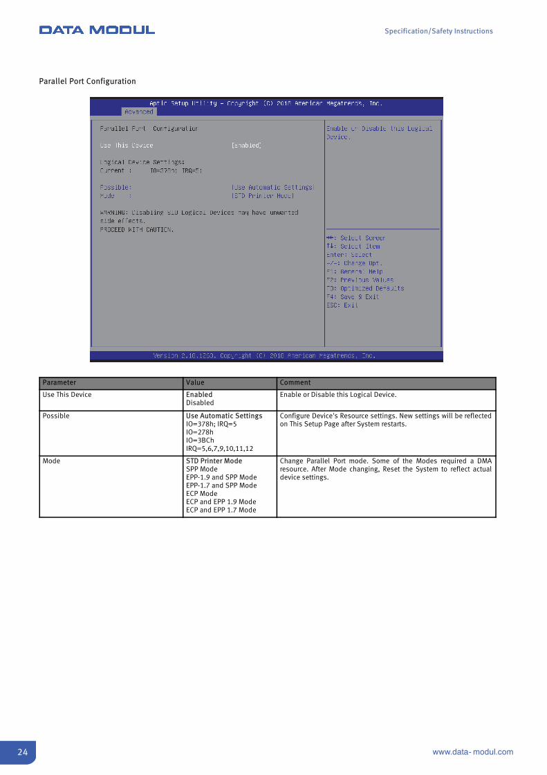
Parallel Port Configuration
Parameter Value Comment
Use This Device EnabledDisabled
Enable or Disable this Logical Device.
Possible Use Automatic SettingsIO=378h; IRQ=5IO=278hIO=3BChIRQ=5,6,7,9,10,11,12
Configure Device's Resource settings. New settings will be reflectedon This Setup Page after System restarts.
Mode STD Printer ModeSPP ModeEPP-1.9 and SPP ModeEPP-1.7 and SPP ModeECP ModeECP and EPP 1.9 ModeECP and EPP 1.7 Mode
Change Parallel Port mode. Some of the Modes required a DMAresource. After Mode changing, Reset the System to reflect actualdevice settings.

Specification/Safety Instructions
25www.data- modul.com
PS2 Controller (KB&MS) Configuration
Parameter Value Comment
Use This Device EnabledDisabled
Enable or Disable this Logical Device.
Possible Use Automatic SettingsIO=60h; IO=64h; IRQ=1
Configure Device's Resource settings. New settings will be reflectedon this Setup Page after System restarts.

Specification/Safety Instructions
26 www.data- modul.com
Serial Port Console Redirection
Parameter Value Comment
Console Redirection EnabledDisabled
Enables/Disables Console Redirection.
Console Redirection Settings Submenu The settings specify how the host computer and the remote computer(which the user is using) will exchange data. Both computers should havethe same or compatible settings.
Legacy Console Redirection Settings Submenu Configure Port for Legacy Console Redirection.

Specification/Safety Instructions
27www.data- modul.com
Console Redirection Settings
Parameter Value Comment
Terminal Type VT100VT100+VT-UTF8ANSI
Emulation:ANSI: Extended ASCII char set.VT100: ASCII char set.VT100+: Extends VT100 to support color, function keys, etc.VT-UTF8: Uses UTF8 encoding to map Unicode chars onto 1 or more bytes.
Bits per second 9600192003840057600115200
Selects serial port transmission speed. The speed must be matched on theother side. Long or noisy lines may require lower speeds.
Data Bits 78
Configures the number of data bits.8 is recommended to easily use the link for file transfer and non-Englishtext transfer.
Parity NoneEvenOddMarkSpace
A parity bit can be sent with the data bits to detect some transmissionerrors.Even: parity bit is 0 if the num of 1's in the data bits is even.Odd: parity bit is 0 if num of 1's in the data bits is odd.Mark: parity bit is always 1.Space: Parity bit is always 0.Mark and Space Parity do not allow for error detection. They can be used asan additional data bit.
Stop Bits 12
Stop bits indicate the end of a serial data packet. (A start bit indicates thebeginning). The standard setting is 1 stop bit. Communication with slowdevices may require more than 1 stop bit.
Flow Control NoneHardware RTS/CTS
Flow control can prevent data loss from buffer overflow. When sendingdata, if the receiving buffers are full, a 'stop' signal can be sent to stopthe data flow. Once the buffers are empty, a 'start' signal can be sent tore-start the flow. Hardware flow control uses two wires to send start/stopsignals.
VT-UTF8 Combo Key Support EnabledDisabled
Enable: VT-UTF8 Combination Key Support for ANSI/VT100 terminals.
Recorder Mode EnabledDisabled
With this mode enabled, only text will be sent. This is to capture Terminaldata.
Resolution 100x31 EnabledDisabled
Enables/Disables extended terminal resolution.

Specification/Safety Instructions
28 www.data- modul.com
Parameter Value Comment
Legacy OS Redirection Resolution 80x2480x25
On Legacy OS, the Number of Rows and Columns supported by redirection.
Putty KeyPad VT100LINUXXTERMR6SCOESCNVT400
Select FunctionKey and KeyPad on Putty.
Redirection After BIOS POST EnabledDisabled
Enabled: Console Redirection is available for Legacy OS.Disabled: Legacy console redirection is disabled before booting to LegacyOS.
Legacy Console Redirection Settings
Parameter Value Comment
Legacy Redirection COM Port COM0COM1COM2COM3
Select a COM Port to use for Legacy OS and Legacy OPROM ConsoleRedirection.
Specification/Safety Instructions
29www.data- modul.com
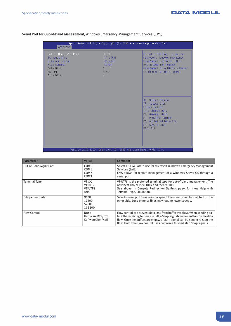
Serial Port for Out-of-Band Management/Windows Emergency Management Services (EMS)
Parameter Value Comment
Out-of-Band Mgmt Port COM0COM1COM2COM3
Select a COM Port to use for Microsoft Windows Emergency ManagementServices (EMS).EMS allows for remote management of a Windows Server OS through aserial port.
Terminal Type VT100VT100+VT-UTF8ANSI
VT-UTF8 is the preferred terminal type for out-of-band management. Thenext best choice is VT100+ and then VT100.See above, in Console Redirection Settings page, for more Help withTerminal Type/Emulation.
Bits per seconds 96001920057600115200
Selects serial port transmission speed. The speed must be matched on theother side. Long or noisy lines may require lower speeds.
Flow Control NoneHardware RTS/CTSSoftware Xon/Xoff
Flow control can prevent data loss from buffer overflow. When sending da-ta, if the receiving buffers are full, a 'stop' signal can be sent to stop the dataflow. Once the buffers are empty, a 'start' signal can be sent to re-start theflow. Hardware flow control uses two wires to send start/stop signals.
Specification/Safety Instructions
30 www.data- modul.com
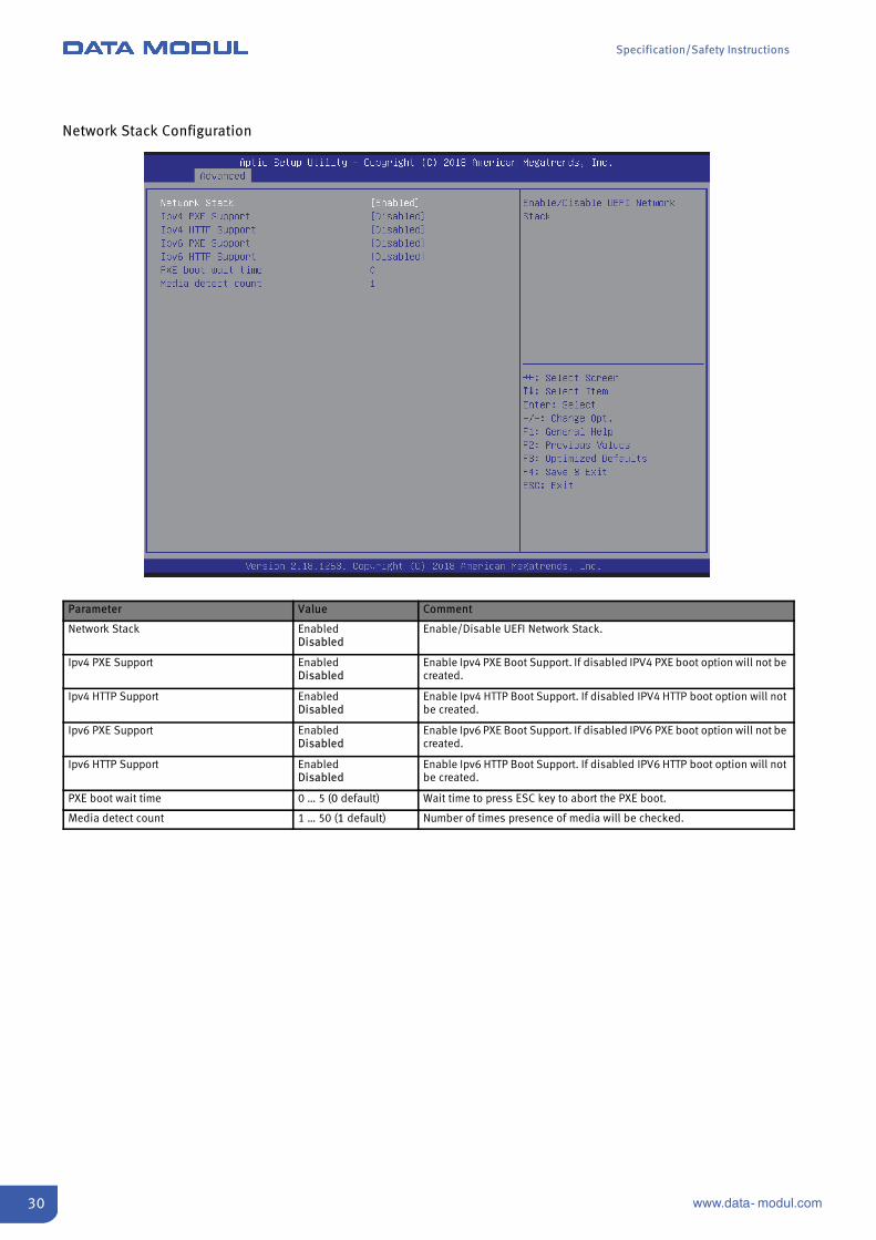
Network Stack Configuration
Parameter Value Comment
Network Stack EnabledDisabled
Enable/Disable UEFI Network Stack.
Ipv4 PXE Support EnabledDisabled
Enable Ipv4 PXE Boot Support. If disabled IPV4 PXE boot option will not becreated.
Ipv4 HTTP Support EnabledDisabled
Enable Ipv4 HTTP Boot Support. If disabled IPV4 HTTP boot option will notbe created.
Ipv6 PXE Support EnabledDisabled
Enable Ipv6 PXE Boot Support. If disabled IPV6 PXE boot option will not becreated.
Ipv6 HTTP Support EnabledDisabled
Enable Ipv6 HTTP Boot Support. If disabled IPV6 HTTP boot option will notbe created.
PXE boot wait time 0 … 5 (0 default) Wait time to press ESC key to abort the PXE boot.
Media detect count 1 … 50 (1 default) Number of times presence of media will be checked.
Specification/Safety Instructions
31www.data- modul.com
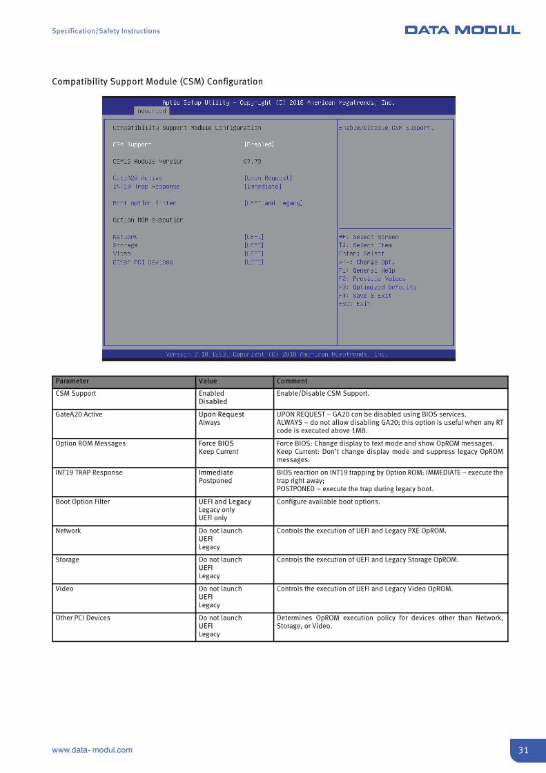
Compatibility Support Module (CSM) Configuration
Parameter Value Comment
CSM Support EnabledDisabled
Enable/Disable CSM Support.
GateA20 Active Upon RequestAlways
UPON REQUEST – GA20 can be disabled using BIOS services.ALWAYS – do not allow disabling GA20; this option is useful when any RTcode is executed above 1MB.
Option ROM Messages Force BIOSKeep Current
Force BIOS: Change display to text mode and show OpROM messages.Keep Current: Don’t change display mode and suppress legacy OpROMmessages.
INT19 TRAP Response ImmediatePostponed
BIOS reaction on INT19 trapping by Option ROM: IMMEDIATE – execute thetrap right away;POSTPONED – execute the trap during legacy boot.
Boot Option Filter UEFI and LegacyLegacy onlyUEFI only
Configure available boot options.
Network Do not launchUEFILegacy
Controls the execution of UEFI and Legacy PXE OpROM.
Storage Do not launchUEFILegacy
Controls the execution of UEFI and Legacy Storage OpROM.
Video Do not launchUEFILegacy
Controls the execution of UEFI and Legacy Video OpROM.
Other PCI Devices Do not launchUEFILegacy
Determines OpROM execution policy for devices other than Network,Storage, or Video.
Specification/Safety Instructions
32 www.data- modul.com
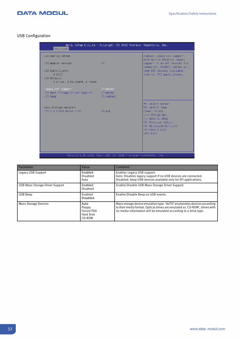
USB Configuration
Parameter Value Comment
Legacy USB Support EnabledDisabledAuto
Enables Legacy USB support.Auto: Disables legacy support if no USB devices are connected.Disabled: Keep USB devices available only for EFI applications.
USB Mass Storage Driver Support EnabledDisabled
Enable/Disable USB Mass Storage Driver Support.
USB Beep EnabledDisabled
Enable/Disable Beep on USB events.
Mass Storage Devices AutoFloppyForced FDDHard DiskCD-ROM
Mass storage device emulation type. 'AUTO' enumerates devices accordingto their media format. Optical drives are emulated as 'CD-ROM', drives withno media information will be emulated according to a drive type.
Specification/Safety Instructions
33www.data- modul.com
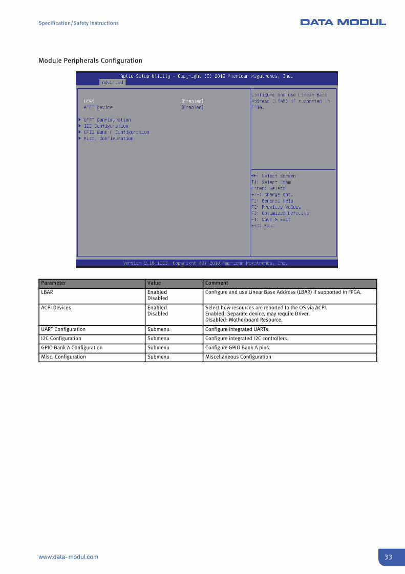
Module Peripherals Configuration
Parameter Value Comment
LBAR EnabledDisabled
Configure and use Linear Base Address (LBAR) if supported in FPGA.
ACPI Devices EnabledDisabled
Select how resources are reported to the OS via ACPI.Enabled: Separate device, may require Driver.Disabled: Motherboard Resource.
UART Configuration Submenu Configure integrated UARTs.
I2C Configuration Submenu Configure integrated I2C controllers.
GPIO Bank A Configuration Submenu Configure GPIO Bank A pins.
Misc. Configuration Submenu Miscellaneous Configuration
Specification/Safety Instructions
34 www.data- modul.com
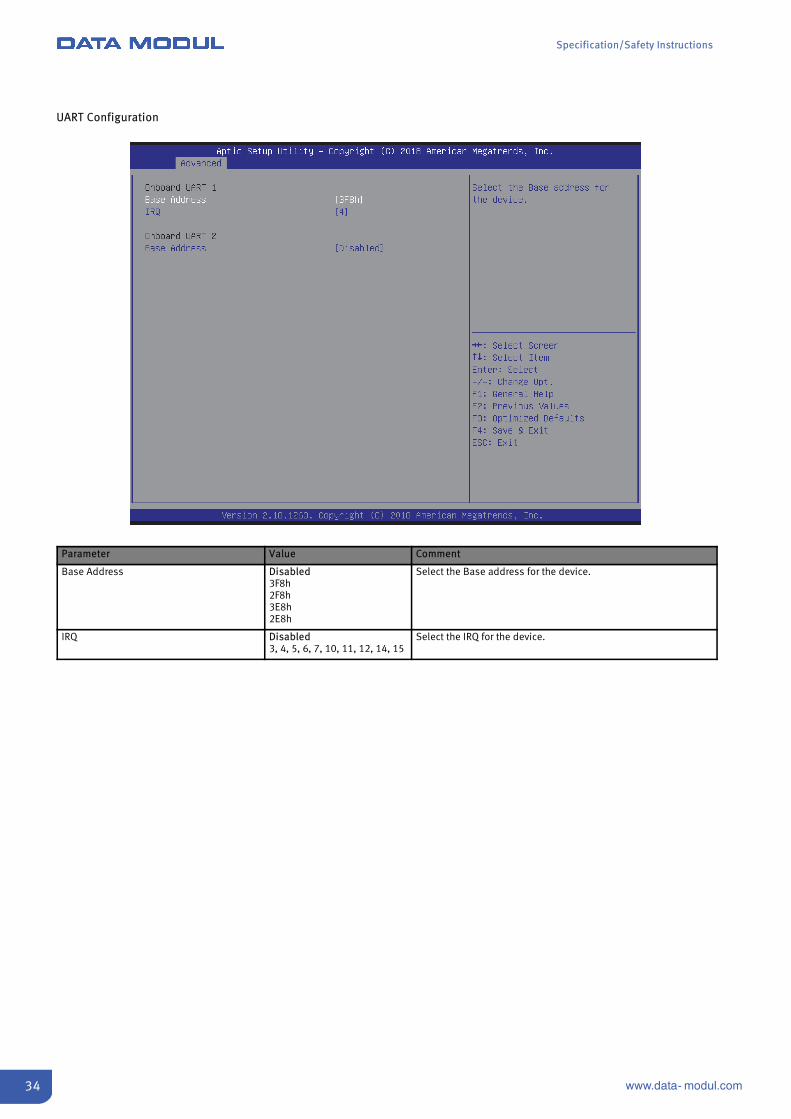
UART Configuration
Parameter Value Comment
Base Address Disabled3F8h2F8h3E8h2E8h
Select the Base address for the device.
IRQ Disabled3, 4, 5, 6, 7, 10, 11, 12, 14, 15
Select the IRQ for the device.
Specification/Safety Instructions
35www.data- modul.com
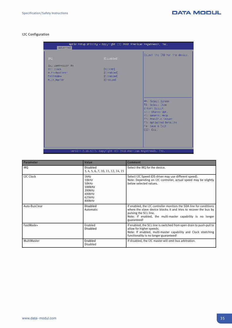
I2C Configuration
Parameter Value Comment
IRQ Disabled3, 4, 5, 6, 7, 10, 11, 12, 14, 15
Select the IRQ for the device.
I2C Clock 1kHz10kHz50kHz100kHz200kHz400kHz625kHz800kHz
Select I2C Speed (OS driver may use different speed).Note: Depending on I2C controller, actual speed may be slightlybelow selected values.
Auto-BusClear DisabledAutomatic
If enabled, the I2C controller monitors the SDA line for conditionswhere the slave device blocks it and tries to recover the bus bypulsing the SCL line.Note: If enabled, the multi-master capability is no longerguaranteed!
FastMode+ EnabledDisabled
If enabled, the SCL line is switched from open drain to push-pull toallow for higher speeds.Note: If enabled, multi-master capability and Clock stretchingfunctionality is no longer guaranteed!
MultiMaster EnabledDisabled
If disabled, the I2C master will omit bus arbitration.
Specification/Safety Instructions
36 www.data- modul.com
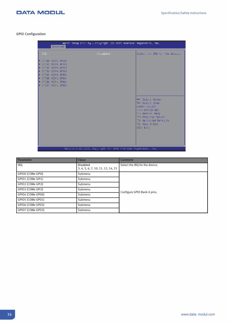
GPIO Configuration
Parameter Value Comment
IRQ Disabled3, 4, 5, 6, 7, 10, 11, 12, 14, 15
Select the IRQ for the device.
GPIO0 (COMe GPI0) Submenu
Configure GPIO Bank A pins.
GPIO1 (COMe GPI1) Submenu
GPIO2 (COMe GPI2) Submenu
GPIO3 (COMe GPI3) Submenu
GPIO4 (COMe GPO0) Submenu
GPIO5 (COMe GPO1) Submenu
GPIO6 (COMe GPO2) Submenu
GPIO7 (COMe GPO3) Submenu

Specification/Safety Instructions
37www.data- modul.com
GPIO0, GPIO1, GPIO3
Parameter Value Comment
Usage GPIO Configure GPIO usage.
Direction In (default for GPIO0-3)Out (default for GPIO5-7)
Configure GPIO direction.
Level Low-LevelHigh-Level
Configure GPIO initial level.

Specification/Safety Instructions
38 www.data- modul.com
GPIO2
Parameter Value Comment
Usage GPIOUART1 DSR
Configure GPIO usage.
Direction In (default for GPIO0-3)Out (default for GPIO5-7)
Configure GPIO direction.
Level Low-LevelHigh-Level
Configure GPIO initial level.
Specification/Safety Instructions
39www.data- modul.com
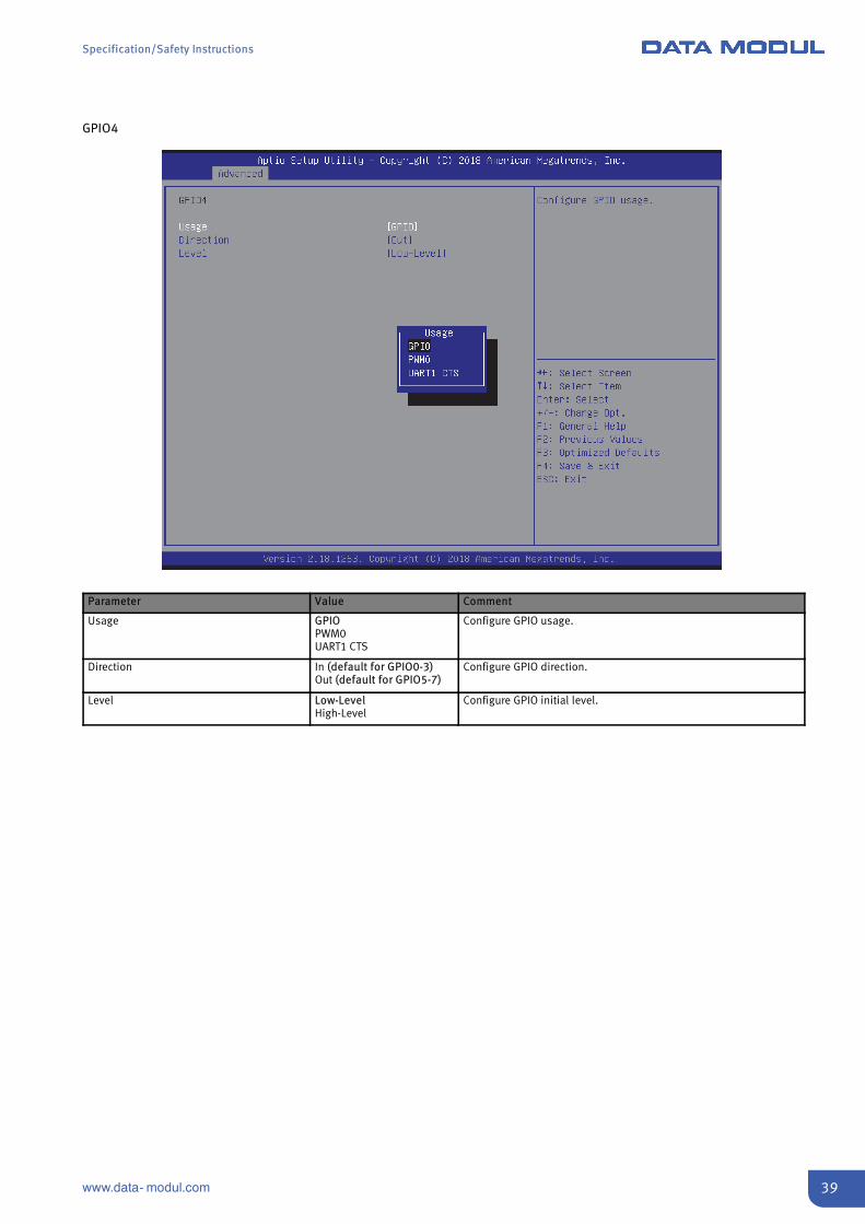
GPIO4
Parameter Value Comment
Usage GPIOPWM0UART1 CTS
Configure GPIO usage.
Direction In (default for GPIO0-3)Out (default for GPIO5-7)
Configure GPIO direction.
Level Low-LevelHigh-Level
Configure GPIO initial level.
Specification/Safety Instructions
40 www.data- modul.com
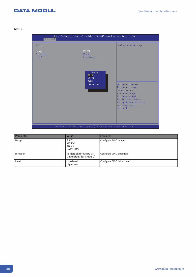
GPIO5
Parameter Value Comment
Usage GPIOWD KickPWM1UART1 RTS
Configure GPIO usage.
Direction In (default for GPIO0-3)Out (default for GPIO5-7)
Configure GPIO direction.
Level Low-LevelHigh-Level
Configure GPIO initial level.

Specification/Safety Instructions
41www.data- modul.com
GPIO6
Parameter Value Comment
Usage GPIOI2C2 SCLUART1 DTR
Configure GPIO usage.
Direction In (default for GPIO0-3)Out (default for GPIO5-7)
Configure GPIO direction.
Level Low-LevelHigh-Level
Configure GPIO initial level.

Specification/Safety Instructions
42 www.data- modul.com
GPIO7
Parameter Value Comment
Usage GPIOI2C2 SDA
Configure GPIO usage.
Direction In (default for GPIO0-3)Out (default for GPIO5-7)
Configure GPIO direction.
Level Low-LevelHigh-Level
Configure GPIO initial level.

Specification/Safety Instructions
43www.data- modul.com
Misc. Configuration
Parameter Value Comment
Watchdog IRQ Disabled3, 4, 5, 6, 7, 10, 11,12, 14, 15
Select the IRQ for the Watchdog device. IRQ selection will be available inthe Watchdog menu after reboot.
Specification/Safety Instructions
44 www.data- modul.com
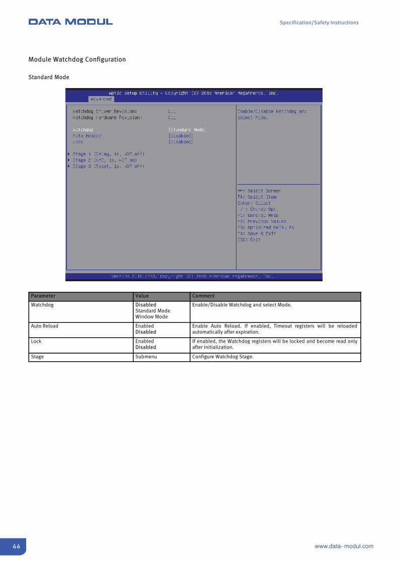
Module Watchdog Configuration
Standard Mode
Parameter Value Comment
Watchdog DisabledStandard ModeWindow Mode
Enable/Disable Watchdog and select Mode.
Auto Reload EnabledDisabled
Enable Auto Reload. If enabled, Timeout registers will be reloadedautomatically after expiration.
Lock EnabledDisabled
If enabled, the Watchdog registers will be locked and become read onlyafter initialization.
Stage Submenu Configure Watchdog Stage.

Specification/Safety Instructions
45www.data- modul.com
Stage Configuration
Parameter Value Comment
Stage Action DisabledDelayResetNMIIRQ
Select Stage Action on timeout.For choosing IRQ, enable Interrupt within Menu ‘Module PeripheralsConfiguration’ – ‘Misc. Configuration’ – Watchdog IRQ’ first, then Save andReboot to Setup.
Timeout 1 … 65535 (1 default) Select the timeout value for the stage.
WDT# EnabledDisabled
Assert WDT# signal to Baseboard.

Specification/Safety Instructions
46 www.data- modul.com
Window Mode
Parameter Value Comment
Watchdog DisabledStandard ModeWindow Mode
Enable/Disable Watchdog and select Mode.
Lock EnabledDisabled
If enabled, the Watchdog registers will be locked and become read onlyafter initialization.
Delay Submenu Enable/Disable Watchdog and select Mode.
Window Closed Period Submenu Trigger events during this period will be treated as error and cause the time-out event selected in the Window Open Stage.
Window Opened Period Submenu Trigger events during this period will reload the watchdog timer andtransition the internal state machine to the Window Closed Stage.

Specification/Safety Instructions
47www.data- modul.com
Module H/W Monitor
Parameter Value Comment
Temperature Unit CelsiusFahrenheit
Select temperature scale Celsius or Fahrenheit.
Configure Fan Sensors Submenu Configure Fan parameters.
Specification/Safety Instructions
48 www.data- modul.com
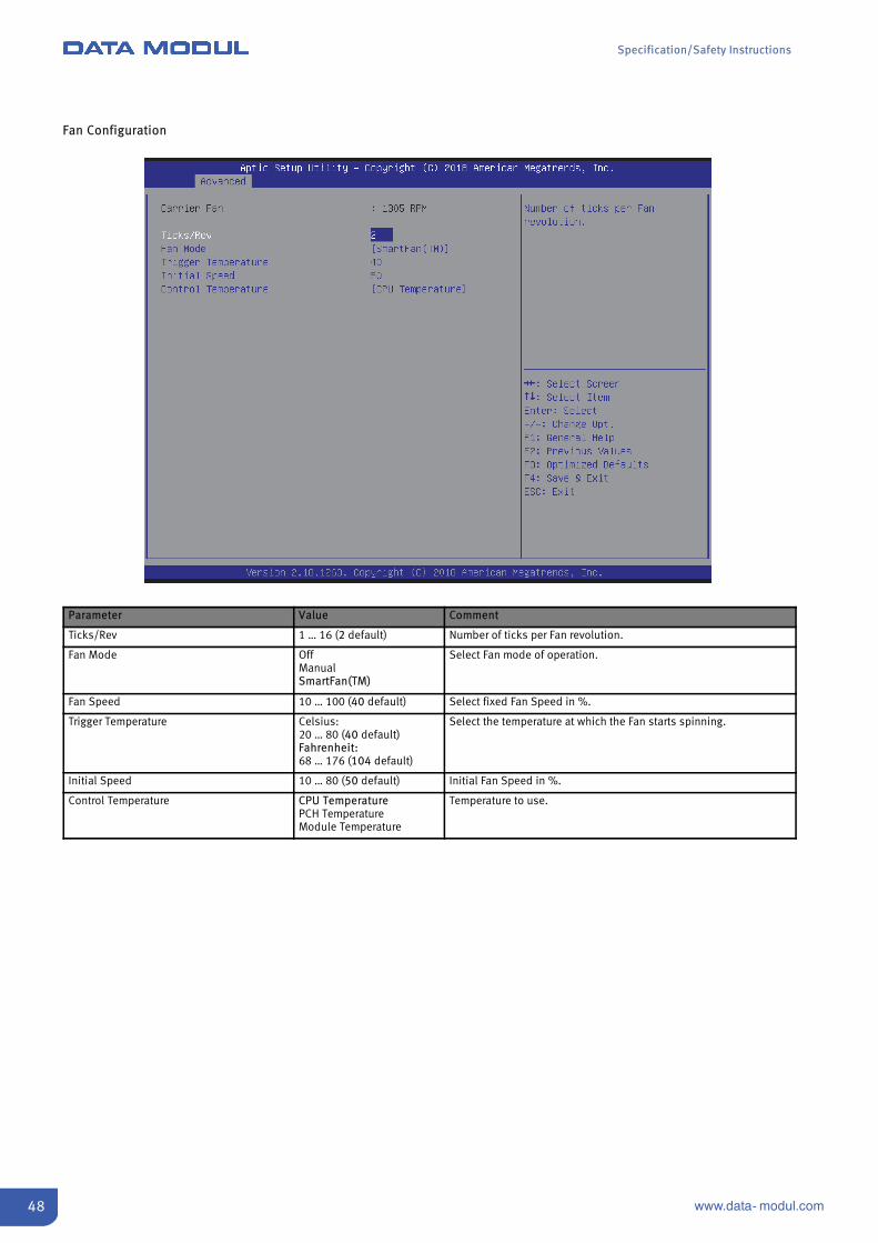
Fan Configuration
Parameter Value Comment
Ticks/Rev 1 … 16 (2 default) Number of ticks per Fan revolution.
Fan Mode OffManualSmartFan(TM)
Select Fan mode of operation.
Fan Speed 10 … 100 (40 default) Select fixed Fan Speed in %.
Trigger Temperature Celsius:20 … 80 (40 default)Fahrenheit:68 … 176 (104 default)
Select the temperature at which the Fan starts spinning.
Initial Speed 10 … 80 (50 default) Initial Fan Speed in %.
Control Temperature CPU TemperaturePCH TemperatureModule Temperature
Temperature to use.
Specification/Safety Instructions
49www.data- modul.com
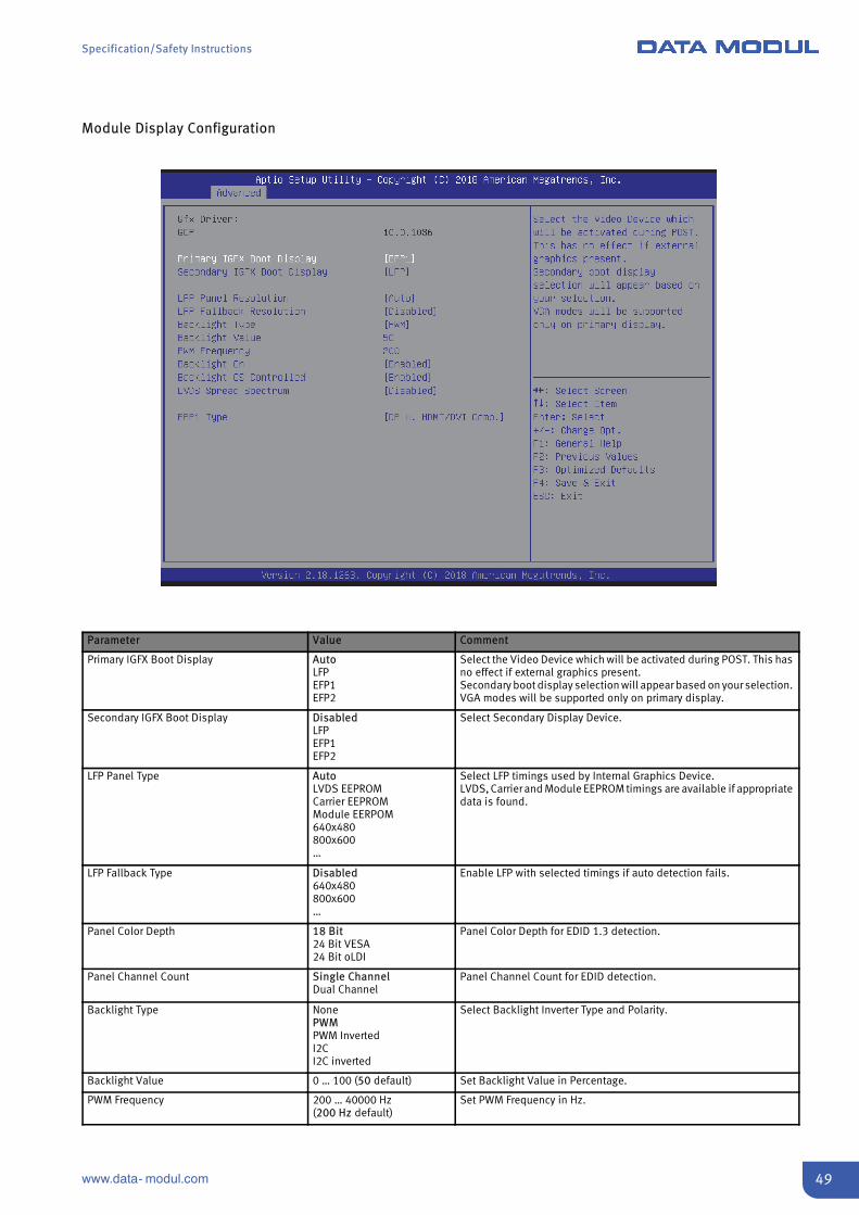
Module Display Configuration
Parameter Value Comment
Primary IGFX Boot Display AutoLFPEFP1EFP2
Select the Video Device which will be activated during POST. This hasno effect if external graphics present.Secondary boot display selection will appear based on your selection.VGA modes will be supported only on primary display.
Secondary IGFX Boot Display DisabledLFPEFP1EFP2
Select Secondary Display Device.
LFP Panel Type AutoLVDS EEPROMCarrier EEPROMModule EERPOM640x480800x600…
Select LFP timings used by Internal Graphics Device.LVDS, Carrier and Module EEPROM timings are available if appropriatedata is found.
LFP Fallback Type Disabled640x480800x600…
Enable LFP with selected timings if auto detection fails.
Panel Color Depth 18 Bit24 Bit VESA24 Bit oLDI
Panel Color Depth for EDID 1.3 detection.
Panel Channel Count Single ChannelDual Channel
Panel Channel Count for EDID detection.
Backlight Type NonePWMPWM InvertedI2CI2C inverted
Select Backlight Inverter Type and Polarity.
Backlight Value 0 … 100 (50 default) Set Backlight Value in Percentage.
PWM Frequency 200 … 40000 Hz(200 Hz default)
Set PWM Frequency in Hz.

Specification/Safety Instructions
50 www.data- modul.com
Parameter Value Comment
Backlight On EnabledAt the End of Post
Configure if LVDS Backlight should be set when panel is powered, orinhibit until End Of Post.
Backlight OS Controlled EnabledDisabled
Configure if PWM values can be overridden by OS Power Options.
LVDS Spread Spectrum Disabled0.5 %1.0 %1.5 %2.0 %2.5 %
Set LVDS Center Spreading.
EFP Type HDMI/DVIDP w. HDMI/DVI Comp.DP only
Select the type of the EFP.

Specification/Safety Instructions
51www.data- modul.com
Module PCI Express Switch
Parameter Value Comment
PEX8605 Upstream Port Submenu Configure PCIe Switch Upstream port.

Specification/Safety Instructions
52 www.data- modul.com
PEX8605 Upstream Port
Parameter Value Comment
PEX8605 Upstream Port AutoEnabledDisabled
Enable/ Disable Port.
ASPM DisabledL0sL1L0sL1Auto
PCI Express Active State Power Management settings.
Max. Payload Size 128 Bytes256 Bytes
Select maximum payload size.
Specification/Safety Instructions
53www.data- modul.com
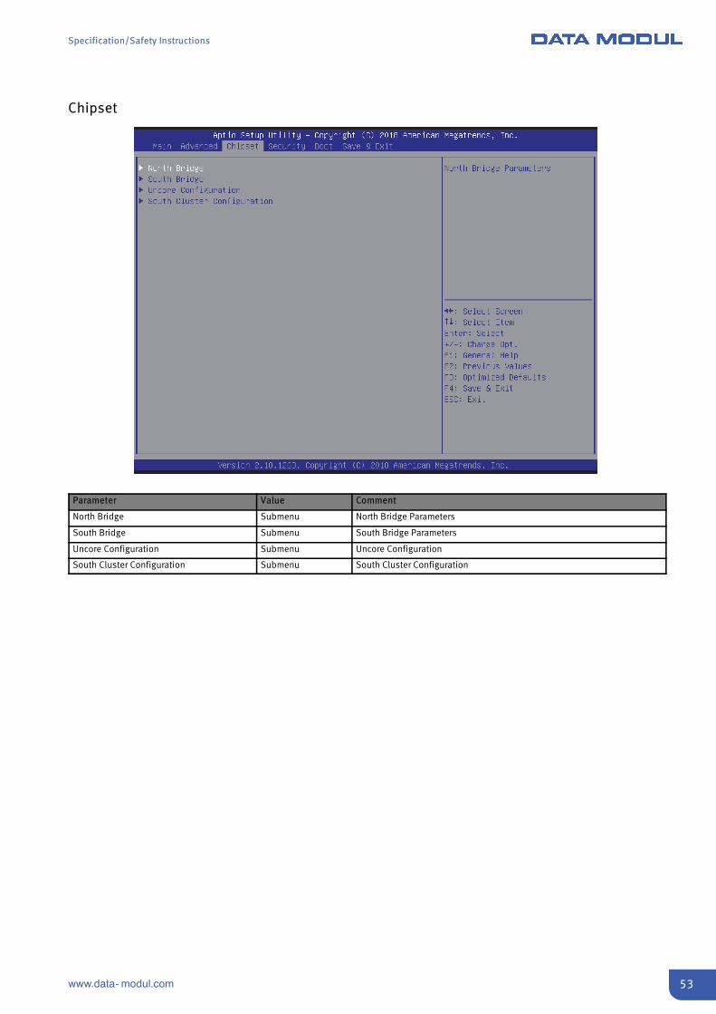
Chipset
Parameter Value Comment
North Bridge Submenu North Bridge Parameters
South Bridge Submenu South Bridge Parameters
Uncore Configuration Submenu Uncore Configuration
South Cluster Configuration Submenu South Cluster Configuration

Specification/Safety Instructions
54 www.data- modul.com
North Bridge
Parameter Value Comment
Max TOLUD 2 GB2.25 GB2.5 GB2.75 GB3 GB
Maximum Value of TOLUD. (Top of Low Usable DRAM).
Above 4GB MMIO BIOS assignment EnabledDisabled
Enable/Disable above 4GB MemoryMappedIO BIOS assignment.This is enabled automatically when Aperture Size is set to 2048MB.
PCIE VGA Workaround EnabledDisabled
Enable it if your PCIe card cannot boot to DOS.

Specification/Safety Instructions
55www.data- modul.com
South Bridge
Parameter Value Comment
Serial IRQ Mode QuietContinuous
Configure Serial IRQ Mode.
SMBus Support EnabledDisabled
Enable/Disable SMBus Support.
OS Selection WindowsAndroidWin7Intel Linux
Select the target OS.

Specification/Safety Instructions
56 www.data- modul.com
Uncore Configuration
Parameter Value Comment
Integrated Graphics Device EnabledDisabled
Enable: Enable Integrated Graphics Device (IGD) when selected as thePrimary Video Adaptor.Disable: Always disable IGD.
Primary Display IGDPCIeHG
Select which of IGD/PCIe Graphics device should be Primary Display.
RC6 (Render Standby) EnabledDisabled
Enable/Disable render standby support.
Aperture Size 128MB256MB512MB
Select the Aperture Size.
DVMT Pre-Allocated 64MB … 512MB64MB (default)
Select DVMT 5.0 Pre-Allocated (Fixed) Graphics Memory size used by theInternal Graphics Device.
DVMT Total Gfx Mem 128MB256MBMAX
Select DVMT5.0 Total Graphic Memory size used by the Internal GraphicsDevice.

Specification/Safety Instructions
57www.data- modul.com
South Cluster Configuration
Parameter Value Comment
PCI Express Configuration Submenu PCI Express Configuration settings
SATA Drives Submenu SATA Device Configuration
SCC Configuration Submenu SCC Configuration settings
USB Configuration Submenu USB Configuration settings
Miscellaneous Configuration Submenu Enable/Disable Misc. Features
Specification/Safety Instructions
58 www.data- modul.com
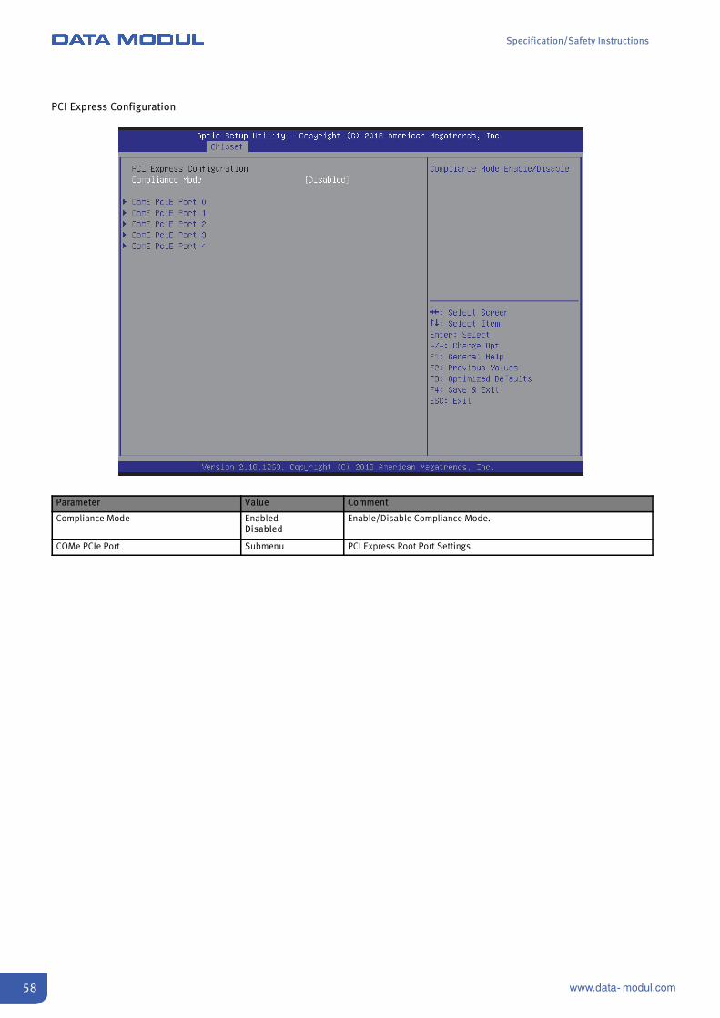
PCI Express Configuration
Parameter Value Comment
Compliance Mode EnabledDisabled
Enable/Disable Compliance Mode.
COMe PCIe Port Submenu PCI Express Root Port Settings.
Specification/Safety Instructions
59www.data- modul.com
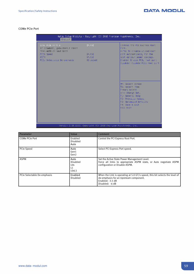
COMe PCIe Port
Parameter Value Comment
COMe PCIe Port EnabledDisabledAuto
Control the PCI Express Root Port.
PCIe Speed AutoGen1Gen2
Select PCI Express Port speed.
ASPM AutoDisabledL0sL1L0sL1
Set the Active State Power Management Level:Force all links to appropriate ASPM state, or Auto negotiate ASPMconfiguration or Disable ASPM.
PCIe Selectable De-emphasis EnabledDisabled
When the Link is operating at 5.0 GT/s speed, this bit selects the level ofde-emphasis for an Upstream component.Enabled: -3.5 dBDisabled: -6 dB

Specification/Safety Instructions
60 www.data- modul.com
SATA Configuration
Parameter Value Comment
SATA Controller EnabledDisabled
Enable/Disable the Chipset SATA Controller.
SATA Speed AutoGen1Gen2Gen3
Auto configures controller speed to max supported speed of connecteddevices.Other values limit speed to according value.
Aggressive LPM Support EnabledDisabled
Enable PCH to aggressively enter link power state.
Port EnabledDisabled
Enable/Disable SATA Port.
SATA Port Hot Plug Capability EnabledDisabled
If enabled, SATA port will be reported as Hot Plug capable.
Spin Up Device EnabledDisabled
If enabled for any of ports Staggered Spin Up will be performed and only thedrives which hav this option enabled will spin up at boot.Otherwise all drives spin up at boot.
SATA Device Type Hard Disk DriveSolid State Drive
Identify the SATA port is connected to Solid State Drive or Hard Disk Drive.
Specification/Safety Instructions
61www.data- modul.com
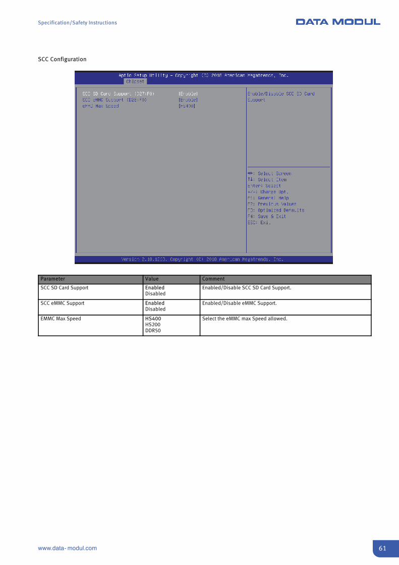
SCC Configuration
Parameter Value Comment
SCC SD Card Support EnabledDisabled
Enabled/Disable SCC SD Card Support.
SCC eMMC Support EnabledDisabled
Enabled/Disable eMMC Support.
EMMC Max Speed HS400HS200DDR50
Select the eMMC max Speed allowed.
Specification/Safety Instructions
62 www.data- modul.com
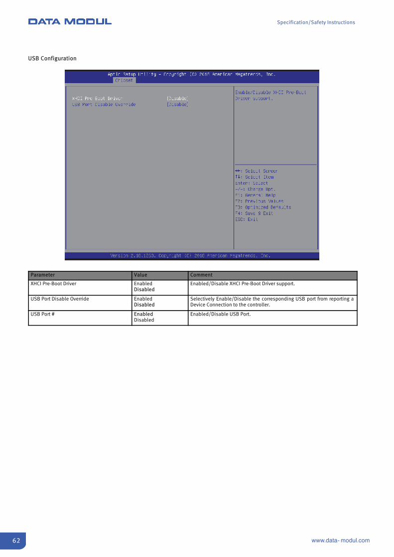
USB Configuration
Parameter Value Comment
XHCI Pre-Boot Driver EnabledDisabled
Enabled/Disable XHCI Pre-Boot Driver support.
USB Port Disable Override EnabledDisabled
Selectively Enable/Disable the corresponding USB port from reporting aDevice Connection to the controller.
USB Port # EnabledDisabled
Enabled/Disable USB Port.

Specification/Safety Instructions
63www.data- modul.com
Miscellaneous Configuration
Parameter Value Comment
Restore AC Power Loss S0 StateS5 StateLast State
Select AC power state when power is re-applied after a power failure.Power Off and Last State need a RTC battery in the system.
Board Clock Spread Spectrum EnabledDisabled
Enable Clock Chip’s Spread Spectrum feature.
Onboard LAN EnabledDisabled
Enable/Disable onboard GBe LAN Controller.
Wake On Lan EnabledDisabled
Enable/Disable the Wake On Lan.
Specification/Safety Instructions
64 www.data- modul.com
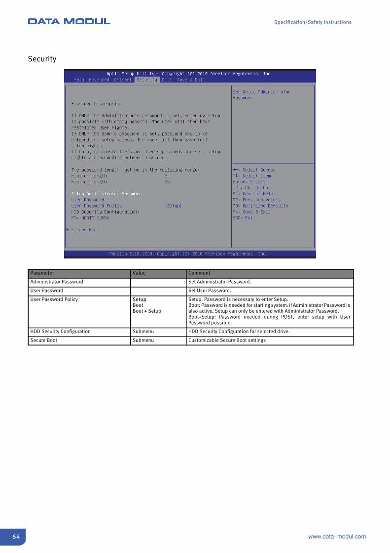
Security
Parameter Value Comment
Administrator Password Set Administrator Password.
User Password Set User Password.
User Password Policy SetupBootBoot + Setup
Setup: Password is necessary to enter Setup.Boot: Password is needed for starting system. If Administrator Password isalso active, Setup can only be entered with Administrator Password.Boot+Setup: Password needed during POST, enter setup with UserPassword possible.
HDD Security Configuration Submenu HDD Security Configuration for selected drive.
Secure Boot Submenu Customizable Secure Boot settings
Specification/Safety Instructions
65www.data- modul.com
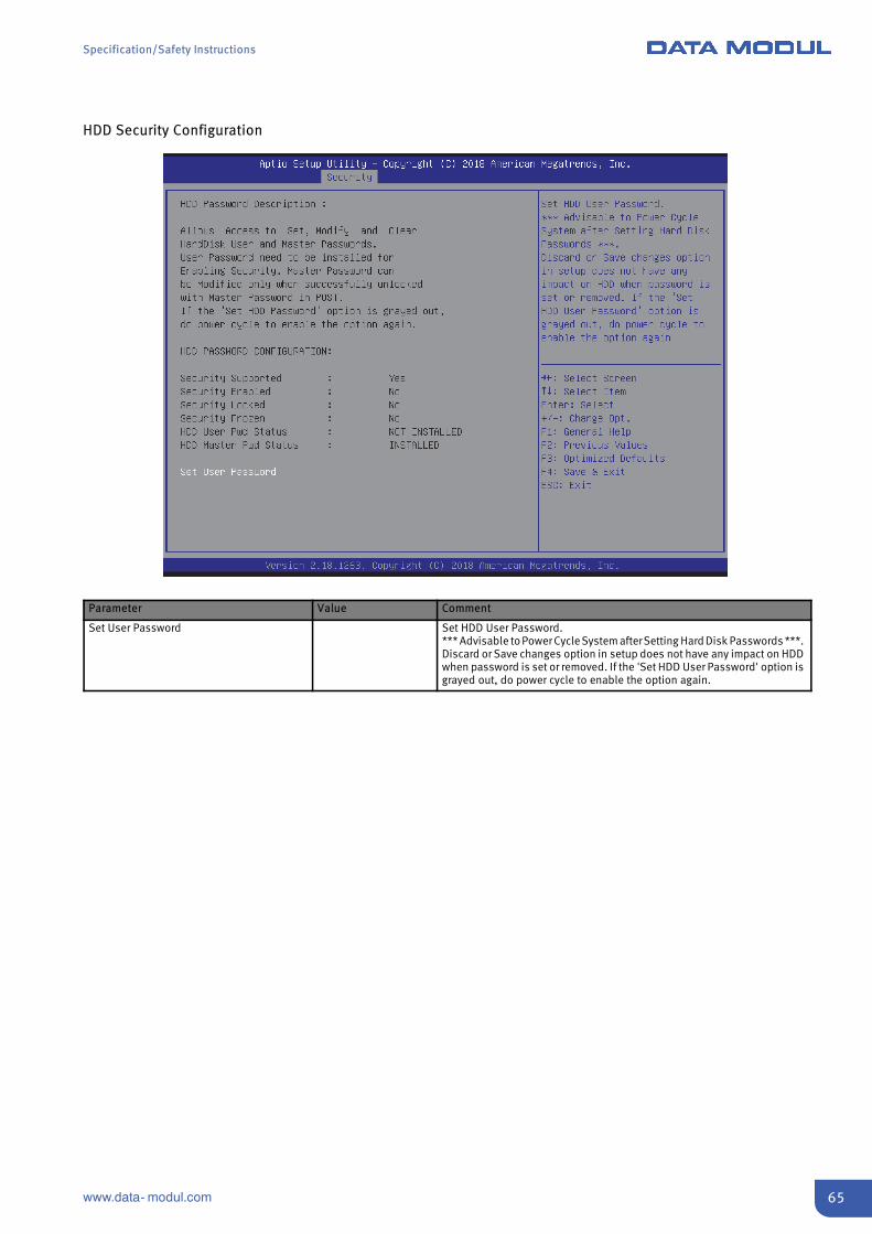
HDD Security Configuration
Parameter Value Comment
Set User Password Set HDD User Password.*** Advisable to Power Cycle System afterSetting Hard Disk Passwords ***.Discard or Save changes option in setup does not have any impact on HDDwhen password is set or removed. If the 'Set HDD User Password' option isgrayed out, do power cycle to enable the option again.
Specification/Safety Instructions
66 www.data- modul.com
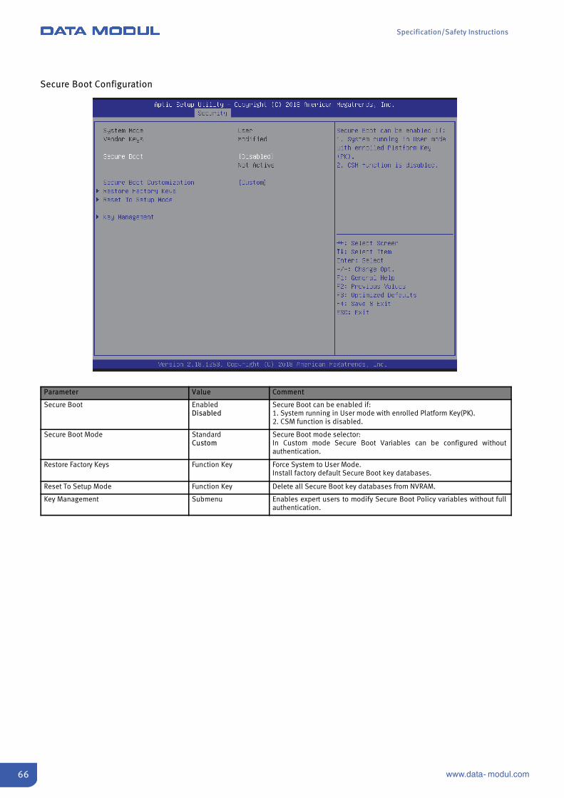
Secure Boot Configuration
Parameter Value Comment
Secure Boot EnabledDisabled
Secure Boot can be enabled if:1. System running in User mode with enrolled Platform Key(PK).2. CSM function is disabled.
Secure Boot Mode StandardCustom
Secure Boot mode selector:In Custom mode Secure Boot Variables can be configured withoutauthentication.
Restore Factory Keys Function Key Force System to User Mode.Install factory default Secure Boot key databases.
Reset To Setup Mode Function Key Delete all Secure Boot key databases from NVRAM.
Key Management Submenu Enables expert users to modify Secure Boot Policy variables without fullauthentication.
Specification/Safety Instructions
67www.data- modul.com
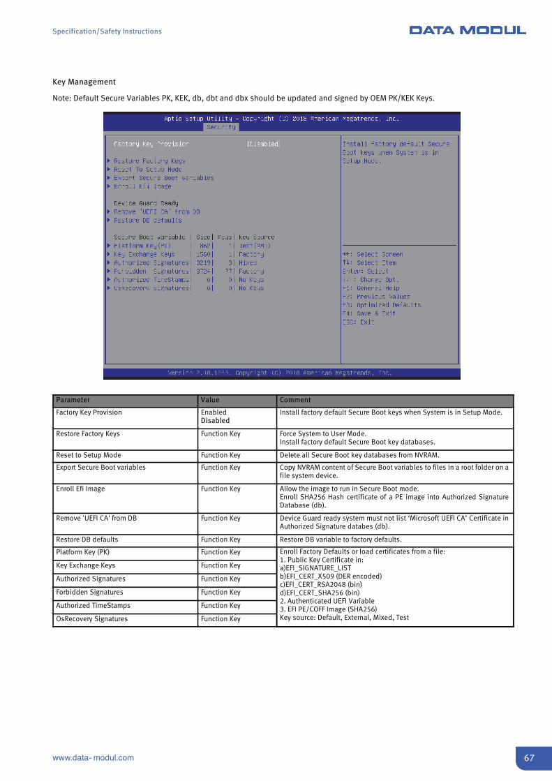
Key Management
Note: Default Secure Variables PK, KEK, db, dbt and dbx should be updated and signed by OEM PK/KEK Keys.
Parameter Value Comment
Factory Key Provision EnabledDisabled
Install factory default Secure Boot keys when System is in Setup Mode.
Restore Factory Keys Function Key Force System to User Mode.Install factory default Secure Boot key databases.
Reset to Setup Mode Function Key Delete all Secure Boot key databases from NVRAM.
Export Secure Boot variables Function Key Copy NVRAM content of Secure Boot variables to files in a root folder on afile system device.
Enroll Efi Image Function Key Allow the image to run in Secure Boot mode.Enroll SHA256 Hash certificate of a PE image into Authorized SignatureDatabase (db).
Remove 'UEFI CA' from DB Function Key Device Guard ready system must not list ‘Microsoft UEFI CA’ Certificate inAuthorized Signature databes (db).
Restore DB defaults Function Key Restore DB variable to factory defaults.
Platform Key (PK) Function Key Enroll Factory Defaults or load certificates from a file:1. Public Key Certificate in:a)EFI_SIGNATURE_LISTb)EFI_CERT_X509 (DER encoded)c)EFI_CERT_RSA2048 (bin)d)EFI_CERT_SHA256 (bin)2. Authenticated UEFI Variable3. EFI PE/COFF Image (SHA256)Key source: Default, External, Mixed, Test
Key Exchange Keys Function Key
Authorized Signatures Function Key
Forbidden Signatures Function Key
Authorized TimeStamps Function Key
OsRecovery Signatures Function Key
Specification/Safety Instructions
68 www.data- modul.com
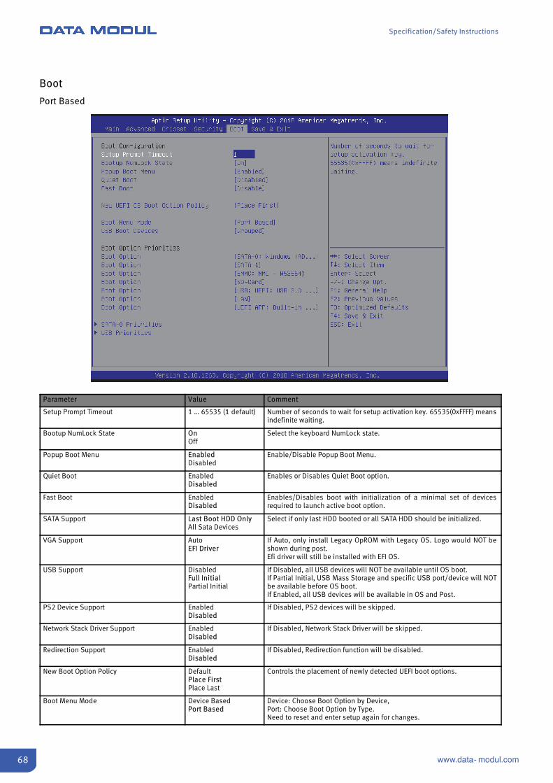
Boot
Port Based
Parameter Value Comment
Setup Prompt Timeout 1 … 65535 (1 default) Number of seconds to wait for setup activation key. 65535(0xFFFF) meansindefinite waiting.
Bootup NumLock State OnOff
Select the keyboard NumLock state.
Popup Boot Menu EnabledDisabled
Enable/Disable Popup Boot Menu.
Quiet Boot EnabledDisabled
Enables or Disables Quiet Boot option.
Fast Boot EnabledDisabled
Enables/Disables boot with initialization of a minimal set of devicesrequired to launch active boot option.
SATA Support Last Boot HDD OnlyAll Sata Devices
Select if only last HDD booted or all SATA HDD should be initialized.
VGA Support AutoEFI Driver
If Auto, only install Legacy OpROM with Legacy OS. Logo would NOT beshown during post.Efi driver will still be installed with EFI OS.
USB Support DisabledFull InitialPartial Initial
If Disabled, all USB devices will NOT be available until OS boot.If Partial Initial, USB Mass Storage and specific USB port/device will NOTbe available before OS boot.If Enabled, all USB devices will be available in OS and Post.
PS2 Device Support EnabledDisabled
If Disabled, PS2 devices will be skipped.
Network Stack Driver Support EnabledDisabled
If Disabled, Network Stack Driver will be skipped.
Redirection Support EnabledDisabled
If Disabled, Redirection function will be disabled.
New Boot Option Policy DefaultPlace FirstPlace Last
Controls the placement of newly detected UEFI boot options.
Boot Menu Mode Device BasedPort Based
Device: Choose Boot Option by Device,Port: Choose Boot Option by Type.Need to reset and enter setup again for changes.

Specification/Safety Instructions
69www.data- modul.com
Parameter Value Comment
USB Boot Devices GroupedBy Port
Show all USB Boot Devices in one group or show all USB Ports.
Boot Option Priorities Depends onrecognized device
Sets the boot order.Priority of devices from same type can be selected in BBS priority menus.
SATA Priorities Submenu Set the order of the devices in this group.Appears if more than 1 device of this group is connected.
USB Priorities Submenu Set the order of the devices in this group.Appears if more than 1 device of this group is connected.

Specification/Safety Instructions
70 www.data- modul.com
Device Based
Parameter Value Comment
Boot Option Priorities Depends onrecognized device
Sets the boot order.Priority of devices from same type can be selected in Priority Submenus.
Hard Drive BBS Priorities Submenu Set the order of the legacy devices in this group.Appears if more than 1 legacy device of this group is connected.
USB Device BBS Priorities Submenu Set the order of the legacy devices in this group.Appears if more than 1 legacy device of this group is connected.
Specification/Safety Instructions
71www.data- modul.com
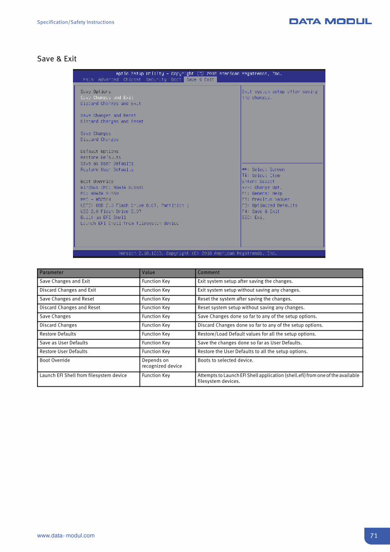
Save & Exit
Parameter Value Comment
Save Changes and Exit Function Key Exit system setup after saving the changes.
Discard Changes and Exit Function Key Exit system setup without saving any changes.
Save Changes and Reset Function Key Reset the system after saving the changes.
Discard Changes and Reset Function Key Reset system setup without saving any changes.
Save Changes Function Key Save Changes done so far to any of the setup options.
Discard Changes Function Key Discard Changes done so far to any of the setup options.
Restore Defaults Function Key Restore/Load Default values for all the setup options.
Save as User Defaults Function Key Save the changes done so far as User Defaults.
Restore User Defaults Function Key Restore the User Defaults to all the setup options.
Boot Override Depends onrecognized device
Boots to selected device.
Launch EFI Shell from filesystem device Function Key Attempts to LaunchEFI Shell application (shell.efi) from one of the availablefilesystem devices.

Specification/Safety Instructions
72 www.data- modul.com
This page intentionally left blank.

Specification/Safety Instructions
73www.data- modul.com
This page intentionally left blank.

Headquarters:
DATA MODUL AG Landsberger Str. 322 DE-80687 Munich - Germany Phone: +49-89-56017-0 Fax: +49-89-56017-119 www.data-modul.com
Logistics, Production & Services:
DATA MODUL Weikersheim GmbH Lindenstrasse 8 DE-97990 Weikersheim - Germany Phone: +49-7934-101-0 Fax: +49-7934-101-101
Subsidiaries & Sales Offices:
Germany – HamburgGermany – DuesseldorfDenmarkDubaiFinland/BalticFranceItalySingaporeSpainSwitzerlandUKUSA
DATA MODUL’s worldwide offices can be found on our website:www.data-modul.com/eu/sm/contact-us/offices.html
10
.20
13
DIN-EN-ISO 9001/14001 | www.data-modul.com