edward valves - flowserve · 3 flow control division edward valves table of contents (continued)...
TRANSCRIPT
Edward ValvesMaintenance Manual for
Edward Pressure-Seal ValvesV-377 R4
2
Flow Control Division
Edward Valves
Key to Illustrations ...........................................3Pressure-Seal Valve Figure Numbers ..................3Introduction ....................................................3Description of Pressure-Seal Valve Bonnet Types(Illustration, description and figure numbers)
Type I .........................................................4Type II ........................................................5Type III........................................................6Type IV .......................................................7
Service ProblemsPacking Chamber Leak .................................8Packing Recommendations ............................8Pressure-Seal Gasket Leaks..........................10Pressure-Seal Leak ......................................10Seat and Disk Joint Leaks ............................10Body Wall Leaks ........................................12Objectionable Vibration, Noise or Excessive Pressure Drop..............................12Valve Lubrication........................................12
Repair ProceduresValve Body Repairs ....................................13
Body Bore Gasket Seal Area Repair .........13Body Bore Guide Rib Repair ...................13Seat and Disk Repair ..............................14Body Wall Repair ...................................15
Valve Component Repair ............................15Disk-Piston Assembly Repair .....................15Bonnet or Cover Repair...........................16
Welding Rod Recommendations...................16Field Repair Equipment ...............................17
Disassembly Procedures forPressure-Seal Valves
Introduction ...............................................18First Determine the Area of Failure ...............18
Disassembly Procedures for Impactor Handles and Handwheels
Non-Ball Bearing Impactor Handles and Handwheels........................20Ball Bearing Impactor Handwheels ...........21
Procedures for Removing LimitorqueOperators from Valve Yokes
Revolving Stem Valves or Non-Revolving Stem Valves with Torque-Only Units...........22Non-Revolving Stem Valves with Torque and Thrust Units ...........................23
Procedures for Setting Actuator Torqueand Limit Switches
Limitorque Limit Switch and Torque Switch Setting Procedures .............24
Geared Limit Switch ............................24Torque Switch .....................................25Single Torque Switch ...........................25Double Torque Switch ..........................25Torque Switch Setting...........................26
Disassembly Procedures for Yoke AssembliesRevolving Stem Valves with Type I Bonnets .................................27Revolving Stem Valves with Type II Bonnets ................................28Non-Revolving Stem Valves with Type II or III Bonnets.........................28Valves with Type IV Bonnets .....................28
Procedures for Removing Operator and Yoke Assembly as a Unit
Revolving Stem Valves with Type I Bonnets .................................29Revolving Stem Valves with Type II Bonnets ................................29Non-Revolving Stem Valves with Type II, III or IV Bonnets....................30
Disassembly Procedures for Bonnet TypesType I Pressure-Seal Bonnets
– Stop and Stop-Check (Non-Return) Valves ..............................31
– Piston-Lift Check Valves .........................32Type II Pressure-Seal Bonnets
– Stop and Stop-Check (Non-Return) Valves with Revolving Stems ..................33
– Stop and Stop-Check (Non-Return) Valves with Non-Revolving Stems ...........34
Type III Pressure-Seal Bonnets– Stop and Stop-Check
(Non-Return) Valves ..............................36– Piston- Lift Check Valves ........................37– Tilting Disk Check Valves ......................38
Type IV Pressure-Seal Bonnets– Stop and Stop-Check
(Non-Return) Valves ..............................39– Piston-Lift Check Valves .........................41
Assembly of Composite Pressure- Seal Gaskets .................................................42Reassembly Procedures for Metal Pressure-Seal ValvesIntroduction...................................................43
Type I Pressure-Seal Bonnets– Stop and Stop-Check
(Non-Return) Valves ..............................44– Piston-Lift Check Valves .........................45
Type II Pressure-Seal Bonnets– Stop and Stop-Check (Non-Return)
Valves with Revolving Stems ..................45– Stop and Stop-Check (Non-Return)
Valves with Non-Revolving Stems ...........45Type III Pressure-Seal Bonnets
– Stop and Stop-Check (Non-Return) Valves ..............................46
– Piston-Lift Check Valves .........................46– Tilting Disk Check Valves ......................47
Type IV Pressure-Seal Bonnets– Stop and Stop-Check
(Non-Return) Valves ..............................47– Piston-Lift Check Valves .........................47
General Information.......................................48Supplementary Repair Information.......back coverOrdering Parts...................................back cover
Table of Contents

3
Flow Control Division
Edward ValvesTable of Contents (continued)
Illus No. Title PageI Pressure-Seal Bonnet Type I......................4
2 Pressure-Seal Bonnet Type II .....................53 Pressure-Seal Bonnet Type III ....................64 Pressure-Seal Bonnet Type IV....................75 Typical Globe Valve Nomenclature.........116 Pressure-Seal Bonnet Seal Angle.............167 Portable Lapping Tool for
Large Valves ........................................178 Van Norman Portable
Grinding Machine ................................179 Van Norman Portable
Boring Machine ...................................1710 Impactor Handwheel
Non-Ball Bearing Types .........................2011 Impactor Handwheel
Non-Ball Bearing Types .........................2012 Impactor Handwheel
Non-Ball Bearing Types .........................2013 Impactor Handwheel
Ball Bearing Type (with Impactogear)......2114 Torque-only Limitorque Operator on
Revolving Stem Valve (SMA or SMB) ......22
Illus No. Title Page15 Torque-only Limitorque Operator on
Revolving Stem Valve (SMB-4T or 5T)......2216 Torque-only Limitorque Operator on
Non-Revolving Stem Valve .....................2217 Torque and Thrust Limitorque Operator
on Non-Revolving Stem Valve ................2318 Limitorque Geared Limit Switch Assy.......2419 Single & Double Torque
Switch Assemblies ................................2520 Type I Bonnet on Stop-Check Valve.........2721 Type I Bonnet on Piston-Lift Check Valve ..2922 Type II Bonnet on Revolving
Stem Stop Valve ...................................3023 Type II Bonnet on Non-Revolving
Stem Stop Valve ...................................3124 Type III Bonnet on Stop Valve.................3425 Type III Bonnet on Piston-Lift
Check Valve ........................................3526 Type III Bonnet on Tilting
Disk Check Valve..................................3827 Type IV Bonnet on Stop-Check Valve.......3928 Type IV Bonnet on Piston-Lift
Check Valve ........................................41
Key to Illustrations IntroductionThis manual has been prepared toserve as a guide for the maintenanceof Edward valves of the pressure-sealbonnet joint construction. It isdesigned to help you obtain the mostsatisfactory service from these valves.Although rigid metallurgical, radi-ographic, physical, and visual inspec-tion is the standard procedure for allEdward products, it is inevitable thatsome valves, after a period of time,may occasionally require repair.When this happens, this manual willassist you so that your valve may besatisfactorily restored to good work-ing condition with a minimum of timeand expense.
ScopeBefore starting, it will be helpful tohave some understanding of thevalve’s physical construction. Con-sequently, the four basic types of pressure-seal constructions are dis-cussed and illustrated first. All Edwardpressure-seal valves employ one ofthese four basic types, or a minormodification thereof. Non-pressure-seal, or bolted bonnet type valves, are not included in this manual.The next major section of this manualdiscusses the more common serviceproblems and failures. It identifies theproblem and explains the reasons forcertain failures. The reason should be understood before work is actually started.
602Y606606Y607607Y614Y616616Y617
617Y692Y694694Y695695Y702Y714Y792Y
970Y1570Y1602Y1614Y1692Y1802Y1814Y1892Y2002Y
2006Y2007Y2014Y2016Y2017Y2070Y2092Y2094Y2095Y
2570Y3902Y39063906Y39073907Y3914Y39163916Y
39173917Y3948Y3992Y39943994Y39953995Y4002Y
40064006Y40074007Y4014Y40164016Y40174017Y
4092Y40944094Y40954095Y4302Y4306Y4307Y4314Y
4316Y4317Y4370Y4392Y4394Y4395Y4402Y4406Y4407Y
4414Y4416Y4417Y4448Y4470Y4492Y4494Y4495Y4502Y
4514Y4570Y4592Y7502Y75067506Y75077507Y7514Y
75167516Y75177517Y7548Y7592Y75947594Y75957595Y
Pressure-seal Valve Figure Numbers

4
Flow Control Division
Edward Valves
The procedure to be followed in makingthe repair is then explained. This includesnormal valve maintenance as well as majorvalve repair. Field repair equipment, avail-able from Edward, is described andillustrated. Valve lubrication and weldingrod recommendations are also made.These procedures are adequate for almostany pressure-seal valve repair or mainte-nance problem that may arise in the field.Following is the section describing thedisassembly procedure for the variousvalve components; for example, manual ofLimitorque operators, valve yokes, and thefour basic bonnet types. It is very impor-tant that the Introduction and the para-graphs titled “First Determine the Area ofFailure” be read and understood beforeany disassembly work is begun. Severalprocedures are described, depending uponthe area of failure. Considerable time canoften be saved by first selecting the properdisassembly procedure.The last major section explains how thevarious valve constructions are to bereassembled. Information on how tocontact Edward for additional advice, ifrequired, and how to order parts isincluded.
Description of Pressure-Seal Valve TypesEdward pressure-seal valves are built withfour basic bonnet arrangements to providethe most suitable designs for the widerange of sizes and pressure classesoffered.
Type I is the studded bonnet design asshown. It uses the basic pull-up constructionwith studs in the bonnet projecting throughthe retainer for tightening by use of nuts. Itis a simplified design employed in moder-ate pressure applications and certain valvesizes, as shown in the following table.
Description of Pressure-Seal Bonnet Types – Type IType I
Illustration No. 1 Pressure-Seal Bonnet
Fig. No. Pressure Rating Type of Valve Size602Y 600 Flite-Flow Globe Stop-Check (Y-Type) 6-20606 and 606Y 600 Globe Stop-Check 8-14607 and 607Y 600 Angle Stop-Check 8-14614Y 600 Flite-Flow Globe Stop (Y-Type) 6-20616 and 616Y 600 Globe Stop 8-14617 and 617Y 600 Angle Stop 8-14692Y 600 Flite-Flow Check (Y-Type) 16-20694 and 694Y 600 Horizontal Check 8-14695 and 695Y 600 Angle Check 8-14702Y 600-SPL Flite-Flow Globe Stop-Check (Y-Type) 16-20714Y 600-SPL Flite-Flow Globe Stop (Y-Type) 6-20792Y 600-SPL Flite-Flow Check (Y-Type) 16-201602Y Special Flite-Flow Globe Stop-Check (Y-Type) 16-201614Y Special Flite-Flow Check Stop (Y-Type) 16-201692Y Special Flite-Flow Check (Y-Type) 16-201802Y Special Flite-Flow Globe Stop-Check (Y-Type) 16-201814Y Special Flite-Flow Globe Stop (Y-Type) 16-201892Y Special Flite-Flow Check (Y-Type) 16-20
Type I

5
Flow Control Division
Edward ValvesDescription of Pressure-Seal Bonnet Types – Type II
Type II
Illustration No. 2Pressure-Seal Bonnet
Fig. No. Pressure Rating Type of Valve Size
2002Y 1500-SPL Flite-Flow Globe Stop-Check (Y-Type) 3 – 42006Y 1500-SPL Globe Stop-Check 2-1/2 – 42007Y 1500-SPL Angle Stop-Check 2-1/2 – 42014Y 1500-SPL Flite-Flow Globe Stop (Y-Type) 3 – 42016Y 1500-SPL Globe Stop 2-1/2 – 42017Y 1500-SPL Angle Stop 2-1/2 – 43902Y 2500 Flite-Flow Globe Stop-Check (Y-Type) 3-243906 and 3906Y 2500 Globe Stop-Check 2-1/2 – 123907 and 3907Y 2500 Angle Stop-Check 2-1/2 – 223914Y 2500 Flite-Flow Globe Stop (Y-Type) 3-243916 and 3916Y 2500 Globe Stop-Check 2-1/2 – 123917 and 3917Y 2500 Angle Stop-Check 2-1/2 – 223948Y 2500 Elbow Down Stop-Check 10-164002Y 900 Flite-Flow Globe Stop (Y-Type) 3 – 44006 and 4006Y 900 Globe Stop-Check 2-1/2 – 44007 and 4007Y 900 Angle Stop-Check 2-1/2 – 44014Y 900 Flite-Flow Globe Stop (Y-Type) 3 – 44016 and 4016Y 900 Globe Stop 2-1/2 – 44017 and 4017Y 900 Angle Stop 2-1/2 – 44302Y 900-SPL Flite-Flow Globe Stop-Check (Y-Type) 3 – 44306Y 900-SPL Globe Stop-Check 2-1/2 – 44307Y 900-SPL Angle Stop-Check 2-1/2 – 44314Y 900-SPL Flite-Flow Globe Stop (Y-Type) 3 – 44316Y 900-SPL Globe Stop 2-1/2 – 44317Y 900-SPL Angle Stop 2-1/2 – 44402Y 2500-SPL Flite-Flow Globe Stop-Check (Y-Type) 3-244406Y 2500-SPL Globe Stop-Check 2-1/2 – 124407Y 2500-SPL Angle Stop-Check 2-1/2 – 224414Y 2500-SPL Flite-Flow Globe Stop (Y-Type) 3-244416Y 2500-SPL Globe Stop 2-1/2 – 124417Y 2500-SPL Angle Stop 2-1/2 – 224448Y 2500-SPL Elbow Down Stop-Check 10-164502Y 4500 Flite-Flow Globe Stop-Check (Y-Type) 8-104514Y 4500 Flite-Flow Stop (Y-Type) 8-104592Y 4500 Flite-Flow Check (Y-Type) 8-107502Y 1500 Flite-Flow Globe Stop-Check (Y-Type) 3 – 47506 and 7506Y 1500 Globe Stop-Check 2-1/2 – 47507 and 7507Y 1500 Angle Stop-Check 2-1/2 – 47514Y 1500 Flite-Flow Globe Stop (Y-Type) 3 – 47516 and 7516Y 1500 Globe Stop 2-1/2 – 47517 and 7517Y 1500 Angle Stop 2-1/2 – 4
Type II Type II is the push-up design in which thebonnet retainer ring is screwed onto thebonnet, and cap screws develop theupward force. This design is employed onboth intermediate and high-pressure appli-cations. A three-piece construction is usedfor the pressure-seal parts.

6
Flow Control Division
Edward Valves
Type III also uses the three-piece pressure-seal construction but combines it with thebasic pull-up bonnet. This design is utilizedextensively in the larger valves.
Description of Pressure-Seal Bonnet Types – Type III
Type III
Illustration No. 3Pressure-Seal Bonnet
Fig. No. Pressure Rating Type of Valve Size
602Y 600 Flite-Flow Stop-Check (Y-Type) 24-32607Y 600 Angle Stop-Check 24-30614Y 600 Flite-Flow Globe Stop (Y-Type) 24-32617Y 600 Angle Stop 24-30692Y 600 Flite-Flow Check (Y-Type) 24-32695Y 600 Angle Check 24-30702Y 600-SPL Flite-Flow Globe Stop-Check (Y-Type) 24-32714Y 600-SPL Flite-Flow Globe Stop (Y-Type) 24-32792Y 600-SPL Flite-Flow Check (Y-Type) 24-32970Y 900 Tilting Disk Check 2-1/2 – 241570Y 1500 Tilting Disk Check 3-241602Y Special Flite-Flow Globe Stop-Check (Y-Type) 24-321614Y Special Flite-Flow Globe Stop (Y-Type) 24-321692Y Special Flite-Flow Check (Y-Type) 24-321802Y Special Flite-Flow Globe Stop-Check (Y-Type) 24-321814Y Special Flite-Flow Globe Stop (Y-Type) 24-321892Y Special Flite-Flow Check (Y-Type) 24-322002Y 1500-SPL Flite-Flow Globe Stop-Check (Y-Type) 6-182006Y 1500-SPL Globe Stop-Check 5-142007Y 1500-SPL Angle Stop-Check 5-242014Y 1500-SPL Flite-Flow Globe 6-182016Y 1500-SPL Globe Stop 5-142017Y 1500-SPL Angle Stop 5-242070Y 1500-SPL Tilting Disk Check 3-242092Y 1500-SPL Flite-Flow Check (Y-Type) 3-182094Y 1500-SPL Horizontal Check 2-1/2 – 142095Y 1500-SPL Angle Check 2-1/2 – 242570Y 2500 Tilting Disk Check 3-243992Y 2500 Flite-Flow Check (Y-Type) 3-243994 and 3994Y 2500 Horizontal Check 2-1/2 – 123995 and 3995Y 2500 Angle Check 2-1/2 – 244006 and 4006Y 900 Globe Stop-Check 5-144007 and 4007Y 900 Angle Stop-Check 5-244014Y 900 Flite-Flow Stop (Y-Type) 6-164016 and 4016Y 900 Globe Stop 5-14
Type III

7
Flow Control Division
Edward Valves
Description of Pressure-Seal Bonnet Types – Type III and Type IV
Fig. No. Pressure Rating Type of Valve Size
4017 and 4017Y 900 Angle Stop 5-244092Y 900 Flite-Flow Check (Y-Type) 3-164094 and 4094Y 900 Horizontal Check 2-1/2 – 144095 and 4095Y 900 Angle Check 2-1/2 – 244302Y 900-SPL Flite-Flow Globe Stop-Check (Y-Type) 5-164306Y 900-SPL Globe Stop-Check 5-144307Y 900-SPL Angle Stop-Check 5-244316Y 900-SPL Globe Stop 5-144317Y 900-SPL Angle Stop 5-244392Y 900-SPL Flite-Flow Check (Y-Type) 3-164370Y 900-SPL Tilting Disk Check 2-1/2 – 204394Y 900-SPL Horizontal Check 2-1/2 – 144395Y 900-SPL Angle Check 2-1/2 – 244470Y 2500-SPL Tilting Disk Check 3-244492Y 2500-SPL Flite-Flow Check (Y-Type) 3-244494Y 2500-SPL Horizontal Check 2-1/2 – 124495Y 2500-SPL Angle Check 2-1/2 – 244570Y 4500 Tilting Disk Check 6-107502Y 1500 Flite-Flow Globe Stop-Check (Y-Type) 6-187506 and 7506Y 1500 Globe Stop-Check 5-147507 and 7507Y 1500 Angle Stop-Check 5-247514Y 1500 Flite-Flow Globe Stop (Y-Type) 6-187516 and 7516Y 1500 Globe Stop 5-147517 and 7517Y 1500 Angle Stop 5-247548Y Special Elbow Down Stop-Check 10-187592Y 1500 Flite-Flow Check (Y-Type) 3-187594 and 7594Y 1500 Horizontal Check 2-1/2 – 147595 and 7595Y 1500 Angle Check 2-1/2 – 247598Y Special Elbow Down Check 10-18
Fig. No. Pressure Rating Type of Valve Size
4502Y 4500 Flite-Flow Globe Stop-Check (Y-Type) 4-64514Y 4500 Flite-Flow Globe Stop (Y-Type) 4-64592Y 4500 Flite-Flow Check (Y-Type) 4-6
Type IV design used in the 4500 lb. valveis unique in that the gasket retainer seg-ments are located below the bonnet. Thepressure-seal force is derived by pulling thebonnet retainer down.
Type IV
Illustration No. 4Pressure-Seal Bonnet
Type III (continued)
Type IV

8
Flow Control Division
Edward Valves
Packing Chamber LeakWhere moisture appears or actual drippingoccurs at the packing chamber around thestem, gland or gland flange, which cannotbe eliminated by retorqueing the gland bolt,the following points should be considered.
1. The packing may have become hard.Replace the packing.
2. Gland travel has been fully taken up.Repack with new packing.
3. The wrong packing is being used. See packing recommendations shownon this page.
4. A stem should be replaced when ithas become deeply scratched,burred, or otherwise mutilated fromcareless handling, or where the stemhas worn, tapered or has been bent.
5. The gaps in the rings of split packinghave not been staggered around thestem. They should be inserted in thismanner.
6. The packing gland may be bindingagainst the packing chamber or stemand does not compress the packingproperly. Make certain the gland fitsthe packing chamber and is tight-ened down equally on each side.
Packing RecommendationsEdward valves are packed with all-purposepacking sets.This is a combination of pack-ing using braided rings at the top and bot-tom of the packing chamber and flexiblegraphite packing in the center section.Packing glands should be tightened downenough to prevent leakage but not enoughto develop excessive operating torque.When the gland has advanced approxi-mately half way into the packing chamber,it is recommended that additional packingrings be added. To obtain best results, thestem should be thoroughly cleaned.Replacement packing should be the sameas that originally furnished.We recommend that replacement packingbe purchased from Edward Valves toassure packing with the proper density andcorrosion inhibitors are always used.
Important:Long service life from modern graphiticpacking requires that adequate preloadsbe applied when repacking.
1. All parts should be clean and notscored or pitted, especially the stem.
2. The valve internal parts and bonnetshould be assembled prior toinstalling the packing.
3. Position split packing rings with theends of adjacent rings rotated 90°.
4. Install in the following sequence:Bottom Ring – Braided RingCenter Rings – Die formed
expanded graphiteTop Ring – Braided Ring
5. Clean and lubricate the gland eye-bolts.
6. Carefully seat each individual pack-ing ring before adding the next ring.
7. Apply the recommended torque to thegland nuts evenly without cocking thegland. See Table A for recommendedtorques.
8. Tighten the nuts to the initial valuesshown, then loosen and retighten tothe final torque.
9. Stroke the valve, then recheck thegland nut torques.
NOTE: The torque values given are forsealing full-rated pressure. For line pres-sures less than the full CWP rating of thevalve, the final torques may be reduced bythe ratio of Pactual/CWP down to a mini-mum of Pactual = 1500 psig. This willreduce packing drag and extend packinglife.
Service Problems

9
Flow Control Division
Edward ValvesService Problems (continued)
Initial FinalFigure Numbers Size Torque Torque
2.5 27 83 27 8
604, 605, 606, 607 4 41 12616, 617, 618, 619 5 55 16704, 705, 706, 707 6 60 17716, 717, 718, 719 8 89 26
10 143 4112 209 6014 233 67
6 48 148 55 1610 62 18
602, 614, 702, 714 12 84 2414 84 2416 353 10220 571 165
Table AGland Bolt Torques, ft.-lbs.
Class 600 Valves
Initial FinalFigure Numbers Size Torque Torque
6 58 258 69 30
4002, 4014, 4302, 4314 10 115 5012 185 8014 185 8016 206 89
3 55 244 79 34
4006, 4007, 4016, 4017 5 84 364306, 4307, 4316, 4317 6 89 39
8 143 6210 199 8612 252 109
4006, 4016, 4306, 4316 14 266 115
14 252 1094007, 4017, 4307, 4317 16 331 143
20 633 274
Table A (continued)Gland Bolt Torques, ft.-lbs.
Class 900 Valves
Initial FinalFigure Numbers Size Torque Torque
7506, 7507, 7516, 7517 2.5 29 212006, 2007, 2016, 2017 3 55 40
4 78 575 84 61
7502, 7506, 7507, 7514 6 90 657516, 7517, 2002, 2006, 8 200 1452007, 2014, 2016, 2017 10 159 114
12 353 255
7502, 7514 14 353 255
7506, 7507, 7516, 7517 14 378 2732006, 2007, 2016, 2017
7502, 7507, 7514, 7517 16 672 4842002, 2007, 2014, 2017 18 672 484
Table A (continued)Gland Bolt Torques, ft.-lbs.
Class 1500 Valves
Initial FinalFigure Numbers Size Torque Torque
3906, 3507, 3916, 3917 2.5 29 294406, 4407, 4416, 4417 3 51 51
4 60 605 90 90
3902, 3906, 3907, 3914, 6 143 1433916, 3917, 4402, 4406, 8 267 2674407, 4414, 4416, 4417 10 286 286
12 473 4733902, 3907, 3914, 3917 14 479 4794402, 4407, 4414, 4417 16 479 479
19 269 26920 269 269
Table A (continued)Gland Bolt Torques, ft.-lbs.
Class 2500 Valves

10
Flow Control Division
Edward Valves
Pressure-Seal Gasket LeakEdward valves have been produced withtwo types of pressure-seal gasket: Earliervalves had metal gaskets, while laterdesigns have composite expanded graphitegaskets. The valves with composite gasketscan be identified by a “B” prefix on the fig-ure number. Assembly and disassembly ofthe two gasket types are essentially thesame except the composite gasket designsmay have belleville spring washers under
the nuts (or capscrews) of the pull-up bolt-ing, and the tightening torque requirementsfor the pull-up bolting are different.To guard against leakage, the bolts shouldbe kept tightened at all times.A torque wrench should be used for tighten-ing the bonnet or cover retainer stud nuts orcapscrews, which are used to preload thepressure-seal gasket.All nuts/capscrews should be tightened inan alternating star pattern to ensure eventightening.The bolting should be tightened to thetorque values shown in Table B while thevalve is under full line pressure.
Pressure-Seal LeakShould the leak fail to stop after tightening,it must be concluded that there is an imper-fect pressure-seal, and the valve will haveto be opened for examination. (Note:Regardless of the cause of failure, openedpressure-seal bonnets should always bereassembled with a new gasket. These areavailable from stock via Air Express fromRaleigh, North Carolina.) Such a leak mayresult from any of the following causes:
1. Incomplete Seal Between Bonnet andGasket. An incomplete seal aroundthe gasket seating surface of the bon-net (or cover on check valves) may becaused by corrosion, dirt, chips, orother foreign matter on the mating sur-faces of the sealing angle.
2. Incomplete Seal Between Body I.D.and Gasket. An incomplete seal inthe area of the gasket and body I.D.contact may be caused by surface
imperfections in the body wall in theform of pin holes, extended cracks, orindentations where the metal hasfailed sometime after valve installationand use. Such imperfections may besurface indications of deeper flaws inthe body casting that may cause a by-pass around the pressure-seal.
Seat and Disk Joint LeakA leak existing between the seat and diskof a closed valve might be indicated byone of the following: a definite pressureloss in the high-pressure side of the valve;continued flow through an inspection drainon the low-pressure side; or, in hot water orsteam lines, a downstream pipe thatremains hot beyond the usual length of timeand conductivity range.Such a leak may be the result of a distortedseat caused by uneven welding and stress-relieving temperatures that were present inthe body when mounting the valve in thepipe line. It may also develop because ofthe operator’s failure to close the valvetightly. An increased velocity is imparted toa flow forced through a very small open-ing. This increased velocity subsequentlygives rise to the “cutting” of both disk andseat, particularly by particles of line scaleor rust in suspension or normal solids insolution; or, in spite of the fact that the stel-lited hard-facing material on the seat anddisk is corrosion and erosion resistant,grooves, pit marks, or other surface irregu-larities may be formed on the seat and diskjoint surfaces when the disk is closedagainst a foreign body on the seat. Thissometimes occurs during the initial start-upof a piping system.
Service Problems (continued)
Table BBonnet/Cover Bolt/Nut Pull-Up
Torques (With Valve Under Pressure)
REQUIRED TORQUE, FT-LBSBOLT SIZE METAL COMPOSITE
GASKET GASKET3/8 18 5
7/16 30 51/2 45 7
9/16 68 105/8 90 153/4 150 257/8 240 351 370 55
1-1/8 533 801-1/4 750 1101-3/8 1020 1501-1/2 1200 1701-5/8 1650 2301-3/4 2250 3201-7/8 3000 420
2 3300 460

11
Flow Control Division
Edward Valves
Leakage of steam through a valve that isbadly steam-cut has a whistling orsonorous sound. If the valve is only slightlysteam-cut, however, leakage is identifiedby subdued gurgling or weak poppingsounds. These sounds can be heardthrough a stethoscope or by placing oneend of a stick against the valve body whileholding the other end between the teeth,with hands over the ears.To check for a properly closed valve, onvalves with nonrising type handwheels(non-revolving stem), an indicator isattached to the lower side of the yokebushing that coincides with a pointerattached to the yoke, when the valve istightly closed. This can be viewed throughone of the yoke windows and it representsthe same relative position between theyoke and yoke bushing, as when the valvewas hydrostatically seat-tested and foundto be tight at the factory. The hydrostaticpressure is stamped on the indicator. It isonly natural that the indicator will travelpast this mark after repeated closings.Some operators hesitate to force the valvecrossarm under the handwheel further thanthis button, but no harm will be done evenif the indicator travels more than an inchpast the mark when holding a desiredpressure. If a tight seal is not made afterrepeated impact blows, it must be conclud-ed that the pressure is bypassing either atthe seat joint or body diaphragm betweenthe inlet and the outlet passage. Inspectionof the interior of the valve now is advisable.
HANDWHEEL–IMPACTOR TYPE
BEARINGS–USED ON NON-REVOLVING STEM VALVES ONLY;TAPERED AND SPHERICAL ROLLERBEARINGS ALSO USED
LOCATION OF “INDICATOR” ONYOKE BUSHING TO INDICATEWHEN VALVE IS TIGHTLY SEATED
LOCATION OF “POINTER” ON YOKE TO INDICATE WHENVALVE IS TIGHTLY SEATED
ONE-PIECE PACKING GLAND (OR 2-PIECE GLAND FLANGEAND GLAND ASSEMBLY)
YOKE LOCK RING(2 PIECES)
BONNET BACKSEAT
COVER RETAINERSTUDS ORCAP SCREWS
COVER RETAINERUSED ONCHECK VALVES
PRESSURE-SEALCOVER, USED ONCHECK VALVES
YOKE BUSHING USED ON VALVESWITH NON-REVOLVING STEMS(CALLED STEM BUSHING ON LIMITORQUE OPERATED VALVES)
TYPICAL YOKE–USED ON VALVESWITH NON-REVOLVING STEMS(YOKES USED ON OTHER VALVETYPES DIFFER)
BONNET RETAINER
SPACER RINGPRESSURE-SEAL GASKETPACKING CHAMBER
STEM THREADS
STEM GUIDE COLLAR ON NON-REVOLVING STEMS
STEM
STEM BACKSEAT
DISK NUT
STEM COLLAR
DISK
LOCKWELD
BODY GUIDE RIBS(ONLY ONE SHOWN)
SEAT WITH STELLITEHARD FACING
FOR STOPCHECKVALVESDISK PISTONASSEMBLY
PISTONPISTON
FORCHECKVALVES DISK
BODY
FOR STOP VALVES
DISK STEMASSEMBLY
TYPICAL PRESSURE-SEAL BONNET AS USED ON STOP &STOP-CHECK VALVES
GASKET RETAINER SEGMENTS(SEVERAL PIECES)
}
Illustration No. 5Typical Globe Valve Nomenclature
Service Problems (continued)

12
Flow Control Division
Edward Valves
Body Wall LeakThis is a visual leak through the body wall,welding end or end flanges and may be theresult of a shrink cavity or other void in thecasting. If small at first, such a leak may gounnoticed for a time, particularly if the valveis heavily insulated and the pipe line at thatpoint is sufficiently warm to keep the insula-tion dry enough to escape notice.
Objectionable Vibration, Noise orExcessive Pressure DropExcessive vibration noise or humming com-ing from within a stop-check, non-return orcheck valve indicates the possibility thatthe disk-piston assembly is wedged insidethe body. Such sticking may be caused byuneven body guide rib wear on the down-stream side induced by oversizing thevalve, or by corrosion, by flakes of linescale, or by particles of weld spatter thatmay have entered the valve during con-struction of the piping, and which laterwashed up into the piston bearing area ofthe body I.D.On stop-check and non-return valves, thestem position is indicated by the stemguide collar on non-revolving stems, or bythe position of the handwheel on revolvingstems; the stem should normally be fullyopen against the bonnet backseat in orderthat the disk-piston can lift the full amount.When the disk is not touching the bottomof the stem or the bottom stop lugs on thebonnet (due to a wedged disk-piston orinsufficient flow, for example), then the diskassembly is free to move laterally withinthe body. This motion in most cases causesa slight vibration which can be felt throughthe body, yoke and handwheel.
Screwing the stem down slowly to contactthe disk first increases the intensity of vibra-tion to the hand and to the ear, but furtherdownward, movement of the stem buildssufficient contact pressure and eliminatesthe vibration. This also tends to dislodgeany foreign particles that may have beenthe initial cause for disk-piston wedging.The position of the lift indicator on theyoke, where vibration ceased, should benoted and any increase in pressure dropindicated on available gauges recorded. Itmay be that when the stem is screwedback to the full open position, the disk willagain remain in a floating position, whichcould indicate oversizing of the valve forthe flow conditions. It is always recom-mended that check valve size selection begoverned by flow conditions rather than byadjacent piping. Oversizing induces vibra-tion or noise and causes excessive, unevenguide rib wear, giving rise to greater disk-piston assembly clearance on one side ofthe body.By means of other valves in the line, it maybe possible to vary the rate of flow througha noisy check valve sharply enough (in ashort period of time) to dislodge the pistonfrom its wedged position.
Valve LubricationIn order to obtain full service life, valvesrequire periodic lubrication of the bearingsand stem threads, as does any rotatingmachinery.
On valves where the stem bushing andbearings are in the motor operator, thebearings are lubricated by the operatorlube supply, which should be maintained at the recommend level.Valves that have bearings in the top of theyoke have lube fittings on the valve yokefor convenient relubrication. Stem threads also require periodic replen-ishment of the lubricant. Exposed threadsshould be wiped clean of old grease andaccumulated dirt and fresh lubricantapplied. This can be most effectively donewith the valve in the closed position.For valves that see frequent operation, thelubricant should be replenished on bear-ings and stem threads every three months.If extreme service conditions dictate, theplant operating engineer should establish a more frequent relube schedule.For valves that are operated infrequently,relubrication at least once a year is recom-mended. The recommended lubrication forboth bearings and stem threads is Rykon EP#2, manufactured by The American OilCompany. This is an extreme-pressure,extreme-temperature lubricant of highquality.Valves equipped with automatic stem lubri-cators should be maintained in accordancewith the above instructions for the bearingsand as required to maintain the lube levelin the stem lubricator reservoir.
Service Problems (continued)

13
Flow Control Division
Edward Valves
VALVE BODY REPAIRS
Body Bore Gasket Seal Area Repairwith Metal Gasket OnlyPressure-seal valves made prior to 1952were made with a 47° bonnet seal angleand the body bore seal was in the parentmetal of the body castings. In 1952 thedesign was changed to a 25° seal angleand the body castings were inlayed with 18-8 stainless at the seal area. When a leakdeveloped on the older valves, the gasket aswell as the body bore were wire drawn.If the depth of defects are .010” or less,the seal area can be honed using aportable Sunnen Hone. This device isadjustable for different bore sizes and canbe operated by one man using a portableelectric drill of 1/2“ to 3/4“ capacity.When the defects are greater than .010”,welding will be required to cut down therepair time.First make visual inspection all around thisarea, noting, if possible, where flaws mayoccur. Next wash the area with a suitablesolvent, drying with clean rags and, if nec-essary, polishing with a fine grade ofemery cloth to remove any undesirablescale or foreign matter that may have beendeposited on the area suspected of havingflaws. Use a dye penetrant test if cracksare suspected.Where it is necessary to repair the bodyinlay by welding, note the following:
1. Prior to any cutting or welding opera-tions being performed on the valve, itis necessary that adequate seat jointprotection be provided and some
means of insurance against gettingchips, weld spatter or other foreignmatter into the pipe line if the valve ispermanently mounted. A round pieceof sheet metal placed over the seatand taped in place will furnish adequate protection.
2. Chip out the defective area in thebody, being careful to remove theaffected portion to its end, inside the casting, and to thoroughly cleanit away.
3. With a small hand grinder, grind thechipped area smooth.
4. Preheat an area large enougharound the imperfection so that dur-ing the entire welding operation heatwill be retained at approximately400°F.
5. Use a stainless steel inlay selectedfrom either 18-8 stainless steel rod,Harstain 18-8, Stainlend “K” 18-8,Stainweld 18-8 or equivalent.
6. Lay the weld in thin, even layers,peening each layer before proceed-ing with the next, and being carefulto maintain a temperature above400°F in the area being repaired.Peening the bead actually stretches itand counteracts its tendency to con-tract and shrink as it cools. The lastlayer of weld must overlap onto thesound metal to ensure a weld withoutan undercut at the edges. The over-lapping should be done along thisedge by using a welding rod of 1/8”maximum diameter. The last layershould bring the height of the welded
area up to 1/16” above the originalsurface, as checked with a straightedge along the body bore.For this type of weld repair, it is rec-ommended that the last layer bepounded while still hot with the flatface of the hammer. Thermal stressrelieving is not recommended.With a hand grinder, rough grind thewelded surface to within about .010”of the finished surface. A simple template cut from thin sheet metaland having the same arc as the bodybore diameter, and a straight edgelaid along the body bore can beused as a guide. A final cut then canbe made, using a fixture similar tothe one shown in Illustration No. 9.Final finishing can be done with theadjustable Sunnen hone described onpage 17.After removing all dirt, chips, slag,spatter, and grinding dust from thebody, the bore should be polishedwith fine emery cloth and then thor-oughly cleaned before reassembly ofthe valve.It is best that a new pressure-seal gas-ket be used upon reassembly.
Body Bore Guide Rib Repair Where more than one guide rib isinvolved, each rib should be preheatedand welded before proceeding to the next.
1. Follow steps 1 through 3 of the sec-tion titled “Body Bore Gasket SealArea Repair” on this page.
Repair Procedures

14
Flow Control Division
Edward Valves
2. Heat the body area adjacent to theguide rib to approximately 200°F.This can be done locally with an oxy-acetylene torch.
3. Select the proper welding rod to suitthe body material (1/8” maximumsize rod is recommended here). Seepage 16 for weld rod recommenda-tions. Using the same welding proce-dure as described for step 6 in theprevious section, build up the guiderib at least 1/16” above the originalfinished surface. The welding shouldbe started at the bottom so as to cre-ate a small shelf, and then proceed-ed up the guide rib.If stainless steel inlay is desired onthe guide ribs, use AWS 5.4, E309Lstainless electrodes.
4. Finishing after welding is also similarto that described in the previous sec-tion and in addition, the edges of theguide ribs should be rounded offsmooth. Check the progress of thegrinding by using a straight edgeand feeler gauges. As the bonnetbore and guide rib approach align-ment a light can be placed on oneside of the straight edge and the highspots in the guide rib observed onthe other. Where a check valve orstop-check (non-return) body is beingrepaired, the progress of the finishingcuts can also be measured by slip-ping some long pieces of shim stockbetween the I.D. of the body guideribs and the O.D. of the disk-pistonassembly, which has been placedcentrally in position on the seat joint.
A shim should pass around the diskat all three guide ribs with equalclearance. The original design clear-ance is .020 to .030 inches on thediameter. The disk-piston assemblyshould also be moved up and downto make sure that it is free.It is recommended that where guiderib repairs have been made, the seatand disk joint be checked for distor-tion and relapped, if necessary.
Seat and Disk RepairThe following description does not apply totilting-disk check valves. For repair informa-tion on these valves, contact your localEdward Sales representative.A valve seat joint will require repairing inany instance where the seating surface per-mits a leak because it has been alteredfrom the original state in which it wasshipped from the factory; where corrosionhas set in to cause pit marks on the seatingsurfaces of either the body or disk; wherethe seat has become distorted because ofan abnormal heating condition; or, wherea groove has been formed on the seat ordisk by closing the valve against a foreignbody. Verification of such a faulty conditionmay be obtained by a seat blueing test orby careful visual examination.The stellited seats in these pressure-sealvalves are not easily scored, but wherereconditioning is necessary, the followingpoints should be observed:
Where an indentation or pit marks onthe valve seat joint are deep (.010 orgreater), a cast iron lap with suitablelapping compound will speed uprepair. The included angle of the valveseat is 90° and the cast iron lap shouldbe closely guided in the body bore dur-ing the lapping.Lap first with the cast iron lap and finishwith the valve disk, which has beenreground or relapped, if necessary. Forinitial lapping, use Clover compound“A.” Norton 320 mixed with olive oilor sperm oil to a molasses consistencyis also recommended for finish lapping.For rough lapping, Carborundum H20coarse is recommended.In the lapping operation, lap againstthe seat with a small quantity of the lap-ping compound placed between themating surfaces. It is important that nottoo much pressure be applied on thelap or disk against the seat. With thelapping compound in place betweenthe mating surface, the lap or diskshould be reciprocally rotated as far asarm movements will permit while stand-ing in one position; the strokes shouldbe light, and the lap or disk should belifted frequently and turned to a newposition circularly around the valvebody so that lapping will be rotatedover a new area. To make certain thepressure strokes are light, it is neces-sary on large valves to suspend the diskand stem assembly from a coil spring insuch a manner as to allow the disk tobear, but lightly, against the seat. SeeFigure A on page 17; for another typesee Illustration No. 7.
Repair Procedures (continued)

15
Flow Control Division
Edward Valves
For smaller size valves, a driving han-dle can be easily made of 3/8” diame-ter wire bent as per Fig. B on page 17.These small assemblies, being muchlighter, do not require a supportingspring. Stellited seating faces are hardand lapping time is variable, depend-ing on the extent of flaws on the surfaceand the position of the valve in the line.If a seat requires machining prior tolapping, a fixture similar to that shownin Illustrations 8 and 9 on page 17,can be used.
The disk of stop valves will also requirerefinishing. When the only defects that canbe found on the disk-stem assembly occuron the seating surface, it becomes veryconvenient to push the stem into a lathespindle and chuck on the disk nut diameterwithout taking the assembly apart. (Howev-er, if the stem is too large to fit through thelathe spindle, it will have to be taken apartas described in the following paragraph).Hold the disk using a four jaw chuck sothat the large O.D. and seating surface runtrue. Grind the seating surface using a toolpost grinder. Just go deep enough to cleanthe surface. Polish the seating surface withfine emery cloth.If, when checking the disk-stem assembly, it is found that the assembly is tight or doesnot swivel freely, it will be necessary to disassemble. Occasionally it is possible tocut the lock welds with a hack saw andunscrew the disk from the disk nut. Howev-er, it will usually be found expedient tochuck the disk O.D. in a lathe and cut thelock welds, including the weld that pene-trates the first thread. After this weld metal
has been cleaned away, the disk nut willreadily unscrew. Repair any damaged sur-faces on the stem, disk nut, stem collars ordisk. Then proceed to repair the disk seat-ing surface as described above. When fin-ishing the disk in this manner, it will not benecessary to lap it to the seat.
Body Wall RepairThere are five basic steps in repairing acasting defect:1. Cut out to sound metal. Attempting to
weld over the defect will only leave anotch that may reintroduce the defect.Cutting may be done by chipping,grinding or flame gouging. The amountof metal removed should be held to aminimum to avoid distortion during sub-sequent welding.
2. Preheat, using the minimum temperaturespecified by the material specificationand/or the design code. Use at least400F on WC9 or C5 material, 300F onWC6. Although cast carbon steels suchas WCB or WCC do not require pre-heat, it may be advantageous toremove any moisture or other contami-nants from the area to be welded. Thismay also identify any leak paths. Thereare also disadvantages to preheat,especially localized preheat, that mustbe considered when working in areasof the casting with finish machineddimensions. Distortion may result inmore damaging problems than thoseconcerns created by the original defect.Lower preheats and the control of inter-pass temperature are two methods usedto minimize distortion.
3. Welding should be done by qualifiedwelders, using qualified procedures andweld material of a chemistry matchingthe casting (see Table on page 16 forwelding rod recommendations). Thefinal weld should be blended into thecontour of the casting.
4. Stress relieving is generally recommend-ed. Decisions to not stress-relieve shouldfactor in piping code rules. The temper-atures must be based on material speci-fication and piping code recommenda-tions. Again, since temperatures aremuch higher than those experienced inwelding, there are also disadvantagesthat must be considered. Distortion mayresult in more damaging problems.Lower temperature post-weld heat treat-ment is sometimes an option for carbonsteels.
5. The final weld should receive any need-ed nondestructive testing. This shouldinclude a visual examination and liquidpenetrant or magnetic particle examina-tion. Some major weld repairs couldeven mandate radiography to ensure asound weld.
VALVE COMPONENT REPAIR
Disk-Piston Assembly RepairIt is possible that the bearing surfaces onthe O.D. of the disk-piston assembly andI.D. of the body can become scoreddeeply enough to cause a binding orwedging of the piston assembly in a full, orpartially, open or closed position. Suchscores and resulting burrs may be causedby particles of weld spatter, flakes of hard
Repair Procedures (continued)

Flow Control Division
Edward ValvesRepair Procedures (continued)
line scale or other foreign matter that hasinadvertently gotten into the line. Upon dis-assembly, any body and disk-piston assem-bly burrs must be removed with emerycloth, and the bearing surfaces otherwisemade smooth and clean again. Where theburrs on the piston are very large, it maybe more convenient to chuck the assemblyin an engine lathe and file them off.
Bonnet or Cover RepairIn late 1951 and early 1952 importantchanges were made in the pressure-seal gas-ket design. These changes have greatlyreduced the likelihood of gasket seal leak-age. In any case of gasket or bonnet leak-age necessitating repair or replacement, it isstrongly recommended that the valve be con-verted to the new style by replacing the bon-net, or cover, and the pressure-seal gasket.Where foreign matter of any sort is respon-sible for a gasket seal leak on the outerangular sealing surface of the bonnet, it isvery likely that it has caused an impressionin this same sealing surface that must beremoved completely before reassembling.This can be done by taking a shaving or
skin cut on the sealing surface. In sodoing, it is mandatory that the work bechucked concentric and square to all exist-ing diameters and surfaces and that theangle be remachined at 25°, plus 1/2°,minus 0° as shown in Illustration No. 6.For old style valves the angle should be
47°, plus 1/2°, minus 0°. When finished,this surface must be smooth and free fromany marks or surface blemishes, and thecircumferential point where the largestO.D. meets the angular seal surface mustbe lightly honed to remove any sharpedges or fins.
Welding Rod Recommendations
PRESSURESEALGASKET
25° +1/2°–0°Illustration No. 6
Pressure-Seal Bonnet Seal Angle
Material to be Welded Weld RodRecommendations
ASME IX Material ASTM Grade AWS ClassificationP-Numbers
P-1 Carbon Steel 1. ASTM A216, Grade WCB AWS 5.12. ASTM A105 E7018
P-4 1-1/4% Chromium, 1. ASTM A217, Grade WC6 AWS 5.51/2% Molybdenum 2. ASTM A182, Grade F11 E8018-B2
Low Alloy SteelP-5 2-1/4 Chromium, 1. ASTM A217, Grade WC9 AWS 5.5
1% Molybdenum 2. ASTM A182, Grade F22 E9018-B3Low-Alloy Steel
P-8 18% Chromium, 1. ASTM A351, Grade CF8M AWS 5.48% Nickel 2. ASTM A182, Grade F316 E316
Stainless SteelP-8 18% Chromium, 1. ASTM A351, Grade CF8C AWS 5.4
8% Nickel 2. ASTM A182, Grade F347 E347Stainless Steel
Welding Edward Valves In-LineWhen welding a valve in-line, the installer should apply the specific technical rules imposed by the jurisdictionalauthority of the area where the valve is installed. In the absence of such rules, following are suggested practicesfor welding Edward Valves in-line:
1. Welding should be done using procedures and personnel qualified in accordance with ASME Section IX. Rulesfor preheat and postheat are stated in Chapter V of ASME B31.1 (Power Piping).
2. The valve should be welded in-line, one end at a time, in a closed position (approximately a half-turn after theseat in the body comes in contact with the disk). This is suggested to preclude warpage between seating sur-faces caused by temperature-induced stresses during welding or subsequent heat treat. It also protects the seatfrom weld spatter that might coat the lapped seat and disk. When post-weld heat treat is required, each weldend should be heat-treated one at a time, to minimize impact of heat on valve internals. Do not heat treat anEdward Valve with a piping attached as a unit in a furnace, as warpage of parts may occur. After welding,open the valve and flush the line to clean out all foreign matter.
16

17
Flow Control Division
Edward ValvesField Repair Equipment
Available from the Edward Manufacturingplant in Raleigh, N.C., are some basictools for repairing valves in the field. Thisequipment was developed for customer useon a rental basis. Of course, an emphasishas been placed on large valve repairswhere economics justify extensive repairsin the field rather than removing the valvefrom the pipe line for return to the factory.Contact your local Edward Valves salesrepresentative for more information. A listof this equipment follows:
1. Lapping equipment for all pressure-seal valves from 2-1/2 to 18” in allpressure classes. See Figs. A, B andIllustration No. 7 on this page.
2. Self-centering, lap-guide fixtures forlapping valve seats in valves 8” andup in all pressure classes. See Figs.
C, D on this page. This fixture can beused when the valve is installed inany position, and is suggested inplace of (1) above, when the stem ishorizontal or mounted down.
3. Sunnen Portable Hone for honingpressure-seal bores from 4” to 14-1/2“ diameter. (Not illustrated)
4. Van Norman portable boringmachine for reboring valves in thefield. Grinding attachments are alsoavailable to some sizes for grindingseat joints. See Illustrations No. 8and No. 9 on this page.
5. Air-driven portable boring machinefor reboring guide ribs and seats ofvalve bodies in the line. (Notillustrated)
SPRING
GUIDE PLATE GUIDE PLATE
FRICTION CLAMP FRICTION CLAMP
SPRING
SPRING
SOFT STEEL BUSHING
SOFT STEEL BUSHING
YOKE LOCKRING
STEEL PILOTPLATE
STEEL PILOTPLATE
DISK DRIVER FORLAPPING LARGE VALVES
DISK DRIVER FORLAPPING SMALL VALVES
SEAT AND DISK LAPPINGFIXTURE FOR VALVESMOUNTED WITH STEMDOWN OR HORIZONTAL(SHOWING VALVE WITH YOKELOCK RING CONNECTIONTO BODY)
SEAT AND DISK LAPPINGFIXTURE FOR VALVESMOUNTED WITH STEMDOWN OR HORIZONTAL(SHOWING VALVE WITH STUDDED YOKE CONNECTIONTO BODY)
Fig. AFig. C
Fig. D
Fig. B
Illustration No. 7Portable Lapping Tool
for Large Valves
Illustration No. 8Van Norman
PortableGrinding Machine
Illustration No. 9Van Norman
PortableBoring Machine
18
Flow Control Division
Edward Valves
IntroductionStep-by-step disassembly procedures aredescribed for all types of Edward pressure-seal bonnet valves, including those withmanual and motor operators. It is impor-tant that the following paragraphs be readand understood before any specificdisassembly work is started.
First Determine the Area of FailureFailures or maintenance problems, forother than check valves, can be dividedinto three major areas. The area involvedwill affect the disassembly procedure to befollowed. These areas, in general, are:
Area 1 The impactor Handwheel orHandle, or the LimitorqueOperator.
Area 2 The yoke assembly, including theyoke and yoke bushing, and inaddition on non-revolving stemvalves, the yoke bearings andstem guide collar.
Area 3 The valve internals, including thebonnet, body, stem, disk, disk-nut,gland and seats.
If failure is indicated in Area 1, refer to theapplicable section “Disassembly Procedurefor Impactor Handles” on page 19, or“Disassembly Procedure for Removing Limi-torque Operators from Valve Yokes” onpage 20.
If failure is indicated in Area 2, it will benecessary to first remove the valve opera-tor. Therefore, refer first to the applicableoperator disassembly procedure describedin the above paragraph. Then proceed tothe section “Disassembly Procedure forYoke Assemblies” on page 27, for the actual disassembly of Area 2.If failure is indicated in Area 3, two meth-ods are available. In method 1, the opera-tor and yoke assembly may be removedfrom the valve body as a unit. This requiresless time but requires adequate clearancearea above the valve. Also, large hand-wheels, say 48” diameter and above, aremassive and sometimes difficult to handlewhen attached to the yoke assembly. Forthese reasons, the second method is to firstremove the operator from the yoke, and thenthe yoke from the body, in separate steps.
Disassembly Procedures for Pressure-Seal Valves
CAUTIONAs a general reminder, make sure all pressure is removed fromvalves, both upstream and downstream, before any disassemblywork is started. An exception to this is valves requiring serviceonly on the operator (Area 1) or Yoke Assembly (Area 2),where the valve can remain in service. NOTE: Removal of theyoke assembly under pressure does not apply to revolving stemvalves, only non-revolving. The following stem positions shouldbe observed:1. For service in Area 1:
a. If pressure is to be maintained in the valve, back seat to the fullopen position. On Limitorque operated valves, only torque-onlyoperators will permit service in Area 1 under pressure. Seedefinition of “torque-only” units on page 22.
b. If no pressure is to be maintained in the valve, close thevalve fully and open approximately 1/8”.
2. For service in Area 2:a. For non-revolving stems only, if pressure is to be main-
tained in the valve, back seat to the full open position.Never service revolving stem valves in Area 2 whileunder pressure.
b. If no pressure is to be maintained in the valve, close thevalve fully and open approximately 1/8”.
3. For service in Area 3:Close the valve fully and open approximately 1/8”.Service Area 3 only without pressure in the valve.

19
Flow Control Division
Edward Valves
For Method 1, first remove the operator-yoke assembly combination as describedin “Procedure for Removing Valve Opera-tor and Yoke Assembly as a Unit” on page29. Then proceed to the section “Disassem-bly Procedure of Bonnet Types” on page31, omitting any steps preceded by anasterisk (*) for the actual disassembly ofArea 3. On all revolving stem and Type IVbonnets, only method 2, as follows, shouldbe used.For Method 2, first remove the operator byfollowing the applicable section, “Disas-sembly Procedure for Impactor Handwheelsand Handles” on page 19, or “Disassem-bly Procedure for Removing Operatorsfrom Valve Yokes” on page 22. Then, pro-ceed to the section “Disassembly Procedureof Bonnet Types” on page 31, for actualdisassembly of Area 3. On Type IV bon-nets, reverse this procedure and completesteps 1 through 9 on pages 39 & 40,before beginning operator disassembly.If failures are indicated in any combinationof Areas 1, 2, or 3, then each of therespective procedures must be followed.For check valves without stems or opera-tors, simply use the proper section under“Disassembly Procedure of Bonnet Types”on page 31.
Disassembly Procedures for Impactogear Handles and Handwheels(With or Without Impactogear Air Wrench Operators)
AREA 1Edward pressure-seal valves use severaldesigns of Impactor handles or hand-wheels, depending upon the valve sizeand pressure class.Handwheels can be removed while thevalve is pressurized, but caution must beobserved to make certain that it’s first inthe back-seated or fully opened position.See “Caution” on page 18.
Valves equipped with Impactogear airwrench operators do not require disassem-bly of the Impactogear itself. However, dur-ing regular impactor handwheel disassem-bly, the Impactogear pinion gear and thehandwheel gear will be separated.All of the following handwheel disassemblyprocedures are arranged in accordancewith the general comments on page 18.Study these pages carefully before begin-ning disassembly.To disassemble, first determine the type ofhandwheel on the valve by measuring itsdiameter or referring to the valve dimen-sion drawing. Then select the proper procedure, as listed below.
Disassembly Procedures for Pressure-Seal Valves (continued)

20
Flow Control Division
Edward Valves
Non-Ball Bearing Type ImpactorHandles and HandwheelsAll have 12, 14, 16, 20, 26, or 30 inchdiameters. See Illustrations No. 10, 11,and 12 on this page.These handwheels are of relatively simpledesign and utilize fewer parts than the ballbearing type. (Not to be confused with ballbearings in the valve yoke.) Not illustrated,but of similar construction to IllustrationNo. 10 on this page, are Impactor han-dles. The following instructions apply, ingeneral, to all non-ball bearing types.
1. Remove the handwheel locknut,which is the uppermost part on thetop of the valve stem. On somedesigns, it is a friction device and ismerely unscrewed. On others, a rollpin must first be driven out. Onanother design, a small lock screwmust be unscrewed.
2. Mark the relative position of the hand-wheel and cross arm so the originalrelationship can be restored whenreassembling. If this is not done, thehandwheel could be reassembled180° out of the original position.
3. Lift the handwheel off the valve, usinga suitable capacity chain hoist forlarge handwheels. If the stem of thevalve is mounted vertically, positionthe hoist directly above the hand-wheel. Otherwise, the hoist should bepositioned slightly away from thehandwheel in line with the stem.
4. Crossarm Removal: For all valvesbeing serviced in Area I or revolvingstem valves in Area 2, the crossarmcan be removed by tapping lightlywith a hammer on the underside. Ifthe crossarm is keyed to the yokebushing, as in non-revolving stemvalves, the handwheel bushing is firstremoved by unscrewing the capscrews holding the handwheel bush-ing to the handwheel, and thenunscrewing the handwheel bushingfrom the yoke bushing. The keyedcrossarm can now be removed bytapping the underside with a hammerand lifting off.
Illustration No. 12Impactor Handwheel
Non-Ball Bearing Types
Illustration No. 11Impactor Handwheel
Non-Ball Bearing Types
Illustration No. 10Impactor Handwheel
Non-Ball Bearing Types
CROSSARM
ROLL PIN HANDWHEEL LOCKNUT
HANDWHEEL LOCKNUTADAPTER (EQUIVALENTTO CROSSARM
IMPACTORHANDWHEEL
IMPACTORHANDWHEEL
IMPACTOR HANDWHEEL
VALVE YOKE BEARING
HANDWHEEL LOCK NUTLOCKSCREW
HANDWHEEL BUSHING
CROSSARMKEY
Disassembly Procedures for Impactor Handles & Handwheels
Flow Control Division
Edward Valves
Disassembly Procedures for Impactor Handles & Handwheels (continued)
BEARING NUT
BALL BEARING
GEAR COVER ASSEMBLY
(VALVE YOKE)
CROSSARM
(VALVE YOKE BUSHING)
(VALVE YOKE BEARING)
SHOWN WITHIMPACTOGEAR
IMPACTORHANDWHEEL
LOCKINGSCREWS
KEY
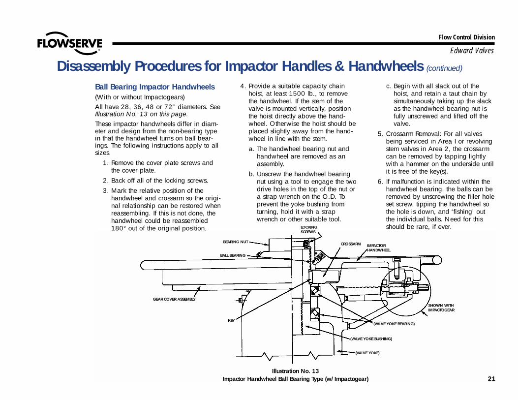
Ball Bearing Impactor Handwheels (With or without Impactogears)All have 28, 36, 48 or 72” diameters. SeeIllustration No. 13 on this page. These impactor handwheels differ in diam-eter and design from the non-bearing typein that the handwheel turns on ball bear-ings. The following instructions apply to allsizes.
1. Remove the cover plate screws andthe cover plate.
2. Back off all of the locking screws.3. Mark the relative position of the
handwheel and crossarm so the origi-nal relationship can be restored whenreassembling. If this is not done, thehandwheel could be reassembled180° out of the original position.
4. Provide a suitable capacity chainhoist, at least 1500 lb., to removethe handwheel. If the stem of thevalve is mounted vertically, positionthe hoist directly above the hand-wheel. Otherwise the hoist should beplaced slightly away from the hand-wheel in line with the stem.a. The handwheel bearing nut and
handwheel are removed as anassembly.
b. Unscrew the handwheel bearingnut using a tool to engage the twodrive holes in the top of the nut ora strap wrench on the O.D. Toprevent the yoke bushing fromturning, hold it with a strapwrench or other suitable tool.
c. Begin with all slack out of thehoist, and retain a taut chain bysimultaneously taking up the slackas the handwheel bearing nut isfully unscrewed and lifted off thevalve.
5. Crossarm Removal: For all valvesbeing serviced in Area I or revolvingstem valves in Area 2, the crossarmcan be removed by tapping lightlywith a hammer on the underside untilit is free of the key(s).
6. If malfunction is indicated within thehandwheel bearing, the balls can beremoved by unscrewing the filler holeset screw, tipping the handwheel sothe hole is down, and ‘fishing’ outthe individual balls. Need for thisshould be rare, if ever.
Illustration No. 13Impactor Handwheel Ball Bearing Type (w/Impactogear) 21

22
Flow Control Division
Edward Valves
Edward pressure-seal valves use varioustypes of Limitorque operators, dependingupon the size and pressure class, whichdetermines the torque requirements,whether the stem is revolving or non-revolv-ing, and whether the valve takes the stemthrust (torque-only unit) or the operatortakes the stem thrust (torque and thrustunit). The procedures below describe theremoval of these various types from thevalve yoke. Also included are completeinstructions for resetting the torque andlimit switches. Disassembly procedures forthe Limitorque operators themselves are notincluded and appropriate instructionsshould be obtained before starting.
On torque-only Limitorques, the operatorcan be removed while the valve is pressur-ized, but caution must be observed tomake certain that the valve is first in theback-seated or fully open position. See“Caution” on page 18.All of the following disassembly proceduresare arranged in accordance with thegeneral comments on page 18. Study thesepages carefully before beginning.First, determine whether the valve stem isrevolving or non-revolving. For non-revolv-ing stem valves, several procedures areshown, depending upon the operator type.Then determine whether the operator is atorque-only or torque and thrust unit.
Revolving Stem Valves or Non-Revolving Stem Valves with Torque-only Units All revolving stem valves use torque-onlyunits. The operator drive nut is connectedto the stem through a key. See IllustrationNo. 14. Non-revolving stem valves usingtorque-only units, have their drive nutsplined to the valve yoke bushing. SeeIllustration No. 15.
1. Disconnect the electrical wiring to theoperator.
2. Position a sling on the motor operatorand attach a chain hoist of suitablecapacity to the sling.
3. Remove the nuts from the undersideof the yoke flange.
Procedures for Removing Limitorque Operators from Valve Yokes
Illustration No. 14Torque-Only Limitorque Operator on Revolving Stem Valve (SMA or SMB)
Illustration No. 15Torque-Only Limitorque Operator on Revolving Stem Valve (SMB-4T or 5T)
Illustration No. 16Torque-Only Limitorque Operator on
Non-Revolving Stem Valve

23
Flow Control Division
Edward Valves
4. Lift the operator up and completelyoff the stem and stem key or the yokebushing splines.
5. Position the operator away to a cleanarea for further disassembly, ifrequired.
Non-Revolving Stem Valves withTorque and Thrust UnitsSee Illustration No. 17 on this page.
1. Disconnect the electrical wiring to theoperator.
2. Make certain the packing gland nutsare tight.
3. Position a chain hoist of suitablecapacity so the operator is supportedin such a manner that the handwheelcan still be rotated. If the valve isinstalled with its stem other than
vertical, the hoist should be posi-tioned slightly away from the hand-wheel in line with the stem.
4. Remove the nuts from the undersideof the yoke flange.
5. Turn the operator handwheel in adirection to close the valve, thusunscrewing the operator from thestem. Try to keep the weight on thehoist as the handwheel is turned.
6. With the hoist, lift the operator clearof the stem and place down on aclean area for further disassembly, ifrequired.
Procedures for Removing Limitorque Operators from Valve Yokes (continued)
Torque and Thrust Limitorque Operator on Non-Revolving Stem Valve

Limitorque Limit Switch and TorqueSwitch Setting ProceduresThe following descriptions apply only toLimitorque valve controls. If another typevalve control is used, the appropriate man-ual should be consulted to determine theproper setting of the limit switch andtorque switch.
Geared Limit Switch See Illustration No. 18.Numbers in parenthesis ( ) refer to call-outs on Illustration No. 18 on this page.When reassembling the Limitorque valvecontrol, the rotor type geared limit switchshould be reset as follows:
1. Make certain the electric current isoff.
2. Open the valve by hand until thevalve disk strikes the back seat. Notethe direction the intermittent gearshaft (D) is turning. This slotted shaftis extended through the gear caseand can be seen just above the rotorconnected to the open coil.
3. Back the valve off to allow for coastof the moving parts.
4. With the valve in this position,declutch the drive pinion (A) byinserting a screwdriver in the drivepinion setting rod (B) and turningclockwise until it is tight.The intermit-tent gear shaft (D) can now be turnedby inserting a screwdriver in its slot.
5. a. Turn the intermittent gear shaft (D)in the same direction as notedwhen the valve was opened untilthe contact on the rotor (C) con-nected to the open contactor cir-cuit opens.
b. In the event this contact is alreadyopen, turn this shaft in the oppo-site direction until it closes; thenback off on the shaft until the con-tact opens.
6. Unscrew the drive pinion setting rod(B) until it reaches a firm stop, but donot jam. This train of gears and con-tacts is now set.
� � � �
Illustration No. 18Limitorque Geared Limit Switch Assembly
WARNINGSHOULD IT BECOME NECESSARY TO
CHANGE THE TORQUE SWITCH SETTINGFOR ANY REASON, THE LOCAL EDWARDREPRESENTATIVE SHOULD BE CONTACTED
AND HE WILL OBTAIN FROM THE FACTORYTHE CORRECT NEW SETTING.
THE TORQUE SWITCH FOR THE MOTOR -OPERATED VALVE IS SET DURINGFACTORY ASSEMBLY TO CLOSE THE VALVE
AGAINST THE SPECIFIED UNBALANCEDPRESSURES AND REQUIRES THE SAME
ATTENTION FOR RESETTING.
24
Flow Control Division
Edward Valves
Procedures for Setting Actuator Torque and Limit Switches

25
Flow Control Division
Edward Valves
7. Connect the electric current andcheck this setting as follows: a. Run the valve to mid-position by
hand.b. Press the “open” pushbutton -
make sure moving the valve is inthe “open” direction.
c. Allow the limit switch to stop themotor.
d. After the motor has stopped, turnthe valve by hand to make suretheir is sufficient clearancebetween the valve backseat andthe position at which the valvestem comes to rest.
8. To set the position for operation ofthe indicating light, make sure thetorque switch is properly wired intothe closing circuit (see procedure forsetting torque switch below), and runthe valve to the closed position. Backthe valve off the seat to the desiredposition and set the “closed” light
contact using the same procedureoutlined under steps 4, 5a, 5b, and6, but use the intermittent gear shaftfor the light contacts.
9. When the settings are complete, thesetting rod should remain in the posi-tion described in step 6.
Torque Switch See Illustration No. 19.The procedure for setting the torque switch,both single and double, is as follows:
Single Torque Switch1. Make sure the electric current is off.2. Loosen the jam nut (F).3. Move the socket head adjusting
screw (G) in for light seating.4. Close the valve by the motor and
test for tightness of closing. If thevalve closes tightly enough, tightenthe jam nut.
5. For heavier seating move the adjust-ing screw (G) out and re-tighten thejam nut.
6. The threaded bushing (E) is intendedto limit the maximum setting of thistorque switch and is locked in posi-tion to limit the output torque to themaximum safe rating for the unit.
Double Torque Switch1. Make sure the electric current is off.2. Loosen the jam nut (F). Note: The
right side of this switch (K) normallylimits the torque applied in closingthe valve. There are cases of specialvalve assemblies where the right sideof this switch limits the torque in theopen direction. In all cases it isrecommended that this be checkedupon installation.
� � �
Illustration No. 19Single & Double Torque Switch Assemblies
�
Procedures for Setting Actuator Torque and Limit Switches (continued)

26
Flow Control Division
Edward Valves
3. Move the socket head adjustingscrew (H) in for light seating.
4. Close the valve by the motor and testfor tightness of closing. If the valvecloses tightly enough, tighten the jamnut.
5. For heavier seating move the adjust-ing screw (H) out and retighten thejam nut.
6. For setting the torque switch for theopening direction of valve travel, thesame procedure as outlined in steps2, 3, and 5 is followed, except thisadjustment is made on the left side ofthe switch, using the lower adjustingscrew.
7. The threaded bushing (J) is intendedto limit the maximum setting of thistorque switch and is locked in posi-tion to limit the output torque to themaximum safe rating for the unit.
Torque Switch SettingThe procedure outlined for setting torqueswitches is to be used only on occasionswhen maintenance on the switch itself oradjacent components require it.
Procedures for Setting Actuator Torque and Limit Switches (continued)
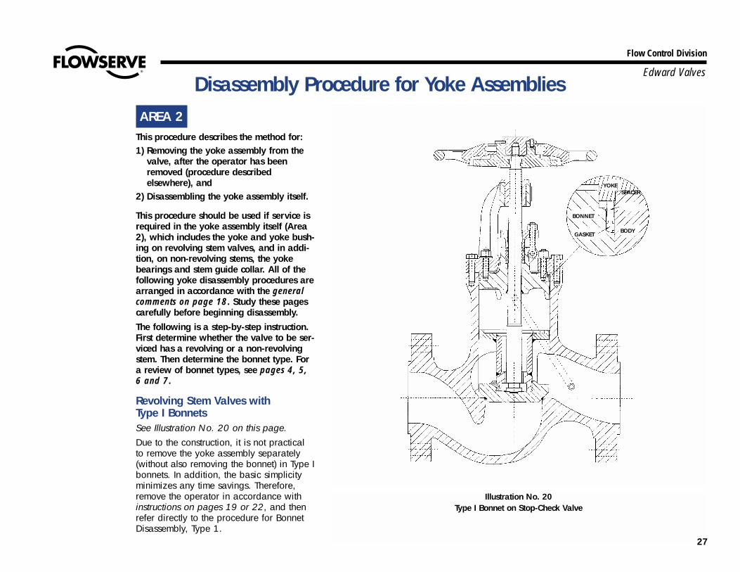
AREA 2This procedure describes the method for: 1) Removing the yoke assembly from the
valve, after the operator has beenremoved (procedure described elsewhere), and
2) Disassembling the yoke assembly itself.
This procedure should be used if service isrequired in the yoke assembly itself (Area2), which includes the yoke and yoke bush-ing on revolving stem valves, and in addi-tion, on non-revolving stems, the yokebearings and stem guide collar. All of thefollowing yoke disassembly procedures arearranged in accordance with the generalcomments on page 18. Study these pagescarefully before beginning disassembly.The following is a step-by-step instruction.First determine whether the valve to be ser-viced has a revolving or a non-revolvingstem. Then determine the bonnet type. Fora review of bonnet types, see pages 4, 5,6 and 7.
Revolving Stem Valves with Type I Bonnets See Illustration No. 20 on this page.Due to the construction, it is not practicalto remove the yoke assembly separately(without also removing the bonnet) in Type Ibonnets. In addition, the basic simplicityminimizes any time savings. Therefore,remove the operator in accordance withinstructions on pages 19 or 22, and thenrefer directly to the procedure for BonnetDisassembly, Type 1.
YOKE
GASKETBODY
BONNET
Illustration No. 20Type I Bonnet on Stop-Check Valve
27
Flow Control Division
Edward ValvesDisassembly Procedure for Yoke Assemblies
SPACER

28
Flow Control Division
Edward Valves
Revolving Stem Valves – Valves withType II Bonnets See Illustration No. 22 on page 30.
1. The manual or Limitorque operatormust first be removed in accordancewith instructions on pages 19 or 22.
2. Mark the body and yoke with prickpunch marks so that the parts are ref-erenced for reassembly.
3. Loosen the gland stud nuts.4. Remove the yoke stud nuts.5. Lift the yoke and stem to clear the
studs, and spin the yoke completelyoff the stem.
6. The yoke bushing can be removedfrom the yoke by breaking the tackwelds on the flats and unscrewing.
Non-Revolving Stem Valves –Valveswith either Type II or III BonnetsSee Illustrations No. 23 on page 31, andIllustration No. 24 on page 34.
1. The manual or Limitorque operatormust first be removed in accordancewith instructions on pages 19 or 22.
2. Mark the body, yoke, and yoke lockring with prick punch marks so that theparts are referenced for reassembly.
3. Make certain the packing gland nuts are tight.
4. Remove the yoke lock ring studs andnuts.
5. Remove the yoke lock ring using asmall pry bar to separate the halves.
6. Loosen the stem guide collar lock nut,back off the stem guide collar lockscrew and remove the stem guide col-lar key. Lift the collar to the top of thestem.
7. Turn the crossarm in a direction toclose the valve, thus unscrewing theyoke assembly from the stem.
8. If the valve is installed with its stemother than vertical, a chain hoist willhave to be attached to the yoke toallow the parts to turn freely.
9. With the hoist, lift the yoke assemblyclear of the stem and body assembly,simultaneously slipping the stemguide collar off of the stem.
10. Set the yoke assembly down on itsside and remove the hoist.
11. Disassembly of the yoke assemblyitself is as follows:
a. Remove the crossarm as explainedunder “Disassembly Procedure forImpactor Handles and Hand-wheels,” step 4, on page 20, orstep 5 on page 21. Be careful thatthe yoke bushing does not dropout of the yoke and bearings.
b. Prepare a bed of clean rags orpaper for the bearings and yokebushing.
c. While holding the yoke bushing,place a clean wood block over thetop and tap to drive the yoke bush-ing out of the bearings or yoke.
d. Remove the bearing washers (ifany) and the bearings from theyoke or yoke bushing, being verycareful not to contaminate thegrease with dirt of any kind. Keepthe bearings protected.
Valves with Type IV Bonnets See Illustration No. 27 on page 39.It is possible to remove the operator andyoke assembly as a unit on Type IVbonnets, but then it is not possible to dis-assemble the valve bonnet since use of theyoke is required. Therefore, only “Method2” is recommended for disassembly ofType IV bonnets. See page 19.
Disassembly Procedure for Yoke Assemblies (continued)

AREA 1 & 2This procedure describes the method forremoving the operator, either handwheelor Limitorque type, and yoke assemblyfrom the valve as a unit.This procedure should be used to removethe operator and yoke assembly in orderto gain access for servicing the valveinternals (Area 3), i.e., body, seats, bonnet,disk, etc. It is not suggested if service isrequired on either the operator (Area 1) oryoke assembly (Area 2) themselves.It has been arranged in accordance withthe general comments on page 18, and isspecifically referenced in “Method 1.”Study this carefully.Before beginning, first determine if thevalve has a revolving or non-revolvingstem. Then determine the bonnet type. Fora review of bonnet types, see pages 4, 5,6 and 7.
Revolving Stem Valves with Type I Bonnets See Illustration No. 20 on page 27.Due to the construction of Type I bonnets, it isnot practical to remove the yoke without alsoremoving the bonnet. Therefore, refer to page19 and use the “Method 2” procedure.
Revolving Stem Valves with Type II BonnetsSee valve Illustration No. 22 on page 30. See operator Illustration No. 14 onpage 22.
Impactor handwheels used on Type II bon-nets with revolving stems are not attachedto the yoke (only the stem) and the two,therefore, cannot be removed as a unit.Refer to page 19 and use the “Method 2”procedure.
On Limitorque-operated valves, due to theconstruction, it is not possible to removethe operator and yoke assembly as a unit.Therefore, refer to page 19 and use the“Method 2” procedure.
Illustration No. 21Type I Bonnet on Piston-Lift Check Valve 29
Flow Control Division
Edward Valves
Procedures for Removing Operator and Yoke Assembly as a Unit
GASKET
SPACER
BODY
COVER

Non-Revolving Stem Valves withType II, III, or IV BonnetsSee valve Illustrations No. 23 (page 31),No. 24 (page 34) and No. 27 (page 39).See Handwheel Illustrations 10, 11, and12 on pages 20 and 21. See LimitorqueIllustrations No. 16 (page 22) and 17(page 23).The following is applicable for ImpactorHandwheels and all types of Limitorqueoperators, including the XT type.
1. Disconnect the electrical wiring toLimitorque-operated valves.
2. Mark the body, yoke and yoke lockring with prick punch marks so thatthe parts are referenced forreassembly.
3. Make certain the packing gland nutsare tight.
4. Position a chain hoist of suitablecapacity so the operator and yokeassembly are supported in such a waythat the handwheel can still be rotated.If the valve is installed with its stemother than vertical, the hoist should bepositioned slightly away from thehandwheel in line with the stem.
5. Remove the yoke lock ring studs and nuts.
6. Remove the yoke lock ring using asmall pry bar to separate the halves.
7. Loosen the stem guide collar nut,back off the stem guide collar lockscrew and remove the stem guide col-lar key. Lift the collar to the top of thestem.
8. Turn the Impactor handwheel orLimitorque handwheel in a directionto close the valve, thus unscrewingthe operator yoke assembly from thestem. Keep the weight on the hoist asthe handwheel is turned to preventdamage to the stem threads. This isimportant.
9. With the hoist, lift the whole assem-bly clear of the stem simultaneouslyslipping the stem guide collar off ofthe stem.
Illustration No. 22Type II Bonnet on Revolving Stem Stop Valve
30
Flow Control Division
Edward Valves
Procedures for Removing Operator and Yoke Assembly as a Unit (continued)

AREA 3(For a definition of Area 3, see page 18)(See Illustration No. 5 on page 11 for anexplanation of valve parts nomenclature.)
Step-by-step disassembly procedures aredescribed for each of the four basic bonnettypes. For a review of bonnet types, referto pages 4, 5, 6 and 7. The proceduresfor each bonnet type include disassemblyinstructions for stop, stop-check (non-return), and piston-lift check valves. A sec-tion is also included under bonnet Type IIIfor tilting-disk check valves. The applicableinstructions should be read thoroughlybefore the start of disassembly.All of the following bonnet disassembly pro-cedures are arranged in accordance withthe general comments on page 18. Studythese pages carefully before beginning.
Type I Pressure-Seal Bonnets – Stopand Stop-Check (Non-Return) ValvesSee Illustration No. 20 on page 27.Note: All Type I bonnets have revolvingstems.
1. Loosen the gland bolt nuts and tapthe gland, which should relieve anypressure that might be trapped in thevalve. This is important.Note: Care must be taken in remov-ing the yoke stud nuts, in case theabove step has not relieved all pres-sure that might be trapped in the sys-tem. Once the yoke stud nuts arecompletely removed, the yoke-bonnet-
stem assembly is held only by the fric-tion of the pressure-seal gasketagainst the body bore. Trapped pres-sure could cause these parts to beblown out with considerable force.Therefore, care must be taken tobreak the bonnet and pressure-sealgasket loose before the yoke studnuts are completely removed.
2. Remove the crossarm by tapping witha hammer on the underside.
3. Carefully remove the yoke stud nuts, observing the cautionary note in step 1.
4. Remove half of the bonnet stud nuts,alternating to leave those remainingequally spaced.
5. Remove the gland bolt nuts.
Illustration No. 23Type II Bonnet on Non-Revolving Stem Stop Valve
31
Flow Control Division
Edward ValvesDisassembly Procedures for Bonnet Types
32
Flow Control Division
Edward Valves
6. Partially back off the remaining bon-net stud nuts. Raise the yoke, andinsert uniform shims in at least threeplaces between the yoke flange andthe body.
7. Raise the pressure-seal gasket bytightening the bonnet stud nuts uni-formly a fraction of a turn at a timeusing a star pattern. It is possible todamage the valve parts by cockingthe bonnet, so uniform turning ofthese nuts is very important. Notethat it will only be possible to raisethe gasket a distance equal to thethickness of the shims used in step 6.When this point is reached, the nutsshould be backed off again, moreshims added, and the process repeat-ed until the gasket comes free of thebody.
8. Use a chain hoist in line with thestem to lift the stem yoke bonnetassembly out of the body. During thisprocess, mark the body, yoke, bon-net, and pressure-seal gasket at cor-responding points (other than sealingsurfaces) so that their relative positioncan be duplicated in reassembly. Inlaying the parts aside for inspection,it is imperative that they be placedcarefully on a bed of rags or othersoft material to avoid marring anymachined surface, particularly anyseating and sealing surfaces.
9. Unscrew the stem from the yokebushing.
10. Remove the bonnet stud nuts;separate the yoke and bonnet.
11. On stop valves, the disk and disk-nut
assembly is attached to the stem. Onstop-check (non-return) valves, thepiston-disk assembly is not attachedto the stem and must be removedseparately. See step 12.
12. Screw 1/2”-13 bolts (3/8”-16 onsizes 5” and smaller) into the thread-ed bosses or nuts provided in the pis-ton. The piston can now be liftedfrom the valve. Occasionally a vacu-um may be formed by the coolingfluid in the pipe line below the valve.Until relieved, this vacuum will pre-vent removal of the piston. Since thepiston must be removed through thepressure-seal area of the bonnetbore, use caution to avoid marringthe scaling surface in any way.
13. The bonnet end opening should bekept covered whenever possible.
Type I Pressure-Seal BonnetsPiston-Lift Check Valves See Illustration No. 21 on page 29.Piston-lift check valves are constructed withvalve bodies similar to the correspondingstop or stop-check (non-return type) valves.Assembly is simplified by the absence of ayoke and stem.Note: Care must be taken in removing thecover retainer nuts, in case pressure shouldbe trapped in the body (down-stream pip-ing). Check to make certain all down-stream pressure is relieved. Once the coverretainer nuts are completely removed, thecover/cover retainer assembly is held onlyby the friction of the pressure-seal gasketagain the body bore. Trapped pressurecould cause these parts to be blown out
with considerable force. Therefore, caremust be taken to relieve all pressure, andbreak the cover and pressure-seal gasketloose before the cover retainer nuts arecompletely removed.
1. Carefully remove the cover retainernuts, observing the above caution.
2. Remove half of the cover stud nuts,alternating to leave those remainingevenly spaced.
3. Partially back off the remaining bon-net stud nuts or cap screws. Raise thecover retainer and insert uniformshims in at least three places betweenthe cover retainer and body.
4. Raise the pressure-seal gasket bytightening the bonnet stud nuts or capscrews uniformly, a fraction of a turnat a time using a star pattern. It ispossible to damage the valve partsby cocking the cover, so uniform turn-ing is very important. Note that it willonly be possible to raise the gasket adistance equal to the thickness of theshims used in step 3. When this pointis reached, the nuts or cap screwsshould be backed off again, moreshims added, and the process repeat-ed until the gasket comes free of thebody.
5. Lift the cover/cover retainer assemblyout of the valve. During this process,mark the body, cover/cover retainer,and pressure-seal gasket at corre-sponding points (but not on sealingsurfaces) for reference and reassem-bly.
Disassembly Procedures for Bonnet Types (continued)

33
Flow Control Division
Edward Valves
In larger sizes where this assembly istoo heavy to manhandle, remove thecover/cover retainer and install aneyebolt in the threaded hole in thecover. Use the eyebolt to fasten achain hoist directly above the valvecenterline. In laying the parts asidefor inspection, it is imperative thatthey be placed carefully on a bed ofrags or other soft material to avoidmarring any machined surface,particularly any seating and sealingsurfaces.
6. Screw 1/2”-13 bolts (3/8”-16 onsizes 5” and smaller) into the thread-ed bosses or nuts provided in the pis-ton. The piston can now be liftedfrom the valve. Until relieved, thisvacuum will prevent removal of thepiston. Since the piston must beremoved through the pressure-sealarea of the bonnet bore, use cautionto avoid marring the sealing surfacein any way.
7. The bonnet end opening should bekept covered whenever possible.
Type II Pressure-Seal Bonnets – Stopand Stop-Check (Non-Return) Valveswith Revolving Stems
See Illustration No. 22 on page 30.*1. Remove the crossarm by tapping with
a hammer on the underside.*2. Mark the body and yoke with prick
punch marks so that the parts can bereassembled in their original position.
*3. Remove the yoke stud nuts.
4. Remove the gland stud nuts andgland.
*5. Lift the yoke and stem to clear thestuds, and spin the yoke completelyoff the stem.
6. Mark the bonnet, bonnet retainerring, and body with adjacent prickpunch marks so that their relativeposition can be duplicated inreassembly.
7. Replace the crossarm and handwheelnut on the stem and with a chainhoist mounted in line with the stem,pull the stem up snugly against thebonnet backseat. On Limitorque-operated valves, thread an eyeboltinto the threaded top end of the stem.
8. Loosen the bonnet retainer capscrews.
9. Unscrew the bonnet retainer ring.10. With clean rags and an air hose,
thoroughly clean the bonnet and gasket retainer segments. This isimportant.
11. Slack off the chain hoist slightly. If thebonnet does not drop away from thepressure-seal gasket, tap gently untilit does. When the bonnet is free,lower it as far as it will go into thebody.
12. With a copper or brass drive pin, orsmall clean hardwood block, drivethe gasket retainer segments down-ward to the bottom of the retainergroove (about 1/16”) in the body.
13. Remove the gasket retainer segments.
14. Lift the bonnet into contact with thepressure-seal gasket, again using thechain hoist.
15. Screw back on the bonnet retainerring, using shims to provide addition-al clearance for further upwardmovement of the bonnet.
16. Use three or four nuts, in a uniformspacing on the bonnet studs, to pullthe bonnet and pressure-seal gasketout of the body. All nuts should beturned uniformly, a fraction of a turnat a time using a star pattern. It ispossible to damage valve parts bycocking the bonnet, so uniform turn-ing of the nuts is very important.
17. Remove the stem and bonnet assem-bly. During this process, mark thespacer ring and pressure-seal gasketat points (other than sealing surfaces)corresponding to the previous markon the body (see step 6). In layingthe parts aside for inspection, it isimperative that they be placed care-fully on a bed of rags or other softmaterial to avoid marring anymachined surface, particularly anyseating and sealing surfaces.
18. On stop valves, the disk and disk-nutassembly is attached to the stem. Onstop-check (non-return) valves, thepiston-disk assembly is not attachedto the stem and must be removedseparately. See step 19.
Disassembly Procedures for Bonnet Types (continued)

Flow Control Division
Edward Valves
19. Screw 1/2”-13 bolts (3/8”-16 onsizes 5” and smaller) into the thread-ed bosses or nuts provided in the pis-ton. The piston now can be liftedfrom the valve. Occasionally, a vacu-um may be formed by the coolingfluid in the pipe line below the valve.Until relieved, this vacuum will pre-vent removal of the piston. Since thepiston must be removed through thepressure-seal area of the bonnetbore, use caution to avoid marringthe sealing surface in any way.
20. The bonnet end opening should bekept covered whenever possible.
Type II Pressure-Seal Bonnets – Stopand Stop-Check (Non-Return) Valveswith Non-Revolving StemsSee Illustration No. 23 on page 31.*1. Mark the body, yoke and yoke lock
ring with prick punch marks so thatthe parts can be reassembled in theiroriginal position.
*2. Remove the yoke lock ring studs andnuts.
*3. Remove the yoke lock ring using asmall pry bar to separate the halves.
*4. Loosen the stem guide collar lock nut,back off the stem guide collar lockscrew, and remove the stem guidecollar key.
*5. Turn the crossarm in a direction toclose the valve, thus unscrewing theyoke from the stem. The stem must berestrained from turning; a flat toolheld in the stem guide collar key slot
is convenient, being careful not todamage the slot.
*6. If the valve is installed with its stemother than vertical, attach the chainhoist to the yoke in such a manner asto permit rotation of the crossarm.
*7. With the chain hoist, lift the yokeassembly clear of the stem and bodyassembly, simultaneously slipping thestem guide collar off the stem.
8. Mark the bonnet, bonnet retainerring, and body with adjacent prickpunch marks so that their relativeposition can be duplicated inreassembly.
9. Remove the gland bolt nuts andgland.
10. Place an eyebolt in the threaded endof the stem.
Disassembly Procedures for Bonnet Types (continued)
Illustration No. 24Type III Bonnet on Stop Valve
SHOWN WITHIMPACTOGEAR
34

Flow Control Division
Edward Valves
11. With a chain hoist mounted in linewith the stem and fastened to the eye-bolt, pull the stem into firm contact atthe bonnet backseat.
12. Loosen the bonnet retainer capscrews.
13. Unscrew the bonnet retainer ring.14. With clean rags and an air hose,
thoroughly clean the top of the valveand all exposed surfaces of the bon-net and gasket retainer segments.This is important.
15. Slack off the chain hoist slightly. If thebonnet does not drop away from thepressure-seal gasket, tap gently untilit does. When the bonnet is free,lower it into the body to clear thegasket retainer segments.
16. With a copper or brass drive pin, ora small clean hardwood block, drivethe gasket retainer segments down-ward to the bottom of the retainergroove (about 1/16”) in the body.
17. Remove the gasket retainer segments.18. Lift the bonnet into contact with the
pressure-seal gasket, again using thechain hoist.
19. Screw back on the bonnet retainerring, using shims to provide addition-al clearance for further upward move-ment of the bonnet.
20. Use three or four nuts, in a uniformspacing on the bonnet studs, to pullthe bonnet and pressure-seal gasketout of the body. All nuts should beturned uniformly, a fraction of a turn
at a time using a star pattern. It ispossible to damage the valve partsby cocking the bonnet, so uniformturning of the nuts is very important.
21. Remove the stem and bonnet assem-bly. During this process, mark thespacer ring and pressure-seal gasketat points (other than sealing surfaces)
corresponding to the previous markon the body (see step 8). In layingthe parts aside for inspection, it isimperative that they be placed care-fully on a bed of rags or other softmaterial to avoid marring anymachined surface, particularly anyseating and sealing surfaces.
Disassembly Procedures for Bonnet Types (continued)
Illustration No. 25Type III Bonnet on Piston-Lift Check Valve
SPACER RING
GASKETRETAINER
GASKETBODY
COVER
35

36
Flow Control Division
Edward Valves
22. On stop valves, the disk and disk-nutassembly is attached to the stem. Onstop-check (non-return) valves, the pis-ton-disk assembly is not attached tothe stem and must be removed sepa-rately. See step 23.
23. Screw 1/2”-13 bolts (3/8”-16 onsizes 5” and smaller) into the thread-ed bosses or nuts provided in the pis-ton. The piston can now be liftedfrom the valve. Occasionally a vacuum may be formed by the cool-ing fluid in the pipe line below thevalve. Until relieved, this vacuum willprevent removal of the piston. Sincethe piston must be removed throughthe pressure-seal area of the bonnetbore, use caution to avoid marringthe sealing surface in any way.
24. The bonnet end opening should bekept covered whenever possible.
Type III Pressure-Seal Bonnets –Stop and Stop-Check (Non-Return)ValvesSee Illustration No. 24 on page 34.*1. Mark the body, yoke and yoke lock
ring with prick punch marks so theparts can be reassembled in theiroriginal position.
*2. Remove the yoke lock ring studs andnuts.
*3. Remove the yoke lock ring using asmall pry bar to separate the halves.
*4. Loosen the stem guide collar lock nut,back off the stem guide collar lockscrew and remove the stem guidecollar key.
*5. Turn the crossarm in a direction toclose the valve, thus unscrewing theyoke from the stem. The stem must berestrained from turning; a flat toolheld in the stem guide collar key slotis convenient, being careful not todamage the slot.
*6. If the valve is installed with its stemother than vertical, attach the chainhoist to the yoke in such a manner asto permit rotation of the crossarm.
*7. With the chain hoist, lift the yokeassembly clear of the stem and bodyassembly, simultaneously slipping thestem guide collar off the stem.
8. Mark the bonnet, bonnet retainerring, and body with adjacent prickpunch marks so their relative positioncan be duplicated in reassembly.
9. Remove the gland bolt nuts andgland.
10. Screw an eyebolt in the threaded endof the stem.
11. With the chain hoist mounted in linewith the stem and fastened to the eye-bolt, pull the stem into firm contact atthe bonnet backseat.
12. Remove the bonnet stud nuts andbonnet retaining ring.
13. With clean rags and air hose, thor-oughly clean the top of the valve andall exposed surfaces of the bonnetand gasket retainer segments. This isimportant.
14. Slack off the chain hoist slightly. If thebonnet does not drop away from thepressure-seal gasket, tap gently until
it does. When the bonnet is free,lower it as far as it will go into thebody.
15. With a copper or brass drive pin, ora clean hardwood block, drive thegasket retainer segments downwardto the bottom of the retainer groove(about 1/16”) in the body.
16. Remove the gasket retainer segments.17. Lift the bonnet into contact with the
pressure-seal gasket, again using thechain hoist.
18. Replace the bonnet retainer ring,using shims to provide additionalclearance for further upward move-ment of the bonnet.
19. Use three or four nuts in a uniformspacing on the bonnet studs to pullthe bonnet and pressure-seal gasketout of the body. All nuts should beturned uniformly, a fraction of a turnat a time using a star pattern. It ispossible to damage valve parts bycocking the bonnet, so uniform turn-ing of the nuts is very important.
20. Remove the stem and bonnet assem-bly. During this process, mark thespacer ring and pressure-seal gasketat points (other than seal-surfaces)corresponding to the previous markon the body (see step 8). In layingthe parts aside for inspection, it isimperative that they be placed care-fully on a bed of rags or other softmaterial to avoid marring anymachined surface, particularly anyseating and sealing surfaces.
Disassembly Procedures for Bonnet Types (continued)

37
Flow Control Division
Edward Valves
21. On stop valves, the disk and disk-nutassembly is attached to the stem. Onstop-check (non-return) valves, the pis-ton-disk assembly is not attached tothe stem and must be removed sepa-rately. See step 22.
22. Screw 1/2”-13 bolts (3/8”-16 onsizes 5” and smaller) into the thread-ed bosses or nuts provided in the pis-ton. The piston now can be liftedfrom the valve. Occasionally, a vacu-um may be formed by the coolingfluid in the pipe line below the valve.Until relieved, this vacuum will pre-vent removal of the piston. Since thepiston must be removed through thepressure-seal area of the bonnetbore, use caution to avoid marringthe sealing surface in any way.
23. The bonnet end opening should bekept covered whenever possible.
Type III Pressure-Seal Bonnets –Piston-Lift Check ValvesSee Illustration No. 25 on page 35.
1. Remove the cover/cover retainer.2. Screw an eyebolt into the tapped
hole in the cover.3. Fasten a chain hoist to the eyebolt
and pull up just enough to eliminateall slack in the hoist.
4. Remove all cover stud nuts or capscrews.
5. Remove the cover retainer.6. Mark the body, cover and gasket
retainer segments with adjacent prick
punch marks so that their relative posi-tion can be restored on reassembly.
7. With clean rags and an air hose,thoroughly clean the top of the valveand all exposed surfaces of the coverand gasket retainer segments. This isimportant.
8. Slack off on the chain hoist to permitthe cover to slip down into the valvebody. If necessary, tap lightly toloosen. If the cover resists all attemptsto force it into the valve body, high-pressure fluid may be trapped in thebonnet cavity (and downstream) ofthe check valve. The cover will dropeasily when this pressure is relieved.Lower the cover until it rests on top ofthe valve piston.
9. With a copper or brass drive pin ora clean hardwood block, drive thegasket retainer segments downwardto the bottom of the retainer groove(about 1/16”) in the body.
10. Remove the gasket retainer segments.11. Lift the cover back into contact with
the pressure-seal gasket, again usingthe chain hoist.
12. Replace the cover retainer, usingshims to provide additional clearancefor further upward movement of thecover.
13. Use three or four nuts in a uniformspacing on the bonnet studs to pullthe cover and gasket out of the body.All nuts or screws should be turneduniformly, a fraction of a turn at atime, using a star pattern. It is possi-
ble to damage valve parts by cock-ing the cover, so uniform turning ofthe nuts is very important.
14. Lift out the cover assembly. Duringthis process, mark the spacer ringand pressure-seal gasket at points(other than the sealing surfaces) cor-responding to previous marks on thebody and cover (see step 6). In lay-ing the parts aside for inspection, it isimperative that they be placed care-fully on a bed of rags or other softmaterial to avoid marring anymachined surface, particularly anyseating and sealing surfaces.
15. Screw 1/2”-13 bolts (3/8”-16 onsizes 5” and smaller) into the thread-ed bosses or nuts provided in the pis-ton. The piston can now be liftedfrom the valve. Occasionally a vacu-um may be formed by the coolingfluid in the pipe line below the valve.Until relieved, this vacuum will pre-vent removal of the piston. Since thepiston must be removed through thepressure-seal area of the bonnetbore, this must be done very carefullyto avoid marring the sealing surfacein any way.
16. The bonnet end opening should bekept covered whenever possible.
Disassembly Procedures for Bonnet Types (continued)

38
Flow Control Division
Edward Valves
Type III Pressure-Seal Bonnets –Tilting Disk Check Valves Sizes 6”and larger.See Illustration No. 26 on page 38.As explained under “Seat and DiskRepairs” on page 14, this manual does notinclude information for repair of the seatand disk of Tilting Disk Check Valves.Consult your Edward Sales Representative.
1. Remove the cover/cover retainer.2. Screw an eyebolt into the tapped
hole in the cover.3. Fasten a chain hoist to the eyebolt
and pull up just enough to eliminateall slack in the hoist.
4. Remove all cover stud nuts or capscrews.
5. Remove the cover retainer.6. Mark the body, cover and gasket
retainer segments with adjacent prickpunch marks so that their relative posi-tion can be restored on reassembly.
7. With clean rags and an air hose,thoroughly clean the top of the valveand all exposed surfaces of the coverand gasket retainer segments. This isimportant.
8. Slack off on the chain hoist to permitthe cover to slip down into the valvebody. If necessary, tap lightly toloosen. If the cover resists any rea-sonable attempts to force it into thevalve body, high-pressure fluid maybe trapped in the bonnet cavity (anddownstream) of the check valve. The
cover will drop easily when this pres-sure is relieved. Lower the cover untilit rests on top of the disk.
9. With a copper or brass drive pin ora clean hardwood block, drive thegasket retainer segments downwardto the bottom of the retainer groove(about 1/16”) in the body.
10. Remove the gasket retainer segments.11. Lift the cover back into contact with
the pressure-seal gasket, again usingthe chain hoist.
12. Replace the cover retainer, usingshims to provide additional clearancefor further upward movement of thecover.
13. Use three or four nuts or screws in auniform spacing on the bonnet studsto pull the cover and gasket out of thebody. All nuts or screws should beturned uniformly, a fraction of a turnat a time, using a star pattern. It ispossible to damage valve parts bycocking the cover, so uniform turningof the nuts is very important.
Disassembly Procedures for Bonnet Types (continued)
Illustration No. 26Type III Bonnet on Tilting Disk Check Valve
LIFT HAND WOUND SPRING COLORED GREEN AND ASSEMBLED ON THIS SIDE

14. Lift out the cover assembly. During thisprocess, mark the spacer ring andpressure-seal gasket at points (otherthan the sealing surfaces) correspond-ing to the previous marks on the bodyand cover (see step 6). In laying theparts aside for inspection, it is impera-tive that they be placed carefully on abed of rags or other soft material toavoid marring any machined surface,particularly any seating and sealingsurfaces.
15. Inspection of the seat and hinge pins canbe made without further disassembly.
16. If removal of the disk is necessary,proceed as follows:NOTE: Pressure may be trapped inthe valve even though the system isdown, and care must be taken inremoving the hinge pin retainer. Oncethe retainer bolts are completelyremoved, the hinge pins are heldonly by the friction of the pressure-seal gasket against the hinge pinbore. Trapped pressure could causethe retainer and hinge pin to beblown out with considerable force.Therefore, care must be taken tobreak the hinge pin and hinge pinpressure-seal gasket loose before thethree retainer bolts are completelyremoved.a. Carefully loosen, but do not
remove, the hinge pin retainerbolts.
b. Place a suitable spacer betweenthe hinge pin retainer and thebody. Insert a threaded stud (samethread as the retainer bolts)
through the center hole of thehinge pin retainer and thread intothe puller hole in the hinge pin.
c. Support the disk inside the body;thread a nut onto the stud, andtighten the nut until the pressure-seal gasket and hinge pin is looseand any pressure that may betrapped in the valve is relieved. Ifthe hinge pin will not move, heatthe body boss (not more than 300° F) with an acetylene torch.
d. Remove the hinge pin retainerbolts, hinge pin retainer, roll pin,hinge pin, pressure-seal gasketand torsion spring. During thisprocess, mark the position of thehinge pin relative to the body withprick punch marks. Tag eachhinge pin and torsion spring sothat each may be replaced on theproper side of the valve. The tor-sion springs are wound counter toeach other to provide a slightrestraint to valve opening andassist in valve closing, making itextremely important to reassemblethem correctly.
e. Remove the other hinge pin.f. The disk can now be removed from
the body. Use caution not to dam-age any machined or seating sur-faces. In laying the parts aside forinspection, it is imperative that theybe placed carefully on a bed ofrags or other soft material to avoiddamage.
17. The cover end opening should bekept covered whenever possible.
Type IV Pressure-Seal Bonnets –Stop and Stop-Check (Non-Return)ValvesSee Illustration No. 27.NOTE: All Type III Bonnets have non-revolving stems.
1. Mark the body, yoke and yoke lockring with prick punch marks so thatthe parts can be reassembled in theiroriginal position.
2. Loosen the gland bolt nuts and tapthe gland, which should relieve anypressure that might be trapped in thevalve. This is important.
SHOWN WITHIMPACTOGEAR
Illustration No. 27Type IV Bonnet on Stop-Check Valve
39
Flow Control Division
Edward ValvesDisassembly Procedures for Bonnet Types (continued)
40
Flow Control Division
Edward Valves
3. Remove the bonnet retainer ring capscrews. Due to space limitations, aspecial tool may have to be used.Make it from a standard Allen socketwrench.
4. Open the valve fully so the stem isback-seated on the bonnet and im-pact with the handwheel severaltimes to break the pressure-seal gas-ket loose from the body. Once thegasket is free, discontinue turning thehandwheel.
5. Remove the yoke lock ring studs andnuts.
6. Remove the yoke lock ring using asmall pry bar to separate the halves.
7. To make certain the pressure-seal gas-ket is free in the body, attach a chainhoist to the handwheel and lift theyoke and bonnet assembly up a max-imum of 1/4”. Do this with a hoist ofat least 1000 lb. capacity. If the stemof the valve is not mounted vertically,position the hoist slightly away fromthe handwheel in line with the stem.
8. Lower the hoist and valve assemblyback to a slack position.
9. Loosen the stem guide collar lock nut,back off the stem guide collar lockscrew and remove the stem guide collar key.
10. Turn the crossarm in a direction toclose the valve thus unscrewing theyoke from the stem. The stem must berestrained from turning; a flat toolheld in the stem guide collar key slotis convenient, being careful notdamage the slot.
11. The hoist may have to be used forstep 10, if the stem is not vertical, toallow the parts to turn freely.
12. Lift the yoke assembly clear of the stemand body assembly, simultaneouslyslipping the stem guide collar off of thestem.
13. Mark the bonnet, bonnet retainer ringand body with adjacent prick punchmarks so that their relative positioncan be duplicated in reassembly.
14. Remove the gland bolt nuts andgland.
15. Remove the bonnet retainer ring.16. With clean rags and air hose, thor-
oughly clean the top of the valve andall exposed surfaces of the bonnetand pressure-seal gasket. This isimportant.
17. Mark the pressure-seal gasket at apoint (other than seal surfaces) corre-sponding to the previous mark on thebody (see step 13).
18. Screw an eyebolt in the threaded endof the stem.
19. For Stop Valves:a. With the chain hoist mounted in
line with the stem and fastened tothe eyebolt, pull the stem, bonnetand pressure-seal gasket out of thevalve so the disk nut contacts thegasket retainer segments. Back off1/8”.
b. Slide the bonnet, spacer ring (ifused) and pressure-seal gasket upto the top of the stem and fasten inplace by wrapping the stem withelectrical tape, or other suitablemeans.
20. For Stop-Check (non-return) Valves:With the chain hoist mounted in linewith the stem and fastened to the eye-bolt, pull the stem, bonnet, spacer ring(if used), and pressure-seal gasket com-pletely out of the valve. In laying theparts aside for inspection, it is impera-tive that they be placed carefully on abed of rags or other soft material toavoid marring any machined surface,particularly any seating and sealingsurfaces.
21. With a copper or brass drift pin, or aclean hardwood block, tap the gas-ket retainer segments to free them inthe body retainer groove. (Note thatthey cannot be driven downward inType IV construction.)
22. Remove the gasket retainer segmentsusing two pieces of approximately3/32 diameter wire bent 90°, halfan inch from the end. Insert the bentend into the 1/8” holes provided forthis, removing each segment one at atime.
23. For stop valves, remove the stem anddisk assembly from the valve, and lay itdown carefully as explained in step 20.
24. For stop-check (non-return) valves, thepiston-disk assembly is not attachedto the stem and must be removed sep-arately. Reach down into the body
Disassembly Procedures for Bonnet Types (continued)

41
Flow Control Division
Edward Valves
bore and lift out the piston, beingcareful not to mar any sealing sur-faces such as the body pressure-sealarea or piston seating surface. Occa-sionally a vacuum may be formed bythe cooling fluid in the pipe linebelow the valve. Until relieved, thisvacuum will prevent removal of thepiston.
25. The bonnet end opening should bekept covered whenever possible.
Type IV Pressure-Seal Bonnets –Piston-Lift Check ValvesSee Illustration No. 28.
1. If used, remove the cover/coverretainer.
2. NOTE: Make certain all pressure isrelieved in the valve body (down-stream piping). Once the cover retainer bolts or nuts are completelyremoved, the cover/cover retainerassembly is held against the bodybore only by the friction of the pres-sure-seal gasket. Trapped pressurecould cause the cover/cover retainerassembly to be blown out with con-siderable force. Therefore, care mustbe taken to break the cover and pres-sure-seal gasket loose before thecover retainer bolts or nuts are com-pletely removed.
3. Carefully loosen, but do not remove,the cover retainer bolts or nuts. Ifused, loosen the large bolt in the cen-ter of the cover retainer.
4. Mark the body and cover retainer atcorresponding points for referenceand reassembly.
5. Place a suitable spacer between thecover retainer and the body. Unlessalready equipped, insert a threadedstud through the center hole of thecover retainer and thread into thepuller hole in the cover.
6. Place a heavy washer over the studto bridge the cover retainer hole andthread a nut onto the stud. Tightenthe nut (or the large center bolt) untilthe pressure-seal gasket and cover isloose and any pressure is relieved.
7. Remove the cover retainer bolts ornuts and draw the cover/cover retain-er assembly out of the body. An eye-bolt may be inserted in the threadedcover hole and the assembly liftedout with a chain hoist, if desired. Inlaying the parts aside for inspection,it is imperative that they be placedcarefully on a bed of rags or othersoft material to avoid marring anymachined surface.
8. Before disassembling the cover/coverretainer assembly, mark the coverand pressure-seat gasket at points(other than sealing surfaces) corre-sponding to the previous mark on thecover retainer (see step 4).
9. With a copper or brass drift pin or aclean hardwood block, tap the gas-ket retainer to free them in the bodyretainer groove. (Note that they can-not be driven downward in Type IVconstruction.)
10. Remove the gasket retainer segmentsusing two pieces of approximately3/32 diameter wire bent 90°,half aninch from the end. Insert the bent endinto the 1/8“ holes provided for this,removing each segment one at a time.
11. Remove the piston by reaching downinto the body bore and lifting out,being careful not to mar any sealingor seating surfaces such as the bodypressure-seal area or piston seatingsurface. Occasionally a vacuum maybe formed by the cooling fluid in thepipeline below the valve. Untilrelieved, this vacuum will preventremoval of the piston.
12. The bonnet end opening should bekept covered whenever possible.
Disassembly Procedures for Bonnet Types (continued)
Illustration No. 28Type IV Bonnet or Piston-Lift Check Valve

42
Flow Control Division
Edward Valves
It is important to determine that the newcomposite pressure-seal gasket, the bonnetand the body sealing area are in satisfac-tory condition before installation. The fol-lowing steps will help ensure superior per-formance of the gasket.
1. Carefully inspect the body bore andbonnet O.D. sealing surfaces.Remove any raised metal from theentry chambers and gasket chamberregions. Repair any gouges in thesealing region in accordance with theinstructions on page 10.
2. Inspect the new composite gasket.Note: All composite gaskets havecracks and wrinkles in the flexiblegraphite. This is a normal result ofthe forming process and will notaffect gasket performance.
3. Be sure the anti-extrusion rings aretightly bonded to the graphitic gas-ket, so they will not touch the bodyduring assembly. If any of the anti-extrusion rings are loose, carefullyscrape away all flexible graphite lefton the anti-extrusion ring surface andre-bond to the graphite surface usingLoctite 454 or other suitable contactcement. The ends of the outer ringsshould touch after bonding. Thereshould be an approximate .020 ±.005” gap at the ends of the innerring.
4. Place the gasket on the bonnet withthe two anti-extrusion rings facing upas shown in the illustration. The gas-ket should fit snugly around the bon-net, and the gasket O.D. should not
exceed the O.D. of the bonnet. Thiswill ensure that the gasket does notcatch on the body and “energize”prematurely.
5. Install the spacer ring on the bonnetas shown with the wide end towardthe gasket. Now the valve may bereassembled using the assemblyprocedures described in the followingsections for different types of bonnets,except that special torqueingprocedures are required as describedin the following:
IMPORTANT: The composite pressure-sealmust remain dry until fully compactedfor proper sealing!6. Once the bonnet and bonnet retainer
holes have been aligned, lightly lubri-cate the fasteners with high-tempera-ture anti-seize lubricant. Assemble theBelleville washers under the nuts orcapscrews. Assemble remaining partsas described in previous sections.
7. Preload the bonnet by pulling up witha well-centered crane load or withcome-alongs.
Assembly of Composite Pressure-Seal Gaskets
BELLEVILLEWASHERS
GASKETRETAINER
SPACERRING
COMPOSITEGASKET
Table C
Composite Gasket Bonnet/CoverBolt/Nut Pull-Up Torques
(For Initial Pull-Up)
Bolt Size Required Torqueft.-lbs.
3/8 307/16 451/2 709/16 1005/8 1353/4 2207/8 3501 540
1-1/8 7701-1/4 11001-3/8 15001-1/2 17001-5/8 23001-3/4 32001-7/8 4200
2 4600

43
Flow Control Division
Edward Valves
8. Initially compress the pressure-sealgasket, making sure that the bonnetdoes not cock in the body.
9. While maintaining the pull-up load,torque the bonnet/cover bolts evenlyusing a varying star pattern, until thefastener torques reach a value of 2/3or the torque given in Table C onpage 42.
10. After reaching 2/3 of the torquevalue given in Table C on page 42,torque the bonnet nuts in smalltorque increments, with no morethan 1/16 turn per tighteninground, using a varying star pattern,until the full torque value given inTable C on page 42, is reached.
11. Re-torque the bolts at the finaltorque value several times, until thegasket no longer compresses. Thisstep is necessary due to the highresilience of the graphitic gasket.
12. Complete remaining valve assemblyin accordance with the appropriatepreceding section of this manual.
13. When the valve is next under pres-sure, either during system hydrostat-ic test or when put in service, re-torque the bolts to the torque valuesgiven in Table B on page 10.
CAUTIONDo not use the torque
values in Table C on page 42while the valve is under pressure.
IntroductionThe reassembly procedures in this manualare not as detailed as the disassemblyinstructions since, in many cases, just areverse procedure is used. However, step bystep instructions are provided for each of thefour bonnet types. In addition, the followinggeneral points should be considered.
1. The most important consideration inthe reassembly of pressure-seal valvesis cleanliness. All flaky scales shouldbe removed with a wire brush, emerycloth, or acid solvent. Oil and greaseshould be removed from all partswith a suitable solvent to prevent anyforeign matter from collecting on seal-ing and seating surfaces.
2. Unless it is impossible to do so, use a new pressure-seal gasket whenreassembling a bonnet that has beendisassembled, whether it was leakingor not.
3. When reassembling valve bonnets,always examine the stem packingand replace if necessary.
4. Observe all of the reference marks orprick punch marks assigned duringdisassembly so that the original partrelationships can be maintained.
5. Reassemble stud nuts and cap screwsusing the torque values given in TableB on page 10.
6. When reassembling the bearings inthe yoke assembly of non-revolvingstem valves, use the following proce-dure to obtain the proper bearingpreload:Handwheel Operated Valvesa. Close the valve hand tight.b. Impact the handwheel.
1) Two men, one blow for valveswith spherical roller bearings.
2) One man, one blow for valveswith tapered roller bearings.
c. Tighten the handwheel bearingnut, using a tool to engage the twodrive holes in the top or a strap
Reassembly Procedures for Metal Pressure-Seal Valves
Assembly of Composite Pressure-Seal Gaskets (continued)

44
Flow Control Division
Edward Valves
wrench on the O.D. Use a reason-able length of bar stock, or ade-quate size strap wrench, so the nutis firmed up well.
d. Tighten the set screws in the hand-wheel bearing nut against the yokebushing. This completes the pre-loading of the lower bearing.
e. If desired, the valve can now beclosed tightly for a seat joint test.
f. To preload the upper bearing,open the valve fully to the bonnetbackseat so it is hand tight.
g. Repeat step b.h. Loosen the set screws in the hand-
wheel bearing nut.i. Repeat step c. Attempt to line up
the existing set screw holes in thehandwheel bearing nut with thosein the yoke bushing. This will dupli-cate the original factory preload.However, it is important that thepreloading be performed asdescribed above and if the holescannot be lined up, new onesshould be drilled and tapped.When drilling, be careful that nochips enter the yoke bushing-stemthreads.
j. Refasten the safety wire.
Limitorque Motor-Operated ValvesThis preloading procedure appliesonly to the yoke bearings (on non-revolving stem valves) on valves usingoperators of the ‘torque-only’ type.Valves using torque and thrust units
do not have bearings (they are in theoperator instead). For an explanationof the various operator types, refer tothe section “Procedure for RemovingLimitorque Operators from ValveYokes” on page 22.a. Turn the manual handwheel on the
Limitorque operator to apply 10%of the handwheel torque requiredto seat the valve against maximumpressure.
b. Tighten the yoke bushing nut so thekeyways in the yoke bushing andthe nut line up, and insert the key.This completes the preloading ofthe lower bearing.
c. If desired, the valve can now beclosed tightly for seat joint test.
d. To preload the upper bearing,open the valve full to the bonnetbackseat.
e. Repeat step a.f. Remove the key, retighten the yoke
bushing nut and reinsert the key, asin b.
g. Drive the rollpin into the yokebushing nut to fix the position ofthe key.
7. When threading a yoke bushingback onto the stem threads, particu-larly on non-revolving stem valveswith heavy operators attached to theyoke assembly, use caution in orderto not damage the threads. Start thestem threads by rotating the hand-wheel and keeping the weight on thehoist.
8. When reassembling handwheels withImpactogears, make certain that thepinion gear meshes properly with thelarge gear on the underside of thehandwheel before tightening thebearing nut. After the bearing nut isproperly tightened, in accordancewith Step 6 above, retighten the lock-ing screws and install the safety wire.
Type I Pressure-Seal Bonnets – Stopand Stop-Check (Non-Return Valves)See Illustration No. 20 on page 27.
1. Insert the disk, disk-nut, stem assem-bly, or the disk-piston and stem, low-ering carefully until they rest on thevalve seat. Hold the stem centrally inthe valve bore.
2. Install a new pressure-seal gasket onthe bonnet and lower this assemblycarefully into the body until it rests ontop of the stem back seat or disk-piston.
3. Lower the yoke into position, rotatingthe stem the amount necessary toengage the yoke bushing threads.
4. Turning the stem in a direction toopen the valve, raise the bonnet andpressure-seal gasket up into contactwith the yoke.
5. Install and tighten the yoke stud nutsusing the torque values on page 10.
Reassembly Procedures for Metal Pressure-Seal Valves (continued)

45
Flow Control Division
Edward Valves
6. Open valve to the backseat with thebonnet studs loose. Use the hand-wheel to back-seat the valve 2 or 3light taps. This will align the bonnetwith the other parts.
7. Install and tighten the bonnet studnuts in accordance with the torquevalues shown on page 10. All nutsmust be tightened uniformly in a starpattern to avoid cocking the bonnet.
8. Reassemble the operator to the valve using a procedure opposite thedisassembly.
Type I Pressure-Seal Bonnets –Piston-Lift Check Valves See Illustration No. 21 on page 29.
1. Insert the disk-piston, lowering it care-fully until it rests on the valve seat.
2. Reassemble the cover, pressure-sealgasket, and cover retainer, leavingthe parts loose and using a new gasket.
3. Lower the cover, gasket, and coverretainer assembly carefully into thevalve.
4. Install and tighten the cover retainerstud nuts using the torque valves onpage 10.
5. Install and tighten the cover stud nutsin accordance with the torque valuesshown on page 10. All nuts shouldbe tightened uniformly in a star pat-tern to avoid cocking the cover.
Type II Pressure-Seal Bonnets – Stopand Stop-Check (Non-Return) Valveswith Revolving Stems See Illustration No. 22 on page 30.
1. Insert the disk, disk-nut, stem assem-bly, or the disk-piston and stem, low-ering carefully until they rest on thevalve seat. Hold the stem centrally inthe valve bore.
2. Install a new pressure-seal gasket andthe spacer ring on the bonnet. Lowerthis assembly carefully into the bodyuntil it rests on top of the stem back-seat or disk-piston.
3. Insert the gasket retainer segments inthe body groove.
4. Install the bonnet retainer screw thrustwasher on the body.
5. Lower the bonnet retainer ring over the stem.
6. Lift the stem, pulling the bonnet, pressure-seal gasket, and spacer ringassembly up to the gasket retainersegments.
7. Screw the bonnet retainer ring ontothe bonnet to the position marked inthe disassembly.
8. Tighten the bonnet retainer capscrews in accordance with the torquevalues shown on page 10. All screwsmust be tightened uniformly in a starpattern to avoid cocking the bonnet.The stem can now be lowered to theclosed position.
9. Retrace disassembly steps 5, 4, 3,and 1 on page 33.
10. Reassemble the operator to the valve using a procedure opposite thedisassembly.
Type II Pressure-Seal Bonnets –Stop and Stop-Check (Non-Return)Valves with Non-Revolving Stems See Illustration No. 23 on page 31.
1. Insert the disk, disk-nut, stem assem-bly, or the disk-piston and stem, low-ering carefully until they rest on thevalve seat. Hold the stem centrally inthe valve bore.
2. Install a new pressure-seal gasket andthe spacer ring on the bonnet. Lowerthis assembly carefully into the bodyuntil it rests on top of the stem back-seat or disk-piston.
3. Insert the gasket retainer segments inthe body groove.
4. Install the bonnet retainer screw thrustwasher on the body.
5. Lower the bonnet retainer ring over the stem.
6. Lift the stem, pulling the bonnet, pressure-seal gasket, and spacer ringassembly up to the gasket retainersegments.
7. Screw the bonnet retainer ring ontothe bonnet to the position marked indisassembly.
Reassembly Procedures for Metal Pressure-Seal Valves (continued)

46
Flow Control Division
Edward Valves
8. Retighten the bonnet retainer capscrews in accordance with the torquevalues shown on page 10. All screwsmust be tightened uniformly in a starpattern to avoid cocking the bonnet.The stem can now be lowered to theclosed position.
9. Retrace disassembly steps 9, 7, 6, 5,4, 3, and 2 on page 34.
10. Reassemble the operator to the valve using a procedure opposite thedisassembly.
Type III Pressure-Seal Bonnets –Stop and Stop-Check (Non-Return)ValvesSee Illustration No. 24 on page 34.
1. Insert the disk, disk-nut, stem assem-bly, or the disk-piston and stem, low-ering carefully until they rest on thevalve seat. Hold the stem centrally inthe valve bore.
2. Install a new pressure-seal gasket andspacer ring on the bonnet. Lower thisassembly carefully into the body untilit rests on top of the stem backseat ordisk-piston.
3. Insert the gasket retainer segments inthe body groove.
4. Lower the bonnet retainer over thestem.
5. Lift the stem, pulling the bonnet andpressure-seal gasket spacer ringassembly into contact with the gasketretainer segments. Assemble the bon-net retainer nuts on the bonnet studs.
6. Tighten the bonnet retainer nuts inaccordance with the torque valuesshown on page 10. All nuts must betightened uniformly in a star patternto avoid cocking the bonnet. Thestem can now be lowered to theclosed position.
7. Retrace disassembly steps 9, 7, 6, 5,4, 3, and 2 on page 36.
8. Reassemble the operator to the valve using a procedure opposite thedisassembly.
Type III Pressure-Seal Bonnets – Piston-Lift Check ValveSee Illustration No. 25 on page 35.
1. Insert the piston into the body, lower-ing carefully until it rests on the valveseat.
2. Install a new pressure-seal gasket andspacer ring on the cover and lowerthe assembly carefully into the bodyuntil it rests on top of the piston.
3. Insert the gasket retainer segmentsinto the body groove.
4. Install the cover retainer.5. Lift the cover, pressure-seal gasket,
and spacer ring assembly into con-tact with the gasket retainer seg-ments. Install the cover stud nuts.
6. Tighten the cover stud nuts in accor-dance with the torque values shownon page 10. All nuts should be tight-ened uniformly in a star pattern toavoid cocking the cover.
7. Replace the cover/cover retainer.
Type III Pressure-Seal Bonnets – Tilting Disk Check ValvesSee Illustration No. 26 on page 38.
1. Insert the disk through the cover endof the body and hold it against thevalve seat.
2. Checking the tags or parts, place theproper torsion spring in each hingepin so the tang end enters the smallhole in the bottom of the hinge pins.
3. Observing the relative position of theparts as marked (disassembly step16d on page 39), insert the hingepin and torsion spring through thebody and into the disk. The otherextended tang of the spring must slipinto the hole at the base of the hingepin bearing hole in the disk.
4. Install a new pressure-seal gasket onthe hinge pin.
5. Position the hinge pin retainer so theroll pin enters the hole in the hingepin and the projecting diameter isagainst the pressure-seal gasket. Thehinge pin retainer must be rotatedabout 20° in the direction of springwind to line up with the holes for thecap screws.
6. Tighten the retainer cap screws in 10 ft.-lbs. increments to the torquevalue shown on page 10.
7. Install a new pressure-seal bonnetgasket and spacer ring on the coverand lower the assembly carefully intothe body until it rests on top of thedisk.
Reassembly Procedures for Metal Pressure-Seal Valves (continued)

47
Flow Control Division
Edward Valves
8. Insert the gasket retainer segments inthe body groove.
9. Install the cover retainer.10. Lift the cover, pressure-seal gasket,
and spacer ring assembly into con-tact with the gasket retainer seg-ments. Install the cover stud nuts.
11. Tighten the cover stud nuts in accor-dance with the torque values shownon page 10. All nuts must be tight-ened uniformly in a star pattern toavoid cocking the cover.
12. Replace the cover/cover retainer.
Type IV Pressure-Seal Bonnets –Stop and Stop-Check (Non-Return) ValvesSee Illustration No. 27 on page 39.
1. Insert the disk, disk-nut, stem assem-bly, or the disk-piston and stem, low-ering carefully until they rest on thevalve seat. Hold the stem centrally inthe valve bore.
2. Insert the gasket retainer segments inthe body groove.
3. Install a new pressure-seal gasket onthe bonnet. Lower this assembly care-fully into the body until it rests on thegasket retainer segments.
4. If used, slip the spacer ring over thebonnet and down on to the pressure-seal gasket.
5. Lower the bonnet retainer over thestem.
6. Install the bonnet retainer cap screwsin accordance with the torque valuesshown on page 10. All nuts must betightened uniformly in a star patternto avoid cocking the bonnet.
7. Retrace disassembly steps 14, 12,11, 10, 9, 6, and 5 on page 40.
8. Reassemble the operator to the valveusing a procedure opposite the disas-sembly.
Type IV Pressure-Seal Bonnets –Piston-Lift Check ValvesSee Illustration No. 28 on page 41.
1. Insert the piston in the body, loweringcarefully until it rests on the valveseat.
2. Insert the gasket retainer segments inthe body groove.
3. Install a new pressure-seal gasket onthe bonnet. Lower this assembly care-fully into the body until it rests on thegasket retainer segments.
4. If used, slip the spacer ring over thebonnet and down on to the pressure-seal gasket.
5. Install the bonnet retainer.6. Screw in the bonnet retainer cap
screws in accordance with the torquevalues shown on page 10. All nutsmust be tightened uniformly in a starpattern to avoid cocking the bonnet.
7. Replace the large center bolt, insert-ing it through the cover retainer andthreading it into the cover.
Reassembly Procedures for Metal Pressure-Seal Valves (continued)

48
Flow Control Division
Edward ValvesGeneral Information
WARNINGEdward valves are not provided with apressure relief device. A pressure reliefdevice must be provided elsewhere in thepiping system to prevent the piping systempressure from exceeding the maximumrated pressure of the valve.
Welding Valves Into PipingWelding is outside the scope of this manu-al, but Edward recommends you consult theappropriate welding procedure inASME/ANSI B31, or whatever other codesapply to your system. When welding valvesinto piping, make sure there is no foreignmaterial on the seat joint, then close thevalve tightly to avoid distorting the seats.During subsequent stress relief of the welds,leave the valve closed to avoid distortingthe valve seat. Also, during stress relief,assure that the valve upperstructure is notoverheated. After welding and stress relief,open the valve and flush the line to cleanout all foreign matter.
Piping SupportPiping should be supported sufficiently topreclude excessive end loads on the valve.
Valve Installation GuidelinesExcept as noted below, Edward stop valvescan be installed in any position. Installedpositions with the valve cover or bonnetbelow horizontal, where dirt and scale canaccumulate in the valve neck, should beavoided. The orientation limits shown inFigures 1- 4 must not be exceeded for
Edward Stop-Check valves and Checkvalves. The limitations given for line inclina-tion and bonnet roll angle should not becombined.
All Check and Stop-Check valves should beinstalled with 10 or more diameters ofstraight pipe upstream of the valve to mini-mize flow disturbances. For additionalinformation, refer to the “Technical” sectionof the Edward Valves Catalog, Publication No. EV-100.
Notes on Valve OperationValves equipped with electric motor actua-tors have special tags attached which indi-cate the correct torque switch setting for thevalve. Exceeding these torque switch set-tings can cause damage to the valve.Never use an electric motor actuator toback-seat a valve. This can result in dam-age to the valve stem and bonnet backseat.
Notes on Valve MaintenanceWhen replacing the bonnet gasket inEdward valves, follow the torque require-ments closely. Failure to torque the bonnetbolting properly will result in gasket failure.When replacing the valve stem packing,never machine the packing chamber over-size. This will result in blowout of the pack-ing.
LubricationIn order to obtain full service life, valvesrequire periodic lubrication of the stemthreads. Exposed threads should be wiped
clean of old grease and accumulated dirt.Fresh lubricant should then be applied. Thisis most effectively done with the valve in theclosed position. For valves that see frequentoperation, such as motor actuated valves,the lubricant should be replenished everythree months. If extreme service conditionsdictate, a more frequent relube schedule is recommended. The recommended lubricant for all stem threads is Rykon EP #2, manufactured by the American OilCompany. This is an extreme pressure,extreme temperature lubricant of high quality. For valves that are operated infrequently, relubrication should be at least once a year.
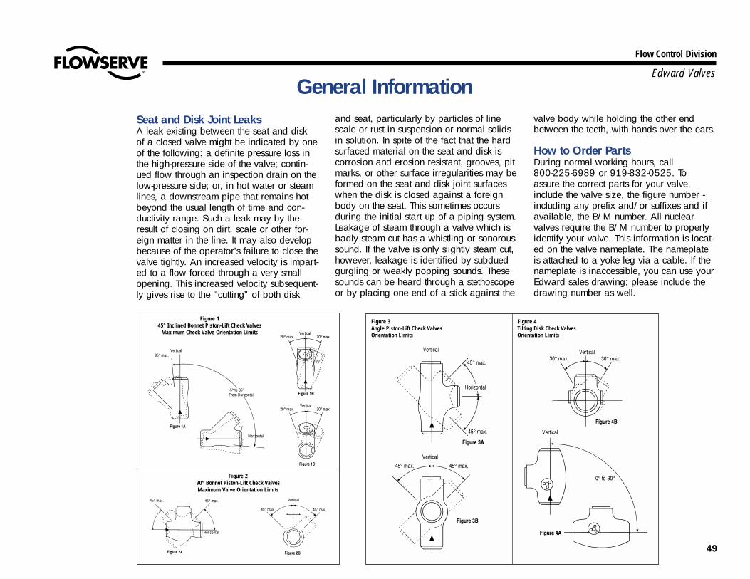
49
Flow Control Division
Edward Valves
Figure 290° Bonnet Piston-Lift Check ValvesMaximum Valve Orientation Limits
Figure 1 45° Inclined Bonnet Piston-Lift Check Valves
Maximum Check Valve Orientation Limits
Figure 3Angle Piston-Lift Check ValvesOrientation Limits
Figure 4Tilting Disk Check Valves Orientation Limits
General InformationSeat and Disk Joint LeaksA leak existing between the seat and diskof a closed valve might be indicated by oneof the following: a definite pressure loss inthe high-pressure side of the valve; contin-ued flow through an inspection drain on thelow-pressure side; or, in hot water or steamlines, a downstream pipe that remains hotbeyond the usual length of time and con-ductivity range. Such a leak may by theresult of closing on dirt, scale or other for-eign matter in the line. It may also developbecause of the operator’s failure to close thevalve tightly. An increased velocity is impart-ed to a flow forced through a very smallopening. This increased velocity subsequent-ly gives rise to the “cutting” of both disk
and seat, particularly by particles of linescale or rust in suspension or normal solidsin solution. In spite of the fact that the hardsurfaced material on the seat and disk iscorrosion and erosion resistant, grooves, pitmarks, or other surface irregularities may beformed on the seat and disk joint surfaceswhen the disk is closed against a foreignbody on the seat. This sometimes occursduring the initial start up of a piping system.Leakage of steam through a valve which isbadly steam cut has a whistling or sonoroussound. If the valve is only slightly steam cut,however, leakage is identified by subduedgurgling or weakly popping sounds. Thesesounds can be heard through a stethoscopeor by placing one end of a stick against the
valve body while holding the other endbetween the teeth, with hands over the ears.
How to Order PartsDuring normal working hours, call 800-225-6989 or 919-832-0525. Toassure the correct parts for your valve,include the valve size, the figure number -including any prefix and/or suffixes and ifavailable, the B/M number. All nuclearvalves require the B/M number to properlyidentify your valve. This information is locat-ed on the valve nameplate. The nameplateis attached to a yoke leg via a cable. If thenameplate is inaccessible, you can use yourEdward sales drawing; please include thedrawing number as well.

50
Flow Control Division
Edward ValvesSupplementary Repair Information
In analyzing valve trouble in the field, it isimportant to consider the following factors:
1. Size of the valve.2. Figure number of the valve.3. Type of service (water, oil, gas,
superheated steam, etc.)4. Operating pressures and
temperature.5. Direction of flow through stop valves
(inlet pressure above the disk orbelow the disk).
6. Rate of flow through the valve (lbs.per hour or gallons per minute).
7. What pressure temperature or flow rateat which the reported trouble occurs.
8. Pressure drop across the valve.
Information RequestIf the maintenance problem looks particu-larly difficult, it is suggested that you con-tact your local Edward Valves representa-tive. They are familiar with these mainte-nance instructions and has a variety ofengineering data sheets. In all communica-tions with your local representative con-cerning service difficulties, mention thevalve size, figure number, registration num-ber (if one is given) and as many of theeight conditions listed above as possible.Some of this information is found on thenameplate fastened to the valve yoke.
Ordering PartsAll requests for replacement parts for caststeel valves should be forwarded to theEdward business unit in Raleigh, NorthCarolina. Specify shipment requirements(Air Express, Area Express, etc.)
Edward Valves designs and manufactures allvalves for 40 years’ service. That means not justbuilding a reliable product, but one that is easyto maintain and service. It also means providinga team of experienced, dedicated professionalsto keep your Edward valves operating at peakperformance. Something we have been doingsince 1904.

Flow Control Division
Edward Valves
Flowserve Corporation has established industry leadership in the design and manufacture of its products. When properly selected, this Flowserve product is designed to perform its intended function safely during its useful life. How-ever, the purchaser or user of Flowserve products should be aware that Flowserve products might be used in numerous applications under a wide variety of industrial service conditions. Although Flowserve can (and often does) pro-vide general guidelines, it cannot provide specific data and warnings for all possible applications. The purchaser/user must therefore assume the ultimate responsibility for the proper sizing and selection, installation, operation, andmaintenance of Flowserve products. The purchaser/user should read and understand the Installation Operation Maintenance (IOM) instructions included with the product, and train its employees and contractors in the safe use ofFlowserve products in connection with the specific application.
While the information and specifications contained in this literature are believed to be accurate, they are supplied for informative purposes only and should not be considered certified or as a guarantee of satisfactory results byreliance thereon. Nothing contained herein is to be construed as a warranty or guarantee, express or implied, regarding any matter with respect to this product. Because Flowserve is continually improving and upgrading its productdesign, the specifications, dimensions and information contained herein are subject to change without notice. Should any question arise concerning these provisions, the purchaser/user should contact Flowserve Corporation at anyone of its worldwide operations or offices.
© 2003 Flowserve Corporation, Irving, Texas, USA. Flowserve and Edward Valves are registered trademarks of Flowserve Corporation. V-377 R4 3/03 Printed in USA
FLOWSERVE CORPORATIONFLOW CONTROL DIVISIONEdward Valves1900 South Saunders StreetRaleigh, NC 27603 USA
Toll- Free Telephone Service(U. S. and Canada)Day: 1-800-225-6989
After Hours Customer Service1-800-543-3927
US Sales OfficesPhone: 919-832-0525Facsimile: 919-831-3369Facsimile: 919-831-3376
Visit Our Websitewww.edwardvalves.com
For more information about Flowserve Corporation, contact www.flowserve.com or call USA 1-800-225-6989.