edward valves - inland valve corporationinlandvalve.com/wp-content/uploads/2015/10/edward...1. stem...
TRANSCRIPT
Edward ValvesEdward Univalve Operation
and Maintenance ManualV-370 R3

3
Flow Control Division
Edward ValvesTable of Contents
Three Tools For Faster In-Line Repairs of Edward Univalves Edward Customer ServiceConsult your Edwardfactory inside salesrepresentative for information on obtain-ing repair tools. As always, field salesand service person-nel are available toassist with mainte-nance and repairsinvolving Edwardvalves. And they arebacked up by factory -trained spe-cialists to lend addi-tional assistancewhenever needed. An improved low-maintenanceUnivalve design...tools for fast in-linerepairs...and reliableEdward service!
Edward Univalves aren’t likely to require any maintenance or repair workuntil they’ve been in services for quite a few years. But sooner or later –depending on the nature of the fluids,frequency of operation and time in service –Univalve seats and disks may need to berepaired.For fast, one-man, in-line repair of EdwardUnivalves, three lightweight, portable tools areavailable: Seat Refinishing Tool, BonnetTorquing Collar and the Seal Weld CuttingMachine. Following are photographs anddescriptions of these tools.The Seat Refinishing Tool has a self centeringhead of multiple tungsten carbide cutters on aspindle which is hand operated with a speedwrench for complete seat refinishing. Lappingor other finishing work is not required to produce refinished seats. Seat damage, such as that produced by foreign materials in the line fluids can berepaired quickly.The Bonnet Torquing Collar is essentially atorque wrench adapter that is used to removeand reassemble the bonnet of an unwelded Univalve.The tool facilitates reassembly of the bonnetwith the required torque correctly applied toensure that the graphitic body-bonnet gasket isproperly loaded to establish a leak-tight seal.The tool may also be used to assemble and disassemble seal-welded valves.The Seal Weld Cutting Machine has the abilityto cut both fillet and canopy welds. By remov-ing the handwheel and yoke, then installingthe machine, seal welds can be cut leaving asuitable weld prep. The machine is operatedby one person and uses conventional plant air.
Three Tools for Faster In-Line Repairs of Edward Univalves .................................2
Exploded View ............................................3Disassembling the Univalve ........................4-6Servicing Edward Univalve Stop Valves
& Stop-Check Valves..................................7Servicing Univalve Check Valves ...................8Alternate Weld-Cutting
Methods for Univalves ...............................9Univalve Maintenance Tools ...................10-14Reassembly Of The Univalve...................15-19
Reassembly of Unwelded Bonnet Univalves ..................................15
Reassembly of Welded Bonnet Univalves ...16Replacing The Seal Weld on
A105 & F22 Univalves ............................20Replacing The Seal Weld on
F316 & F347 Univalves...........................21Operational Recommendations ....................22General Information ..............................24-25
CHARTSValves With No Prefix In
Figure Numbers .................................11-12Valves With “B” Prefix Figure Numbers ........13Valves With “C” & “D” Prefix
Figure Numbers ......................................14Unwelded Univalve Bonnet Gasket Torques ...17Welded Univalve Bonnet Torques .................18Torque Range for Packing Gland Bolts..........19Minimum torque for Closing Valves –
Ft Lbs on Main Seat.................................22Impactor Handle/Handwheel
Performance Chart ..................................23
Seat Refinishing Tool
Bonnet Torquing Collar
Seal Weld Cutting Machine

1. Stem Nut2. Washer3. Handwheel4. Stem/Disk Assembly5. Locking Collar
(unwelded bonnet valves only)6. Body7. Yoke Nut8. Graphitic Gasket*
(unwelded bonnet valves only)9. Bonnet
10. Packing11. Yoke Bolt12. Gland13. Yoke 14. Gland Adjusting Screws15. Cap Plugs16. Yoke Bushing
1.
2.
3.
4.
5.
6.
7.
16.
15.
14.
13.
12.
11.
10.
9.
8.
*Class 4500 welded bonnet Univalves have a bonnet insert and graphic gasket seal ring as shown on page 17.
(shown turned 90°)
4
Flow Control Division
Edward ValvesExploded View

5
Flow Control Division
Edward Valves
Disassembling The Univalve
STEP 1 Double-check to make sure thatline pressure has been relieved before dis-assembling the valve.
STEP 2 The valve should be in the openposition and not against the body seat orbackseat.
STEP 3 If the valve is manually operated,remove the lock nut that attaches the hand-wheel or impactor handle to the valvestem. Remove the handwheel or handle. Ifthe valve is motor operated, remove theactuator from the valve stem.
STEP 4 Loosen the two gland adjustmentscrews that rest against the packing glandby threading them higher into the yoke. Ahex allen wrench inserted into the top ofthe gland screw thru the holes in the top ofthe yoke (remove the dirt protectors first)will speed this up.
STEP 5 Loosen the yoke clamp bolt andnut. It is not necessary to completelyremove them.
STEP 6 Remove the yoke assembly byunscrewing it from the bonnet. A gentle tapwith a hammer might be necessary beforethe yoke will unscrew away from the bon-net. You may find it easier to remove theyoke by placing the handwheel on the stemto prevent the stem from rotating. When theyoke is even with the top of the stem, andyou can no longer use the valve handwheelor handle you will need to grasp the lowerportion of the stem between the yoke andbonnet. If the yoke is turning freely, a clothmay be adequate to hold the stem. If this isnot adequate, a strap wrench that will notdamage the stem surface should be used. Ifonly the packing is to be replaced, this cannow be easily done with no further disas-sembly of the Univalve. See Step 14.
CAUTIONLine Pressure
must be relieved beforedisassembling
the valve.
6
Flow Control Division
Edward ValvesDisassembling The Univalve (cont.)
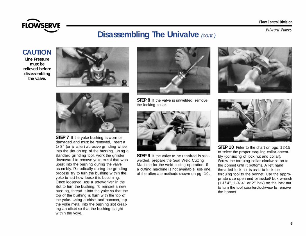
STEP 7 If the yoke bushing is worn ordamaged and must be removed, insert a1/8” (or smaller) abrasive grinding wheelinto the slot on top of the bushing. Using astandard grinding tool, work the grinderdownward to remove yoke metal that wasupset into the bushing during the valveassembly. Periodically during the grindingprocess, try to turn the bushing within theyoke to test how loose it is becoming.Once loosened, use a screwdriver in theslot to turn the bushing. To reinsert a newbushing, thread it into the yoke so that thetop of the bushing is flush with the top ofthe yoke. Using a chisel and hammer, tapthe yoke metal into the bushing slot creat-ing an offset so that the bushing is tightwithin the yoke.
STEP 8 If the valve is unwelded, removethe locking collar.
STEP 9 If the valve to be repaired is seal-welded, prepare the Seal Weld CuttingMachine for the weld cutting operation. Ifa cutting machine is not available, use oneof the alternate methods shown on pg. 10.
STEP 10 Refer to the chart on pgs. 12-15to select the proper torquing collar assem-bly (consisting of lock nut and collar).Screw the torquing collar clockwise on tothe bonnet until it bottoms. A left handthreaded lock nut is used to lock thetorquing tool to the bonnet. Use the appro-priate size open end or socket/box wrench(1-1/4”, 1-3/4” or 2” hex) on the lock nutto turn the tool counterclockwise to removethe bonnet.
CAUTIONLine Pressure
must be relieved beforedisassembling
the valve.

7
Flow Control Division
Edward ValvesDisassembling The Univalve (cont.)
STEP 11 Remove the valve bonnet-stem-disk assembly if the valve being repaired isa stop valve (figure XXX2X). The disk in astop-check vaIve (figure XXX6X and thebonnet insert in welded Class 4500 vaIves(figure 961XX) may be removed by form-ing a short piece soft wire into the shapeof an L and lifting up in the disk bore.
STEP 12 Remove the stem from thebonnet. It may be necessary to rotate stemthrough the packing before it can beremoved.
STEP 13 If the valve is unwelded, thegraphitic gasket must be replaced. Do soby removing it from the valve body buttake care not to damage machinedsurfaces.
STEP 14 Using a packing tool, removethe old packing. Stainless steel Univalvesare equipped with a metal junk ring in thebottom of the packing chamber (see pg.19 for repacking instructions).
CAUTIONLine Pressure
must be relieved beforedisassembling
the valve.
8
Flow Control Division
Edward Valves
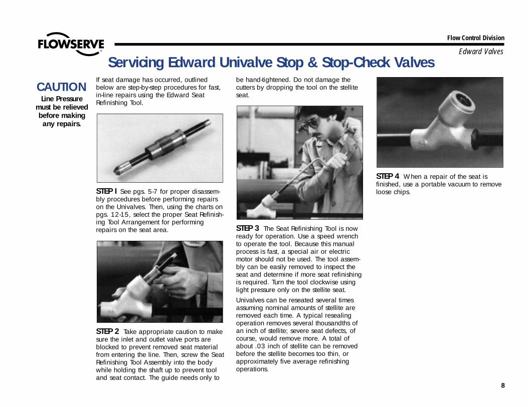
If seat damage has occurred, outlinedbelow are step-by-step procedures for fast,in-line repairs using the Edward SeatRefinishing Tool.
STEP I See pgs. 5-7 for proper disassem-bly procedures before performing repairson the Univalves. Then, using the charts onpgs. 12-15, select the proper Seat Refinish-ing Tool Arrangement for performingrepairs on the seat area.
STEP 2 Take appropriate caution to makesure the inlet and outlet valve ports areblocked to prevent removed seat materialfrom entering the line. Then, screw the SeatRefinishing Tool Assembly into the bodywhile holding the shaft up to prevent tooland seat contact. The guide needs only to
be hand-tightened. Do not damage thecutters by dropping the tool on the stelliteseat.
STEP 3 The Seat Refinishing Tool is nowready for operation. Use a speed wrenchto operate the tool. Because this manualprocess is fast, a special air or electricmotor should not be used. The tool assem-bly can be easily removed to inspect theseat and determine if more seat refinishingis required. Turn the tool clockwise usinglight pressure only on the stellite seat.Univalves can be reseated several timesassuming nominal amounts of stellite areremoved each time. A typical resealingoperation removes several thousandths ofan inch of stellite; severe seat defects, ofcourse, would remove more. A total ofabout .03 inch of stellite can be removedbefore the stellite becomes too thin, orapproximately five average refinishingoperations.
STEP 4 When a repair of the seat isfinished, use a portable vacuum to removeloose chips.
Servicing Edward Univalve Stop & Stop-Check Valves
CAUTIONLine Pressure
must be relieved before makingany repairs.
9
Flow Control Division
Edward ValvesServicing Edward Univalve Check Valves
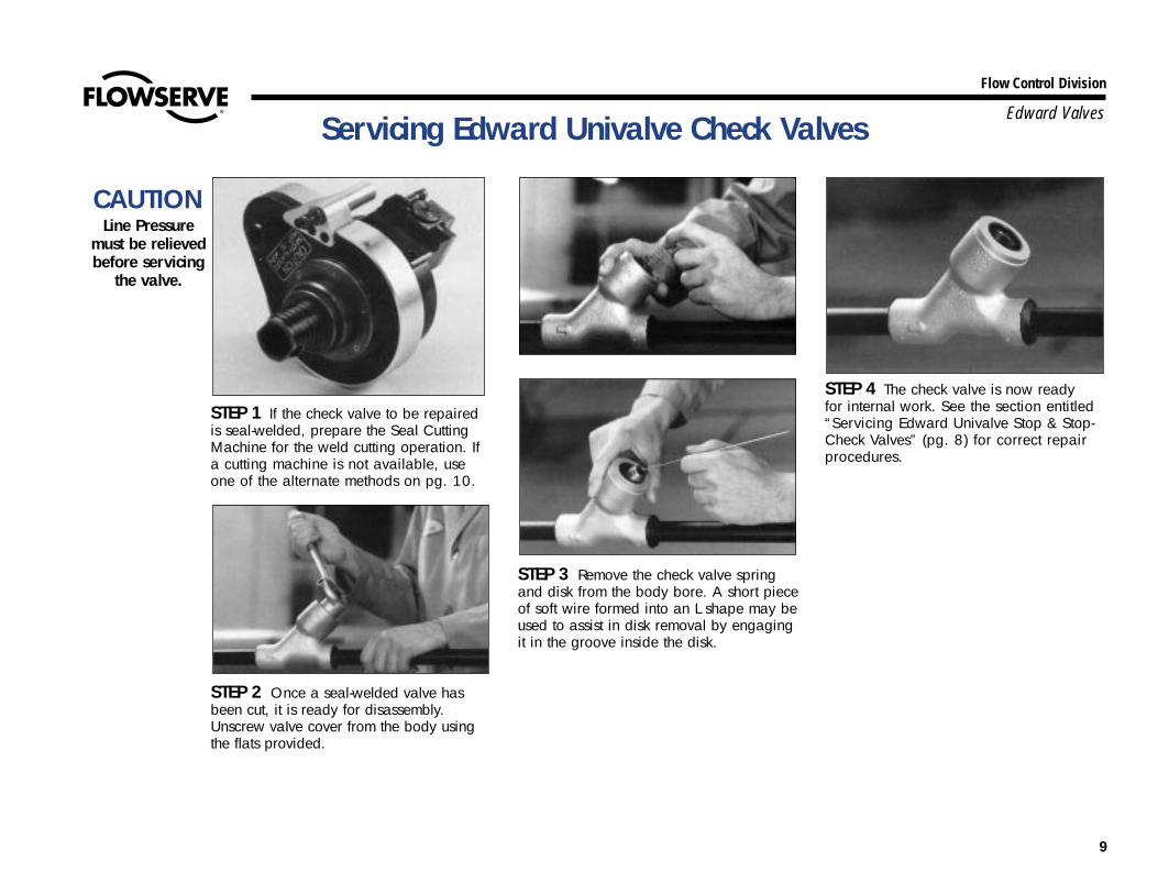
STEP 1 If the check valve to be repairedis seal-welded, prepare the Seal CuttingMachine for the weld cutting operation. Ifa cutting machine is not available, useone of the alternate methods on pg. 10.
STEP 2 Once a seal-welded valve hasbeen cut, it is ready for disassembly.Unscrew vaIve cover from the body usingthe flats provided.
STEP 3 Remove the check valve springand disk from the body bore. A short pieceof soft wire formed into an L shape may beused to assist in disk removal by engagingit in the groove inside the disk.
STEP 4 The check valve is now ready for internal work. See the section entitled“Servicing Edward Univalve Stop & Stop-Check Valves” (pg. 8) for correct repairprocedures.
CAUTIONLine Pressure
must be relieved before servicing
the valve.
10
Flow Control Division
Edward Valves
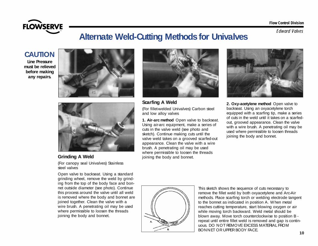
Grinding A Weld(For canopy seal Univalves) Stainless steel valves Open valve to backseat. Using a standardgrinding wheel, remove the weld by grind-ing from the top of the body face and bon-net outside diameter (see photo). Continuethis process around the valve until all weldis removed where the body and bonnet arejoined together. Clean the valve with awire brush. A penetrating oil may be usedwhere permissible to loosen the threadsjoining the body and bonnet.
Scarfing A Weld(For fillet-welded Univalves) Carbon steeland low alloy valves
1. Air-arc method Open valve to backseat.Using air-arc equipment, make a series ofcuts in the valve weld (see photo andsketch). Continue making cuts until thevalve weld takes on a grooved scarfed-outappearance. Clean the valve with a wirebrush. A penetrating oil may be usedwhere permissible to loosen the threadsjoining the body and bonnet.
2. Oxy-acetylene method Open valve tobackseat. Using an oxyacetylene torchequipped with a scarfing tip, make a seriesof cuts in the weld until it takes on a scarfed-out, grooved appearance. Clean the valvewith a wire brush. A penetrating oil may beused where permissible to loosen threadsjoining the body and bonnet.
Alternate Weld-Cutting Methods for Univalves
CAUTIONLine Pressure
must be relieved before makingany repairs.
This sketch shows the sequence of cuts necessary toremove the fillet weld by both oxyacetylene and Arc-Airmethods. Place scarfing torch or welding electrode tangentto the bonnet as indicated in position A. When metalreaches cutting temperature, start blowing oxygen or airwhile moving torch backward. Weld metal should beblown away. Move torch counterclockwise to position B -repeat until entire fillet weld is removed and gap is contin-uous. DO NOT REMOVE EXCESS MATERIAL FROMBONNET OR UPPER BODY FACE.
A.
B.

11
Flow Control Division
Edward Valves
Seat Refinishing Tool Assembly Bonnet Torquing Collar Assembly
Univalve Maintenance Tools

12
Flow Control Division
Edward Valves
Valves With No Prefix In Figure NumbersTOOL GUIDE GUIDE BONNET NO. OF CHECK VALVE
FIGURE HEAD BUSHING BUSHING FOR TORQUING REPLACEMENT CUTTERS ADAPTER TORQUESIZE NUMBER1,6 ASSEMBLY FOR CARBON STAINLESS COLLAR CUTTERS2 ON HEAD ASSEMBLY4 GROUP5
STEEL VALVES3 STEEL VALVES ASSEMBLY ASSEMBLY
1/2 361XX 876111 875920 875929 876744 —- —- 876678 N/A3/4 361XX 876111 875920 875929 876744 —- —- 876678 N/A1 361XX 876112 975920 875929 876745 —- —- 876679 N/A
1-1/4 361XX 876113 875922 875930 876746 876703 3 876680 B1-1/2 361XX 876114 875921 875931 876746 876703 5 876680 A
2 361XX 876115 875924 875933 876747 876703 5 876681 D2-1/2 361XX 876116 875926 875917 876748 876703 7 876683 E
3 361XX 876116 875926 875917 876748 876703 7 876683 E4 361XX 876116 875927 875936 876750 876703 7 876684 E
1/2 362XX 876111 875920 875929 876744 —- —- 876678 N/A3/4 362XX 876111 875920 875929 876744 —- —- 876678 N/A1 362XX 876111 875920 875929 876744 —- —- 876679 N/A
1-1/4 362XX 876113 875922 875930 876746 876703 3 876680 B1-1/2 362XX 876113 875922 875930 876746 876703 3 876680 B
2 362XX 876114 875923 875918 876746 876703 5 876681 A2-1/2 362XX 876115 875925 875934 876749 876703 5 876682 D
3 362XX 876115 875925 875934 876749 876703 5 876682 D4 362XX 876116 875927 875936 876750 876703 7 876684 E
1/2 661XX 876111 875920 875929 876744 — —- 876678 N/A3/4 661XX 876111 875920 875929 876744 —- —- 876678 N/A
1 661XX 876112 875920 875929 876745 —- —- 876679 N/A1-1/4 661XX 876113 875922 875930 876746 876703 3 876680 B1-1/2 661XX 876113 875922 875930 876746 876703 3 876680 B
2 661XX 876115 875925 875934 876749 876703 5 876682 D2-1/2 661XX 876116 875927 875936 876750 876703 7 876684 E
3 661XX 876116 875927 875936 876750 876703 7 876684 E4 661XX 876116 875927 875936 876750 876703 7 876684 E
Notes:1. First three numbers indicate pressure class and bonnet seal, remaining two
numbers denote valve type and end configuration, which have no effect on toolselection.
2. Where dashes are indicated, cutters cannot be replaced.3. Low alloy steel valves use same tools as carbon steel valves.4. Required for using bonnet torquing collar and seal weld cutting machine on
check valves.
5. To be used to determine the number of impacts required to close valves withimpactor handles/handwheels (see page 23). “N/A” indicates that the valve(s)have standard handwheel (non-impactor).
6. Four digit figure number Univalves use different maintenance tools. Please consultyour Edward Valves sales representative.
Univalve Maintenance Tools

13
Flow Control Division
Edward ValvesUnivalve Maintenance Tools (cont.)
Valves With No Prefix In Figure Numbers
Notes:1. First three numbers indicate pressure class and bonnet seal, remaining two num-
bers denote valve type and end configuration, which have no effect on toolselection.
2. Where dashes are indicated, cutters cannot be replaced.3. Low alloy steel valves use same tools as carbon steel valves.4. Required for using bonnet torquing collar and seal weld cutting machine on
check valves.
5. To be used to determine the number of impacts required to close valves withimpactor handles/handwheels (see page 23). “N/A” indicates that the valve(s)have standard handwheel (non-impactor).
6. Four digit figure number Univalves use different maintenance tools. Please con-sult your Edward Valves sales representative.
TOOL GUIDE GUIDE BONNET NO. OF CHECK VALVEFIGURE HEAD BUSHING BUSHING FOR TORQUING REPLACEMENT CUTTERS ADAPTER TORQUE
SIZE NUMBER1,6 ASSEMBLY FOR CARBON STAINLESS COLLAR CUTTERS2 ON HEAD ASSEMBLY4 GROUP5
STEEL VALVES3 STEEL VALVES ASSEMBLY ASSEMBLY
1/2 662XX 876111 875920 875929 876744 —- —- 876678 N/A3/4 662XX 876111 875920 875929 876744 —- —- 876678 N/A1 662XX 876111 975920 875929 876744 —- —- 876679 N/A
1-1/4 662XX 876113 875922 875930 876746 876703 3 876680 B1-1/2 662XX 876113 875922 875930 876746 876703 3 876680 B
2 662XX 876115 875925 875934 876749 876703 5 876682 D2-1/2 662XX 876116 875927 875936 876750 876703 7 876684 E
3 662XX 876116 875927 875936 876750 876703 7 876684 E4 662XX 876116 875927 875936 876750 876703 7 876684 E
1/2 961XX 876112 876772 876773 876751 —- —- 876762 N/A3/4 961XX 876112 876772 876773 876751 —- —- 876762 N/A1 961XX 876112 876772 876773 876751 —- —- 876762 N/A
1-1/4 961XX 876112 876722 876773 876751 —- —- 876762 N/A1-1/2 961XX 876112 876772 876773 876751 —- —- 876762 N/A
2 961XX 876115 875925 875934 876752 876703 5 876763 C2-1/2 961XX 876115 875925 875934 876752 876703 5 876763 C
3 961XX 876115 875925 875934 876752 876703 5 876763 C4 961XX 876115 875925 875934 876752 876703 5 876763 C
1/2 962XX 876112 876772 876773 876751 —- —- 876762 N/A3/4 962XX 876112 876772 876773 876751 —- —- 876762 N/A1 962XX 876112 876772 876773 876751 —- —- 876762 N/A
1-1/4 962XX 876112 876772 876773 876751 —- —- 876762 N/A1-1/2 962XX 876112 876772 876773 876751 —- —- 876762 N/A
2 962XX 876115 875925 875934 876752 876703 5 876763 C2-1/2 962XX 876115 875925 875934 876752 876703 5 876763 C
3 962XX 876115 875925 875934 876752 876703 5 876763 C4 962XX 876115 875925 875934 876752 876703 5 876763 C

14
Flow Control Division
Edward ValvesUnivalve Maintenance Tools (cont.)
TOOL GUIDE GUIDE BONNET NO. OF CHECK VALVEFIGURE HEAD BUSHING BUSHING FOR TORQUING REPLACEMENT CUTTERS ADAPTER TORQUE
SIZE NUMBER1,6 ASSEMBLY FOR CARBON STAINLESS COLLAR CUTTERS2 ON HEAD ASSEMBLY GROUP5
STEEL VALVES3 STEEL VALVES ASSEMBLY ASSEMBLY4
1/2 B36XXX 876112 499563 499564 876745 —- —- 166933 N/A3/4 B36XXX 876112 499563 499564 876745 —- —- 166933 N/A1 B36XXX 876112 499563 499564 876745 —- —- 166933 N/A
1-1/4 B36XXX 876114 875923 494228 876746 876703 5 166934 B1-1/2 B36XXX 876114 875923 494228 876746 876703 5 166934 B
2 B36XXX 876115 875925 875934 876749 876703 5 166935 D2-1/2 B36XXX 876116 875927 875936 876749 876703 7 166936 E
3 B36XXX 876116 875927 875936 876749 876703 7 166936 E4 B36XXX 876116 875927 875936 876748 876703 7 166939 E
1/2 B66XXX 876112 499563 499564 876745 —- —- 166933 N/A3/4 B66XYX 876112 499563 499564 876745 —- —- 166933 N/A1 B66XXX 876112 499563 499564 876745 —- —- 166933 N/A
1-1/4 B66XXX 876113 875922 875930 876746 876703 3 166934 A1-1/2 B66XXX 876113 875922 875930 876746 876703 3 166934 A
2 B66XXX 876115 875925 875934 876749 876703 5 166935 D2-1/2 B66XYX 876116 875927 875936 876748 876703 7 166939 E
3 B66XXX 876116 875927 875936 876748 876703 7 166939 E4 B66XXX 876116 875927 875936 876748 876703 7 166939 E
1/2 B96XXX 876112 876772 876773 876746 —- —- 168554 N/A3/4 B96XXX 876112 876772 876773 876746 —- —- 168554 N/A
1 B96XXX 876112 876772 876773 876746 —- —- 168554 N/A1-1/4 B96XXX 876112 876772 876773 876746 —- —- 168554 N/A1-1/2 B96XXX 876112 876772 876773 876746 —- —- 168554 N/A
2 B96XXX 876115 875925 875934 876748 876703 5 876683 C2-1/2 B96XXX 876115 875925 875934 876748 876703 5 876683 C
3 B96XXX 876115 875928 875934 876748 876703 5 876683 C4 B96XXX 876115 875925 875934 876748 876703 5 876683 C
Valves With “B” Prefix Figure Numbers
Notes:1. First three numbers indicate pressure class and bonnet seal, remaining two num-
bers denote valve type and end configuration, which have no effect on toolselection.
2. Where dashes are indicated, cutters cannot be replaced.3. Low alloy steel valves use same tools as carbon steel valves.4. Required for using bonnet torquing collar and seal weld cutting machine on
check valves.
5. To be used to determine the number of impacts required to close valves withimpactor handles/handwheels (see page 23). “N/A” indicates that the valve(s)have standard handwheel (non-impactor).
6. Four digit figure number Univalves use different maintenance tools. Please con-sult your Edward Valves sales representative.

15
Flow Control Division
Edward ValvesUnivalve Maintenance Tools (cont.)
TOOL GUIDE GUIDE BONNET NO. OF CHECK VALVEFIGURE HEAD BUSHING BUSHING FOR TORQUING REPLACEMENT CUTTERS ADAPTER TORQUE
SIZE NUMBER1,6 ASSEMBLY FOR CARBON STAINLESS COLLAR CUTTERS2 ON HEAD ASSEMBLY GROUP5
STEEL VALVES3 STEEL VALVES ASSEMBLY ASSEMBLY4
1/2 X36XXX 876112 499564 499564 876745 —- —- 166933 N/A3/4 X36XXX 876112 499564 499564 876745 —- —- 166933 N/A1 X36XXX 876112 499564 499564 876745 —- —- 166933 N/A
1-1/4 X36XXX 876114 494228 494228 876746 876703 5 166934 B1-1/2 X36XXX 876114 494228 494228 876746 876703 5 166934 B
2 X36XXX 876115 875934 875934 876749 876703 5 166935 D2-1/2 X36XXX 876116 875936 875936 876749 876703 7 166936 E
3 X36XXX 876116 875936 875936 876749 876703 7 166936 E4 X36XXX 876116 875936 875936 876748 876703 7 166939 E
1/2 X66XXX 876112 499564 499564 876745 —- —- 166933 N/A3/4 X66XXX 876112 499564 499564 876745 —- —- 166933 N/A1 X66XXX 876112 499564 499564 876745 —- —- 166933 N/A
1-1/4 X66XXX 876113 875930 875930 876746 876703 3 166934 A1-1/2 X66XXX 876113 875930 875930 876746 876703 3 166934 A
2 X66XXX 876115 875934 875934 876749 876703 5 166935 D2-1/2 X66XXX 876116 875936 875936 876748 876703 7 166939 E
3 X66XXX 876116 875936 875936 876748 876703 7 166939 E4 X66XXX 876116 875936 875936 876748 876703 7 166939 E
1/2 X96XXX 876112 876773 876773 876746 —- —- 168554 N/A3/4 X96XXX 876112 876773 876773 876746 —- —- 168554 N/A1 X96XXX 876112 876773 876773 876746 —- —- 168554 N/A
1-1/4 X96XXX 876112 876773 876773 876746 —- —- 168554 N/A1-1/2 X96XXX 876112 876773 876773 876746 —- —- 168554 N/A
2 X96XXX 876115 875934 875934 876748 876703 5 876683 C2-1/2 X96XXX 876115 875934 875934 876748 876703 5 876683 C
3 X96XXX 876115 875934 875934 876748 876703 5 876683 C4 X96XXX 876115 875934 875934 876748 876703 5 876683 C
Valves With “C” & “D” Prefix Figure Numbers*
Notes:1. First three numbers indicate pressure class and bonnet seal, remaining two num-
bers denote valve type and end configuration, which have no effect on toolselection.
2. Where dashes are indicated, cutters cannot be replaced.3. Low alloy steel valves use same tools as carbon steel valves.4. Required for using bonnet torquing collar and seal weld cutting machine on
check valves.
5. To be used to determine the number of impacts required to close valves withimpactor handles/handwheels (see page 23). “N/A” indicates that the valve(s)have standard handwheel (non-impactor).
6. Four digit figure number Univalves use different maintenance tools. Please con-sult your Edward sales representative.
*Prefix examples: X36220 = C36220 or D36220.

16
Flow Control Division
Edward Valves
GENERAL: Be sure all parts are clean ofdirt, rust or scale.
• Always install a new stem-disk assem-bly into the bonnet if the one is dam-aged, e.g., the disk seat damaged orstem scratched, worn or pitted. Makesure all dirt is removed from oldstems.
• Apply a light coating of a good high-temperature lubricant to the bonnet-body threads, such as Bostik Never-Seez™–Regular Grade; stainless Uni-valves should use Nickel SpecialNuclear Grade. Do not use excessiveamounts and keep it off the gasketseal faces of unwelded Univalves.
• Next install a new graphitic gasketseal ring – it should always bereplaced – by slipping it onto thebonnet and placing it snugly againstthe off-set. A light film of oil (notNever-Seez™) helps hold it in place.
• Slip the locking collar over the bonnetfrom the body end, with the lugtowards the body. Install the capscrewand nut on the collar, but do nottighten.*
• Next carefully screw the bonnet and -stem-disk assembly into the body, mak-ing certain the disk is off the bodyseat (valve is open). Using the BonnetTorquing Collar assembly, tighten thethreads to the torque shown forunwelded bonnet Univalves.THIS IS VERY IMPORTANT FORUNWELDED BONNET UNIVALVES.
• Verify that the bonnet shoulder doesnot bottom out on the body.
• Rotate the locking collar counter--clockwise so the lug is against one ofthe body lugs. Tighten nut to thetorque value for the yoke bolts asshown in the next column.
• Install the packing if the original is tobe replaced. See “PackingInstallation,” pg.19.
• Making sure the stem is clean, applya light coat of extreme pressuregrease, such as American Oil RyconEP-2 or equivalent on the threads.Screw the yoke onto the stem, then onto the bonnet turning it down snuglyagainst the bonnet shoulder. Lubricateand then tighten the yoke bolt asfollows:
3/8 dia.bolt – 16/20 Ft-lbs25/30 N-M
7/16 dia. bolt – 30/35 Ft-lbs45/50 N-M
• Tighten the gland bolts – IMPORTANT– per “Torque Range For PackingGland Bolts,” pg. 20.
• Install the handwheel or actuator. Forsafety reasons, make sure the self-locking stem nut is tight on handwheelvalves.
Reassembly Of The UnivalveREASSEMBLY OF UNWELDED BONNET UNIVALVES
*NOTE: Univalves with “B” prefix or no prefix have a different type of locking collarwhich is installed after the bonnet has been tightened into the body.

17
Flow Control Division
Edward Valves
GENERAL: Be sure all parts are clean ofdirt, rust or scale.
• Always install a new stem-disk assem-bly into the bonnet if the old one isdamaged, e.g., the disk seat is dam-aged or stem scratched/worn or pit-ted. Make sure all dirt is removedfrom old stems.
• Class 4500 welded bonnet Univalves(only) should have both the bonnetinsert and graphitic gasket seal ringreplaced. Do this by removing thestem-disk assembly from the bonnet,placing the new bonnet insert andgraphitic gasket seal ring over thestem, then installing the stem back intothe bonnet.
• Apply a light coating of a good high-temperature lubricant to the bonnet-body threads, such as Bostik Never-Seez™ Regular Grade; stainless Uni-valves should use Nickel SpecialNuclear Grade. Do not use excessiveamounts.
• Next carefully screw the bonnet andstem-disk assembly into the body, mak-ing certain the disk is off the bodyseat (valve is open). Apply a nominaltorque as specified on pg. 19 forwelded bonnet Univalves.
• Seal weld the bonnet, refer to pg. 21.• Install the packing if the original is to
be replaced. See “Packing Installa-tion,” pg. 19.
• Making sure the stem is clean, applya light coat of extreme pressuregrease, such as American Oil RyconEP-2 or equivalent, on the threads.Screw the yoke onto the stem, then onto the bonnet turning it down snuglyagainst the bonnet shoulder. Lubricateand then tighten the yoke bolt as fol-lows
3/8 dia.bolt – 16/20 Ft-lbs25/30 N-M
7/16 dia. bolt – 30/35 Ft-lbs45/50 N-M
• Tighten the gland bolts – IMPORTANT– per “Torque Range For PackingGland Bolts,” pg. 20.
• Install the handwheel or actuator. Forsafety reasons, make sure the self-lock-ing stem nut is tight on handwheelvalves.
Reassembly Of The Univalve (cont.)
REASSEMBLYOF WELDEDBONNETUNIVALVES
18
Flow Control Division
Edward ValvesReassembly of The Univalve (cont.)
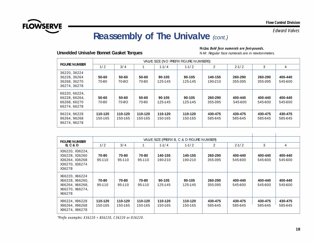
FIGURE NUMBER VALVE SIZE (PREFIX B, C & D FIGURE NUMBER)B, C & D 1/2 3/4 1 1-1/4 1-1/2 2 2-1/2 3 4
X36220, X36224,X36228, X36260 70-80 70-80 70-80 140-155 140-155 260-290 400-440 400-440 400-440X36264, X36268 95-110 95-110 95-110 190-210 190-210 355-395 545-600 545-600 545-600X36270, X36274X36278
X66220, X66224X66228, X66260, 70-80 70-80 70-80 90-105 90-105 260-290 400-440 400-440 400-440X66264, X66268, 95-110 95-110 95-110 125-145 125-145 355-395 545-600 545-600 545-600X66270, X66274,X66278
X96224, X96228 110-120 110-120 110-120 110-120 110-120 430-475 430-475 430-475 430-475X96264, X96268 150-165 150-165 150-165 150-165 150-165 585-645 585-645 585-645 585-645X96274, X96278
FIGURE NUMBERVALVE SIZE (NO PREFIX FIGURE NUMBERS)
1/2 3/4 1 1-1/4 1-1/2 2 2-1/2 3 4
36220, 3622436228, 36264 50-60 50-60 50-60 90-105 90-105 140-155 260-290 260-290 400-44036268, 36270 70-80 70-8O 70-80 125-145 125-145 190-210 355-395 355-395 545-60036274, 36278
66220, 66224,66228, 66264, 50-60 50-60 50-60 90-105 90-105 260-290 400-440 400-440 400-44066268, 66270 70-80 70-8O 70-80 125-145 125-145 355-395 545-600 545-600 545-60066274, 66278
96224, 96228 110-120 110-120 110-120 110-120 110-120 430-475 430-475 430-475 430-47596264, 96268 150-165 150-165 150-165 150-165 150-165 585-645 585-645 585-645 585-64596274, 96278
Ft-Lbs: Bold face numerals are feet-pounds.Unwelded Univalve Bonnet Gasket Torques N-M: Regular face numerals are in newton-meters.
*Prefix examples: X36220 = B36220, C36220 or D36220.

19
Flow Control Division
Edward Valves
GENERAL: Be sure all parts are clean ofdirt, rust or scale.
PACKING INSTALLATIONIf the Univalve packing was sealing welland has not been removed, it can bereused. However, if leaking, or if it hasbeen removed from the bonnet it should bereplaced. We recommend packing be pur-chased from Edward Valves to assure pack-ing with the proper density and corrosioninhibitors is always used.IMPORTANT: Long service life from moderngraphitic packing requires that adequatepreloads be applied when repacking.
• All parts should be clean and notscored or pitted, especially the stem.
• The stem, disk and bonnet should bein the valve prior to installing the newpacking.
• Position split packing with the ends ofadjacent rings rotated 90°.
• Standard packing:Top Ring: Braided Carbon
Fiber Ring. Note: Class 4500 valvesuse two (2) top rings.
Center Ring: Flexible Graphite ring.Bottom Ring: Same as top (Class
4500 has only one (1) ring on bottom).
• Clean and lubricate the gland screws.• Tamp the packing down by hand
using the gland.• IMPORTANT: Apply the recommended
torque to the gland bolts evenly with-out cocking the gland. See pg. 20 fortorques.
• Stroke the stem and then recheck thetorque on the gland bolts.
Reassembly of The Univalve (cont.)
FIGURE NUMBERVALVE SIZE
1/2 3/4 1 1-1/4 1-1/2 2 2-1/2 3 4
ALL 50 10070 135
Packing Chamber Schematic
Ft-Lbs: Bold face numerals are feet-pounds.Welded Univalve Bonnet Torques N-M: Regular face numerals are in newton-meters.

20
Flow Control Division
Edward ValvesReassembly of The Univalve (cont.)
Ft-Lbs: Bold face numerals are feet-pounds.Torque Range For Packing Gland Bolts N-M: Regular face numerals are in newton-meters.
FIGURE NUMBERVALVE SIZE (NO PREFIX FIGURE NUMBERS)
1/2 3/4 1 1-1/4 1-1/2 2 2-1/2 3 436120,36124, 8-13 8-13 10-15 19-24 18-23 23-28 26-31 26-31 37-4236128,36164, 11-18 11-18 14-20 26-33 24-31 31-38 35-42 35-42 50-573616836220,36224 8-13 8-13 8-13 19-24 19-24 18-23 27-32 27-32 37-4236228,36264, 11-18 11-18 11-18 26-33 26-33 24-31 37-43 37-43 50-573636866120,66124, 9-14 9-14 11-16 21-26 21-26 30-35 41-47 41-47 41-4766128,66164, 12-19 12-19 15-22 29-35 29-35 41-47 56-64 56-64 56-646616866220,66224, 9-14 9-14 9-14 21-26 21-26 30-35 41-47 41-47 41-4766228,66264, 12-19 12-19 12-19 29-35 29-35 41-47 56-64 56-64 56-646626896124,96128, 18-23 18-23 18-23 25-30 25-30 63-72 63-72 63-72 63-7296164,96168 24-31 24-31 24-31 34-41 34-41 85-98 85-98 85-98 85-9896224, 96228, 18-23 18-23 18-23 25-30 25-30 63-72 63-72 63-72 63-7296264, 96268 24-31 24-31 24-31 34-41 34-41 85-98 85-98 85-98 85-98
FIGURE NUMBER VALVE SIZE (PREFIX B, C & D FIGURE NUMBERS)B, C, & D* 1/2 3/4 1 1-1/4 1-1/2 2 2-1/2 3 4
X36120, X36124,X36128, X36160,X36164, X36168, 10-15 10-15 10-15 21-26 21-26 33-38 37-42 37-42 37-42X36220, X36224, 14-20 14-20 14-20 29-35 29-35 45-52 50-57 50-57 50-57X36228, X36264,X36268X66120, X66124,X66128, X66160,X66164, X66168, 13-18 13-18 13-18 21-26 21-26 38-43 41-47 41-47 41-47X66220, X66224 18-24 18-24 18-24 29-35 29-35 52-58 56-64 56-64 56-64X66228, X66264,X66268X96124, X96128,X96164, X96168, 22-27 22-27 22-27 22-27 22-27 63-72 63-72 63-72 63-72X96224, X96228, 30-37 30-37 30-37 30-37 30-37 85-98 85-98 85-98 85-98 X96264, X96268
*Prefix examples: X36220 = B36220, C36220 or D36220.

21
Flow Control Division
Edward ValvesReplacing The Seal Weld On A105 & F22 Univalves
Seal weld of A105 (Carbon) and F22 (Low-alloy) Univalves are made using a “Fillet” weld.
RE-WELDING• To allow welding gases to escape, do
not fully seat or fully backseat valve.• Weld surfaces shall be clean and dry.• Preheat to 300°F – 400°F.• Weld A105 Univalves with SFA 5.1
E7018 electrodes and F22 Univalveswith SFA 5.5 E9018-B3 electrodes.
• Deposit weld metal to meet dimen-sions shown in table at right.
UNIVALVE SIZE MIN. LEG MIN. THROAT MIN. PASSES
1-1/2 & smaller 3/16 1/8 2
2 (except Class 4500) 1/4 3/16 2
2 (Class 4500 & valves over 2) 3/8 1/4 2

22
Flow Control Division
Edward ValvesReplacing The Seal Weld On F316 & F347 Univalves
JOINT –• Seal welds of F316, F316L and F347
(Stainless Steel) Univalves are madeusing a “Canopy” weld.
• Univalves should be prepared for theJoint design shown below.
RE-WELDING –• To allow welding gases to escape, do
not fully seat or fully backseat thevalve.
• Weld surfaces shall be clean and dry.• Preheat to 70° – 150°F.• Maintain an interpass temperature of
350°F maximum.• Weld F316 Univalves using SFA 5.9
ER316L bare rod, F316L Univalvesusing SFA 5.9 ER308L bare rod andF347 Univalves using SFA 5.9 ER347bare rod.
• Deposit weld metal to meet dimen-sions shown in sketch below.

23
Flow Control Division
Edward Valves
Recommended Closing TorquesTo assure long seat life and seat tightness,it is very important to close the Univalvewith enough seat stress/stem load.
The torques in this table should be appliedwhen closing against the maximum (100°F)valve pressure. The impactor handle/hand-wheel performance chart on pg. 23 willachieve these stem loads.
Overtorquing can, on the other hand, damage seats and bend stems so torquesgreatly in excess of these should not beapplied.
Operational Recommendations
Minimum Torque For Closing Valves – Ft-Lbs On Main Seat(Do Not Apply This Load To Backseats).
Torques are for valves with stem packing tightened – see pages 19 and 20.
FIGURE NUMBERALL VALVES WITH FIVE DIGIT FIGURE NUMBERS
1/2 3/4 1 1-1/4 1-1/2 2 2-1/2 3 4
36120,36124.36128,36160 30 30 30 95 95 155 275 275 27536164,36168
36220,36224, 36228, 36260, 30 30 30 95 95 155 275 275 27536264,36268
66120,66124,66128,66160, 45 45 45 85 85 230 395 395 39566164,66168
66220,66224,66228,66260, 45 45 45 85 85 230 395 395 39566264,66268
96124,96128,96164,96168 70 70 70 70 70 350 350 350 350
96224,96228,96264,96268 70 70 70 70 70 350 350 350 350

24
Flow Control Division
Edward Valves
Impactor Handle/HandwheelsImpactor handle/handwheels increase theclosing effectiveness and eliminate theneed for cheater bars.Impactor handles/handwheels used onEdward Univalves have the proven abilityto achieve tight sealing, eliminating leak-age past the seats.They allow the recom-mended stem loads on pg. 23 to be easily achieved.
Since they are smaller in diameter thanstandard handwheels, they must be impact-ed multiple times to develop the requiredtorque. The number of impacts requireddepends upon the size of the handle/hand-wheel, the stem and seat size, and the dif-ferential pressure against which the valveis being closed.
The values listed in the chart below arebased on a standard rating for the ability ofplant personnel to accelerate thehandle/handwheel against the the stemadaptor. In addition, these values assumethat all parts are in good working order (nobinding or heavy dirt build-up on stem), Thefigures given represent the minimum numberof required impacts, and exceeding themwill not damage valves. Failure to closethese valves tightly, on the other hand, willcause leakage, with resulting degradationof the sealing surfaces over time.
Operational Recommendations (cont.)
Correct Use Of Impactor Handles/Handwheels To Close Applicable Univalves (Sizes 1-1/4Through 4)
24
22
20
18
16
14
12
10
8
6
4
2
0
24
22
20
18
16
14
12
10
8
6
4
2
0
Impactor Handle/Handwheel Performance ChartMaximum Shut-Off Pressure < 1000 PSIG Maximum Shut-Off Pressure < 3000 PSIGMaxlmum Shut-Off Pressure < 1500 PSIG Maximum Shut-Off Pressure < 3500 PSIGMaximum Shut-Off Press ure < 2000 PSIG Maximum Shut-Off Pressure < 4000 PSIG 3Maximum Shut-Off Pressure < 2500 PSIG
Torque Group A1 Torque Group B1 Torque Group C1 Torque Group D1 Torque Group E1
Num
ber O
f Im
pact
s Re
quire
d Fo
r Tig
ht C
losu
re2
1.) See pages 12-15 for identification of torque groups A through E.2.) Number of impacts listed are “minimum” values for corresponding shut-off pressure range.3.) For shut-off pressures greater than 4000 PSIG, double the number of impacts recommended at 4000 PSIG for the applicable valve group.
Impactor Handle/Handwheel Performance Chart

25
Flow Control Division
Edward Valves
WARNINGThe Edward Univalve® is not provided witha pressure relief device. A pressure reliefdevice must be provided elsewhere in thepiping system to prevent the piping systempressure from exceeding the maximum ratedpressure of the Univalve®.
CONVERTING UNIVALVESWelded bonnet carbon steel and F22 Uni-valves®, Class 1690 and 2680, can beconverted to unwelded types by removingthe seal weld and bonnet, and adding agraphitic gasket and a locking collar toassure the bonnet will remain locked to thebody. Torque the bonnet per pg. 18.Unwelded bonnet carbon steel and F22Univalves, Class 1690 and 2680, can beconverted to welded types by adding a sealweld. Edward Valves does not recommendadding a seal weld to Univalves with thegraphitic bonnet gasket installed, becauseof the possibility of over-pressurizing thethreaded region with fluid trapped betweenthe seal weld and graphitic gasket; removethe gasket before welding.
WELDING UNIVALVES INTO PIPINGWeIding is outside the scope of this manual,but Edward recommends you consult theappropriate welding procedure in ASME/ANSI B31, or whatever other codes applyto your system. When welding Univalvesinto piping, make sure there is no foreignmaterial on the seat joint, then close thevalve tightly to approximately 50% of thetorque values in the chart on pg. 23, toavoid distorting the seats. During subsequent stress relief of the welds,
leave the valve closed to avoid distortingthe valve seat. Also, during stress relief,assure that the valve upperstructure is notoverheated. After welding, open the valveand flush the line to clean out all foreignmatter.
PIPING SUPPORTPiping should be supported sufficiently topreclude excessive end loads on the valve.
VALVE INSTALLATION GUIDELINESExcept as noted below, Univalve® stopvalves and check valves with springs can beinstalled in any position. Installed positionswith the valve cover or bonnet below hori-zontal, where dirt and scale can accumu-late in the valve neck, should be avoided.For optimum performance, the orientationlimits shown in Figures 1 and 2 should be observed even for spring-loaded check valves.The orientation limits shown in Figures 1and 2 must not be exceeded for Univalve®
Stop-Check valves and Check valves withoutsprings. The limitations given for line incli-nation and bonnet roll angle should not be combined.All Check and Stop-Check valves should beinstalled with 10 or more diameters ofstraight pipe upstream of the valve to mini-mize flow disturbances. For additional infor-mation, refer to the “Technical” section ofthe Edward Valves Catalog, Publication No.EV-100.
NOTES ON VALVE OPERATIONValves equipped with electric motor actua-tors have special tags attached which indi-
cate the correct torque switch setting for thevalve. Exceeding these torque switch set-tings can cause damage to the valve.Never use an electric motor actuator tobackseat a valve. This can result in dam-age to the valve stem and bonnet backseat.
NOTES ON VALVE MAINTENANCEWhen replacing the bonnet gasket in theunwelded Univalve, follow the torquerequirements on page 18 closely. Failure to torque the gasket properly will result in gasket failure.When replacing the valve stem packing,never machine the packing chamber over-size. This will result in blowout of the packing.
LUBRICATIONIn order to obtain full service life, valvesrequire periodic lubrication of the stemthreads. Exposed threads should be wipedclean of old grease and accumulated dirtand fresh lubricant applied. This is mosteffectively done with the valve in the closedposition.For valves that see frequent operation, suchas motor actuated, the lubricant should bereplenished every three months. If extremeservice conditions dictate, a more frequentre-lube schedule is recommended. Motoractuated valves have a lubricant fitting atthe yoke flange.The recommended lubricant for all stemthreads is Rykon EP #2, manufactured bythe American Oil Company. This is anextreme pressure, extreme temperature lubri-cant of high quality. For vaIves that areoperated infrequently, relubrication shouldbe at least once a year.
General Information

26
Flow Control Division
Edward ValvesGeneral Information
SEAT AND DISK JOINT LEAKSA leak existing between the seat and disk ofa closed valve might be indicated by one ofthe following: a definite pressure loss in thehigh-pressure side of the valve; continued flowthrough an inspection drain on the low-pres-sure side; or, in hot water or steam lines, adownstream pipe that remains hot beyond theusual length of time and conductivity range.Such a leak may by the result of closing ondirt, scale or other foreign matter in the line. Itmay also develop because of the operator’sfailure to close the valve tightly. An increasedvelocity is imparted to a flow forced througha very small opening. This increased velocitysubsequently gives rise to the “cutting” of bothdisk and seat, particularly by particles of linescale or rust in suspension or normal solids in
solution. In spite of the fact that the hard sur-faced material on the seat and disk is corro-sion and erosion resistant, grooves, pit marks,or other surface irregularities may be formedon the seat and disk joint surfaces when thedisk is closed against a foreign body on theseat. This sometimes occurs during the initialstart up of a piping system.Leakage of steam through a valve which isbadly steam cut has a whistling or sonoroussound. If the valve is only slightly steam cut,however, leakage is identified by subduedgurgling or weakly popping sounds. Thesesounds can be heard through a stethoscopeor by placing one end of a stick against thevalve body while holding the other endbetween the teeth, with hands over the ears.
HOW TO ORDER PARTSDuring normal working hours, call800/225-6989 or 919/832-0525. To assurethe correct parts for your Univalve®, includethe valve size, the figure number ñ includingany prefix and/or suffixes and if available,the B/M number. All nuclear valves requirethe B/M number to properly identify your Univalve.This information is located on the valve name-plate. The nameplate is attached to a yokeleg via a cable. If the nameplate is inaccessi-ble, you can use your Edward sales drawing;please include the drawing number as well.
Figure 1 45° Inclined Bonnet Piston-Lift Check Valves
Maximum Check Valve Orientation Limits
Figure 2Angle Piston-Lift Check ValvesOrientation Limits

Flow Control Division
Edward Valves
Flowserve Corporation has established industry leadership in the design and manufacture of its products. When properly selected, this Flowserve product is designed to perform its intended function safely during its useful life. How-ever, the purchaser or user of Flowserve products should be aware that Flowserve products might be used in numerous applications under a wide variety of industrial service conditions. Although Flowserve can (and often does) pro-vide general guidelines, it cannot provide specific data and warnings for all possible applications. The purchaser/user must therefore assume the ultimate responsibility for the proper sizing and selection, installation, operation, andmaintenance of Flowserve products. The purchaser/user should read and understand the Installation Operation Maintenance (IOM) instructions included with the product, and train its employees and contractors in the safe use ofFlowserve products in connection with the specific application.
While the information and specifications contained in this literature are believed to be accurate, they are supplied for informative purposes only and should not be considered certified or as a guarantee of satisfactory results byreliance thereon. Nothing contained herein is to be construed as a warranty or guarantee, express or implied, regarding any matter with respect to this product. Because Flowserve is continually improving and upgrading its productdesign, the specifications, dimensions and information contained herein are subject to change without notice. Should any question arise concerning these provisions, the purchaser/user should contact Flowserve Corporation at anyone of its worldwide operations or offices.
© 2003 Flowserve Corporation, Irving, Texas, USA. Flowserve and Edward Valves are registered trademarks of Flowserve Corporation. V-370 R3 3/03 Printed in USA
FLOWSERVE CORPORATIONFLOW CONTROL DIVISIONEdward Valves1900 South Saunders StreetRaleigh, NC 27603 USA
Toll- Free Telephone Service(U. S. and Canada)Day: 1-800-225-6989
After Hours Customer Service1-800-543-3927
US Sales OfficesPhone: 919-832-0525Facsimile: 919-831-3369Facsimile: 919-831-3376
Visit Our Websitewww.edwardvalves.com
For more information about Flowserve Corporation, contact www.flowserve.com or call USA 1-800-225-6989.