ee 369 power system analysis lecture 5 development of transmission line models tom overbye and ross...
TRANSCRIPT

EE 369POWER SYSTEM ANALYSIS
Lecture 5Development of Transmission Line Models
Tom Overbye and Ross Baldick
1

Reading• For lectures 5 through 7 read Chapter 4– we will not be covering sections 4.7, 4.11, and 4.12 in
detail
• Read Section 1.5,• HW 4 is chapter 4 case study questions A through D,
and Problems 2.31, 2.41, 2.43, 2.48, 4.1, 4.3, 4.6, due Thursday 9/26.
• HW 5 is Problems 4.9, 4.11, 4.13, 4.18, 4.21, 4.22, 4.24, 4.25 (assume Cardinal conductor and look up GMR in Table A.4); due Thursday 10/2.
2

Substation Bus
3
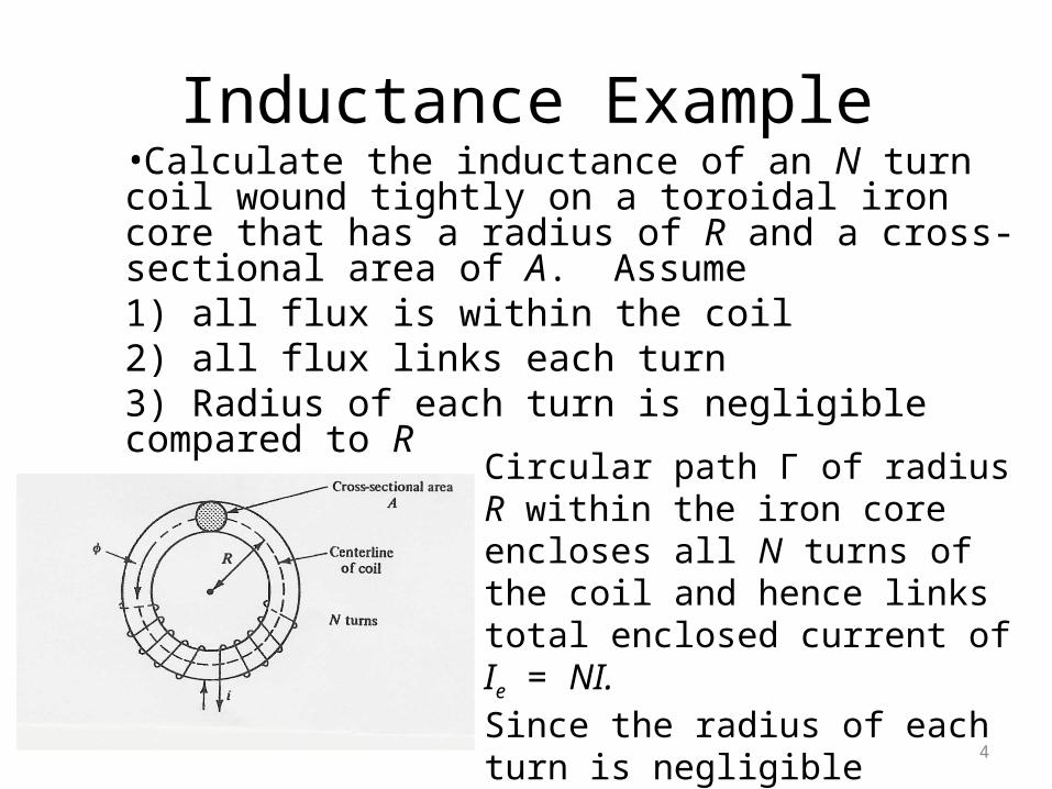
Inductance Example•Calculate the inductance of an N turn coil wound tightly on a toroidal iron core that has a radius of R and a cross-sectional area of A. Assume1) all flux is within the coil 2) all flux links each turn3) Radius of each turn is negligible compared to R
Circular path Γ of radius R within the iron core encloses all N turns of the coil and hence links total enclosed current of Ie = NI.Since the radius of each turn is negligible compared to R, all circular paths within the iron core have radius approximately equal to R. 4

Inductance Example, cont’d
0
2 (path encloses ; path length is 2 ,)
( varies somewhat with , but ignore,) 2
(linear magnetic material,)
(assuming and therefore constant,)
(eac
e
e
r
I d
NI H R I NI R
NIH H R
RB H H
AB H B
N
H l
0
20
h of the turns link flux ,)
2
/ H2
r
r
N
NINAB NA
R
N AL I
R
5
Inductance of a Single Wire•To develop models of transmission lines, we first need to determine the inductance of a single, infinitely long wire. To do this we need to determine the wire’s total flux linkage, including:
1. flux linkages outside of the wire2. flux linkages within the wire
•We’ll assume that the current density within the wire is uniform and that the wire is solid with a radius of r.•In fact, current density is non-uniform, and conductor is stranded, so our calculations will be approximate.
6

Flux Linkages outside of the wireWe'll think of the wire as a single loop "closed" by
a return wire that is infinitely far away. Therefore
= since there is = 1 turn. The flux linking
a length of wire outside it to a distance of
N
R
0A
from
the wire center is:
d length 2
R
r
Idxx
B a7

Flux Linkages outside, cont’d
0A
00
d length 2
Since length = we'll deal with per unit length values,
assumed to be per meter.
lnmeter 2 2Note, this quantity still goes to infinity as
R
r
R
r
Idxx
I Rdx Ix r
R
B a
8

Flux linkages inside of wireCurrent inside conductor tends to travel on the outside
of the conductor due to the skin effect. The penetration
of the current into the conductor is approximated using
1the skin depth = where isf
f the frequency in Hz
and is the conductivity in siemens/meter.
0.066 mFor copper skin depth 0.33 inch at 60Hz.
For derivation we'll assume a uniform current density.
f
9
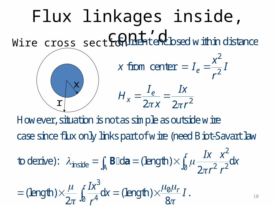
Flux linkages inside, cont’dWire cross section
x
r
2
2
2
Current enclosed within distance
from center
2 2
e
ex
xx I I
rI Ix
Hx r
2
inside 2 2A 0
3
40
However, situation is not as simple as outside wire
case since flux only links part of wire (need Biot-Savart law
to derive): d (length) d2
(length) d (length)2
r
r
Ix xx
r r
Ixx
r
B a
0 .8
r I 10

Line Total Flux & Inductance0 0
0
0
(per meter) ln2 8
(per meter) ln2 4
(per meter) ln2 4
Note, this value still goes to infinity as we let
go to infinity.
Note that inductance depends on
rTotal
rTotal
r
RI I
rR
Ir
RL
r
R
logarithm
of ratio of lengths.
11

Inductance Simplification
0 0 4
0 4
Inductance expression can be simplified using
two exponential identities:
ln( )=ln + ln ln ln ln ln( )
ln ln ln ln2 4 2
ln ln2
r
r
a
r
aab a b a b a e
b
RL R r e
r
L R re
0
4r
ln2 '
Where ' 0.78 for 1r
Rr
r r e r
12

Two Conductor Line Inductance•Key problem with the previous derivation is we assumed no return path for the current. Now consider the case of two wires, each carrying the same current I, but in opposite directions; assume the wires are separated by distance D.
D
Creates counter-clockwise field
Creates aclockwise field
To determine theinductance of eachconductor we integrateas before. Howevernow we get somefield cancellation.
13

Two Conductor Case, cont’d
Key Point: Flux linkage due to currents in each conductor tend to cancel out. Use superposition to get total flux linkage.
For a distance from left conductor that is greater than 2 ,
flux due to the ri
Consider flux linked by l
ght conductor from distan
eft conductor
ce 0 to
can
from distance 0 to
cels the flux due t
e
.
o th
R
R D
D
0 0left
right conductor from to 2 :
Summing the fluxes yields: ln ln2 ' 2
D D
R R DI Ir D
Direction of integration
DD
R
Left Current Right Current14
Two Conductor Inductance
0left
0
0
0
0
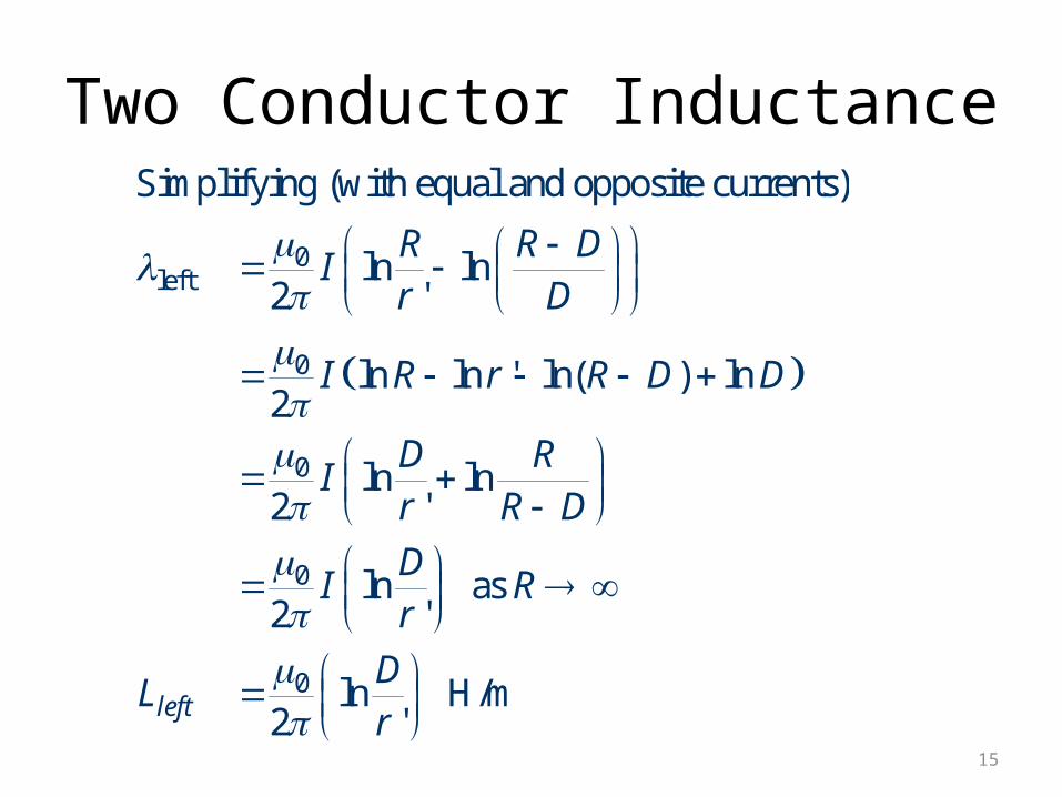
Simplifying (with equal and opposite currents)
ln ln2 '
ln ln ' ln( ) ln2
ln ln2 '
ln as 2 '
ln H/m 2 'left
R R DI
r D
I R r R D D
D RI
r R D
DI R
r
DL
r
15
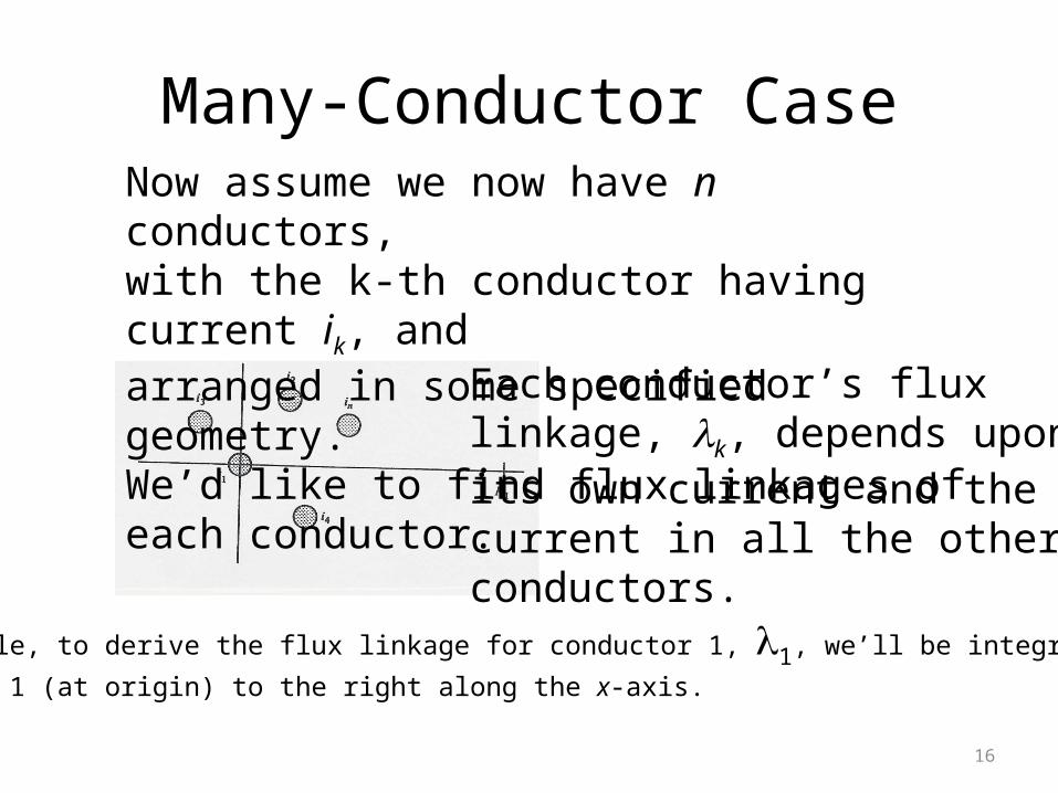
Many-Conductor CaseNow assume we now have n conductors,with the k-th conductor having current ik, andarranged in some specified geometry.We’d like to find flux linkages of each conductor.
Each conductor’s fluxlinkage, k, depends upon its own current and the current in all the other conductors.
For example, to derive the flux linkage for conductor 1, 1, we’ll be integrating from
conductor 1 (at origin) to the right along the x-axis.
16
Many-Conductor Case, cont’d
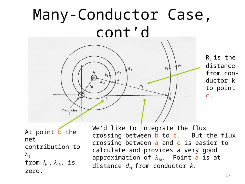
At point b the net contribution to 1
from ik , 1k, is zero.
We’d like to integrate the flux crossing between b to c. But the flux crossing between a and c is easier to calculate and provides a very good approximation of 1k. Point a is at distance d1k from conductor k.
Rk is the distancefrom con-ductor kto pointc.
17
Many-Conductor Case, cont’d
0 1 21 1 2'
12 11
01 2'
12 11
01 1 2 2
1 1 2
0
1
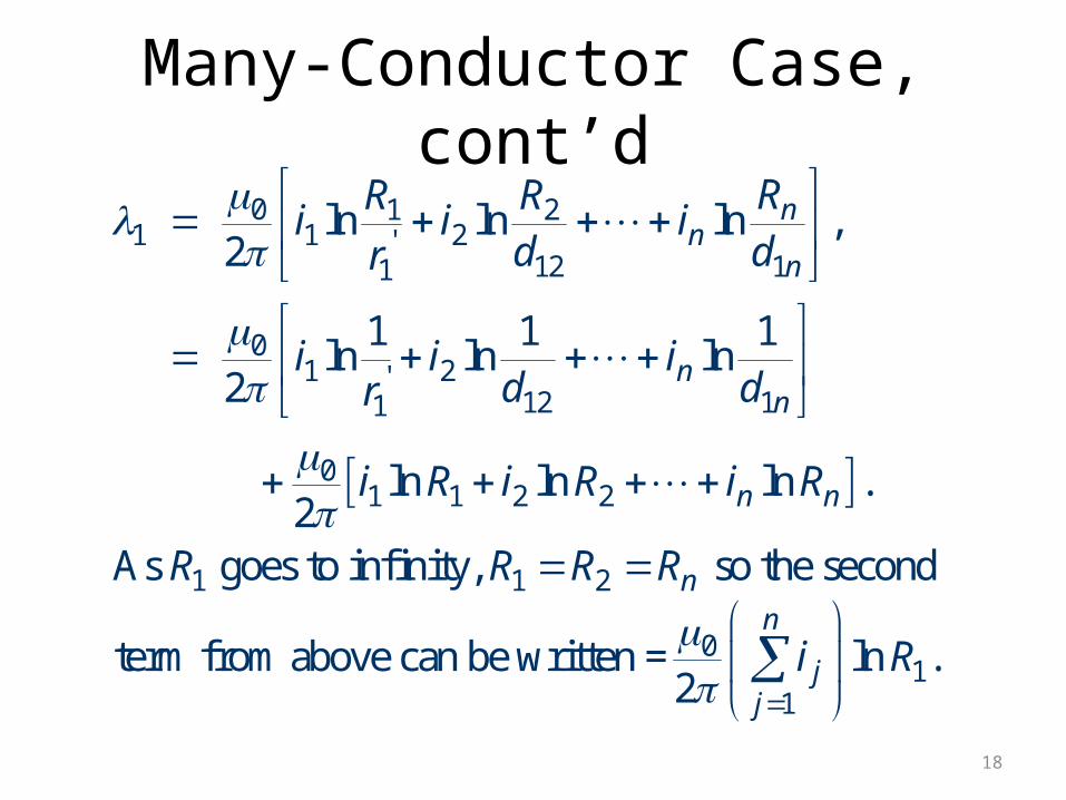
ln ln ln ,2
1 1 1ln ln ln
2
ln ln ln .2
As goes to infinity, so the second
term from above can be written =2
nn
n
nn
n n
n
jj
RR Ri i i
d dr
i i id dr
i R i R i R
R R R R
i
1ln .n
R
18

Many-Conductor Case, cont’d
1
01 1 2'
12 11
11 1 12 2 1
Therefore if 0, which is true in a balanced
three phase system, then the second term is zero and
1 1 1ln ln ln ,
2
System has self and mutual inductan
n
jj
nn
n n
i
i i id dr
L i L i L i
ce.
However, the mutual inductance can be canceled for
balanced 3 systems with symmetry. 19

Symmetric Line Spacing – 69 kV
20

Line Inductance ExampleCalculate the reactance for a balanced 3, 60Hztransmission line with a conductor geometry of anequilateral triangle with D = 5m, r = 1.24cm (Rookconductor) and a length of 5 miles.
0 1 1 1ln( ) ln( ) ln( )
2 'a a b ci i ir D D
Since system is assumed
balanced
a b ci i i
21

Line Inductance Example, cont’d
0
0
70
3
6
Substituting , obtain:
1 1ln ln
2 '
ln .2 '
4 10 5ln ln
2 ' 2 9.67 10
1.25 10 H/m.
Again note logarithm of ratio of distance between
p
a b c
a a a
a
a
i i i
i ir D
Di
r
DL
r
hases to the size of the conductor.22

Line Inductance Example, cont’d6
6
4
Total for 5 mile line
1.25 10 H/m
Converting to reactance
2 60 1.25 10
4.71 10 /m
0.768 /mile
3.79
(this is the total per phase)
The reason we did NOT have mutual inductance
was because
a
a
L
X
X
of the symmetric conductor spacing23

Conductor BundlingTo increase the capacity of high voltage transmissionlines it is very common to use a number of conductors per phase. This is known as conductorbundling. Typical values are two conductors for 345 kV lines, three for 500 kV and four for 765 kV.
24
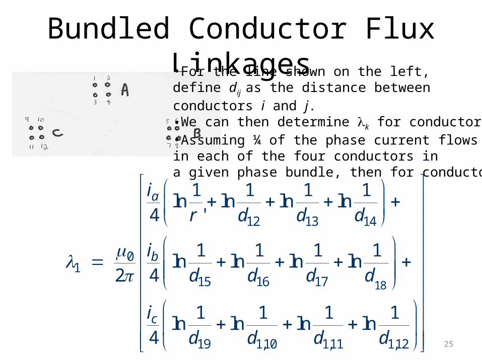
Bundled Conductor Flux Linkages•For the line shown on the left,define dij as the distance between conductors i and j. •We can then determine k for conductor k.•Assuming ¼ of the phase current flowsin each of the four conductors ina given phase bundle, then for conductor 1:
18
12 13 14
01
15 16 17
19 1,10 1,11 1,12
1 1 1 1ln ln ln ln
4 '
1 1 1 1ln ln ln ln
2 4
1 1 1 1ln ln ln ln
4
a
b
c
ir d d d
id d d d
id d d d
25

Bundled Conductors, cont’d
14
12 13 14
01 1
415 16 17 18
14
19 1,10 1,11 1,12
Simplifying
1ln
( ' )
1ln
2 ( )
1ln
( )
a
b
c
ir d d d
id d d d
id d d d
26

Bundled Conductors, cont’d
14
12 13 14
1
12 1
1
14
15 16 17 18 2 3 4
1 19 1
geometric mean radius (GMR) of bundle
( ' ) for our example
( ' ) in general
geometric mean distance (GMD) of
conductor 1 to phase b.
( )
(
b
bb
b
b b b ab
c
R
r d d d
r d d
D
d d d d D D D D
D d d
14
,10 1,11 1,12 2 3 4) c c c acd d D D D D
27

Inductance of Bundle
01
0 01
01
If and
Then
1 1ln ln
2
ln 4 ln2 2
4 ln , which is the 2
self-inductance of wire 1.
ab ac bc a b c
a ab
ab b
b
D D D D i i i
i iR D
D DI I
R R
DL
R
28
Inductance of Bundle, cont’d
01
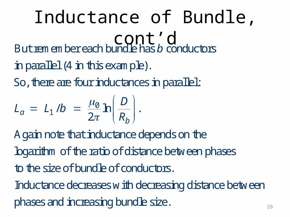
But remember each bundle has conductors
in parallel (4 in this example).
So, there are four inductances in parallel:
/ ln .2
Again note that inductance depends on the
logarithm of t
ab
b
DL L b
R
he ratio of distance between phases
to the size of bundle of conductors.
Inductance decreases with decreasing distance between
phases and increasing bundle size.29

Bundle Inductance Example
0.25 M0.25 M
0.25 M
Consider the previous example of the three phasessymmetrically spaced 5 meters apart using wire with a radius of r = 1.24 cm. Except now assumeeach phase has 4 conductors in a square bundle,spaced 0.25 meters apart. What is the new inductanceper meter?
2 3
13 4
70
1.24 10 m ' 9.67 10 m
9.67 10 0.25 0.25 ( 2 0.25)
0.12 m (ten times bigger than !)
5ln 7.46 10 H/m
2 0.12Bundling reduces inductance.
b
a
r r
R
r
L
30

Transmission Tower Configurations•The problem with the line analysis we’ve done so far is we have assumed a symmetrical tower configuration. •Such a tower configuration is seldom practical.
Typical Transmission Tower Configuration
• Therefore ingeneral Dab Dac Dbc
•Unless something was done this wouldresult in unbalancedPhases.
31

TranspositionTo keep system balanced, over the length of a
transmission line the conductors are “rotated” so each phase occupies each position on tower for an equal distance. This is known as transposition.
Aerial or side view of conductor positions over the lengthof the transmission line. 32

Line Transposition Example
33

Line Transposition Example
34
Transposition Impact on Flux Linkages
0a
12 13
0
13 23
0
23 12
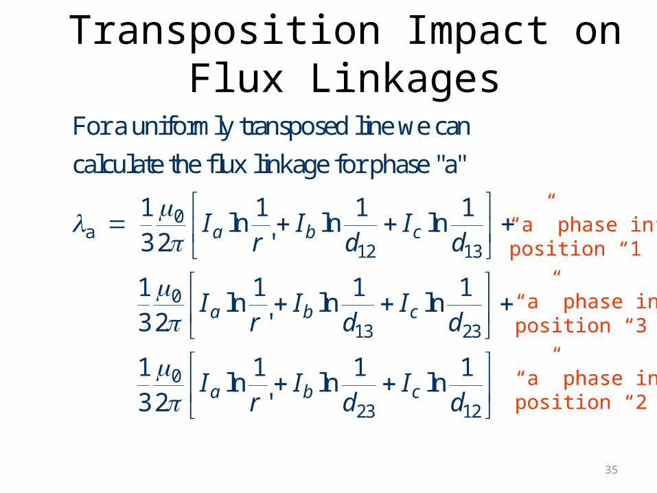
For a uniformly transposed line we can
calculate the flux linkage for phase "a"
1 1 1 1ln ln ln
3 2 '
1 1 1 1ln ln ln
3 2 '
1 1 1 1ln ln ln
3 2 '
a b c
a b c
a b c
I I Ir d d
I I Ir d d
I I Ir d d
“a” phase inposition “1”
“a” phase inposition “3”
“a” phase inposition “2”
35

Transposition Impact, cont’d
13
13
12 13 230
13
12 13 23
Recognizing that
1(ln ln ln ) ln ( )
3
We can simplify so
1 1ln ln
'
21
ln
a b
a
c
a b c abc
I Ir d d d
Id d d
36

Inductance of Transposed Line
1312 13 23
0 0a
70
Define the geometric mean distance (GMD)
Then for a balanced 3 system ( - - )
1 1ln ln ln
2 ' 2 '
Hence
ln 2 10 ln H/m2 ' '
Again, logarithm of ratio
m
a b c
ma a a
m
m ma
D d d d
I I I
DI I I
r D r
D DL
r r
of distance between phases
to conductor size.37

Inductance with Bundling
0
70
If the line is bundled with a geometric mean
radius, , then
ln2
ln 2 10 ln H/m2
b
ma a
b
m ma
b b
R
DI
R
D DL
R R
38

Inductance ExampleCalculate the per phase inductance and
reactance of a balanced 3, 60 Hz, line with:– horizontal phase spacing of 10m – using three conductor bundling with a spacing
between conductors in the bundle of 0.3m. Assume the line is uniformly transposed and
the conductors have a 1cm radius.
39

Inductance Example 13
12 13 23
1/ 3
4
13
bundle bundle bundle
1/ 3
0
,
(10 (2 10) 10) 12.6m,
'= 0.0078m,
( ' ) , where is the
distance between conductors in bundle
( ' 0.3 0.3) 0.0888m,
ln2
9.9 10
r
m
b
ma
b
D d d d
r r e
R r d d d
r
DL
R
7 H/m,
2 (1600m/mile) = 0.6 /mile.a aX fL 40