ee-566 presentation topic: fiber bragg gratings presented by: eric glauber date: 10/29/03
Post on 20-Dec-2015
217 views
TRANSCRIPT

EE-566 Presentation
Topic: Fiber Bragg Gratings
Presented By: Eric Glauber
Date: 10/29/03

Fiber Bragg Grating: Introduction
• The Fiber Bragg Grating (FBG) is a fiber optic passive component exhibiting basic functional attributes of reflection and filtering.
• FBG’s are relatively simple to manufacture, small in dimension, low cost and exhibit good immunity changing ambient conditions and EM radiation.
• FBG’s have replaced bulk optic mirrors & beam splitters in equipment which increases system stability and portability.
Fiber Bragg Grating: Introduction
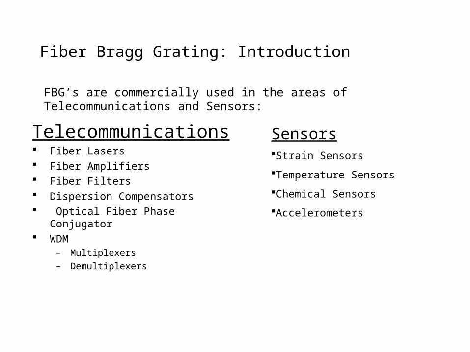
Telecommunications Fiber Lasers Fiber Amplifiers Fiber Filters Dispersion Compensators Optical Fiber Phase Conjugator WDM
– Multiplexers
– Demultiplexers
SensorsStrain Sensors
Temperature Sensors
Chemical Sensors
Accelerometers
FBG’s are commercially used in the areas of Telecommunications and Sensors:

Fiber Bragg Grating: Theory
1978 – Hill et. all
• Phenomenon of photosensitivity in optical fibers
• Exposed Ge-doped core fibers to intense light at 488 or 514 nm
• Induced permanent refractive index changes to the core.

Fiber Bragg Grating: Theory
• FBG is a longitudinal periodic variation of the index of refraction in the core of an optical fiber.
• The spacing of the variation is determined by the wavelength of the light to be reflected.
Bragg
Bragg

Fiber Bragg Grating: Theory
The Bragg Condition is the result of two requirements:1. Energy Conservation: Frequency of incident radiation and reflected radiation is the
same.2. Momentum Conservation: Sum of incident wave vector and grating wave vector
equal the wave vector of the scattered radiation. K + ki = kf
The resulting Bragg Condition is: B = 2neff
• The grating reflects the light at the Bragg wavelength (B) • B is a function of the grating periodicity () and effective index (neff). • Typically; B= 1.5 m, = 0.5m

Fiber Bragg Grating: Theory
• The spectral component reflected (not transmitted) typically has a bandwidth of 0.05 – 0.3 nm.
A general expression for the approximate Full Width Half Maximum bandwidth of a standard grating is given by (S = grating parameter (.5 to 1), N = numbers of grating pains):
Δλ =λ B S( (Δn/2n0)2 + (1/N)2 )1/2
1570 1572 1574 1576 1578
-40
-30
-20
-10
0
Lo
ss in
dB
Wavelength in nm
Reflection Transmission
Fiber Bragg Grating: Theory
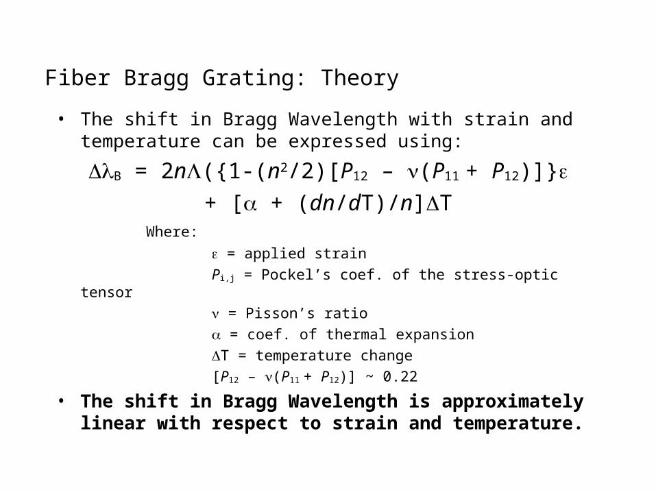
• The shift in Bragg Wavelength with strain and temperature can be expressed using:
B = 2n({1-(n2/2)[P12 – (P11 + P12)]}+ [ + (dn/dT)/n]T
Where:
= applied strain
Pi,j = Pockel’s coef. of the stress-optic tensor
= Pisson’s ratio
= coef. of thermal expansion
T = temperature change
[P12 – (P11 + P12)] ~ 0.22
• The shift in Bragg Wavelength is approximately linear with respect to strain and temperature.

Fiber Bragg Grating: Theory
• The measured strain response at a constant temperature is found to be:
(1/B)B/ = 0.78 x 10⁻⁶-1
• Sensitivity Rule of thumb at B = 1300nm:
0.001nm/

Fiber Bragg Grating: Theory
• The measured temperature response at a constant strain is found to be:
(1/B)B/ T = 6.67 x 10⁻⁶ oC-1
• Sensitivity Rule of thumb at B = 1300nm:
0.009nm/ oC

Fiber Bragg Grating: Theory – Blazed Grating
• Bragg grating planes are tilted at an angle to the fiber axis.
• Light which otherwise would be guided in the fiber core, is coupled into the loosely bound, guided cladding or radiation modes.
• The bandwidth of the trapped out light is dependent on the tilt angle of the grating planes and the strength of the index modulation.
• As shown above, the vector diagram is a result of the conservation of momentum and conservation of energy requirement. The results of applying the law of cosines yealds: Cos(θb) = ׀K 2/׀ v

Fiber Bragg Grating: Theory – Chirped Grating
• Bragg grating has a monotonically varying period as illustrated above.• These gratings can be realized by axially varying either the period of
the grating or the index of refraction of the core or both.• The Bragg Condition becomes: λB = 2neff(z)Λ(z)• The simplest type of chirped grating is one which the grating period
varies linearly with axial length: Λ(z) = Λ0 + Λ(z)

Fiber Bragg Grating: Manufacturing
1989 Meltz et. all.
• Grating written into core by holographic side exposure method
• Exposure with two beam interference pattern of UV light at 244nm
• Focal spot is approx. rectangular, 4mm L X 125 m W.

Fiber Bragg Grating: Manufacturing
Split Beam Interferometer Method

Fiber Bragg Grating: Manufacturing
Interference patternGrating
Coreø 9µm
Claddingø 125µm
LaserBeam
LaserBeam
Fiber

Fiber Bragg Grating: Manufacturing
Novel interferometer technique using a right angled prism.
Inherently more stable -because beams are perturbed similarly by any prism vibration.

Fiber Bragg Grating: Manufacturing
Phase Mask Technique.
• UV is diffracted into –1,0,1 orders by relief grating.
• Input mask is wavelength specific.
• Different B require different phase masks.

Fiber Bragg Grating: Manufacturers
Manufacturers:• Advanced Optics Solutions GMBH• Blue Road Research• 3M Optical OEM Systems• Alcatel Optronics• Boeing• Gould Fiber Optic• MPB Communications• OZ Optics Limited• TeraXion Inc.• Oxford Lasers Inc.• Thorlabs Inc.

Fiber Bragg Grating: Manufacturers
FBG custom design software:

Fiber Bragg Grating: Manufacturers
FBG order form:

Fiber Bragg Grating: Manufacturers
Fiber Bragg Gratings - Application
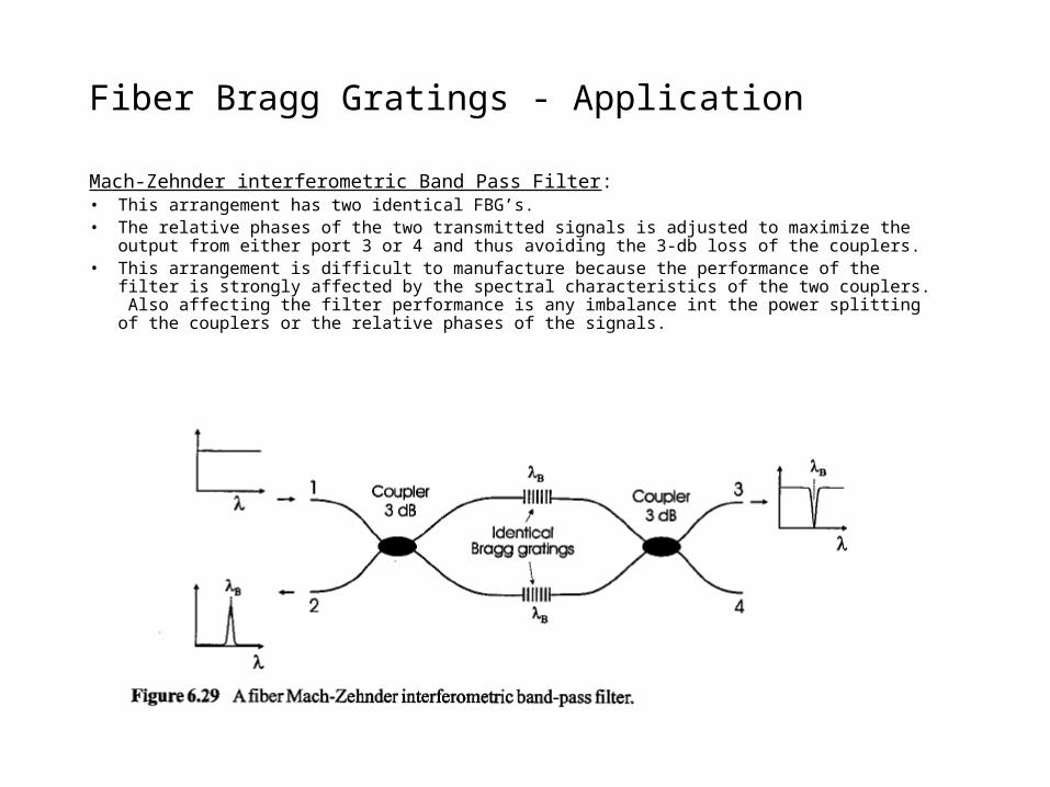
Mach-Zehnder interferometric Band Pass Filter:• This arrangement has two identical FBG’s.• The relative phases of the two transmitted signals is adjusted to maximize the output from either
port 3 or 4 and thus avoiding the 3-db loss of the couplers.• This arrangement is difficult to manufacture because the performance of the filter is strongly
affected by the spectral characteristics of the two couplers. Also affecting the filter performance is any imbalance int the power splitting of the couplers or the relative phases of the signals.
Fiber Bragg Gratings - Application
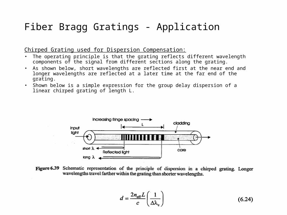
Chirped Grating used for Dispersion Compensation:• The operating principle is that the grating reflects different wavelength components of the
signal from different sections along the grating.• As shown below, short wavelengths are reflected first at the near end and longer wavelengths
are reflected at a later time at the far end of the grating. • Shown below is a simple expression for the group delay dispersion of a linear chirped grating
of length L.
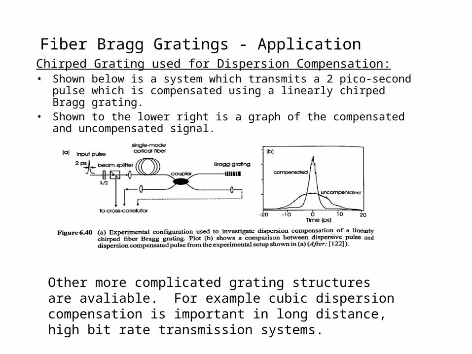
Fiber Bragg Gratings - ApplicationChirped Grating used for Dispersion Compensation:• Shown below is a system which transmits a 2 pico-second pulse which is
compensated using a linearly chirped Bragg grating.• Shown to the lower right is a graph of the compensated and uncompensated
signal.
Other more complicated grating structures are avaliable. For example cubic dispersion compensation is important in long distance, high bit rate transmission systems.

Fiber Bragg Gratings - Application
Mach-Zehnder DWM – Multiplexer / Demultiplexer:• This is the Mach-Zehnder arrangement for a WDM application.
Extraction of channel λk Insertion of channel λk

Fiber Bragg Gratings - Application
Frustrated Coupler Drop Add Multiplexer:• This is composed of a mismatched coupler with a Bragg Grating written into one of
the cores.• Power would not normally be transferred due to the mismatch of the core. With the
Bragg grating, power transfer of the guided mode from port 1 to port 4 can happen if the sum of the propagation constants of the LP01 modes of each core satisfies the Bragg condition: (β01(λ12,1) +β01(λ12,2)) = 2Π/Λ
• This cross coupling transfers the guided optical power at λ12 in core 1 into back propagating optical power in core 2.

Fiber Bragg Gratings - Application
Chemical Sensor:• FBG is blazed into the core at a tilt angle • The FBG Tap radiates a beam out of the core and cladding at an
angle B.

Fiber Bragg Gratings - Application
Chemical Sensor (Continued):• FBG Tap excites fluorescent layer which in turn emits light which
is in turn collected by the core (f1).
Fiber Bragg Gratings – Application, WDM
• In WDM, each FBG sensor is assigned a portion of the source spectrum.
• Enables quasi-distributed sensing of strain, temperature, chemical, etc….
• No. of FBG is a function of:– Source profile width – Grating operational bandwidth

Fiber Bragg Gratings – Application, WDM
• Approx 20 strain sensors can be multiplexed along a single fiber (peak strains of +1000)

Fiber Bragg Gratings – Application, WDM
Time & Wavelength Division Multiplexing:

Fiber Bragg Gratings – ReferencesOthonos, Andreas and Kalli, Kyriacos, “Fiber Bragg Gratings – Fundamentals and Applications in Telecommunications and
Sensing”, Artech House, Inc, 1999.
Hill, K.O., et al., “Photosensitivity in Optical Fiber Waveguides: Application to Reflection Filter Fabrication,” Appl. Phys. Letter, Vol.32 (647-651) 1978.
Kersey, Alan D., et al., “Fiber Grating Sensors,” Journal of Lightwave Technology, Vol. 15, No. 8, August 1997.
Maher, M.H. and E.G. Nawy, “Evaluation of Fiber Optic Bragg Grating Strain Sensor in High Strength Concrete Beams,” Fiber Optic Sensors for Construction Materials and Bridges, pp. 120-133, Farhad Ansari, editor, Technical Publishing Company, Inc., 1998.
Pallas-Areny, R. and J.G. Webster, Sensors and Signal Conditioning, second Ed., John Wiley & Sons, Inc., 2001.
Meltz, G., W.W. Morey and W.H. Glenn, “Formation of Bragg Gratings in Optical Fibers by a Transverse Holographic Method,” Opt. Lett, 14, (823-825) 1989.
Webster, J.G., The Measurement Instrumentation and Sensors Handbook, RC Press, 1999.
http://www.photonics.com/directory/bg/xq/asp/url.viewcat/bgpsa.30125/qx/categories.html
http://www.aos-fiber.com/