eet 110 – survey of electronics chapter 3. figure 3-17 parallel electrical circuit. dale r....
Post on 21-Dec-2015
217 views
TRANSCRIPT

EET 110 – Survey of EET 110 – Survey of ElectronicsElectronics
Chapter 3Chapter 3

FIGURE 3-17FIGURE 3-17 Parallel electrical circuit. Parallel electrical circuit.
Dale R. PatrickDale R. PatrickElectricity and Electronics: A Survey, Electricity and Electronics: A Survey, 5e5e
Copyright ©2002 by Pearson Education, Inc.Copyright ©2002 by Pearson Education, Inc.Upper Saddle River, New Jersey 07458Upper Saddle River, New Jersey 07458
All rights reserved.All rights reserved.

FIGURE 3-18FIGURE 3-18 Current flow in a parallel circuit. Current flow in a parallel circuit.
Dale R. PatrickDale R. PatrickElectricity and Electronics: A Survey, Electricity and Electronics: A Survey, 5e5e
Copyright ©2002 by Pearson Education, Inc.Copyright ©2002 by Pearson Education, Inc.Upper Saddle River, New Jersey 07458Upper Saddle River, New Jersey 07458
All rights reserved.All rights reserved.

FIGURE 3-19FIGURE 3-19 Finding total resistance of a parallel circuit. Finding total resistance of a parallel circuit.
Dale R. PatrickDale R. PatrickElectricity and Electronics: A Survey, Electricity and Electronics: A Survey, 5e5e
Copyright ©2002 by Pearson Education, Inc.Copyright ©2002 by Pearson Education, Inc.Upper Saddle River, New Jersey 07458Upper Saddle River, New Jersey 07458
All rights reserved.All rights reserved.

FIGURE 3-20FIGURE 3-20 Finding total resistance when all resistances are the same. Finding total resistance when all resistances are the same.
Dale R. PatrickDale R. PatrickElectricity and Electronics: A Survey, Electricity and Electronics: A Survey, 5e5e
Copyright ©2002 by Pearson Education, Inc.Copyright ©2002 by Pearson Education, Inc.Upper Saddle River, New Jersey 07458Upper Saddle River, New Jersey 07458
All rights reserved.All rights reserved.

FIGURE 3-21FIGURE 3-21 Three lamps connected in parallel. Three lamps connected in parallel.
Dale R. PatrickDale R. PatrickElectricity and Electronics: A Survey, Electricity and Electronics: A Survey, 5e5e
Copyright ©2002 by Pearson Education, Inc.Copyright ©2002 by Pearson Education, Inc.Upper Saddle River, New Jersey 07458Upper Saddle River, New Jersey 07458
All rights reserved.All rights reserved.

FIGURE 3-22FIGURE 3-22 Sample parallel circuit problem. Sample parallel circuit problem.
Dale R. PatrickDale R. PatrickElectricity and Electronics: A Survey, Electricity and Electronics: A Survey, 5e5e
Copyright ©2002 by Pearson Education, Inc.Copyright ©2002 by Pearson Education, Inc.Upper Saddle River, New Jersey 07458Upper Saddle River, New Jersey 07458
All rights reserved.All rights reserved.

FIGURE 3-23FIGURE 3-23 Making measurements in a parallel circuit: (a) original Making measurements in a parallel circuit: (a) original circuit; (b) circuit set up to measure current through path 1.circuit; (b) circuit set up to measure current through path 1.
Dale R. PatrickDale R. PatrickElectricity and Electronics: A Survey, Electricity and Electronics: A Survey, 5e5e
Copyright ©2002 by Pearson Education, Inc.Copyright ©2002 by Pearson Education, Inc.Upper Saddle River, New Jersey 07458Upper Saddle River, New Jersey 07458
All rights reserved.All rights reserved.
(a)

FIGURE 3-23FIGURE 3-23 continued continued Making measurements in a parallel circuit: (a) Making measurements in a parallel circuit: (a) original circuit; (b) circuit set up to measure current through path 1.original circuit; (b) circuit set up to measure current through path 1.
Dale R. PatrickDale R. PatrickElectricity and Electronics: A Survey, Electricity and Electronics: A Survey, 5e5e
Copyright ©2002 by Pearson Education, Inc.Copyright ©2002 by Pearson Education, Inc.Upper Saddle River, New Jersey 07458Upper Saddle River, New Jersey 07458
All rights reserved.All rights reserved.
(b)

FIGURE 3-24FIGURE 3-24 Simple combination circuit. Simple combination circuit.
Dale R. PatrickDale R. PatrickElectricity and Electronics: A Survey, Electricity and Electronics: A Survey, 5e5e
Copyright ©2002 by Pearson Education, Inc.Copyright ©2002 by Pearson Education, Inc.Upper Saddle River, New Jersey 07458Upper Saddle River, New Jersey 07458
All rights reserved.All rights reserved.

FIGURE 3-25FIGURE 3-25 Combination circuit. Combination circuit.
Dale R. PatrickDale R. PatrickElectricity and Electronics: A Survey, Electricity and Electronics: A Survey, 5e5e
Copyright ©2002 by Pearson Education, Inc.Copyright ©2002 by Pearson Education, Inc.Upper Saddle River, New Jersey 07458Upper Saddle River, New Jersey 07458
All rights reserved.All rights reserved.
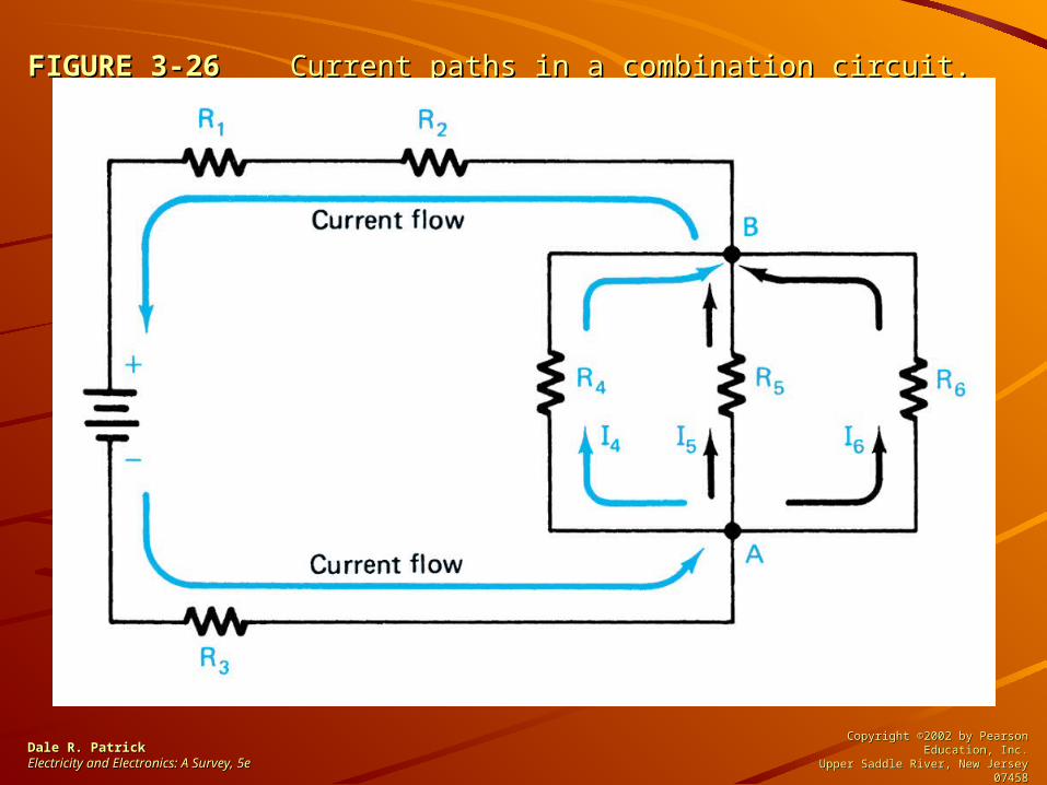
FIGURE 3-26FIGURE 3-26 Current paths in a combination circuit. Current paths in a combination circuit.
Dale R. PatrickDale R. PatrickElectricity and Electronics: A Survey, Electricity and Electronics: A Survey, 5e5e
Copyright ©2002 by Pearson Education, Inc.Copyright ©2002 by Pearson Education, Inc.Upper Saddle River, New Jersey 07458Upper Saddle River, New Jersey 07458
All rights reserved.All rights reserved.

FIGURE 3-27FIGURE 3-27 Combination-circuit example. Combination-circuit example.
Dale R. PatrickDale R. PatrickElectricity and Electronics: A Survey, Electricity and Electronics: A Survey, 5e5e
Copyright ©2002 by Pearson Education, Inc.Copyright ©2002 by Pearson Education, Inc.Upper Saddle River, New Jersey 07458Upper Saddle River, New Jersey 07458
All rights reserved.All rights reserved.

FIGURE 3-28FIGURE 3-28 Kirchhoff’s laws: (a) voltage law example; (b) current law Kirchhoff’s laws: (a) voltage law example; (b) current law examples.examples.
Dale R. PatrickDale R. PatrickElectricity and Electronics: A Survey, Electricity and Electronics: A Survey, 5e5e
Copyright ©2002 by Pearson Education, Inc.Copyright ©2002 by Pearson Education, Inc.Upper Saddle River, New Jersey 07458Upper Saddle River, New Jersey 07458
All rights reserved.All rights reserved.

FIGURE 3-28FIGURE 3-28 continued continued Kirchhoff’s laws: (a) voltage law example; (b) Kirchhoff’s laws: (a) voltage law example; (b) current law examples.current law examples.
Dale R. PatrickDale R. PatrickElectricity and Electronics: A Survey, Electricity and Electronics: A Survey, 5e5e
Copyright ©2002 by Pearson Education, Inc.Copyright ©2002 by Pearson Education, Inc.Upper Saddle River, New Jersey 07458Upper Saddle River, New Jersey 07458
All rights reserved.All rights reserved.
(b)
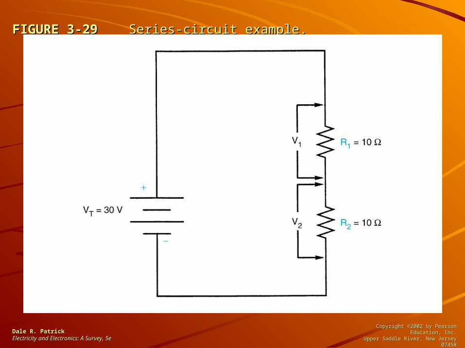
FIGURE 3-29FIGURE 3-29 Series-circuit example. Series-circuit example.
Dale R. PatrickDale R. PatrickElectricity and Electronics: A Survey, Electricity and Electronics: A Survey, 5e5e
Copyright ©2002 by Pearson Education, Inc.Copyright ©2002 by Pearson Education, Inc.Upper Saddle River, New Jersey 07458Upper Saddle River, New Jersey 07458
All rights reserved.All rights reserved.

FIGURE 3-30FIGURE 3-30 Series-circuit example. Series-circuit example.
Dale R. PatrickDale R. PatrickElectricity and Electronics: A Survey, Electricity and Electronics: A Survey, 5e5e
Copyright ©2002 by Pearson Education, Inc.Copyright ©2002 by Pearson Education, Inc.Upper Saddle River, New Jersey 07458Upper Saddle River, New Jersey 07458
All rights reserved.All rights reserved.

FIGURE 3-31FIGURE 3-31 Parallel-circuit example. Parallel-circuit example.
Dale R. PatrickDale R. PatrickElectricity and Electronics: A Survey, Electricity and Electronics: A Survey, 5e5e
Copyright ©2002 by Pearson Education, Inc.Copyright ©2002 by Pearson Education, Inc.Upper Saddle River, New Jersey 07458Upper Saddle River, New Jersey 07458
All rights reserved.All rights reserved.
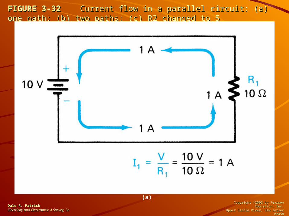
FIGURE 3-32FIGURE 3-32 Current flow in a parallel circuit: (a) one path; (b) two paths; Current flow in a parallel circuit: (a) one path; (b) two paths; (c) R2 changed to 5 (c) R2 changed to 5
Dale R. PatrickDale R. PatrickElectricity and Electronics: A Survey, Electricity and Electronics: A Survey, 5e5e
Copyright ©2002 by Pearson Education, Inc.Copyright ©2002 by Pearson Education, Inc.Upper Saddle River, New Jersey 07458Upper Saddle River, New Jersey 07458
All rights reserved.All rights reserved.
(a)

FIGURE 3-32FIGURE 3-32 continued continued Current flow in a parallel circuit: (a) one path; (b) Current flow in a parallel circuit: (a) one path; (b) two paths; (c) R2 changed to 5 two paths; (c) R2 changed to 5
Dale R. PatrickDale R. PatrickElectricity and Electronics: A Survey, Electricity and Electronics: A Survey, 5e5e
Copyright ©2002 by Pearson Education, Inc.Copyright ©2002 by Pearson Education, Inc.Upper Saddle River, New Jersey 07458Upper Saddle River, New Jersey 07458
All rights reserved.All rights reserved.
(b)

FIGURE 3-32FIGURE 3-32 continued continued Current flow in a parallel circuit: (a) one path; (b) Current flow in a parallel circuit: (a) one path; (b) two paths; (c) R2 changed to 5 two paths; (c) R2 changed to 5
Dale R. PatrickDale R. PatrickElectricity and Electronics: A Survey, Electricity and Electronics: A Survey, 5e5e
Copyright ©2002 by Pearson Education, Inc.Copyright ©2002 by Pearson Education, Inc.Upper Saddle River, New Jersey 07458Upper Saddle River, New Jersey 07458
All rights reserved.All rights reserved.
(c)

FIGURE 3-33FIGURE 3-33 Combination-circuit example. Combination-circuit example.
Dale R. PatrickDale R. PatrickElectricity and Electronics: A Survey, Electricity and Electronics: A Survey, 5e5e
Copyright ©2002 by Pearson Education, Inc.Copyright ©2002 by Pearson Education, Inc.Upper Saddle River, New Jersey 07458Upper Saddle River, New Jersey 07458
All rights reserved.All rights reserved.

FIGURE 3-34FIGURE 3-34 Combination-circuit example. Combination-circuit example.
Dale R. PatrickDale R. PatrickElectricity and Electronics: A Survey, Electricity and Electronics: A Survey, 5e5e
Copyright ©2002 by Pearson Education, Inc.Copyright ©2002 by Pearson Education, Inc.Upper Saddle River, New Jersey 07458Upper Saddle River, New Jersey 07458
All rights reserved.All rights reserved.

FIGURE 3-35FIGURE 3-35 Formulas for finding voltage, current, resistance, or power. Formulas for finding voltage, current, resistance, or power.
Dale R. PatrickDale R. PatrickElectricity and Electronics: A Survey, Electricity and Electronics: A Survey, 5e5e
Copyright ©2002 by Pearson Education, Inc.Copyright ©2002 by Pearson Education, Inc.Upper Saddle River, New Jersey 07458Upper Saddle River, New Jersey 07458
All rights reserved.All rights reserved.

FIGURE 3-36FIGURE 3-36 Finding power in a series circuit. Finding power in a series circuit.
Dale R. PatrickDale R. PatrickElectricity and Electronics: A Survey, Electricity and Electronics: A Survey, 5e5e
Copyright ©2002 by Pearson Education, Inc.Copyright ©2002 by Pearson Education, Inc.Upper Saddle River, New Jersey 07458Upper Saddle River, New Jersey 07458
All rights reserved.All rights reserved.

FIGURE 3-37FIGURE 3-37 Finding power values in a parallel circuit. Finding power values in a parallel circuit.
Dale R. PatrickDale R. PatrickElectricity and Electronics: A Survey, Electricity and Electronics: A Survey, 5e5e
Copyright ©2002 by Pearson Education, Inc.Copyright ©2002 by Pearson Education, Inc.Upper Saddle River, New Jersey 07458Upper Saddle River, New Jersey 07458
All rights reserved.All rights reserved.

FIGURE 3-38FIGURE 3-38 Problem that shows maximum power transfer. Problem that shows maximum power transfer.
Dale R. PatrickDale R. PatrickElectricity and Electronics: A Survey, Electricity and Electronics: A Survey, 5e5e
Copyright ©2002 by Pearson Education, Inc.Copyright ©2002 by Pearson Education, Inc.Upper Saddle River, New Jersey 07458Upper Saddle River, New Jersey 07458
All rights reserved.All rights reserved.
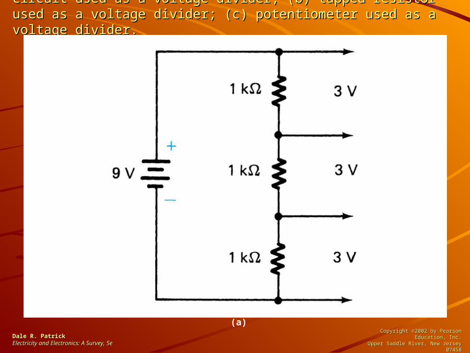
FIGURE 3-39FIGURE 3-39 Voltage-divider circuits: (a) series dc circuit used as a Voltage-divider circuits: (a) series dc circuit used as a voltage divider; (b) tapped resistor used as a voltage divider; (c) voltage divider; (b) tapped resistor used as a voltage divider; (c) potentiometer used as a voltage divider.potentiometer used as a voltage divider.
Dale R. PatrickDale R. PatrickElectricity and Electronics: A Survey, Electricity and Electronics: A Survey, 5e5e
Copyright ©2002 by Pearson Education, Inc.Copyright ©2002 by Pearson Education, Inc.Upper Saddle River, New Jersey 07458Upper Saddle River, New Jersey 07458
All rights reserved.All rights reserved.
(a)

FIGURE 3-39FIGURE 3-39 continued continued Voltage-divider circuits: (a) series dc circuit used Voltage-divider circuits: (a) series dc circuit used as a voltage divider; (b) tapped resistor used as a voltage divider; (c) as a voltage divider; (b) tapped resistor used as a voltage divider; (c) potentiometer used as a voltage divider.potentiometer used as a voltage divider.
Dale R. PatrickDale R. PatrickElectricity and Electronics: A Survey, Electricity and Electronics: A Survey, 5e5e
Copyright ©2002 by Pearson Education, Inc.Copyright ©2002 by Pearson Education, Inc.Upper Saddle River, New Jersey 07458Upper Saddle River, New Jersey 07458
All rights reserved.All rights reserved.
(b)

FIGURE 3-39FIGURE 3-39 continued continued Voltage-divider circuits: (a) series dc circuit used Voltage-divider circuits: (a) series dc circuit used as a voltage divider; (b) tapped resistor used as a voltage divider; (c) as a voltage divider; (b) tapped resistor used as a voltage divider; (c) potentiometer used as a voltage divider.potentiometer used as a voltage divider.
Dale R. PatrickDale R. PatrickElectricity and Electronics: A Survey, Electricity and Electronics: A Survey, 5e5e
Copyright ©2002 by Pearson Education, Inc.Copyright ©2002 by Pearson Education, Inc.Upper Saddle River, New Jersey 07458Upper Saddle River, New Jersey 07458
All rights reserved.All rights reserved.
(c)

FIGURE 3-40FIGURE 3-40 Voltage-divider design. Voltage-divider design.
Dale R. PatrickDale R. PatrickElectricity and Electronics: A Survey, Electricity and Electronics: A Survey, 5e5e
Copyright ©2002 by Pearson Education, Inc.Copyright ©2002 by Pearson Education, Inc.Upper Saddle River, New Jersey 07458Upper Saddle River, New Jersey 07458
All rights reserved.All rights reserved.
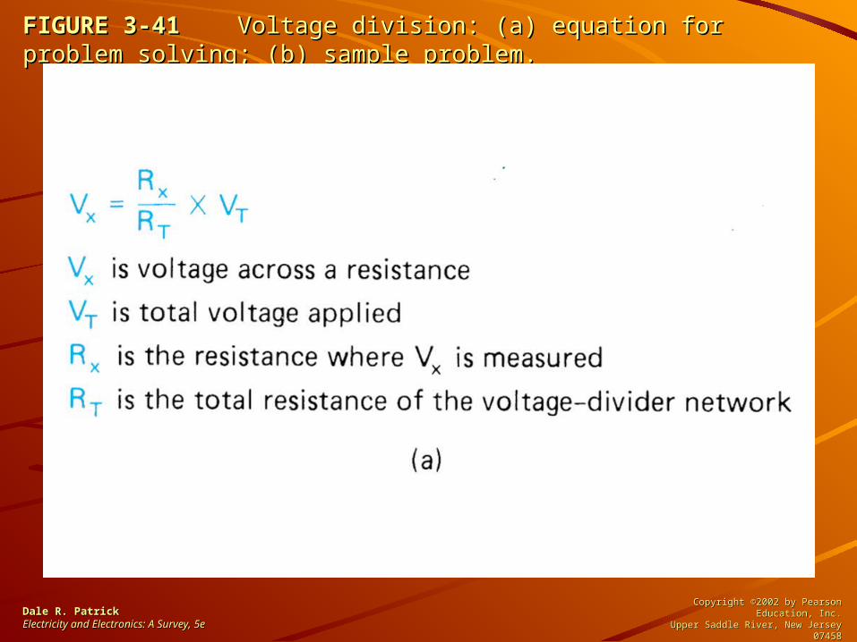
FIGURE 3-41FIGURE 3-41 Voltage division: (a) equation for problem solving; (b) Voltage division: (a) equation for problem solving; (b) sample problem.sample problem.
Dale R. PatrickDale R. PatrickElectricity and Electronics: A Survey, Electricity and Electronics: A Survey, 5e5e
Copyright ©2002 by Pearson Education, Inc.Copyright ©2002 by Pearson Education, Inc.Upper Saddle River, New Jersey 07458Upper Saddle River, New Jersey 07458
All rights reserved.All rights reserved.
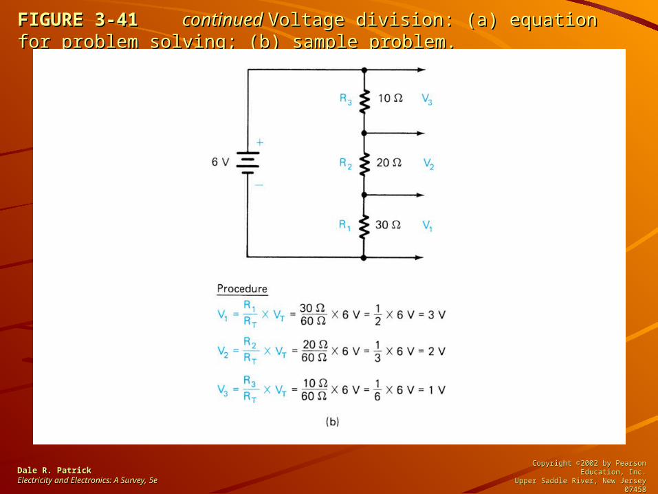
FIGURE 3-41FIGURE 3-41 continued continued Voltage division: (a) equation for problem solving; Voltage division: (a) equation for problem solving; (b) sample problem.(b) sample problem.
Dale R. PatrickDale R. PatrickElectricity and Electronics: A Survey, Electricity and Electronics: A Survey, 5e5e
Copyright ©2002 by Pearson Education, Inc.Copyright ©2002 by Pearson Education, Inc.Upper Saddle River, New Jersey 07458Upper Saddle River, New Jersey 07458
All rights reserved.All rights reserved.

FIGURE 3-42FIGURE 3-42 Negative voltage derived from a voltage divider. Negative voltage derived from a voltage divider.
Dale R. PatrickDale R. PatrickElectricity and Electronics: A Survey, Electricity and Electronics: A Survey, 5e5e
Copyright ©2002 by Pearson Education, Inc.Copyright ©2002 by Pearson Education, Inc.Upper Saddle River, New Jersey 07458Upper Saddle River, New Jersey 07458
All rights reserved.All rights reserved.

FIGURE 3-43FIGURE 3-43 Voltage-divider design problem: (a) circuit; (b) voltage Voltage-divider design problem: (a) circuit; (b) voltage values.values.
Dale R. PatrickDale R. PatrickElectricity and Electronics: A Survey, Electricity and Electronics: A Survey, 5e5e
Copyright ©2002 by Pearson Education, Inc.Copyright ©2002 by Pearson Education, Inc.Upper Saddle River, New Jersey 07458Upper Saddle River, New Jersey 07458
All rights reserved.All rights reserved.
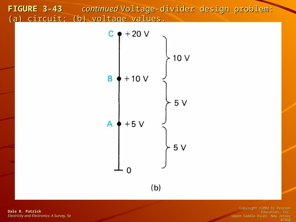
FIGURE 3-43FIGURE 3-43 continued continued Voltage-divider design problem: (a) circuit; (b) Voltage-divider design problem: (a) circuit; (b) voltage values.voltage values.
Dale R. PatrickDale R. PatrickElectricity and Electronics: A Survey, Electricity and Electronics: A Survey, 5e5e
Copyright ©2002 by Pearson Education, Inc.Copyright ©2002 by Pearson Education, Inc.Upper Saddle River, New Jersey 07458Upper Saddle River, New Jersey 07458
All rights reserved.All rights reserved.

FIGURE 3-44FIGURE 3-44 Kirchhoff’s voltage law: (a) voltage drop procedure; (b) Kirchhoff’s voltage law: (a) voltage drop procedure; (b) algebraic procedure.algebraic procedure.
Dale R. PatrickDale R. PatrickElectricity and Electronics: A Survey, Electricity and Electronics: A Survey, 5e5e
Copyright ©2002 by Pearson Education, Inc.Copyright ©2002 by Pearson Education, Inc.Upper Saddle River, New Jersey 07458Upper Saddle River, New Jersey 07458
All rights reserved.All rights reserved.

FIGURE 3-45FIGURE 3-45 Voltage law example. Voltage law example.
Dale R. PatrickDale R. PatrickElectricity and Electronics: A Survey, Electricity and Electronics: A Survey, 5e5e
Copyright ©2002 by Pearson Education, Inc.Copyright ©2002 by Pearson Education, Inc.Upper Saddle River, New Jersey 07458Upper Saddle River, New Jersey 07458
All rights reserved.All rights reserved.
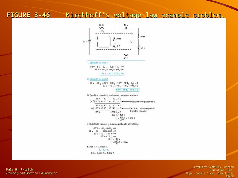
FIGURE 3-46FIGURE 3-46 Kirchhoff’s voltage law example problem. Kirchhoff’s voltage law example problem.
Dale R. PatrickDale R. PatrickElectricity and Electronics: A Survey, Electricity and Electronics: A Survey, 5e5e
Copyright ©2002 by Pearson Education, Inc.Copyright ©2002 by Pearson Education, Inc.Upper Saddle River, New Jersey 07458Upper Saddle River, New Jersey 07458
All rights reserved.All rights reserved.

FIGURE 3-47FIGURE 3-47 The superposition method: (a) original circuit; (b) circuit with The superposition method: (a) original circuit; (b) circuit with 30-V source shorted; © circuit with 10-V source shorted; (d) original circuit 30-V source shorted; © circuit with 10-V source shorted; (d) original circuit with currents recorded.with currents recorded.
Dale R. PatrickDale R. PatrickElectricity and Electronics: A Survey, Electricity and Electronics: A Survey, 5e5e
Copyright ©2002 by Pearson Education, Inc.Copyright ©2002 by Pearson Education, Inc.Upper Saddle River, New Jersey 07458Upper Saddle River, New Jersey 07458
All rights reserved.All rights reserved.

FIGURE 3-48FIGURE 3-48 Thevinin equivalent circuit. Thevinin equivalent circuit.
Dale R. PatrickDale R. PatrickElectricity and Electronics: A Survey, Electricity and Electronics: A Survey, 5e5e
Copyright ©2002 by Pearson Education, Inc.Copyright ©2002 by Pearson Education, Inc.Upper Saddle River, New Jersey 07458Upper Saddle River, New Jersey 07458
All rights reserved.All rights reserved.

FIGURE 3-49FIGURE 3-49 Using the Thevinin method for a one-source circuit: (a) Using the Thevinin method for a one-source circuit: (a) original circuit; (b) problem-solving procedure; (c) Thevinin equivalent original circuit; (b) problem-solving procedure; (c) Thevinin equivalent circuit.circuit.
Dale R. PatrickDale R. PatrickElectricity and Electronics: A Survey, Electricity and Electronics: A Survey, 5e5e
Copyright ©2002 by Pearson Education, Inc.Copyright ©2002 by Pearson Education, Inc.Upper Saddle River, New Jersey 07458Upper Saddle River, New Jersey 07458
All rights reserved.All rights reserved.

FIGURE 3-50FIGURE 3-50 Determining circuit configuration for finding RTH. Determining circuit configuration for finding RTH.
Dale R. PatrickDale R. PatrickElectricity and Electronics: A Survey, Electricity and Electronics: A Survey, 5e5e
Copyright ©2002 by Pearson Education, Inc.Copyright ©2002 by Pearson Education, Inc.Upper Saddle River, New Jersey 07458Upper Saddle River, New Jersey 07458
All rights reserved.All rights reserved.

FIGURE 3-51FIGURE 3-51 Calculating load current and voltage output. Calculating load current and voltage output.
Dale R. PatrickDale R. PatrickElectricity and Electronics: A Survey, Electricity and Electronics: A Survey, 5e5e
Copyright ©2002 by Pearson Education, Inc.Copyright ©2002 by Pearson Education, Inc.Upper Saddle River, New Jersey 07458Upper Saddle River, New Jersey 07458
All rights reserved.All rights reserved.
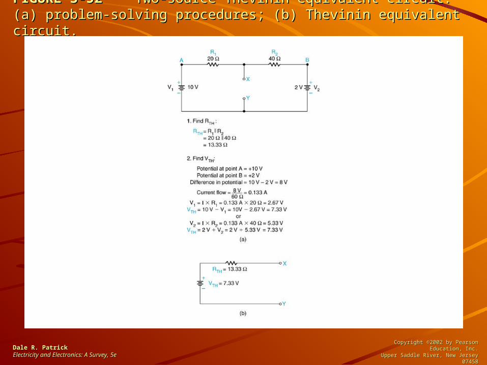
FIGURE 3-52FIGURE 3-52 Two-source Thevinin equivalent circuit: (a) problem-solving Two-source Thevinin equivalent circuit: (a) problem-solving procedures; (b) Thevinin equivalent circuit.procedures; (b) Thevinin equivalent circuit.
Dale R. PatrickDale R. PatrickElectricity and Electronics: A Survey, Electricity and Electronics: A Survey, 5e5e
Copyright ©2002 by Pearson Education, Inc.Copyright ©2002 by Pearson Education, Inc.Upper Saddle River, New Jersey 07458Upper Saddle River, New Jersey 07458
All rights reserved.All rights reserved.

FIGURE 3-53FIGURE 3-53 Norton equivalent circuit. Norton equivalent circuit.
Dale R. PatrickDale R. PatrickElectricity and Electronics: A Survey, Electricity and Electronics: A Survey, 5e5e
Copyright ©2002 by Pearson Education, Inc.Copyright ©2002 by Pearson Education, Inc.Upper Saddle River, New Jersey 07458Upper Saddle River, New Jersey 07458
All rights reserved.All rights reserved.

FIGURE 3-54FIGURE 3-54 Norton equivalent circuit procedure: (a) problem-solving Norton equivalent circuit procedure: (a) problem-solving procedure; (b) Norton equivalent circuit.procedure; (b) Norton equivalent circuit.
Dale R. PatrickDale R. PatrickElectricity and Electronics: A Survey, Electricity and Electronics: A Survey, 5e5e
Copyright ©2002 by Pearson Education, Inc.Copyright ©2002 by Pearson Education, Inc.Upper Saddle River, New Jersey 07458Upper Saddle River, New Jersey 07458
All rights reserved.All rights reserved.

FIGURE 3-55FIGURE 3-55 Bridge circuit. Bridge circuit.
Dale R. PatrickDale R. PatrickElectricity and Electronics: A Survey, Electricity and Electronics: A Survey, 5e5e
Copyright ©2002 by Pearson Education, Inc.Copyright ©2002 by Pearson Education, Inc.Upper Saddle River, New Jersey 07458Upper Saddle River, New Jersey 07458
All rights reserved.All rights reserved.

FIGURE 3-56FIGURE 3-56 Simplification of a bridge circuit. Simplification of a bridge circuit.
Dale R. PatrickDale R. PatrickElectricity and Electronics: A Survey, Electricity and Electronics: A Survey, 5e5e
Copyright ©2002 by Pearson Education, Inc.Copyright ©2002 by Pearson Education, Inc.Upper Saddle River, New Jersey 07458Upper Saddle River, New Jersey 07458
All rights reserved.All rights reserved.

FIGURE 3-57FIGURE 3-57 Calculating load current and voltage output of a bridge Calculating load current and voltage output of a bridge circuit.circuit.
Dale R. PatrickDale R. PatrickElectricity and Electronics: A Survey, Electricity and Electronics: A Survey, 5e5e
Copyright ©2002 by Pearson Education, Inc.Copyright ©2002 by Pearson Education, Inc.Upper Saddle River, New Jersey 07458Upper Saddle River, New Jersey 07458
All rights reserved.All rights reserved.