effect of aluminium powder addition in … i/ijaet vol i issue iii... · effect of aluminium powder...
TRANSCRIPT

International Journal of Advanced Engineering Technology E-ISSN 0976-3945
IJAET/Vol.I/ Issue III/Oct.-Dec.,2010/13-24
Research Article
EFFECT OF ALUMINIUM POWDER ADDITION IN
DIELECTRIC DURING ELECTRIC DISCHARGE MACHINING
OF HASTELLOY ON MACHINING PERFORMANCE USING
REVERSE POLARITY 1Saurabh Sharma, *
2Anil Kumar,
3Naveen Beri
4Dinesh Kumar
Address for Correspondence 1,4 Dept. of Mechanical Engineering, S.S.C.E.T Badhani Pathankot, (Pb.) India.
*2, 3 Dept. of Mechanical Engineering, BCET Gurdaspur, (Pb.) India.
E-mail: [email protected], [email protected],[email protected],
ABSTRACT The addition of powder particles suspended in dielectric fluid of electrical discharge machining (EDM) modifies
some process characteristics and creates the condition to achieve higher machining performance. In this paper
attempt has been made to study the effect of aluminium powder on the machining performance of conventional
EDM with reverse polarity. The machining performance is evaluated in terms of material removal rate, tool
wear rate, percentage wear rate, surface roughness. Concentration and grain size of aluminium powder are taken
as the input powder parameters and its effect are presented on machining performance. It is found
experimentally that powder characteristics significantly affect machining characteristics.
KEYWORDS: Electrical discharge machining, Powder-Mixed dielectric electrical discharge machining,
Aluminium powder, material removal rate, tool wear rate, percentage wear rate, surface roughness and polarity.
1. INTRODUCTION
Since 1940 considerable research efforts have
fostered a deep understanding, prediction and
control of the electric discharge machining
process (EDM). The development of the super
tough electrical conductive material such as
hastelloy, carbides, stainless steel, nitralloy
etc. resulted in development of the non-
traditional machining processes. These
materials are difficult to machine by
conventional machining process, & have wide
range of applications in industry. EDM has
been widely used is a removal process to
manufacture parts, dies & moulds for long
time now. In EDM thermal energy is used to
machine all electrical conductive materials of
any hardness & toughness. Since there is no
direct contact between the tool electrode &
work piece in EDM, machining defects like
mechanical stresses, clattering & vibration do
not create problem during machining. In the
past few years, powder-mixed dielectric
electric discharge machining (PMD-EDM)
emerges as a new technique to enhance the
process capabilities. In PMD-EDM a suitable
metal powder (aluminium, chromium, copper,
silicon carbide etc.) is mixed into the dielectric
used in EDM. When a voltage in the range of
80 to 320 V is applied between the tools and
the work piece placed close to each other an
electric field of the range 105 - 10
7 V/m is
generated. The additive particles suspended in
the dielectric has important influence on the
discharge process; increase both the gap
distance & the discharging rate. The high
electric field energises the conductive powder
particles. These conductive particles form
chains at different places under sparking area,
which bridges the gap between tool electrode
& work piece material. Due to this bridging
effect, the gap voltage & insulting strength of
the dielectric decreases, this causes easy short-
circuiting and hence early explosion in the gap
between the electrode and the work piece. At
the same time the suspended particles in the
dielectric enlarged the plasma channel,
because of which electric density decreases
and hence uniform distribution of the sparking
takes place. Very little literature is available
on PMD-EDM on reverse polarity.

International Journal of Advanced Engineering Technology E-ISSN 0976-3945
IJAET/Vol.I/ Issue III/Oct.-Dec.,2010/13-24
Researchers have done work to improve the
surface finish and machining output
Parameters for various hard and tough
materials by adding different metal powder
during machining. However no work has been
reported on the machining characteristics of
hastelloy using reverse polarity on EDM. The
major applications of the Hastelloy are making
of pressure vessels of nuclear and chemical
industry and aerospace engine parts etc. The
objective of the present research work is to
examine the variation of material removal rate,
tool wear rate and surface roughness with
variation of the two input parameters i.e. grain
size of the aluminium Powder particles and
concentration of the aluminium powder in the
dielectric fluid of EDM using the reverse
polarity.
2. LITERATURE SURVEY
Erden A., et al., [1] Reported during the
machining of mild steel that the machining
rate increases by the addition of powder
particles (aluminium, copper, iron) in the
dielectric fluid of dielectric machining. Here
improvement in the Break Down
characteristics of the dielectric fluid is
observed with the addition of powder particles,
but after a certain critical concentration of
powder short circuiting take place which
causes poor machining. Jeswani M.L., et al.,
[2] 1981 Study the effect of addition of
graphite powder to kerosene used as dielectric
fluid in the EDM. He concluded that addition
of about 4gm/litre of fine powder having
average size of particle as 10µm increases the
MRR (Material Removal Rate) by 60% and
TWR (tool wear rate) by 15% in electrical
discharge machine. Wear ratio is also reduced
by 30%. He concluded that there is 30%
reduction in the breakdown voltage of
kerosene at spark gap of 50µm was observed.
Narumiya H., et al., [3] used silicon,
aluminium and graphite as powder materials.
The concentration range of the powder was
between 2gm/l to 40gm/l. Their conclusion
showed that the gap distance increases with
the powder concentration and is larger for the
aluminium powder but there is no direct
relation between the surface roughness and the
gap distance. The best results concerning the
surface finish were achieved for low powder
concentrations levels and that also for silicon
and graphite powders. Kobayashi K., et al., [4]
have concluded that silicon powder mixed in
the dielectric improves the surface finish of
SKD-61 tool steel. It has also been observed,
however, that at specific machining conditions
in the EDM of steel the aluminium and
graphite powders generate better surface
roughness than silicon powder. Wong Y.S., et
al., [5] Study the powder mixed dielectric
electric discharge machining (PMD-EDM) by
employing a current of 1A and pulse on time
as 0.75µs to produce a near mirror finish on
SKH-54 tool steel. The conclusion was that
the resulting machining surface was composed
of well defined, uniformly sized, smoothly
overlapped and shallow craters. The analysis
was carried out by varying the silicon powder
concentration and the flushing flow rate.
Furutani K., et al., [6] Used titanium powder
in dielectric fluid (Kerosene) and found that
the layer of titanium carbide of hardness
1600HV (Vickers hardness number) on a
carbon steel with negative polarized copper
electrode, peak current 3A and 2 µs pulse
duration. Titanium and titanium Carbide are
found in X-Ray diffraction (XRD) analysis of
machine surface. It was concluded that the
breakdown of dielectric takes place and carbon
came from it. Tzeng Y.F., et al., [7] examines
the effect of powder characteristics on
machining efficiency of electrical discharge
machining. They reach to a conclusion that 70-
International Journal of Advanced Engineering Technology E-ISSN 0976-3945
IJAET/Vol.I/ Issue III/Oct.-Dec.,2010/13-24
80nm powder suspended in dielectric produces
the greatest material removal rate and least
increase in the spark gap. Yan BH., et al., [8]
studied the electric discharge machining with
powder suspended working media and
reported that the gap length become shorter
regardless of a mixed powder with a decrease
of the pulse duration at a duty factor of 0.5.
Kozak J., et al., [9] Reported that the material
removal rate and tool wear rate were decreased
by addition of powder. Consequently the
machined surface becomes smooth. Peças P,
Henriques E., et al., [10] studied the
relationship between the roughness and pulse
energy under a few sets of the conditions in
the removal process. However, the influence
of the energy was not systematically analysed.
Klocke F., et al., [11] Used HSFC high speed
forming camera technique to find out that in
comparison to standard electrode, the
aluminium mixed dielectric forms larger
plasma channel. It was concluded that
discharge energy distribution is on the larger
part on the work piece surface. The type and
concentration of the powder mixed in the
dielectric fluid also found to have direct effect
on the machining performance output. Wu
KL., et al., [12] Study the problem of powder
settling by adding a surfactant with aluminium
powder in dielectric fluid and observed that a
surface roughness (Ra value) of less than
0.2µm. This is because of more apparent
discharge distribution. It was also reported that
negative polarity of the tool resulted in better
hardness of the surface. Kansal H.K., et al.,
[13] reported that the addition of Silicon
powder into the dielectric fluid of EDM and an
enhanced rate of material removal and surface
finish. Yeo S H., et al., [14] The experiments
were conducted using dielectric with and
without additive and at low discharge energies
of 2.5µJ, 5µJ and 25µJ, and was observed that
a considerable difference in crater
morphology is seen between craters in
dielectric with and without the powder at low
discharge energy of 2.5µJ, 5µJ and 25µJ. More
circular shapes with smaller diameters are
produced with powder additive as compared to
without powder additive. Craters with the
additives are smaller and have more consistent
depth than in dielectric without additive. They
reported that dielectric with additive in it
lower the amount of discharge flowing
between the work piece and the tool electrode
and slows down the rate at which these
charges flow. Peças P., et al., [15] Study the
effect of silicon powder particles suspended in
dielectric fluid. The powder concentration and
flushing flow rate are two input parameters.
They reach to a conclusion that even for small
level of powder concentration there is evident
amount of reduction in crater depth, crater
diameter and the white layer thickness. They
reported that for a particular experimental
configuration used, we can find the powder
concentration that generates better surface
morphology. It was observed that there is
dielectric flow rate that minimises the surface
roughness for each electrode area and for
larger flow rates, no positive effect on the
surface morphology. Furutani K., et al., [16]
the conditions for deposition machining by Ti
powder suspended EDM was investigated with
respect to discharge current and pulse duration
in this paper. They concluded that the
discharge energy affected the deposit able
condition range. TiC could be deposited in the
case that both discharge energy and powder
density was small. They reported that the
hardness of the deposition achieved was
2000Hv. The matrix surface was also
hardened. Kumar S., et al., [17] found that
significant amount of material transfer takes
place from the manganese powder suspended
International Journal of Advanced Engineering Technology E-ISSN 0976-3945
IJAET/Vol.I/ Issue III/Oct.-Dec.,2010/13-24
in dielectric fluid to the machined surface
under appropriate machining conditions which
changes the surface composition and its
properties. They reported that percentage of
manganese increased to0.95% from 0.52% and
that of carbon to 1.03% from 0.82% that result
in increase in the micro hardness. For surface
alloying favourable machining conditions
were found to be low peak current (4 A),
shorter pulse on-time (5µs), longer pulse off-
time (85µs), and negative polarity of the tool
electrode.
3. EXPERIMENTAL SETUP
Experiments were conducted on smart ZNC
EDM machine Electronica make. The
dimensions of the working tank of ZNC EDM
are 800mm X 500mm X 350mm. Working
tank contains the dielectric fluid and with
these dimension the tank contains large
amount of dielectric. So it requires large
amount of aluminium powder to get the
desired amount of concentration of powder. To
avoid this problem a new container was
developed with a capacity of 6.5liter for the
EDM oil. The container was filled with EDM
oil and placed in the empty working tank.
Experiments were performed in that container.
Hastelloy Steel was used as a work material
and standard EDM oil was used. To hold the
work piece a special type fixture was made.
Container was filled with EDM oil and the
fixture was placed in it with the work piece
fixed on it. A small dielectric circulation pump
was placed in the container to achieve the
proper circulation of the powder mixed
dielectric through the gap between the work
piece and the electrode tool. Proper distance
was maintained between the nozzle of the
pump and the discharge gap for proper
circulation. A magnet was also placed in the
container to hold the fixture with the work
piece. Mitutoyo SJ-400 surface roughness
tester was used for the measurement of surface
roughness of holes.
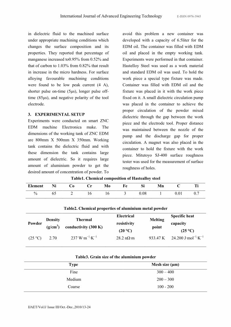
Table1. Chemical composition of Hastealloy steel
Element Ni Co Cr Mo Fe Si Mn C Ti
% 65 2 16 16 3 0.08 1 0.01 0.7
Table2. Chemical properties of aluminium metal powder
Powder Density
(g/cm3)
Thermal
conductivity (300 K)
Electrical
resistivity
(20 °C)
Melting
point
Specific heat
capacity
(25 °C)
(25 °C) 2.70 237 W·m−1·K
−1 28.2 nΩ·m 933.47 K 24.200 J·mol
−1·K
−1
Table3. Grain size of the aluminium powder
Type Mesh size (µm)
Fine 300 – 400
Medium 200 – 300
Coarse 100 - 200

International Journal of Advanced Engineering Technology E-ISSN 0976-3945
IJAET/Vol.I/ Issue III/Oct.-Dec.,2010/13-24
3.1 Experimentation
The experiments were conducted with the
Reverse Polarity on the EDM. Two input
process parameters decided are concentration
of aluminium powder and the grain size of the
powder particles. Output parameters decided
are MRR, TWR, %WR, SR.
Table4. Experimental settings
Polarity Negative (-)
Machining time 20 min.
Electrode lift time 0.2 sec.
Total nine numbers of experiments were
conducted. During the first five experiments
Current, voltage, pulse on time, duty cycle and
grain size was kept at a known constant value
and the concentration of the powder was
changed after certain intervals for different
experiments. In the next four experiments the
concentration of powder was kept constant
along with current, voltage, and pulse on time,
duty cycle and grain size of the powder is
changed for each experiment. Output
parameters were calculated accordingly by
taking necessary observations.
Measurement of Material Removal Rate:
MRR = Work piece weight loss (g)
Machining Time (min)
Measurement of Tool Wear Rate:
TWR = Work piece weight loss (g)
Machining Time (min)
Measurement of % age Wear Rate:
%WR = TWR X 100/MRR
Measurement of Surface Roughness:
The arithmetic surface roughness value (Ra)
was used to measure the surface finish.
Various measurements of roughness were
carried out at the bottom of holes by using
Mitutoyo SJ-400 Surface Roughness tester.
4. RESULTS AND DISCUSSIONS
Total nine numbers of experiments were
performed on hastelloy steel with powder
mixed EDM process using reverse polarity. At
the end of each experiment; calculations were
done for MRR, TWR, Percentage WR, and
SR. The final phase of experimental work has
been analysed and results have been discussed.
The variations of all the four output
parameters have been plotted against the
variable input parameters
Table 5.Parametric variation chart
Exp
No.
Current
(A)
Voltage
(V)
Pulse on
time (µs)
Duty cycle
(µs)
Concentration
(g/lt) Type of powder
1 5 60 150 9 00 Without powder
2 5 60 150 9 03 Medium
3 5 60 150 9 06 Medium
4 5 60 150 9 09 Medium
5 5 60 150 9 12 Medium
6 5 60 150 9 00 Without powder
7 5 60 150 9 06 Fine
8 5 60 150 9 06 Medium
9 5 60 150 9 06 Coarse
.

International Journal of Advanced Engineering Technology E-ISSN 0976-3945
IJAET/Vol.I/ Issue III/Oct.-Dec.,2010/13-24
Table 6.Observation chart
Exp.
No.
Work piece
weight loss
(g)
Electrode
weight
Loss (g)
Time of cut
(min)
MRR
(g/min)
TWR
(g/min) % WR
Ra
(µm)
1 0.006 0.008 20 0.0003 0.0004 133.33 2.13
2 0.064 0.012 20 0.0032 0.0005 18.76 1.97
3 0.082 0.02 20 0.0041 0.001 24.3 1.67
4 0.03 0.01 20 0.0015 0.0005 33.33 1.806
5 0.09 0.018 20 0.0045 0.0009 20 1.43
6 0.006 0.008 20 0.0003 0.0004 133.33 2.13
7 0.06 0.018 20 0.003 0.0009 30 2.87
8 0.082 0.02 20 0.0041 0.001 24.39 1.67
9 0.092 0.019 20 0.0046 0.00095 21.73 1.59
Analysis of Material Removal Rate (MRR)
Fig.1 Graph between concentration and MRR
Fig.2 Graph between grain size of powder and MRR
Concentration
It was seen that material removal rate is very
low in conventional EDM with reverse
polarity. With the addition of aluminium
powder in the dielectric fluid material removal
rate increases sharply. It is because of the fact
that with addition of powder particles in
dielectric, the spark gap is filled up with
additive particles. The powder particles
reduces the insulating strength of dielectric

International Journal of Advanced Engineering Technology E-ISSN 0976-3945
IJAET/Vol.I/ Issue III/Oct.-Dec.,2010/13-24
fluid and increases the spark gap distance
between tool and work piece This increases
the material removal rate with the increase in
concentration. However, with further increase
in concentration, MRR lowers down, it may be
due to short circuiting with increase in powder
density. Again at concentration of 12gm/lt the
value of MRR rises it can be explained by the
fact that with the more powder particles more
erosion from the work piece.
Grain Size of the powder
It was observed that material removal rate is
very low without any grain size of particles.
However, with the addition of fine grain size
of aluminium powder the value of MRR
increases sharply. With future addition of
medium and coarse grain size powder particles
the value of MRR increases, but not as sharp.
This may be defined by the reason that the
density of suspended fine particles is higher
than that of medium and coarse particles.
Analysis of the Tool Wear Rate (TWR)
Fig3. Graph between Concentration and TWR
Fig4. Graph between Grain size of the powder and TWR

International Journal of Advanced Engineering Technology E-ISSN 0976-3945
IJAET/Vol.I/ Issue III/Oct.-Dec.,2010/13-24
Concentration
It was observed that the tool wear rate is more
than the material removal rate with zero
concentration of powder and tool wear rate
increases with the addition of powder particles
in the dielectric. This can be explained by the
fact that during reverse polarity more heat is at
the tool electrode than the work piece. With
the addition of powder concentration in fluid
due to erosion of electrode the tool wear rate
increases. A little change in the trend may be
due to the more erosion of tool at
concentration of 9gm/lt. It may be due to the
reason that higher concentrations of powder
particles block the path of ions to hit the
electrode surface. Again at 12gm/lt
concentration the TWR increases. It may be
due to the reason that at higher concentration
more particles hit the electrode during reverse
polarity.
Grain size of the powder
As per (figure 4) graph between Grain size of
the powder and TWR, it is observed that with
the addition of powder with fine particles the
tool wear rate increases. It is due to the reason
that ions produced by the ionization of
dielectric fluid, hits the tool electrode with
high momentum and high energy during the
reverse polarity setup. And hence more tool
material is eroded.
Analysis of percentage wear rate (%WR)
Fig5 Graph between Concentration and % wear rate
Fig6. Graph between grain size of powder and %wear rate
Concentration

International Journal of Advanced Engineering Technology E-ISSN 0976-3945
IJAET/Vol.I/ Issue III/Oct.-Dec.,2010/13-24
It was observed that the value of percentage
wear rate is high with no powder suspended;
this can be explained that more heat is at the
tool during reverse polarity. As the powder is
suspended in the dielectric the value of MRR
increases more than that of TWR and hence
the value of percentage wear rate decreases
sharply. A little change in trend can be
explained by the fact that tool wear rate
increase due to erosion of tool electrode due to
more concentration of powder particles.
Grain size of the powder
With the change in the grain size of the
powder particles the percentage wear rate
decreases continuously. This can be explained
by the fact that MRR increases with change in
the grain size of the powder particles more
than the increase in the tool wear rate. Hence
decrease in the percentage wear rate.

International Journal of Advanced Engineering Technology E-ISSN 0976-3945
IJAET/Vol.I/ Issue III/Oct.-Dec.,2010/13-24
Concentration
From the graph drawn between the
concentration of the powder & surface
roughness figure7 , it is clear that the value of
surface roughness keeps on decreasing with
increasing the concentration of the powder in
dielectric. This may be explained by the fact
that this improvement in surface quality is due
to the reason that suspended powder particles
enlarge and widen the discharge passage
which helps easy evacuation of produced
debris from the spark gap. The suspended
powder particles lead to uniform dispersion of
discharge energy in all directions, which
results in shallow and small craters on the
machining surfaces. Due to this, surface
roughness reduces. Moreover during reverse
polarity more heat is at the electrode and less
heat is at the work piece. Reverse polarity
helps to attain better surface quality.
Grain size of powder
From the graph drawn between the
concentration of the powder & surface
roughness figure8, it is seen that surface
roughness increases when we add fine powder
particles. This can be explained by the fact that
densities of the fine powder particles are very
high so these particles come in the spark gap
and clog the discharge passage. Because of
this short circuiting takes place and process
became unstable. Moreover not easy
evacuation of debris produced leads to
somewhat rough surface. As we add powder
with medium grain size particles and then
coarse size powder particles the surface
roughness decreases continuously. This can be
explained by the reason that these particles are
not as dense as the fine particles. So these
powder particles easily enlarge and widen the
discharge passage which further facilitates
easy evacuation of produced debris from the
spark gap and lead to uniform dispersion of
discharge energy in all directions. Due to this,
better surface finish is achieved.
5. CONCLUSION
The experimental research work carried out on
reverse polarity on EDM are intended to
contribute to the generation of knowledge
related to the effect of aluminium powder
particles suspended in the EDM dielectric in
the quality of the final surface. The input
parameters have been taken as concentration
of the powder and the grain size of the powder
and the output parameters are MRR, TWR,
Percentage wear rate, Surface roughness.
Within the experimental range following
conclusions can be drawn:
1. The surface roughness of the work
material continuously decreases with the
increase in the concentration of
aluminium powder and with change in
the grain size of the powder particles.
2. With the increase in the concentration of
the powder, percentage wear rate
decreases sharply.
3. With change in the grain size of the
powder, the percentage wear rate
decreases continuously.
4. With the increase in the concentration of
additive powder in the dielectric fluid,
the tool wear increases.
5. With the addition of aluminium powder
in the dielectric fluid of EDM, the
material removal rate increases.
International Journal of Advanced Engineering Technology E-ISSN 0976-3945
IJAET/Vol.I/ Issue III/Oct.-Dec.,2010/13-24
6. With increase in the grain size of the
aluminium powder particles in the
dielectric, the material removal rate
increases continuously.
ACKNOWLEDGEMENTS
The authors would like to acknowledge the
support of the Department of Mechanical
Engineering, Beant College of Engineering
and Technology, Gurdaspur, Punjab, India and
All India Council for Technical Education,
New Delhi, India, for supporting and funding
the research work under research promotion
scheme (F. No.: 8023/BOR/RID/RPS-
129/2007-2008 and F. No.:
8023/BOR/RID/RPS-144/2008 - 2009) in this
direction.
REFERENCES
1. Erden A., Bilgin S. (1980) “Role of
impurities in electric discharge
machining.” Proceedings of 21st
International Machine Tool Design and
Research Conference, pp. 345-350
2. Jeswani ML (1981) “Effect of the addition
of Graphite Powder to Kerosene used as
the dielectric fluid in electrical discharge
Machining” Wear 70 133-139.
3. Narumiya H,Mohri N, Saito N, Ootake H,
Tsunekawa Y, Takawashi T, Kobayashi K
(1989) “EDM by powder suspended
working fluid. Proc Int Sympo Electro-
Machining” IX Japan pp. 5-8
4. Kobayashi K., Magara, T., Ozaki, Y., and
Yatomi, T.(1992) “The present and future
developments of electrical discharge
machining.” In Proceedings of the 2nd
International Conference on Die and
Mould Technology, Singapore pp. 35-47
5. Wong Y S, Lim L C, Rahuman I and Tee
W M (1998) “Near-mirror-finish
phenomenon in EDM using powder-mixed
dielectric.” J. Mater. Process. Technol.
(Switzerland) 79 30–40
6. Furutani K, Saneto A, Takezawa H, Mohri
N, Miyake H (2001) “Accretion of
titanium carbide by electrical discharge
machining with powder suspended in
working fluid.” Precision Engg 25:138–
144
7. Tzeng Y.F., Lee C.Y., (2001) “Effects of
powder characteristics on electro
discharge machining efficiency.”
International Journal of Advanced
Manufacturing Technology, Volume 17,
2001, pp. 586-592
8. Yan BH, Lin YC, Huang FY, Wang CH
(2001) “Surface modification of SKD 61
during EDM with metal powder in the
dielectric.” Mater Trans 42(12):2597–
2604
9. Kozak J, Rozenek M, Dabrowski L (2003)
“Study of electrical discharge machining
using powder-suspended working media.”
Proc Inst Mech Eng Pt B 217(B11):1597–
1602
10. Peças P, Henriques E (2003) “Influence of
silicon powder-mixed dielectric on
conventional electrical discharge
machining.” Int J Mach Tools Manuf
43(14):1465–1471
11. Klocke F, Lung D, Antonoglou G,
Thomaidis D (2004) “The effects of
powder suspended dielectrics on the
thermal influenced zone by
electrodischarge machining with small
discharge energies.” Int J Mater Process
Technol 149:191–197
12. Wu KL, Yan BH, Huang FY, Chen SC
(2005) “Improvement of surface finish on
SKD steel using electro-discharge
machining with aluminium and surfactant
added dielectric.” Int J Mach Tools Manuf
45:1195–1201
13. Kansal H.K.,Singh S, Kumar P. (2005)
“Parametric optimization of powder mixed
electrical discharge machining by
response surface methodology.” Journal of
Materials Processing Technology 169
427–436
14. S H Yeo, P C Tan and W Kurnia (2007)
“Effects of powder additives suspended in
dielectric on crater characteristics for
micro electrical discharge machining.” J.
Micromech. Microeng. 17 N91–N98
15. Peças P, Henriques (2008) “Effect of the
powder concentration and dielectric flow
in the surface morphology in electrical
discharge machining with powder-mixed
dielectric (PMD-EDM)” Int J Adv Manuf
Technol 37:1120–1132
16. Furutani K,Sato H & Suzuki M (2009)
“Influence of electrical conditions on
performance of electrical discharge
machining with powder suspended in
working oil for titanium carbide
deposition process.” Int J Adv Manuf
Technol 40:1093–1101
17. Kumar S & Singh R (2010) “Investigating
surface properties of OHNS die steel after

International Journal of Advanced Engineering Technology E-ISSN 0976-3945
IJAET/Vol.I/ Issue III/Oct.-Dec.,2010/13-24
electrical discharge machining with
manganese powder mixed in the
dielectric.” Int J Adv Manuf Technol DOI
10.1007/s00170-010-2536-3