effect of axial compression on ductility design of rc walls
TRANSCRIPT
Effect of axial compression onductility design of RC walls&1 Y. P. Yuen BEng, PhD
Assistant Professor, Department of Civil Engineering, Bursa OrhangaziÜniversitesi, Bursa, Turkey
&2 J. S. Kuang PhD, CEng, FICE, FIStructE, FHKIEProfessor, Department of Civil and Environmental Engineering,The Hong Kong University of Science and Technology, Hong Kong
1 2
Reinforced concrete (RC) structural walls can render excellent lateral stability and ductility to medium to high-rise
buildings, but are generally subjected to very high axial compression loading, which can reduce the inherent ductility.
A comprehensive statistical analysis with 474 sets of experimental data was conducted to evaluate and quantify the
effect of the axial compression ratio (ACR) on the structural performance of RC structural walls. The stipulated limits
on the ACR and the methods of evaluation used in various design codes were compared. Provisions on the limits of
the ACR stipulated in various design codes were compared, and the expected attainable ductility factors for RC walls
designed to different codes were evaluated. It was found that the provisions on ACR limits in Eurocode 8 generally
satisfy the target ductility level but a distinction needs to be made between non-squat and squat walls due to their
different structural behaviours.
NotationA cross-sectional area of concrete sectionAc gross area of the concrete sectionAg cross-sectional area of a wall segmentAw web area of wallc natural axis depthE seismic actionEci Young’s modulus of unconfined concreteEcl secant modulus from the origin to the peak compres-
sive stressEy Young’s modulus of steel reinforcementfc uniaxial compressive strengths of unconfined
concretef ′c design axial compressive strength of concrete under
uniaxial compression at 28 daysfcc uniaxial compressive strengths of confined concretefcd design cylinder strength (with a safety factor of 1·5)
of concrete under uniaxial compression at 28 daysf ′ck characteristic axial strength of concretefcu characteristic cube strength of concrete under uniax-
ial compression at 28 daysfl effective confining stress provided by the confining
reinforcementfs stress in reinforcement steelfsi stress in the ith reinforcement steelfy uniaxial yield strength of steelGk total permanent or dead load
H height of wallk Eci/Eil
L length of walllp length of plastic hingelw web length of wallM bending momentN axial compressionNED,EC design axial force from the analysis for seismic
designNW,C factored axial force for the wallNW, HK design axial forceQk total live loadQki variable actionrdi combination coefficient for variable action i due to
the representative gravity load (Equation 12)t thickness of wallVp peak shear forcey distance measured from the wall edgeΔg ground displacementΔsp strain penetration effectΔt displacement at the top of the building relative to
the groundΔu ultimate displacementΔy yield displacementαV vertical aspect ratioδu ultimate top displacementδy yield top displacement
554
Structures and BuildingsVolume 168 Issue SB8
Effect of axial compression on ductilitydesign of RC wallsYuen and Kuang
Proceedings of the Institution of Civil EngineersStructures and Buildings 168 August 2015 Issue SB8Pages 554–569 http://dx.doi.org/10.1680/stbu.14.00024Paper 1400024Received 03/03/2014 Accepted 12/02/2015Keywords: codes of practice & standards/concrete structures/statistical analysis
ICE Publishing: All rights reserved
Downloaded by [ HKUST Library] on [01/10/15]. Copyright © ICE Publishing, all rights reserved.
εc concrete compressive strainεcc strain at the peak compressive stress of confined
concreteεc1 strain at the peak compressive stress of unconfined
concreteεcu ultimate crushing strain of concreteεsm rupture strain of steel reinforcementεt strain in the extreme tensile fiberεy steel yielding strainη axial compression ratioμφ curvature ductility factorμΔ displacement ductility factorνn normalised shear strengthρv volumetric ratio of the confinement reinforcementσc compressive stressφp plastic sectional curvatureφu ultimate sectional curvatureφy yield sectional curvatureψE,i combination coefficient (Equation 10)ωv mechanical confining reinforcement ratio
1. IntroductionCatastrophic collapse of reinforced concrete (RC) buildingsclearly necessitates the dragging down of vertical structuralmembers; for instance, the failure of structural walls can lead topotential overall structural instability. In view of this, thecapacity protection of walls and primary columns throughspecial design and detailing is one of the most critical issues inseismic design (fib, 2012; Kappos and Penelis, 1996; Park, 1986;Paulay and Priestley, 1992). It has been demonstrated in manydisastrous earthquakes (Fintel, 1992) that well-designed struc-tural walls can provide excellent lateral stability and drift duct-ility to medium- to high-rise RC buildings under seismic action.
To achieve the goal of capacity design, the enhancement andpreservation of sufficient ductility of RC structural walls areachieved through confinement details, the requirements ofwhich are significantly influenced by the level of the axial forceinduced on the walls. The effect of axial force on the seismic be-haviour of RC walls is actually known from experience, but theforce and behaviour are correlated in many aspects. Althoughthe curvature ductility of RC sections can be readily evaluated atdifferent levels of axial force, the relationships between the axialforce and the buckling tendency of longitudinal reinforcing barsand the cyclic fatigue of the members are quite complicated,especially under seismic loading (Paulay and Priestley, 1992).However, the axial force can also have some positive effect onthe structural behaviour, such as supressing shear sliding andpremature anchorage failure (Kappos and Penelis, 1996). Hencethe actual seismic responses of RC walls under a significantaxial force can be complicated, given that interactions betweendifferent axial force effects and failure mechanisms further com-plicate the situation. Nonetheless, both research studies (Su andWong, 2007; Zhang and Wang, 2000) and disastrous earth-quakes (Adebar, 2013; Wallace et al., 2012) have repeatedly
revealed that the adverse effect of axial compression on RCwalls generally overwhelms the benefits introduced.
The Chile earthquake in 2010 is a good example, showing theeffect of high axial forces on the seismic performance of RCwalls. Post-earthquake field investigations indicated that thinwalls, with thickness ranging from 150 to 200mm and designedto the modern standards, in newly built high-rise buildings weresubjected to higher axial compression than thicker walls in theold buildings, and surprisingly suffered more severe damageduring the earthquake (EERI, 2010). This shows that the use ofreinforcement detailing cannot guarantee desirable seismic per-formance of walls when they are subjected to high axial com-pression. Modern complex structures and super-high-riseskyscrapers, both in Chile and in other parts of the developedworld, are also often characterised by high compression forcesin very slender members, as a consequence of architecturaldesigns that maximise clear floor heights and usable floor areas.Recent studies (Su and Wong, 2006; Wallace et al., 2012) haveindicated that structural walls in modern high-rise buildingswould sustain an axial compression ratio (ACR) of 0·4 or above,which is much higher than the typical range of 0–0·2.
To avert undesirable brittle failures of RC members, on thebasis of the work by Chronopoulos and Vinzileou (1995),Eurocode 8 (BSI, 2004) stipulates the limits for the normalisedaxial force, also known as the ‘axial force ratio’, for RCmembers in various ductility classes, despite the largely scat-tered results (Tassios, 1996). Chinese (MCPRC, 2012) andHong Kong (HKSAR-BD, 2013) design codes impose similarrequirements to Eurocode 8. However, not all modern designcodes, for instance, New Zealand, American and Canadiancodes (ACI, 2011; SNZ, 2006), use the same measure to limitthe ACR in the design of RC structures. There is apparentlyno consensus among the different engineering and researchcommunities on whether limiting the ACR is crucial to theductile or capacity design of RC walls to withstand seismicloading. In view of this, in the present study the effect of theACR on seismic performance of RC structural walls was re-visited and a statistical analysis undertaken in order to compareand discuss the rationale of the relevant provisions in variousdesign codes. The aim was to shed light on the justification ofthe use of ACR in the design of RC walls to determine a suit-able limit to control the seismic performance of RC structures.
2. Failure modes of walls
2.1 Slender wallsFailure modes of walls are governed by the slenderness andaxial compression. It is well recognised that the failure modesand mechanisms of slender and squat walls are very different.Slender walls often fail in the flexural mode, with prominenthorizontal cracks developing in plastic hinges, usually at thebase. Under low axial compression, the collapse of slender wallsis due either to low-cycle fatigue fracture of reinforcement in the
555
Structures and BuildingsVolume 168 Issue SB8
Effect of axial compression on ductilitydesign of RC wallsYuen and Kuang
Downloaded by [ HKUST Library] on [01/10/15]. Copyright © ICE Publishing, all rights reserved.
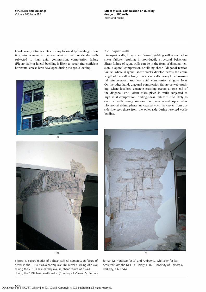
tensile zone, or to concrete crushing followed by buckling of ver-tical reinforcement in the compression zone. For slender wallssubjected to high axial compression, compression failure(Figure 1(a)) or lateral buckling is likely to occur after sufficienthorizontal cracks have developed during the cyclic loading.
2.2 Squat wallsFor squat walls, little or no flexural yielding will occur beforeshear failure, resulting in non-ductile structural behaviour.Shear failure of squat walls can be in the form of diagonal ten-sion, diagonal compression or sliding shear. Diagonal tension
(a)
(b) (c)
Figure 1. Failure modes of a shear wall: (a) compression failure ofa wall in the 1964 Alaska earthquake; (b) lateral buckling of a wallduring the 2010 Chile earthquake; (c) shear failure of a wallduring the 1999 Izmit earthquake. (Courtesy of Vitelmo V. Bertero
for (a), M. Francisco for (b) and Andrew S. Whittaker for (c);acquired from the NISEE e-Library, EERC, University of California,Berkeley, CA, USA)
failure, where diagonal shear cracks develop across the entirelength of the wall, is likely to occur in walls having little horizon-tal reinforcement and low axial compression (Figure 1(c)).On the other hand, diagonal compression failure or web crush-ing, where localised concrete crushing occurs at one end ofthe diagonal strut, often takes place in walls subjected tohigh axial compression. Sliding shear failure is also likely tooccur in walls having low axial compression and aspect ratio.Horizontal sliding planes are created when the cracks from oneside intersect those from the other side during reversed cyclicloading.
556
Structures and BuildingsVolume 168 Issue SB8
Effect of axial compression on ductilitydesign of RC wallsYuen and Kuang
Downloaded by [ HKUST Library] on [01/10/15]. Copyright © ICE Publishing, all rights reserved.
3. Axial compression ratio
3.1 Definition of ACRTo parametrise the axial compression effect on the structuralperformance of RC walls, in the literature the axial com-pression is generally normalised using the concrete uniaxialcompressive strength multiplied by the sectional area of theconcrete member. That is, the ACR η is defined as
1: η ¼ NfcA
where N is the axial compression, fc is uniaxial compressivestrength of concrete, and A is the cross-sectional area of the con-crete section. Besides the confinement detailing, aspect ratios, lapand splices etc., the ACR is a very important factor in evaluatingthe expected ductility and fragility of RC walls during earth-quakes. However, it should not be confused with limit-statedesign concepts, as the ACR alone cannot represent or be usedto assess the actual seismic performance of RC structural walls.
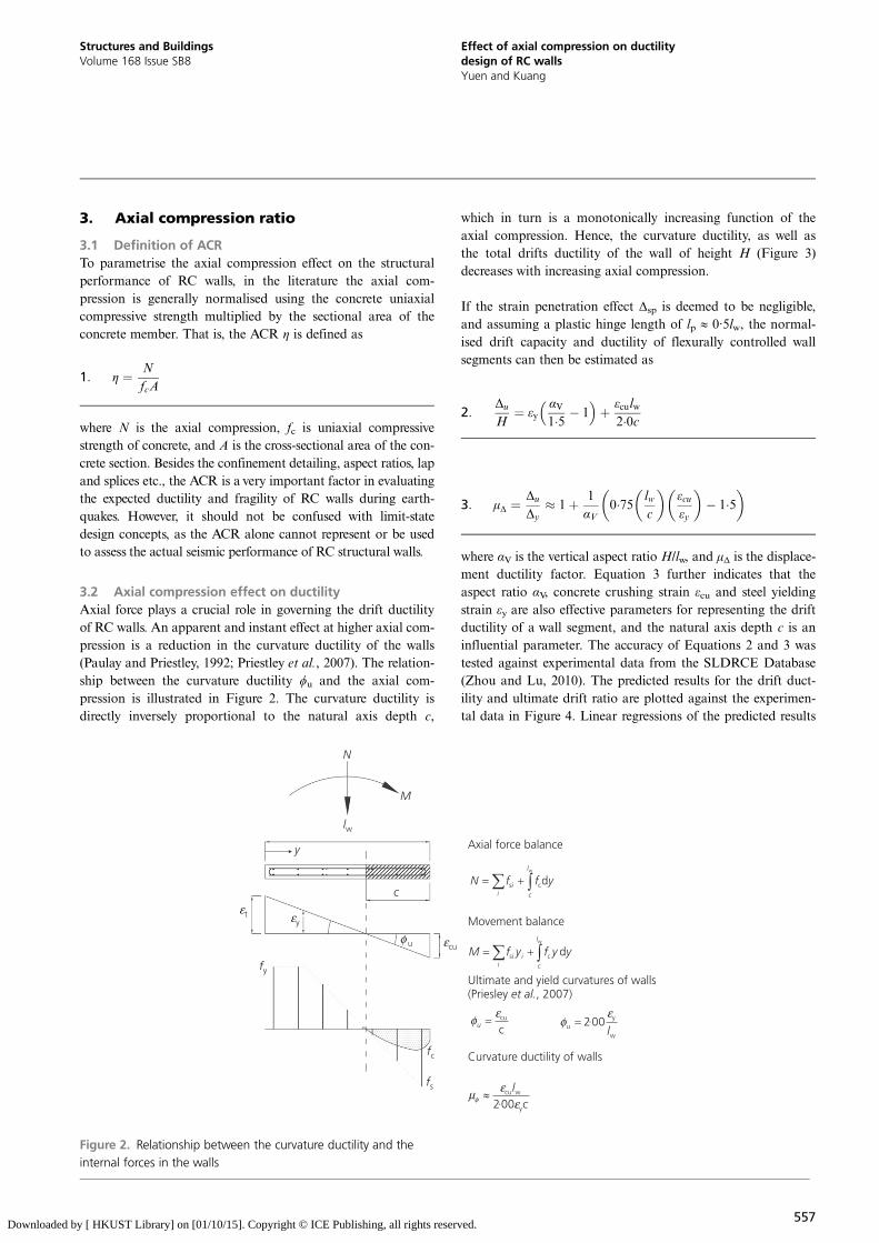
3.2 Axial compression effect on ductilityAxial force plays a crucial role in governing the drift ductilityof RC walls. An apparent and instant effect at higher axial com-pression is a reduction in the curvature ductility of the walls(Paulay and Priestley, 1992; Priestley et al., 2007). The relation-ship between the curvature ductility ϕu and the axial com-pression is illustrated in Figure 2. The curvature ductility isdirectly inversely proportional to the natural axis depth c,
which in turn is a monotonically increasing function of theaxial compression. Hence, the curvature ductility, as well asthe total drifts ductility of the wall of height H (Figure 3)decreases with increasing axial compression.
If the strain penetration effect Δsp is deemed to be negligible,and assuming a plastic hinge length of lp ≈ 0·5lw, the normal-ised drift capacity and ductility of flexurally controlled wallsegments can then be estimated as
2:Δu
H¼ εy
αV1�5 � 1� �
þ εculw2�0c
3: μΔ ¼ Δu
Δy� 1þ 1
αV0�75 lw
c
� �εcuεy
� �� 1�5
� �
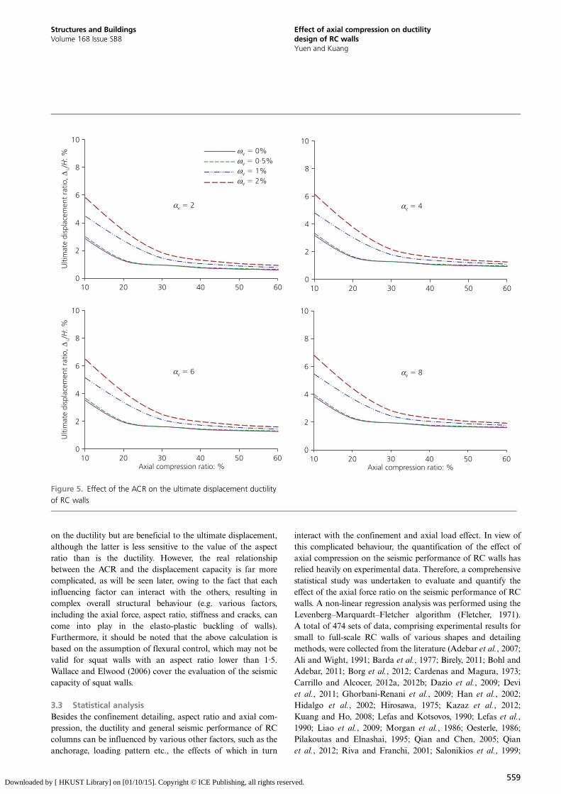
where αV is the vertical aspect ratio H/lw, and μΔ is the displace-ment ductility factor. Equation 3 further indicates that theaspect ratio αV, concrete crushing strain εcu and steel yieldingstrain εy are also effective parameters for representing the driftductility of a wall segment, and the natural axis depth c is aninfluential parameter. The accuracy of Equations 2 and 3 wastested against experimental data from the SLDRCE Database(Zhou and Lu, 2010). The predicted results for the drift duct-ility and ultimate drift ratio are plotted against the experimen-tal data in Figure 4. Linear regressions of the predicted results
N
M
lw
y
c
εt εy
φ u εcu
fy
fc
fs
Axial force balance
s cdwl
ii c
N f f y
cu
cu
εφ y
w
200u l
εφ ·
Movement balance
s c dwl
i ii c
M f y f y y
w
y200cul
cφεµ
ε·
Ultimate and yield curvatures of walls(Priesley , 2007)et al.
Curvature ductility of walls
Figure 2. Relationship between the curvature ductility and theinternal forces in the walls
557
Structures and BuildingsVolume 168 Issue SB8
Effect of axial compression on ductilitydesign of RC wallsYuen and Kuang
Downloaded by [ HKUST Library] on [01/10/15]. Copyright © ICE Publishing, all rights reserved.
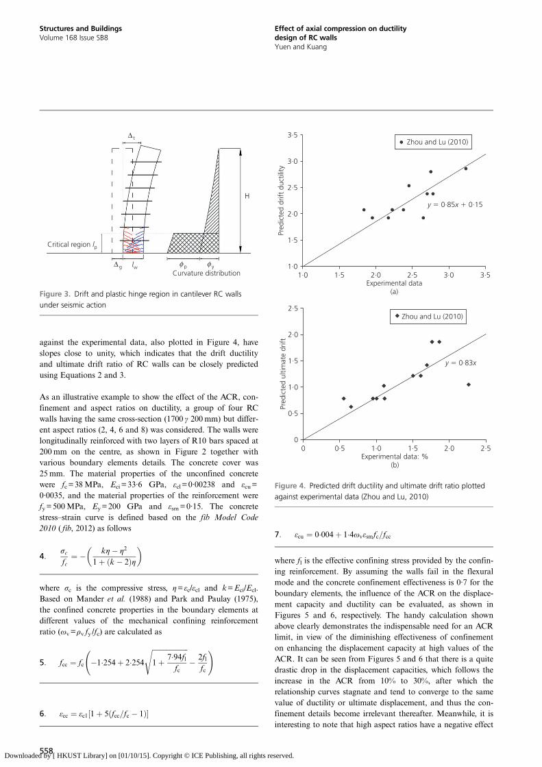
against the experimental data, also plotted in Figure 4, haveslopes close to unity, which indicates that the drift ductilityand ultimate drift ratio of RC walls can be closely predictedusing Equations 2 and 3.
As an illustrative example to show the effect of the ACR, con-finement and aspect ratios on ductility, a group of four RCwalls having the same cross-section (1700 γ 200mm) but differ-ent aspect ratios (2, 4, 6 and 8) was considered. The walls werelongitudinally reinforced with two layers of R10 bars spaced at200mm on the centre, as shown in Figure 2 together withvarious boundary elements details. The concrete cover was25 mm. The material properties of the unconfined concretewere fc=38MPa, Eci=33·6 GPa, εcl=0·00238 and εcu=0·0035, and the material properties of the reinforcement werefy=500MPa, Ey=200 GPa and εsm=0·15. The concretestress–strain curve is defined based on the fib Model Code2010 ( fib, 2012) as follows
4:σcfc
¼ � kη� η2
1þ ðk � 2Þη� �
where σc is the compressive stress, η= εc/εcl and k=Eci/Ecl.Based on Mander et al. (1988) and Park and Paulay (1975),the confined concrete properties in the boundary elements atdifferent values of the mechanical confining reinforcementratio (ωv=ρv fy /fc) are calculated as
5: fcc ¼ fc �1�254þ 2�254ffiffiffiffiffiffiffiffiffiffiffiffiffiffiffiffiffiffiffiffiffi1þ 7�94fl
fc
s� 2fl
fc
!
6: εcc ¼ εc1½1þ 5ðfcc=fc � 1Þ�
7: εcu ¼ 0�004þ 1�4ωvεsmfc=fcc
where fl is the effective confining stress provided by the confin-ing reinforcement. By assuming the walls fail in the flexuralmode and the concrete confinement effectiveness is 0·7 for theboundary elements, the influence of the ACR on the displace-ment capacity and ductility can be evaluated, as shown inFigures 5 and 6, respectively. The handy calculation shownabove clearly demonstrates the indispensable need for an ACRlimit, in view of the diminishing effectiveness of confinementon enhancing the displacement capacity at high values of theACR. It can be seen from Figures 5 and 6 that there is a quitedrastic drop in the displacement capacities, which follows theincrease in the ACR from 10% to 30%, after which therelationship curves stagnate and tend to converge to the samevalue of ductility or ultimate displacement, and thus the con-finement details become irrelevant thereafter. Meanwhile, it isinteresting to note that high aspect ratios have a negative effect
Critical region lp
Curvature distribution∆g lw φ p φ y
H
∆ t
Figure 3. Drift and plastic hinge region in cantilever RC wallsunder seismic action
1·0
1·5
2·0
2·5
3·0
3·5
1·0 1·5 2·0 2·5 3·0 3·5Pr
edic
ted
drift
duc
tility
Experimental data(a)
y x0·85 0·15
Zhou and Lu (2010)
0
0·5
1·0
1·5
2·0
2·5
0 0·5 1·0 1·5 2·0 2·5
Pred
icte
d ul
timat
e dr
ift
Experimental data: %(b)
y x0·83
Zhou and Lu (2010)
Figure 4. Predicted drift ductility and ultimate drift ratio plottedagainst experimental data (Zhou and Lu, 2010)
558
Structures and BuildingsVolume 168 Issue SB8
Effect of axial compression on ductilitydesign of RC wallsYuen and Kuang
Downloaded by [ HKUST Library] on [01/10/15]. Copyright © ICE Publishing, all rights reserved.
on the ductility but are beneficial to the ultimate displacement,although the latter is less sensitive to the value of the aspectratio than is the ductility. However, the real relationshipbetween the ACR and the displacement capacity is far morecomplicated, as will be seen later, owing to the fact that eachinfluencing factor can interact with the others, resulting incomplex overall structural behaviour (e.g. various factors,including the axial force, aspect ratio, stiffness and cracks, cancome into play in the elasto-plastic buckling of walls).Furthermore, it should be noted that the above calculation isbased on the assumption of flexural control, which may not bevalid for squat walls with an aspect ratio lower than 1·5.Wallace and Elwood (2006) cover the evaluation of the seismiccapacity of squat walls.
3.3 Statistical analysisBesides the confinement detailing, aspect ratio and axial com-pression, the ductility and general seismic performance of RCcolumns can be influenced by various other factors, such as theanchorage, loading pattern etc., the effects of which in turn
interact with the confinement and axial load effect. In view ofthis complicated behaviour, the quantification of the effect ofaxial compression on the seismic performance of RC walls hasrelied heavily on experimental data. Therefore, a comprehensivestatistical study was undertaken to evaluate and quantify theeffect of the axial force ratio on the seismic performance of RCwalls. A non-linear regression analysis was performed using theLevenberg–Marquardt–Fletcher algorithm (Fletcher, 1971).A total of 474 sets of data, comprising experimental results forsmall to full-scale RC walls of various shapes and detailingmethods, were collected from the literature (Adebar et al., 2007;Ali and Wight, 1991; Barda et al., 1977; Birely, 2011; Bohl andAdebar, 2011; Borg et al., 2012; Cardenas and Magura, 1973;Carrillo and Alcocer, 2012a, 2012b; Dazio et al., 2009; Deviet al., 2011; Ghorbani-Renani et al., 2009; Han et al., 2002;Hidalgo et al., 2002; Hirosawa, 1975; Kazaz et al., 2012;Kuang and Ho, 2008; Lefas and Kotsovos, 1990; Lefas et al.,1990; Liao et al., 2009; Morgan et al., 1986; Oesterle, 1986;Pilakoutas and Elnashai, 1995; Qian and Chen, 2005; Qianet al., 2012; Riva and Franchi, 2001; Salonikios et al., 1999;
0
2
4
6
8
10
10 20 30 40 50 60
Ulti
mat
e di
spla
cem
ent
ratio
,/
: %∆
uH
αv 2�
ωv 0%�
ωv 0·5%�
ωv 1%�
ωv 2%�
0
2
4
6
8
10
10 20 30 40 50 60
Ulti
mat
e di
spla
cem
ent
ratio
,/
: %∆
uH
Axial compression ratio: %
αv 6�
0
2
4
6
8
10
10 20 30 40 50 60Axial compression ratio: %
αv 8�
0
2
4
6
8
10
10 20 30 40 50 60
αv 4�
Figure 5. Effect of the ACR on the ultimate displacement ductilityof RC walls
559
Structures and BuildingsVolume 168 Issue SB8
Effect of axial compression on ductilitydesign of RC wallsYuen and Kuang
Downloaded by [ HKUST Library] on [01/10/15]. Copyright © ICE Publishing, all rights reserved.

Shiu et al., 1981; Su and Wong, 2007; Takahashi et al., 2013;Thomsen and Wallace, 1995; Vallenas et al., 1979; Wallace andElwood, 2006; Wallace and Moehle, 1991; Wang et al., 1975;Yuen et al., 2004; Zhang and Wang, 2000; Zhou and Lu, 2010).The load–displacement data gathered were then analysed usingdefinitions of yield displacement, ultimate displacement anddisplacement ductility of the loading curves based on the workby Park (1989). In the collected database, more than 60% ofthe tests had been conducted under a relatively low axial forceratio (<0·05), while only about 15% and 7% were tested with anaxial force ratio above 0·15 and 0·30, respectively. Nonetheless,these high axial force tests demonstrated that RC walls will failin a very particular manner, such as out-of-plane buckling,resembling the observed modes of damage to walls seen inthe 2010 Chile earthquake. RC walls that have failed in out-of-plane buckling are generally very brittle and exhibit lowductility, so the classical methods of evaluating ductility, whichassuming in-plane flexural failure, are no longer applicable. Therelationship between the ultimate displacement capacity andthe ACR for various types of RC shear walls having differ-ent aspect ratios H/L is plotted in Figure 7(a). The statistical
analysis followed the design codes in defining the ACR limit,in that no differentiation was made between different types ofwalls. Nonetheless, it is recognised that the failure behaviourof different types of wall can be very different even underthe same ACR. Hence, the data were disaggregated further intotwo groups – squat and non-squat walls – for individual statisti-cal analysis. Similar to the analytical results shown in Figure 4,for slender walls there is a trend of diminishing ultimate dis-placement capacity with increasing ACR (Figure 7(b)), owingto the reduction in the neutral axial depth, the low-cycle fatigueeffect as well as potential out-of-plane buckling.
Conversely, the ultimate displacement capacity of squat wallstends to increase with increasing ACR (Figure 7(c)). Thisreversed trend is actually due to the fact that the shear strengthand sliding resistance of cracks in squat walls are enhanced byaxial compression. Furthermore, it can be seen that the stan-dard deviation varies with the ACR. Such variation is consist-ent with the physical and mechanical behaviour of the walls.When the ACR is low, the failure behaviour can be stronglyinfluenced by the reinforcement detailing, resulting in a large
0
2
4
6
8
10
12
14
16
18
10 20 30 40 50 60
Dis
plac
emen
t du
ctili
ty/
∆∆
uy
αv 2�
ωv 0%�
ωv 0·5%�
ωv 1%�
ωv 2%�
0
2
4
6
8
10
12
14
16
18
10 20 30 40 50 60
Dis
plac
emen
t du
ctili
ty/
∆∆
uy
Axial compression ratio: %
αv 6�
0
2
4
6
8
10
12
14
16
18
10 20 30 40 50 60Axial compression ratio: %
αv 8�
0
2
4
6
8
10
12
14
16
18
10 20 30 40 50 60
αv 4�
Figure 6. Effect of the ACR on the displacement ductility ofRC walls
560
Structures and BuildingsVolume 168 Issue SB8
Effect of axial compression on ductilitydesign of RC wallsYuen and Kuang
Downloaded by [ HKUST Library] on [01/10/15]. Copyright © ICE Publishing, all rights reserved.
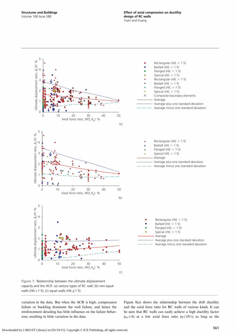
variation in the data. But when the ACR is high, compressionfailure or buckling dominate the wall failure, and hence thereinforcement detailing has little influence on the failure behav-iour, resulting in little variation in the data.
Figure 8(a) shows the relationship between the drift ductilityand the axial force ratio for RC walls of various kinds. It canbe seen that RC walls can easily achieve a high ductility factor(μΔ ≥ 6) at a low axial force ratio (η≤10%) as long as the
0
1
2
3
4
5
0 10 20 30 40 50
Ulti
mat
e di
spla
cem
ent
ratio
,/
: %δ u
H
Axial force ratio, /( ): %N f Ac g
Rectangular ( / 1·5)H LBarbell ( / 1·5)H LFlanged ( / 1·5)H LSpecial ( / 1·5)H LRectangular ( / 1·5)H LBarbell ( / 1·5)H LFlanged ( / 1·5)H LSpecial ( / 1·5)H LComposite boundary elementsAverageAverage plus one standard deviationAverage minus one standard deviation
(a)
0
1
2
3
4
5
0 10 20 30 40 50
Ulti
mat
e di
spla
cem
ent
ratio
,/
: %δ u
H
Axial force ratio, /( ): %N f Ac g
Rectangular ( / 1·5)H LBarbell ( / 1·5)H LFlanged ( / 1·5)H LSpecial ( / 1·5)H LAverageAverage plus one standard deviationAverage minus one standard deviation
0
1
2
3
4
5
0 10 20 30 40 50
Ulti
mat
e di
spla
cem
ent
ratio
,/
: %δ u
H
Axial force ratio, /( ): %N f Ac g
Rectangular ( / 1·5)H LBarbell ( / 1·5)H LFlanged ( / 1·5)H LSpecial ( / 1·5)H LAverageAverage plus one standard deviationAverage minus one standard deviation
(b)
(c)
Figure 7. Relationship between the ultimate displacementcapacity and the ACR: (a) various types of RC wall; (b) non-squatwalls (H/L>1·5); (c) squat walls (H/L≤1·5)
561
Structures and BuildingsVolume 168 Issue SB8
Effect of axial compression on ductilitydesign of RC wallsYuen and Kuang
Downloaded by [ HKUST Library] on [01/10/15]. Copyright © ICE Publishing, all rights reserved.
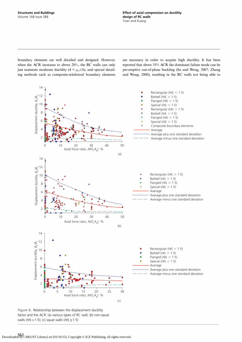
boundary elements are well detailed and designed. However,when the ACR increases to above 20%, the RC walls can onlyjust maintain moderate ductility (4 < μΔ≤6), and special detail-ing methods such as composite-reinforced boundary elements
are necessary in order to acquire high ductility. It has beenreported that above 35% ACR the dominant failure mode can bepre-emptive out-of-plane buckling (Su and Wong, 2007; Zhangand Wang, 2000), resulting in the RC walls not being able to
2
4
6
8
10
12
14
0 10 20 30 40 50
Dis
plac
emen
t du
ctili
ty,
/δ
δu
y
Axial force ratio, /( ): %N f Ac g
Rectangular ( / 1·5)H LBarbell ( / 1·5)H LFlanged ( / 1·5)H LSpecial ( / 1·5)H LRectangular ( / 1·5)H LBarbell ( / 1·5)H LFlanged ( / 1·5)H LSpecial ( / 1·5)H LComposite boundary elementsAverageAverage plus one standard deviationAverage minus one standard deviation
Axial force ratio, /( ): %N f Ac g
2
4
6
8
10
12
14
0 10 20 30 40 50
Dis
plac
emen
t du
ctili
ty,
/δ
δu
y
Rectangular ( / 1·5)H LBarbell ( / 1·5)H LFlanged ( / 1·5)H LSpecial ( / 1·5)H LAverageAverage plus one standard deviationAverage minus one standard deviation
2
4
6
8
10
12
14
Dis
plac
emen
t du
ctili
ty,
/δ
δu
y
Axial force ratio, /( ): %N f Ac g
Rectangular ( / 1·5)H LBarbell ( / 1·5)H LFlanged ( / 1·5)H LSpecial ( / 1·5)H LAverageAverage plus one standard deviationAverage minus one standard deviation
(a)
(b)
(c)
0 5 10 15 20 25 30
Figure 8. Relationship between the displacement ductilityfactor and the ACR: (a) various types of RC wall; (b) non-squatwalls (H/L>1·5); (c) squat walls (H/L≤1·5)
562
Structures and BuildingsVolume 168 Issue SB8
Effect of axial compression on ductilitydesign of RC wallsYuen and Kuang
Downloaded by [ HKUST Library] on [01/10/15]. Copyright © ICE Publishing, all rights reserved.
provide lateral and vertical resistance in seismic design. It isrecognised that squat RC walls with aspect ratios (H/L) lowerthan 1·5 will be prone to shear failure, in particular sliding shearfailure (rather than flexural failure), but the displacement duct-ility is not necessarily reduced by the increase in axial com-pression. In contrast to non-squat walls (Figure 8(b)), theductility of squat walls is less influenced by the ACR and theductility factors generally stay within the range 2 < μΔ≤4, asshown in Figure 8(c). For shear-controlled walls, little or no flex-ural yielding will occur before shear failure (Wallace andElwood, 2006). On the one hand, high axial compression cansuppress the flexural yielding, and hence reduce the ductility ofsquat walls. On the other hand, axial compression can increasethe shear friction on the crack faces in the walls (Wallace andElwood, 2006), favouring the overall behaviour and ultimate driftcapacity of the walls. Hence, the drift ductility – ACR and driftcapacity – ACR relationships show different trends, as can beseen in Figures 7(c) and 8(c).
Another important structural property of RC walls related tothe axial compression is the shear strength. For comparisonpurposes, the peak base shears reported for the tests includedin the database were further normalised using
8: νn ¼ Vp
f 0�5c Aw
where Aw is web area of the wall. Figure 9 shows the relation-ship between the normalised shear strength and the ACR.Higher axial compression tends to increase the shear strengthof all types of RC walls, in particular squat RC walls, asshown in Figure 9(c). This is because axial compression canenhance not only the shear strength of walls but in some casesalso the moment resistance (Kappos and Penelis, 1996;Wallace et al., 2012).
4. Code provisions for the ACRIn view of the adverse effect of axial compression on theseismic performance of RC structural walls (as illustrated inthe last section), most of the modern design codes of practicefor RC structures stipulate upper limits of the ACR. RC wallswith an ACR beyond the limits are generally deemed to beineffective in resisting seismic action, even with confinementdetailing in the critical regions (expected plastic hinges) of themembers. The aim of these provisions, in addition to confine-ment detailing, is to ensure that sufficient drift ductility andaxial force carrying capacity can be retained in RC structuresduring earthquakes or other exceptional load cases.
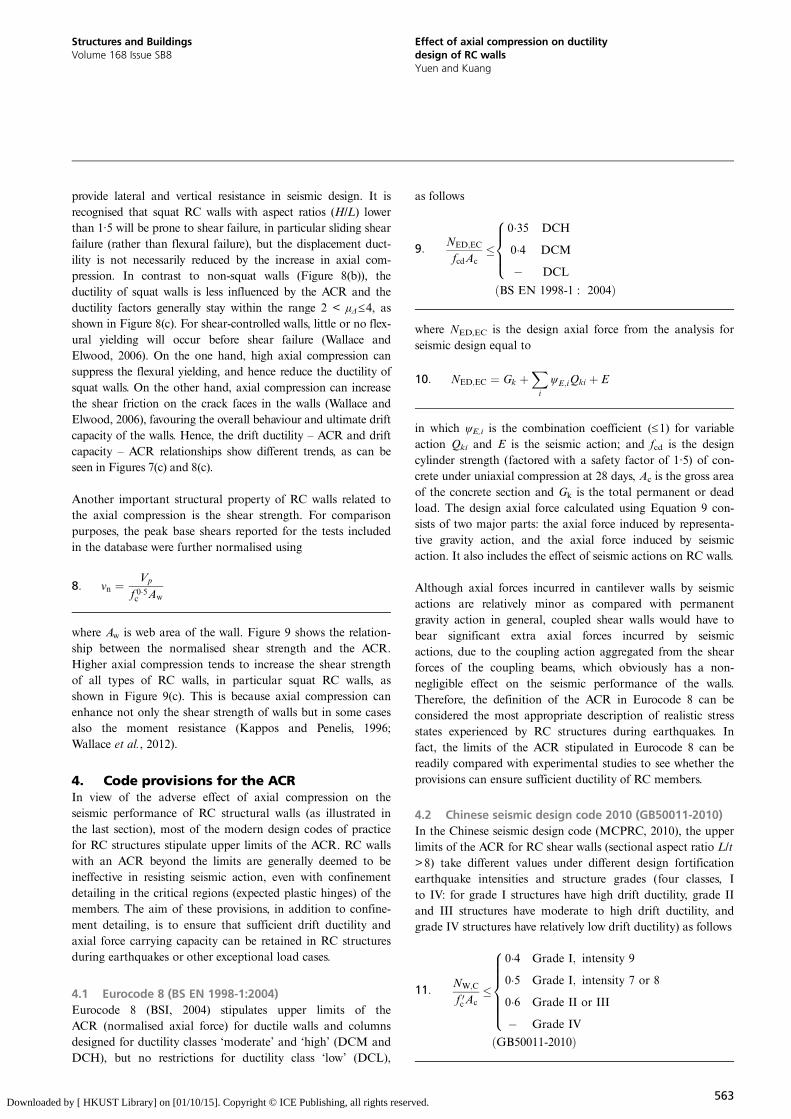
4.1 Eurocode 8 (BS EN 1998-1:2004)Eurocode 8 (BSI, 2004) stipulates upper limits of theACR (normalised axial force) for ductile walls and columnsdesigned for ductility classes ‘moderate’ and ‘high’ (DCM andDCH), but no restrictions for ductility class ‘low’ (DCL),
as follows
9: NED;EC
fcdAc�
0�35 DCH
0�4 DCM
� DCL
8>><>>:ðBS EN 1998-1 : 2004Þ
where NED,EC is the design axial force from the analysis forseismic design equal to
10: NED;EC ¼ Gk þXi
ψE;iQki þ E
in which ψE,i is the combination coefficient (≤1) for variableaction Qki and E is the seismic action; and fcd is the designcylinder strength (factored with a safety factor of 1·5) of con-crete under uniaxial compression at 28 days, Ac is the gross areaof the concrete section and Gk is the total permanent or deadload. The design axial force calculated using Equation 9 con-sists of two major parts: the axial force induced by representa-tive gravity action, and the axial force induced by seismicaction. It also includes the effect of seismic actions on RC walls.
Although axial forces incurred in cantilever walls by seismicactions are relatively minor as compared with permanentgravity action in general, coupled shear walls would have tobear significant extra axial forces incurred by seismicactions, due to the coupling action aggregated from the shearforces of the coupling beams, which obviously has a non-negligible effect on the seismic performance of the walls.Therefore, the definition of the ACR in Eurocode 8 can beconsidered the most appropriate description of realistic stressstates experienced by RC structures during earthquakes. Infact, the limits of the ACR stipulated in Eurocode 8 can bereadily compared with experimental studies to see whether theprovisions can ensure sufficient ductility of RC members.
4.2 Chinese seismic design code 2010 (GB50011-2010)In the Chinese seismic design code (MCPRC, 2010), the upperlimits of the ACR for RC shear walls (sectional aspect ratio L/t>8) take different values under different design fortificationearthquake intensities and structure grades (four classes, Ito IV: for grade I structures have high drift ductility, grade IIand III structures have moderate to high drift ductility, andgrade IV structures have relatively low drift ductility) as follows
11: NW;C
f 0cAc�
0�4 Grade I; intensity 9
0�5 Grade I; intensity 7 or 8
0�6 Grade II or III
� Grade IV
8>>>>><>>>>>:ðGB50011-2010Þ
563
Structures and BuildingsVolume 168 Issue SB8
Effect of axial compression on ductilitydesign of RC wallsYuen and Kuang
Downloaded by [ HKUST Library] on [01/10/15]. Copyright © ICE Publishing, all rights reserved.

0
0·2
0·4
0·6
0·8
1·0
1·2
1·4
1·6
1·8
0 10 20 30 40 50
Nor
mal
ised
she
ar s
tren
gth,
/()
Vf
Ap
c0·5
w
Axial force ratio, /( ): %N f Ac g
Rectangular ( / 1·5)H LBarbell ( / 1·5)H LFlanged ( / 1·5)H LSpecial ( / 1·5)H LRectangular ( / 1·5)H LBarbell ( / 1·5)H LFlanged ( / 1·5)H LSpecial ( / 1·5)H LComposite boundary elementsAverageAverage plus one standard deviationAverage minus one standard deviation
0
0·2
0·4
0·6
0·8
1·0
1·2
1·4
1·6
1·8
0 10 20 30 40 50
Nor
mal
ised
she
ar s
tren
gth,
/(V
fA
pc0·
5w)
Axial force ratio, /( ): %N f Ac g
Rectangular ( / 1·5)H LBarbell ( / 1·5)H LFlanged ( / 1·5)H LSpecial ( / 1·5)H LAverageAverage plus one standard deviationAverage minus one standard deviation
0
0·2
0·4
0·6
0·8
1·0
1·2
1·4
1·6
1·8
Nor
mal
ised
she
ar s
tren
gth,
/(V
fA
pc0·
5w)
Axial force ratio, /( ): %N f Ac g
Rectangular ( / 1·5)H LBarbell ( / 1·5)H LFlanged ( / 1·5)H LSpecial ( / 1·5)H LAverageAverage plus one standard deviationAverage minus one standard deviation
(a)
(b)
(c)
0 5 10 15 20 25 30
Figure 9. Relationship between the normalised shear strengthand the ACR: (a) various types of RC wall; (b) non-squat walls(H/L>1·5); (c) squat walls (H/L≤1·5)
564
Structures and BuildingsVolume 168 Issue SB8
Effect of axial compression on ductilitydesign of RC wallsYuen and Kuang
Downloaded by [ HKUST Library] on [01/10/15]. Copyright © ICE Publishing, all rights reserved.
where NW,C is the factored axial force for the wall equal to
12: NW;C ¼ 1�2ðGk þXi
rdi QkiÞ
in which rdi is the combination coefficient (≤1) for variableaction i due to the representative gravity load, and f ′c is thedesign axial compressive strength of concrete under uniaxialcompression at 28 days (equal to the characteristic axialstrength of concrete f ′ck divided by the safety factor 1·4).
The characteristic axial strength f ′ck is determined in a150�150�300mm prism compression test, which in this codecan be conservatively taken as 0·67 of the characteristic cubestrength fcu,k. The average value of the ratio f ′ck/f cu,k, the so-called ‘effectiveness factor’, is around 0·76, based on experimen-tal studies (Nielsen, 1999; Zhang, 1993). More stringentprovisions are set for short-pier RC shear walls (4<L/t≤8),such that the values of the ACR for grades I, II and III short-pier walls should not exceed 0·45, 0·50 and 0·55, respectively,in the critical regions (MCPRC, 2012). The axial force inEquation 11 is calculated using the representative gravityaction, rather than the ultimate gravity action, which the struc-ture is expected to take during earthquakes, and the multiply-ing factor of 1·2 is used to account for additional axial forceincurred by unforeseen and excluded actions on the walls. Inthe calculation of the representative gravity action, the combi-nation coefficient rdi is used to consider the reduced likelihoodthat full variable actions are present during earthquakes; forinstance, rdi for a residential floor live load is 0·5.
4.3 Hong Kong concrete code 2013In the Hong Kong concrete code (HKSAR-BD, 2013), theupper limit of the ACR for RC structural walls is specified asfollows
13:NW;HK
0�45fcuAc� 0�75
where NW, HK is the design axial force equal to
14: NW;HK ¼ 1�4Gk þ 1�6Qk
in which Gk is the total permanent or dead load and Qk is thetotal live load, for the wall due to gravity load; fcu is thecharacteristic cube strength of concrete under uniaxial com-pression at 28 days, and Ac is the gross area of the concretesection. Note that the safety factor for the concrete compres-sive strength used in the HK code is 1·5, and dividing thecharacteristic concrete strength by this factor gives the designstrength. The constant 0·45=0·67/1·5 in the denominator con-verts the characteristic concrete strength into the equivalentdesign compressive strength for the sections subjected to domi-nant flexural bending action, wherefore another multiplying
factor 0·67 is used. Meanwhile, the axial force in the numer-ator takes the ultimate load value due to sole gravity action,without consideration of possible non-permanent live loadreduction or representative gravity action during rare eventswith exceptional loading actions such as earthquakes.
4.4 New Zealand and other design codesThe New Zealand concrete code (SNZ, 2006) does not havesimilar provisions regarding the axial force ratios as in theEuropean, Chinese and Hong Kong codes, but limiting sec-tional curvatures or strains in potential plastic hinge regionsare specified for different RC members (clause 2.6.1.3.4, NZS3101.1&2:2006). Limiting material strains is apparently themost direct method to control curvature dualities of RCmembers; however, whether it is sufficient to prevent the low-cycle fatigue phenomenon or rapid strength and stiffnessdegradation of RC members under cyclic loading is uncertain.
It is also worth mentioning here that the US concrete designcode ACI 318-11:2011 (ACI, 2011) also does not introducesimilar limits on the ACR for RC columns and walls.Nevertheless, a US standard for the seismic rehabilitation ofbuildings, ASCE/SEI 41-06:2007 (ASCE, 2007; Park, 1989),states that RC walls with axial loads greater than 35% of thenominal axial load strength P0 shall not be considered effectivein resisting seismic forces. The Canadian concrete code, CSAA23.3-04 (CSA, 2010), also states that flexural members withfactored axial loads in excess of 0·35 P0 shall have a nominalresistance greater than the induced member force, (i.e. not tobe designed to form potential plastic hinges and dissipateenergy in any circumstances under seismic effects).
4.5 Comparison of code provisionsAlthough the definitions of the axial force ratios in theEuropean, Chinese and Hong Kong codes are somewhat dis-similar, particularly with regard to the axial forces in thenumerators, the compressive strength terms in the denomi-nators can be readily transformed to give a characteristiccylindrical strength fc=0·8fcu= fcd/1·5 for comparison pur-poses. Table 1 summarises the key comparisons of theprovisions on the ACR defined in the three codes.
The ACR limits stipulated in the Chinese code resemble thosein Eurocode 8 but, as mentioned before, the combinations ofactions for calculating the axial forces are different in the twocodes. For cantilever walls, the Chinese code is more stringentbecause a safety factor of 1·2 is used to amplify the action.However, for coupled shear walls, it is not conclusive which ofthe two codes is more conservative, as the factor of 1·2 maynot be sufficient to cover the exceeding axial forces induced bythe coupling action.
Nevertheless, Eurocode 8 provides a more realistic assessmentfor these cases by taking into consideration seismic or gener-ally lateral force effects. At first sight, looking at the last row
565
Structures and BuildingsVolume 168 Issue SB8
Effect of axial compression on ductilitydesign of RC wallsYuen and Kuang
Downloaded by [ HKUST Library] on [01/10/15]. Copyright © ICE Publishing, all rights reserved.
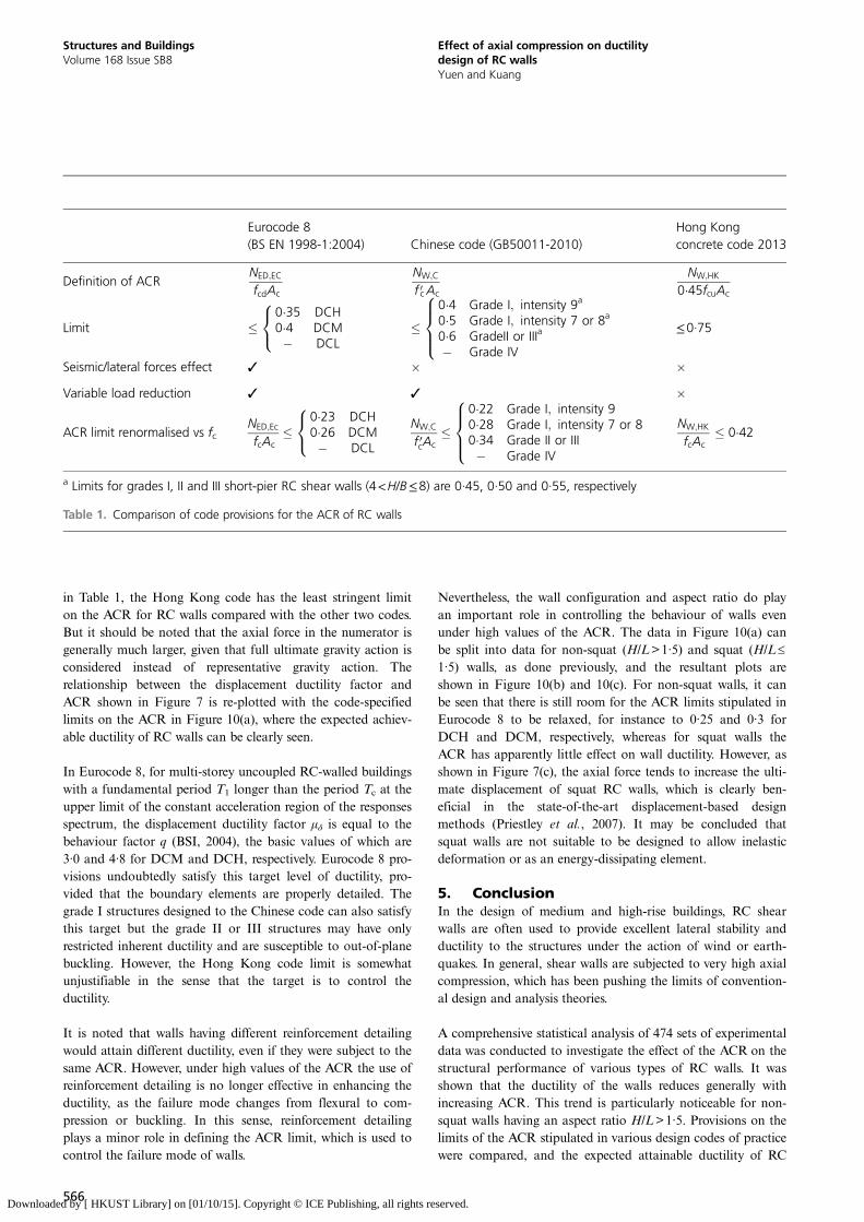
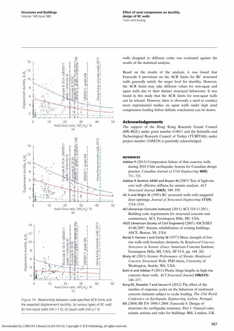
in Table 1, the Hong Kong code has the least stringent limiton the ACR for RC walls compared with the other two codes.But it should be noted that the axial force in the numerator isgenerally much larger, given that full ultimate gravity action isconsidered instead of representative gravity action. Therelationship between the displacement ductility factor andACR shown in Figure 7 is re-plotted with the code-specifiedlimits on the ACR in Figure 10(a), where the expected achiev-able ductility of RC walls can be clearly seen.
In Eurocode 8, for multi-storey uncoupled RC-walled buildingswith a fundamental period T1 longer than the period Tc at theupper limit of the constant acceleration region of the responsesspectrum, the displacement ductility factor μδ is equal to thebehaviour factor q (BSI, 2004), the basic values of which are3·0 and 4·8 for DCM and DCH, respectively. Eurocode 8 pro-visions undoubtedly satisfy this target level of ductility, pro-vided that the boundary elements are properly detailed. Thegrade I structures designed to the Chinese code can also satisfythis target but the grade II or III structures may have onlyrestricted inherent ductility and are susceptible to out-of-planebuckling. However, the Hong Kong code limit is somewhatunjustifiable in the sense that the target is to control theductility.
It is noted that walls having different reinforcement detailingwould attain different ductility, even if they were subject to thesame ACR. However, under high values of the ACR the use ofreinforcement detailing is no longer effective in enhancing theductility, as the failure mode changes from flexural to com-pression or buckling. In this sense, reinforcement detailingplays a minor role in defining the ACR limit, which is used tocontrol the failure mode of walls.
Nevertheless, the wall configuration and aspect ratio do playan important role in controlling the behaviour of walls evenunder high values of the ACR. The data in Figure 10(a) canbe split into data for non-squat (H/L>1·5) and squat (H/L≤
1·5) walls, as done previously, and the resultant plots areshown in Figure 10(b) and 10(c). For non-squat walls, it canbe seen that there is still room for the ACR limits stipulated inEurocode 8 to be relaxed, for instance to 0·25 and 0·3 forDCH and DCM, respectively, whereas for squat walls theACR has apparently little effect on wall ductility. However, asshown in Figure 7(c), the axial force tends to increase the ulti-mate displacement of squat RC walls, which is clearly ben-eficial in the state-of-the-art displacement-based designmethods (Priestley et al., 2007). It may be concluded thatsquat walls are not suitable to be designed to allow inelasticdeformation or as an energy-dissipating element.
5. ConclusionIn the design of medium and high-rise buildings, RC shearwalls are often used to provide excellent lateral stability andductility to the structures under the action of wind or earth-quakes. In general, shear walls are subjected to very high axialcompression, which has been pushing the limits of convention-al design and analysis theories.
A comprehensive statistical analysis of 474 sets of experimentaldata was conducted to investigate the effect of the ACR on thestructural performance of various types of RC walls. It wasshown that the ductility of the walls reduces generally withincreasing ACR. This trend is particularly noticeable for non-squat walls having an aspect ratio H/L>1·5. Provisions on thelimits of the ACR stipulated in various design codes of practicewere compared, and the expected attainable ductility of RC
Eurocode 8(BS EN 1998-1:2004) Chinese code (GB50011-2010)
Hong Kongconcrete code 2013
Definition of ACRNED;EC
fcdAc
NW;C
f 0cAc
NW;HK
0�45fcuAc
Limit �0�35 DCH0�4 DCM� DCL
8<: �
0�4 Grade I; intensity 9a
0�5 Grade I; intensity 7 or 8a
0�6 GradeII or IIIa
� Grade IV
8>><>>: ≤0·75
Seismic/lateral forces effect 3 � �Variable load reduction 3 3 �
ACR limit renormalised vs fcNED;Ec
fcAc�
0�23 DCH0�26 DCM� DCL
8<: NW;C
f 0cAc�
0�22 Grade I; intensity 90�28 Grade I; intensity 7 or 80�34 Grade II or III� Grade IV
8>><>>:
NW;HK
fcAc� 0�42
a Limits for grades I, II and III short-pier RC shear walls (4<H/B≤8) are 0·45, 0·50 and 0·55, respectively
Table 1. Comparison of code provisions for the ACR of RC walls
566
Structures and BuildingsVolume 168 Issue SB8
Effect of axial compression on ductilitydesign of RC wallsYuen and Kuang
Downloaded by [ HKUST Library] on [01/10/15]. Copyright © ICE Publishing, all rights reserved.
walls designed to different codes was evaluated against theresults of the statistical analysis.
Based on the results of the analysis, it was found thatEurocode 8 provisions on the ACR limits for RC structuralwalls generally satisfy the target level for ductility. However,the ACR limits may take different values for non-squat andsquat walls due to their distinct structural behaviours. It wasfound in this study that the ACR limits for non-squat wallscan be relaxed. However, there is obviously a need to conductmore experimental studies on squat walls under high axialcompression loading before definite conclusions can be drawn.
AcknowledgementsThe support of the Hong Kong Research Grand Council(HK-RGC) under grant number 614011 and the Scientific andTechnological Research Council of Turkey (TÜBITAK) underproject number 214M236 is gratefully acknowledged.
REFERENCES
Adebar P (2013) Compression failure of thin concrete wallsduring 2010 Chile earthquake: lessons for Canadian designpractice. Canadian Journal of Civil Engineering 40(8):711–721.
Adebar P, Ibrahim AMM and Bryson M (2007) Test of high-risecore wall: effective stiffness for seismic analysis. ACIStructural Journal 104(5): 549–559.
Ali A and Wight JK (1991) RC structural walls with staggereddoor openings. Journal of Structural Engineering 117(5):1514–1531.
ACI (American Concrete Institute) (2011) ACI 318-11:2011:Building code requirements for structural concrete andcommentary. ACI, Farmington Hills, MI, USA.
ASCE (American Society of Civil Engineers) (2007) ASCE/SEI41-06:2007: Seismic rehabilitation of existing buildings.ASCE, Reston, VA, USA.
Barda F, Hanson J and Corley W (1977) Shear strength of low-rise walls with boundary elements. In Reinforced ConcreteStructures in Seismic Zones. American Concrete Institute,Farmington Hills, MI, USA, SP 53-8, pp. 149–201.
Birely AC (2011) Seismic Performance of Slender ReinforcedConcrete Structural Walls. PhD thesis, University ofWashington, Seattle, WA, USA.
Bohl A and Adebar P (2011) Plastic hinge lengths in high-riseconcrete shear walls. ACI Structural Journal 108(S15):148–157.
Borg RC, Rossetto T and Varum H (2012) The effect of thenumber of response cycles on the behaviour of reinforcedconcrete elements subject to cyclic loading. The 15th WorldConference on Earthquake Engineering, Lisbon, Portugal.
BSI (2004) BS EN 1998-1:2004: Eurocode 8: Design ofstructures for earthquake resistance. Part 1: General rules,seismic actions and rules for buildings. BSI, London, UK.
2
4
6
8
10
12
14
0 10 20 30 4 0
Dis
plac
emen
t du
ctili
ty,
/δ
δu
y
Axial force ratio, /( ): %(a)
N f Ac g
Euro
code
8: D
CH
. GB5
0011
:gr
ade
1 (in
tens
ity 9
)
Euro
code
8: D
CM
GB5
0011
: gra
de 1
(int
ensi
ty 7
/8)
GB5
0011
: gra
de II
/III
Hon
g K
ong
conc
rete
cod
e 20
13
2
4
6
8
10
12
14
0 10 20 30 40 50
Dis
plac
emen
t du
ctili
ty,
/δ
δu
y
Axial force ratio, /( ): %(b)
N f Ac g
Euro
code
8: D
CH
. GB5
0011
:gr
ade
1 (in
tens
ity 9
)
Euro
code
8: D
CM
GB5
0011
: gra
de 1
(int
ensi
ty 7
/8)
GB5
0011
: gra
de II
/III
Hon
g K
ong
conc
rete
cod
e 20
13
2
4
6
8
10
12
14
0 10 20 30 4
0 5
0 50
Dis
plac
emen
t du
ctili
ty,
/δ
δu
y
Axial force ratio, /( ): %(c)
N f Ac g
Euro
code
8: D
CH
. GB5
0011
:gr
ade
1 (in
tens
ity 9
)
Euro
code
8: D
CM
GB5
0011
: gra
de 1
(int
ensi
ty 7
/8)
GB5
0011
: gra
de II
/III
Hon
g K
ong
conc
rete
cod
e 20
13
Figure 10. Relationship between code-specified ACR limits andthe expected displacement ductility: (a) various types of RC wall;(b) non-squat walls (H/L>1·5); (c) squat walls (H/L≤1·5)
567
Structures and BuildingsVolume 168 Issue SB8
Effect of axial compression on ductilitydesign of RC wallsYuen and Kuang
Downloaded by [ HKUST Library] on [01/10/15]. Copyright © ICE Publishing, all rights reserved.
Cardenas AE and Magura DD (1973) Strength of high-rise shearwalls – rectangular cross sections.In Response of MultistoryConcrete Structures to Lateral Forces. American ConcreteInstitute, Farmington Hills, MI, USA, SP-36, pp. 119–150.
Carrillo J and Alcocer SM (2012a) Acceptance limits forperformance-based seismic design of RC walls for low-risehousing. Earthquake Engineering & Structural Dynamics 41(15): 2273–2288.
Carrillo J and Alcocer SM (2012b) Backbone model forperformance-based seismic design of RC walls for low-risehousing. Earthquake Spectra 28(3): 943–964.
Chronopoulos MP and Vinzileou E (1995) Confinement of RCcolumns. In European Seismic Design Practice (ElnashaiAS (ed.)). Balkema, Rotterdam, the Netherlands pp.341–348.
CSA (Canadian Standard Association) (2010) CSA:A23.3-04(R2010): Design of concrete structures. CSA, Ontario,Canada.
Dazio A, Beyer K and Bachmann H (2009) Quasi-static cyclictests and plastic hinge analysis of RC structural walls.Engineering Structures 31(7): 1556–1571.
Devi GN, Subramanian K and Santakumar AR (2011)Experimental investigations on reinforced concrete lateralload resisting systems under lateral loads. ExperimentalTechniques 35(4): 59–73.
EERI (Earthquake Engineering Research Institute) (2010)Learning from Earthquakes. The Mw 8·8 Chile Earthquakeof February 27, 2010. EERI, Oakland, CA, USA,Special Earthquake Report.
fib (Fédération Internationale Du Béton) (2012) Model Code2010 Bulletin 66. fib, Lausanne, Switzerland, vol. 2.
Fintel M (1992) Need for shear walls in concrete buildings forseismic resistance: observations on the performance ofbuildings with shear walls in earthquakes of the last thirtyyears. In Concrete Shear in Earthquake (Hsu TTC andMau ST (eds)). Elsevier, London, UK, pp. 34–42.
Fletcher R (1971) A Modified Marquardt Subroutine forNonlinear Least Squares. United Kingdom Atomic EnergyAuthority, Harwell, UK, Report AERE-R 6799.
Ghorbani-Renani I, Velev N, Tremblay R et al. (2009) Modelingand testing influence of scaling effects on inelastic responseof shear walls. ACI Structural Journal 106(3): 358–367.
Han SW, Oh YH and Lee LH (2002) Seismic behaviour ofstructural walls with specific details. Magazine of ConcreteResearch 54(5): 333–345.
Hidalgo PA, Ledezma CA and Jordan RM (2002) Seismicbehavior of squat reinforced concrete shear walls.Earthquake Spectra 18(2): 287–308.
Hirosawa M (1975) Past Experimental Results onReinforced Concrete Shear Walls and Analysis on Them.Building Research Institute, Ministry of Construction,Tokyo, Japan, Kenchiku Kenkyu Shiryo No. 6(in Japanese).
HKSAR-BD (Government of the Hong Kong Special
Administrative Region – Buildings Department) (2013)
Code of Practice for Structural Use of Concrete 2013.HKSAR-BD, Hong Kong.
Kappos A and Penelis GG (1996) Earthquake Resistant ConcreteStructures. CRC Press, Boca Raton, FL, USA.
Kazaz I, Gülkan P and Yakut A (2012) Deformation limits forstructural walls with confined boundaries. EarthquakeSpectra 28(3): 1019–1046.
Kuang JS and Ho YB (2008) Seismic behavior and ductility ofsquat reinforced concrete shear walls with nonseismicdetailing. ACI Structural Journal 105(2): 225–231.
Lefas ID and Kotsovos MD (1990) Strength and deformationcharacteristics of reinforced concrete walls under loadreversals. ACI Structural Journal 87(6): 716–726.
Lefas ID, Kotsovos MD and Ambrasseys NN (1990) Behaviour ofRC structural walls: strength, deformation characteristicsand failure mechanism. ACI Structural Journal 87(1):23–31.
Liao FY, Han LH and Tao Z (2009) Seismic behaviour of circularCFST columns and RC shear wall mixed structures:experiments. Journal of Constructional Steel Research65(8–9): 1582–1596.
Mander JB, Priestley MJN and Park P (1988) Theoreticalstress–strain model for confined concrete. Journal ofStructural Engineering 114(8): 1804–1826.
Morgan BJ, Hiraishi H and Corley WG (1986) US–Japan QuasiStatic Test of Isolated Wall Planar Reinforced ConcreteStructure. PCA Report. Construction Technology Division,Skokie, IL, USA.
Nielsen MP (1999) Limit Analysis and Concrete Plasticity,2nd edn. CRC Press, Boca Raton, FL, USA.
MCPRC (Ministry of Construction of the People’s Republic of
China) (2010) National Standard of People’s Republic ofChina: Code for seismic design of buildings. ChinaArchitecture & Building Press, Beijing, China, GB50011-2010.
Oesterle RG (1986) Inelastic Analysis for In-plane Strength ofReinforced Concrete Shear Walls. PhD dissertation,Northwestern University, Evanston, IL, USA.
Park R (1986) Ductile design approach for reinforced concreteframes. Earthquake Spectra 2(3): 565–679.
Park R (1989) Evaluation of ductility of structures andstructural assemblages from laboratory testing. Bulletin ofthe New Zealand Society for Earthquake Engineering 22(3):155–166.
Park R and Paulay T (1975) Reinforced Concrete Structures.Wiley, New York, NY, USA.
Paulay T and Priestley MJN (1992) Seismic Design of ReinforcedConcrete and Masonry Buildings. Wiley, New York, NY,USA.
Pilakoutas K and Elnashai AS (1995) Cyclic behaviour of RCcantilever walls. Part I: experimental results. ACI StructuralJournal 92(3): 271–281.
Priestley MJN, Calvi GM and Kowalsky MJ (2007)Displacement-Based Seismic Design of Structures.IUSS Press, Pavia, Italy.
568
Structures and BuildingsVolume 168 Issue SB8
Effect of axial compression on ductilitydesign of RC wallsYuen and Kuang
Downloaded by [ HKUST Library] on [01/10/15]. Copyright © ICE Publishing, all rights reserved.
Qian J and Chen Q (2005) A macro model of shear walls forpush-over analysis. Proceedings of the ICE – Structuresand Buildings 158(2): 119–132.
Qian J, Jiang Z and Ji X (2012) Behavior of steeltube-reinforced concrete composite walls subjected tohigh axial force and cyclic loading. Engineering Structures36(3): 173–184.
Riva P and Franchi A (2001) Behavior of reinforced concretewalls with welded wire mesh subjected to cyclic loading.ACI Structural Journal 98(3): 324–334.
Salonikios T, Kappos A, Tegos I and Penelis G (1999) Cyclic loadbehavior of low-slenderness reinforced concrete walls:design basis and test results. ACI Structural Journal 96(4):649–660.
Shiu KN, Daniel JI, Aristizabal JD, Fiorato AE and Corley WG
(1981) Earthquake Resistant Structural Walls – Tests ofWalls With and Without Openings. Portland CementAssociation, Skokie, IL, USA.
SNZ (Standards New Zealand) (2006) NZS 3101.1&2:2006:Concrete structures standard. NZS, Wellington,New Zealand.
Su RKL and Wong SM (2006) A survey on axial load ratios ofmedium-rise residential buildings in Hong Kong. HKIETransactions 14(3): 40–46.
Su RKL and Wong SM (2007) Seismic behaviour of slenderreinforced concrete shear walls under high axial load ratio.Engineering Structures 29(8): 1957–1965.
Takahashi S, Yoshida K and Ichinose T (2013) Flexural driftcapacity of reinforced concrete wall with limitedconfinement. ACI Structural Journal 110(Suppl 10):95–104.
Tassios TP (1996) Advances in earthquake-resistant designconcrete structures. 11th World Conference on EarthquakeEngineering, Acapulco, Mexico, paper No. 2171.
Thomsen JH and Wallace JW (1995) Displacement-Based Designof Reinforced Concrete Structural Walls: An Experimental
Investigation of Walls with Rectangular and T-ShapedCross-Sections. Department of Civil and EnvironmentalEngineering, Clarkson University, Potsdam, NY, USA,Report No. CU/CEE-95/06.
Vallenas MV, Bertero VV and Popov EP (1979) HystereticBehaviour of Reinforced Concrete Structural Walls.Earthquake Engineering Research Center, Universityof California, Berkeley, CA, USA, UCB/EERC Report79/20.
Wallace JW and Elwood KJ (2006) An axial load capacitymodel for shear critical RC wall piers, Proceedings,8th US National Conference on Earthquake Engineering,San Francisco, CA, USA, Paper 1568.
Wallace JW and Moehle JP (1991) Ductility and detailingrequirements of bearing wall buildings. Journal ofStructural Engineering 118(6): 1625–1644.
Wallace JW, Massone LM, Bonelli Pet al. (2012) Damage andimplications for seismic design of RC structural wallbuildings. Earthquake Spectra 28(Suppl 1): 281–S299.
Wang TY, Bertero VV and Popov EP (1975) Hysteretic Behaviorof Reinforced Concrete Framed Walls. EarthquakeEngineering Research Center, University of California,Berkeley, CA, USA, UCB/EERC Report 75/23.
Yuen H, Choi C and Lee L (2004) Earthquake performance ofhigh-strength concrete structural walls with boundaryelements. 13th World Conference on EarthquakeEngineering, Vancouver, BC, Canada.
Zhang QX (1993) Concrete Structure Design: Basic Theory,Methods and Examples. Jiangsu Science and TechnologyPublishing House, Jiangsu, China.
Zhang Y and Wang Z (2000) Seismic behaviour of reinforcedconcrete shear walls subjected to high axial loading.ACI Structural Journal 97(5): 739–750.
Zhou Y and Lu X (2010) Shear Wall Database from TongjiUnivsersity. See https://ntes.org/resources/869 (accessed11/04/2015).
WHAT DO YOU THINK?
To discuss this paper, please email up to 500 words to theeditor at [email protected]. Your contribution will beforwarded to the author(s) for a reply and, if consideredappropriate by the editorial panel, will be published asdiscussion in a future issue of the journal.
Proceedings journals rely entirely on contributions sent inby civil engineering professionals, academics and stu-dents. Papers should be 2000–5000 words long (briefingpapers should be 1000–2000 words long), with adequateillustrations and references. You can submit your paperonline via www.icevirtuallibrary.com/content/journals,where you will also find detailed author guidelines.
569
Structures and BuildingsVolume 168 Issue SB8
Effect of axial compression on ductilitydesign of RC wallsYuen and Kuang
Downloaded by [ HKUST Library] on [01/10/15]. Copyright © ICE Publishing, all rights reserved.