effect of contact on the elastic behaviour of bolted ... · effect of contact on the elastic...
TRANSCRIPT
NSCC 2009
1 INTRODUCTION
Prying action occurs when the two flanges of a bolted connection come into contact. The resultant force, obtained here by integrating the contact pressure, can significantly increase the bolt force. The distribution of the forces in the contact zone not only influences the bolt force but also the joint stiffness. The effect of prying action is particularly important for bolted T-stub and L-stub type connections. Bolted T-stub and bolted L-stub type connections are the basic component of a wide range of bolted connections for beams, columns, large span trusses, chimneys, wind turbines and pylons. L-stubs are commonly used to model the tension part of ring flange connections. The perti-nence of this approach has been validated by Seidel (2001). For some time now the prying force has been represented by a concentrated force acting at or near the flange plate edges of T-stubs (Eurocode 3 2005 ) or L-stubs (Seidel 2000, Petersen 1988). In such a model, the position of the prying force does not depend on the flange thickness despite ex-perimental evidence indicating that this is the case. Agatonovic (1985) proposed to position an elas-tic support at the point of application of the prying action of stiffness depending on the bolt size and the thickness of the flange. Another approach (Kato & Tanaka 1968, Lemonis & Gantes 2006) is to consider a fixed support at the junction between the contact and the non-contact areas where bend-ing moment is taken equal to zero. In the elastic range, the equilibrium position thus obtained is unique and depends on the ratio between the stiffness of the flange and the bolt. This hypothesis is acceptable when the contact area tends to zero (Couchaux et al 2009). Senda et al (1996) proposed to consider a linear distribution of the contact pressure. However it is shown here that the contact pressure distribution may depend on the length of the contact area and may not be unique in shape. Bakhiet (1994) takes into account the length of the contact area but prying action predicted becomes null when the contact is at the plate edge. Chakhari (2007) pro-posed an incremental model where the flange in contact is assumed to be a Bernoulli beam on an elastic Winkler foundation. The stiffness of the foundation is calculated numerically and depends on the bolt size and the thickness of the flange as in the Agatonovic model. The main purpose of this paper is to present a general model for bolted connections taking into ac-count the contact pressure via a mechanical model. Predictions of this model are compared favoura-bly against numerical simulations.
2 MECHANICAL MODEL
In this section, the governing equation of the mechanical model used to analyse bolted connections is presented. The problem under consideration is a beam in contact with an infinitely rigid founda-tion. The classical Bernoulli beam model does not allow a determination of the contact pressure be-tween this beam and the rigid foundation. Chakhari (2007) studied this problem using a Bernoulli beam resting on an elastic foundation. However, the contact area being relatively short, shear de-formations are important and transverse normal stresses are expected to play an important role. It is therefore essential that the model takes into account both phenomena.
Effect of contact on the elastic behaviour of bolted connections
M. Couchaux1,2, M. Hjiaj2, I. Ryan1, A. Bureau1 1Centre Technique Industriel de la Construction Métallique, Saint-Aubin, France 2Institut National des Sciences Appliquées of Rennes, Rennes, France
ABSTRACT: Both experimental evidence and 3D finite element analyses indicate that contact forces between the connected parts influence the behaviour of bolted T-stub and L-stub connections. In this paper, a model is developed to predict the forces be-tween a beam in contact with a rigid foundation. Taking into account the behaviour of the flange in the contact area, a complete model is then developed to predict the elastic behaviour of such connections. The comparison between analytical results and finite element analyses indicates that the proposed model provides good predictions of the contact pressure distribution and of the bolt force. The application of this model to T-stubs shows that the EN1993-1-8 model is not always accurate.
288

This model is based on the refined beam theory proposed by Baluch et al (1984) where the contact interaction between the beam and an infinitely rigid foundation has been taken into account. Baluch et al (1984) considered a simply supported beam loaded by a single distributed force acting on the on the top of the beam. Both models assume a parabolic variation of the shear stress xz and a cu-bic variation of the transverse normal stress z .
p(x) : contact pressure M(x) : bending moment
pb=1
L’
tf
M2
V2 z
x u w
p1(x) p1(x)
M1
V1
Figure 1: Beam on a rigid foundation
The boundary conditions are (see also Figure 1):
xptx fz 12/, , xptx fz 2/, , 0xp (1)
02/, fxz tx , 02/, fxz tx (2)
The contact condition between the beam and the foundation leads to null displacements: 02/, ftxw (3)
An expression of the normal strain is derived using the Hooke’s constitutive equation. Integrating the expression of z, we get the transverse displacement (Couchaux et al 2009).
xwEt
zxMtz
tzz
Exp
tz
tzz
Expzxw
fffff03
2
3
421
3
42 62324
2324
,
(4)
Taking into account the contact condition (3), we obtain the transverse displacement of the mid-surface (z = 0):
xMEt
xpE
tdx
xMdEt
xwf
ff
23
23213
12
2
0
(5)
Using the Hooke’s constitutive equation and the definition of the bending moment (Couchaux et al 2009) we get the following expression:
2
2
56
dxxMd
EtdxxdEIxM
f
(6)
where
3
30 111
dxxMd
NdxxdM
RSdxxdw
x
112
5 fEtS ,
ftEN
391120
,3
10 fEtR ,
12
3ft
I .
Introducing (5) into (6), we get for common structural steel grades (E = 210000MPa, = 0,3):
2
124
2
22
4
44
245031,0
dxxpdt
dxxMdt
dxxMdtxM ff
f (7)
289
NSCC 2009
Taking into account this relation and the boundary conditions, we can obtain the expression of the contact pressure in the area where the beam is in contact with the rigid foundation. We will adapt this model to two bolted components commonly considered in structural engineering connections: the L-stub and the T-stub.
3 ADAPTATION TO L-STUB AND T-STUB
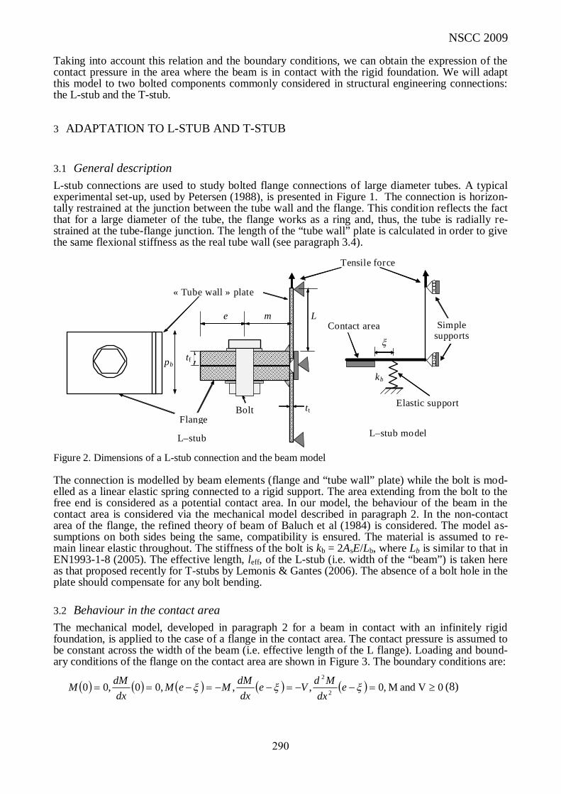
3.1 General description L-stub connections are used to study bolted flange connections of large diameter tubes. A typical experimental set-up, used by Petersen (1988), is presented in Figure 1. The connection is horizon-tally restrained at the junction between the tube wall and the flange. This condition reflects the fact that for a large diameter of the tube, the flange works as a ring and, thus, the tube is radially re-strained at the tube-flange junction. The length of the “tube wall” plate is calculated in order to give the same flexional stiffness as the real tube wall (see paragraph 3.4).
Figure 2. Dimensions of a L-stub connection and the beam model The connection is modelled by beam elements (flange and “tube wall” plate) while the bolt is mod-elled as a linear elastic spring connected to a rigid support. The area extending from the bolt to the free end is considered as a potential contact area. In our model, the behaviour of the beam in the contact area is considered via the mechanical model described in paragraph 2. In the non-contact area of the flange, the refined theory of beam of Baluch et al (1984) is considered. The model as-sumptions on both sides being the same, compatibility is ensured. The material is assumed to re-main linear elastic throughout. The stiffness of the bolt is kb = 2AsE/Lb, where Lb is similar to that in EN1993-1-8 (2005). The effective length, leff, of the L-stub (i.e. width of the “beam”) is taken here as that proposed recently for T-stubs by Lemonis & Gantes (2006). The absence of a bolt hole in the plate should compensate for any bolt bending.
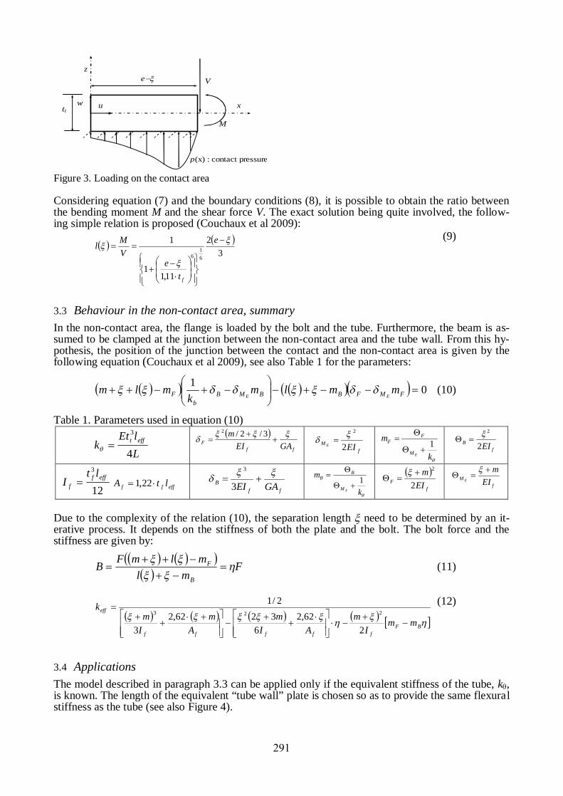
3.2 Behaviour in the contact area The mechanical model, developed in paragraph 2 for a beam in contact with an infinitely rigid foundation, is applied to the case of a flange in the contact area. The contact pressure is assumed to be constant across the width of the beam (i.e. effective length of the L flange). Loading and bound-ary conditions of the flange on the contact area are shown in Figure 3. The boundary conditions are:
0V and M ,0,,,00,00 2
2
edx
MdVedx
dMMeMdx
dMM (8)
Bolt
Tensile force
pb
« Tube wall » plate
Le m
tf
tt Flange
kb
Simple supports
Elastic support
Contact area
L–stub L–stub model
290
x w
p(x) : contact pressure
tf
e
M
V
z
u
Figure 3. Loading on the contact area
Considering equation (7) and the boundary conditions (8), it is possible to obtain the ratio between the bending moment M and the shear force V. The exact solution being quite involved, the follow-ing simple relation is proposed (Couchaux et al 2009):
3
2
11,11
1
61
6
e
te
VMl
f
(9)
3.3 Behaviour in the non-contact area, summary In the non-contact area, the flange is loaded by the bolt and the tube. Furthermore, the beam is as-sumed to be clamped at the junction between the non-contact area and the tube wall. From this hy-pothesis, the position of the junction between the contact and the non-contact area is given by the following equation (Couchaux et al 2009), see also Table 1 for the parameters:
01
FMFBBMB
bF mmlm
kmlm
EE (10)
Table 1. Parameters used in equation (10)
LlEt
k efft
4
3
ffF GAEI
m
3/2/2 f
M EIE 2
2
k
m
EM
FF 1
fB EI2
2
12
3efff
f
ltI effff ltA 22,1
ffB GAEI
3
3
k
m
EM
BB 1
f
F EIm
2
2
f
M EIm
E
Due to the complexity of the relation (10), the separation length need to be determined by an it-erative process. It depends on the stiffness of both the plate and the bolt. The bolt force and the stiffness are given by:
F
mlmlmFB
B
F
(11)
BF
fffff
eff
mmI
mAI
mA
mIm
k
262,2
63262,2
3
2/1223
(12)
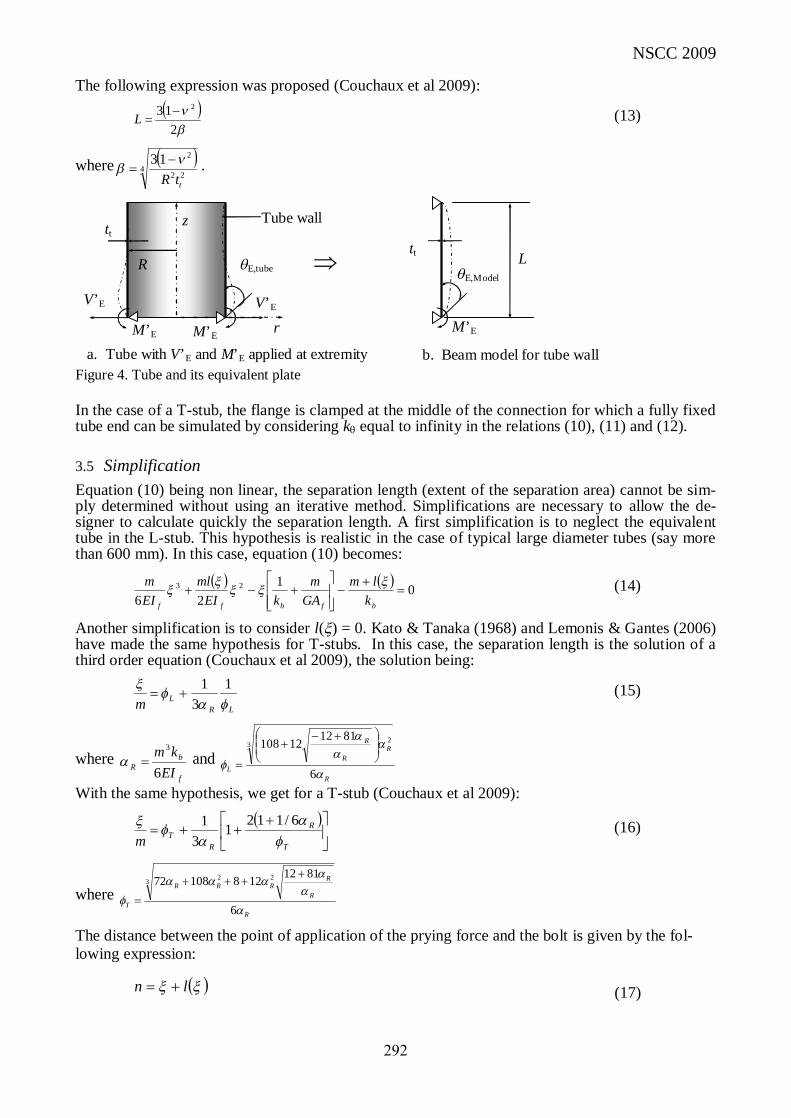
3.4 Applications The model described in paragraph 3.3 can be applied only if the equivalent stiffness of the tube, k, is known. The length of the equivalent “tube wall” plate is chosen so as to provide the same flexural stiffness as the tube (see also Figure 4).
291
NSCC 2009
The following expression was proposed (Couchaux et al 2009):
213 2
L (13)
where 4
22
213
ttR
.
tt
E,tube E,Model
b. Beam model for tube wall
M’E r
z
M’E
V’E
M’E
Tube wall
V’E
L R
a. Tube with V’E and M’E applied at extremity
tt
Figure 4. Tube and its equivalent plate
In the case of a T-stub, the flange is clamped at the middle of the connection for which a fully fixed tube end can be simulated by considering k equal to infinity in the relations (10), (11) and (12).
3.5 Simplification Equation (10) being non linear, the separation length (extent of the separation area) cannot be sim-ply determined without using an iterative method. Simplifications are necessary to allow the de-signer to calculate quickly the separation length. A first simplification is to neglect the equivalent tube in the L-stub. This hypothesis is realistic in the case of typical large diameter tubes (say more than 600 mm). In this case, equation (10) becomes:
0126
23
bfbff klm
GAm
kEIml
EIm
(14)
Another simplification is to consider l() = 0. Kato & Tanaka (1968) and Lemonis & Gantes (2006) have made the same hypothesis for T-stubs. In this case, the separation length is the solution of a third order equation (Couchaux et al 2009), the solution being:
LRLm
1
31
(15)
where f
bR EI
km6
3
and R
RR
R
L
6
81121210832
With the same hypothesis, we get for a T-stub (Couchaux et al 2009):
T
R
RTm
6/1121
31 (16)
where R
R
RRRR
T
6
8112128108723 22
The distance between the point of application of the prying force and the bolt is given by the fol-lowing expression:
ln (17)
292
In EN1993-1-8 (2005), for T -stubs, this distance is calculated with the following expression: m,;eminn 251 (18)
4 NUMERICAL MODEL AND COMPARISONS
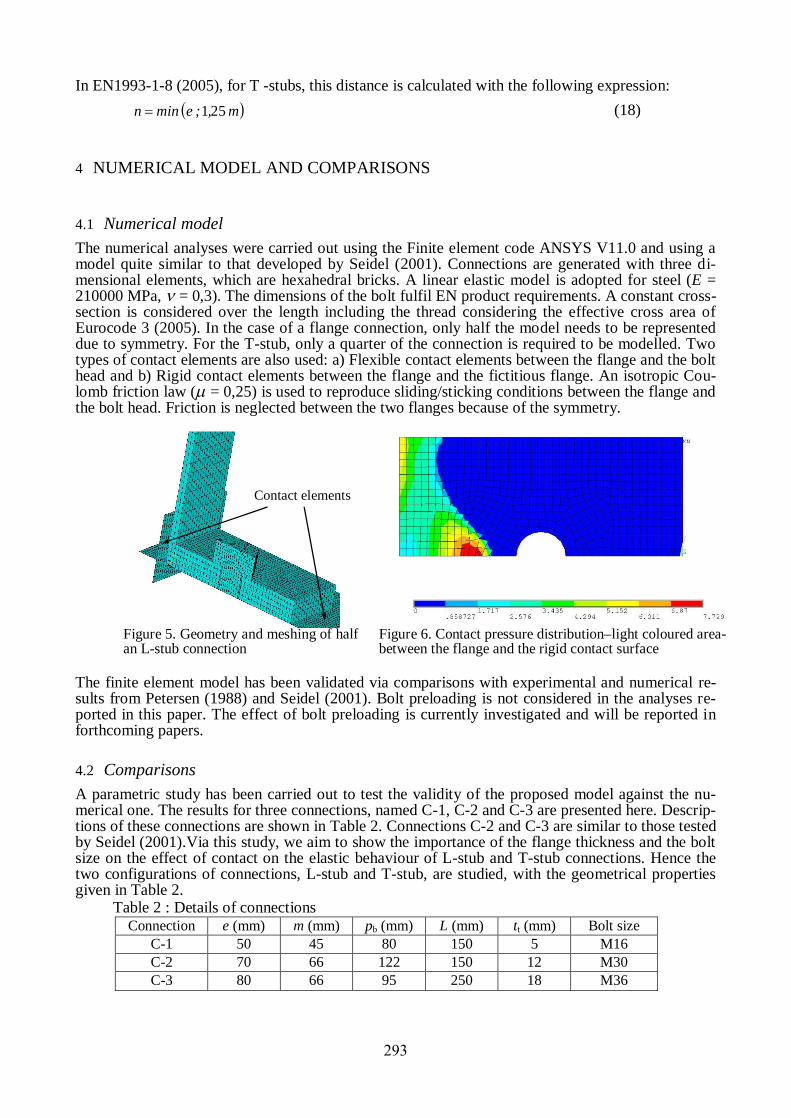
4.1 Numerical model The numerical analyses were carried out using the Finite element code ANSYS V11.0 and using a model quite similar to that developed by Seidel (2001). Connections are generated with three di-mensional elements, which are hexahedral bricks. A linear elastic model is adopted for steel (E = 210000 MPa, = 0,3). The dimensions of the bolt fulfil EN product requirements. A constant cross-section is considered over the length including the thread considering the effective cross area of Eurocode 3 (2005). In the case of a flange connection, only half the model needs to be represented due to symmetry. For the T-stub, only a quarter of the connection is required to be modelled. Two types of contact elements are also used: a) Flexible contact elements between the flange and the bolt head and b) Rigid contact elements between the flange and the fictitious flange. An isotropic Cou-lomb friction law (= 0,25) is used to reproduce sliding/sticking conditions between the flange and the bolt head. Friction is neglected between the two flanges because of the symmetry.
Contact elements
Figure 5. Geometry and meshing of half an L-stub connection
Figure 6. Contact pressure distribution–light coloured area-between the flange and the rigid contact surface
The finite element model has been validated via comparisons with experimental and numerical re-sults from Petersen (1988) and Seidel (2001). Bolt preloading is not considered in the analyses re-ported in this paper. The effect of bolt preloading is currently investigated and will be reported in forthcoming papers.
4.2 Comparisons A parametric study has been carried out to test the validity of the proposed model against the nu-merical one. The results for three connections, named C-1, C-2 and C-3 are presented here. Descrip-tions of these connections are shown in Table 2. Connections C-2 and C-3 are similar to those tested by Seidel (2001).Via this study, we aim to show the importance of the flange thickness and the bolt size on the effect of contact on the elastic behaviour of L-stub and T-stub connections. Hence the two configurations of connections, L-stub and T-stub, are studied, with the geometrical properties given in Table 2.
Table 2 : Details of connections Connection e (mm) m (mm) pb (mm) L (mm) tt (mm) Bolt size
C-1 50 45 80 150 5 M16 C-2 70 66 122 150 12 M30 C-3 80 66 95 250 18 M36
293
NSCC 2009
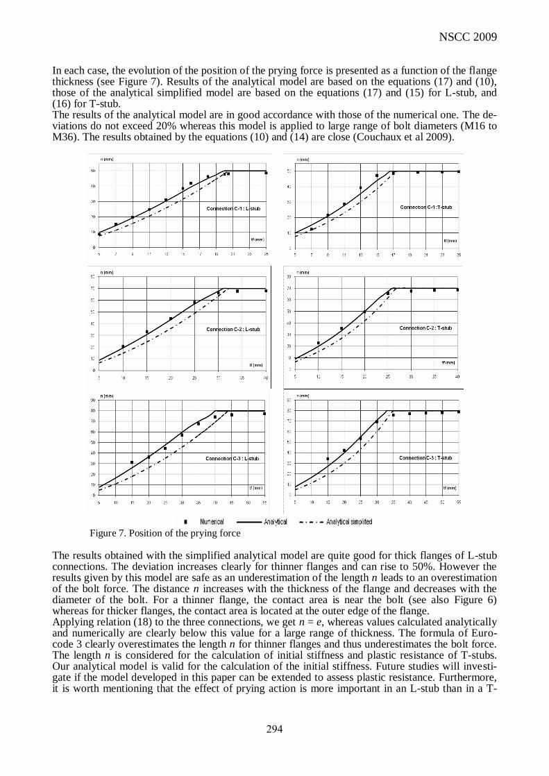
In each case, the evolution of the position of the prying force is presented as a function of the flange thickness (see Figure 7). Results of the analytical model are based on the equations (17) and (10), those of the analytical simplified model are based on the equations (17) and (15) for L-stub, and (16) for T-stub. The results of the analytical model are in good accordance with those of the numerical one. The de-viations do not exceed 20% whereas this model is applied to large range of bolt diameters (M16 to M36). The results obtained by the equations (10) and (14) are close (Couchaux et al 2009).
Figure 7. Position of the prying force The results obtained with the simplified analytical model are quite good for thick flanges of L-stub connections. The deviation increases clearly for thinner flanges and can rise to 50%. However the results given by this model are safe as an underestimation of the length n leads to an overestimation of the bolt force. The distance n increases with the thickness of the flange and decreases with the diameter of the bolt. For a thinner flange, the contact area is near the bolt (see also Figure 6) whereas for thicker flanges, the contact area is located at the outer edge of the flange. Applying relation (18) to the three connections, we get n = e, whereas values calculated analytically and numerically are clearly below this value for a large range of thickness. The formula of Euro-code 3 clearly overestimates the length n for thinner flanges and thus underestimates the bolt force. The length n is considered for the calculation of initial stiffness and plastic resistance of T-stubs. Our analytical model is valid for the calculation of the initial stiffness. Future studies will investi-gate if the model developed in this paper can be extended to assess plastic resistance. Furthermore, it is worth mentioning that the effect of prying action is more important in an L-stub than in a T-
294
stub (which is clamped at the middle). An application of the EC3 formula doesn’t seem to be safe in the case of L-stub connections.
5 CONCLUSION
In this paper, an analytical model for bolted connections has been proposed taking into account con-tact interactions. The connection behaviour is analysed using a mechanical model for beam in con-tact with an infinitely rigid support. This model is applied to two particular types of bolted connec-tion components; L-stub connections and T-stubs. A 3D finite element model has been developed in order to validate the analytical model. Contact elements are used between the flange and the bolt and rigid areas. Analytical and numerical results are in good agreement which demonstrate the validity of the proposed analytical model. The theo-retical and numerical results confirm that prying action increases when the ratio between the flange rigidity and the bolt rigidity becomes high. In the case of thicker flanges, the prying force is concen-trated at the flange edges. For T-stubs, this study shows that the predictions of Eurocode 3 are not always in good agreement with either theoretical or numerical results. While in this paper the influ-ence of bolt preloading has been neglected, it has a significant influence on the elastic behaviour of bolted connections. Bolt preloading can be taken into consideration in our model and further work is under way to investigate it.
REFERENCES
Seidel, M. (2001), Zur Bemessung geschraubter Ringflanschverbindungen von Windenergieanlangen, Insti-tut fur Stahlbau, Dissertation, Heft 20, Universität Hannover. EN 1993-1-8: Eurocode 3 (May 2005): Design of steel structures – Part 1–8: Designs of joints. Petersen, Ch. (1988): Stahlbau (Steel Construction), Braunschweig: Vieweg-Verlag. Agatonovic, P. (1985), Beam model of bolted flanged connection, Engineering Computation, Vol2, p21-29. Kato, B., Tanaka, A. (1968), Experimental study on tension-type high strength bolted connection (No.2 Pry-ing Action), Transaction of the architectural institute of Japan, Vol72, No147, p33-41 (in Japanese). Lemonis, M.E., Gantes, C.J. (2006), Incremental modelling of T-stub connections, Journal of Mechanics of materials and structures, Vol 1, Issue 7, 1135-1157. Senda, H., Suzuki, T., Ogawa, T. (1996), Inelastic behaviour of bolted T-stub connections, Journal of struc-tural and construction engineering, Transaction of AIJ, No476, p159-168 (in Japanese). Bakhiet, E. (1994), Etude des assemblages boulonnés à chargement fortement excentré soumis à des sollici-tations de fatigue, Thèse N°319, INSA de Toulouse (in french). Chakhari, J. (2007), Modélisation d’une fixation par éléments filetés d’une structure à forte excentration de chargement et soumise à des sollicitations en fatigue, Thèse de doctorat de l’INSAT et de l’ENIT (in french). Baluch, M.H., Azad, A.K., Khidir, M.A. (1984), Technical Theory of Beams with normal strain, Journal of Engineering Mechanics, Vol110, Issue 8, p1233-1237. Couchaux, M., Hjiaj, M., Ryan, I., Bureau, A. (2009), Analyse de l’effet de levier dans les assemblages bou-lonnés, Partie I : Etude théorique, Revue Construction métallique, N°2 (in french).
295