effect of damage on strength and durability
TRANSCRIPT

Effect of Damage on Strength and Durability
Mohan M. Ratwani, Ph. D R-Tec
28441 Highridge Road, Suite 530 Rolling Hills Estates, CA 90274-4886
USA
1.0 INTRODUCTION
All structures are prone to damage during their lifetime. The damage may be introduced in the structure when it is manufactured or may be caused by in-service environment or initiate during the service life of a structure. Various damage types occurring in metallic and composite structures are shown in Table 1. The sources of damage in metallic structures and their effect on structural integrity of metallic structures are well established and are not discussed in the present paper.
Table 1: Common Damage/Defects in Metallic and Composite Structures
Aircraft structures are designed to meet durability and damage tolerance requirements to ensure that the structure is safely operated during its design life without catastrophic failure. The prime examples of defects/damage in composite structures with their source are summarized in Table 2 (Ref. 1). It may be noted that battle damage, engine disintegration, and lightning are not a part of damage tolerance design.
Metallic Structures Composite Structures Flawed Fastener Holes Flawed Fastener Holes Fatigue Cracks Delaminations Corrosion Porosity Stress Corrosion Matrix Cracking Foreign Object Damage Foreign Object Damage
RTO-EN-AVT-156 5 - 1

Report Documentation Page Form ApprovedOMB No. 0704-0188
Public reporting burden for the collection of information is estimated to average 1 hour per response, including the time for reviewing instructions, searching existing data sources, gathering andmaintaining the data needed, and completing and reviewing the collection of information. Send comments regarding this burden estimate or any other aspect of this collection of information,including suggestions for reducing this burden, to Washington Headquarters Services, Directorate for Information Operations and Reports, 1215 Jefferson Davis Highway, Suite 1204, ArlingtonVA 22202-4302. Respondents should be aware that notwithstanding any other provision of law, no person shall be subject to a penalty for failing to comply with a collection of information if itdoes not display a currently valid OMB control number.
1. REPORT DATE MAY 2010
2. REPORT TYPE N/A
3. DATES COVERED -
4. TITLE AND SUBTITLE Effect of Damage on Strength and Durability
5a. CONTRACT NUMBER
5b. GRANT NUMBER
5c. PROGRAM ELEMENT NUMBER
6. AUTHOR(S) 5d. PROJECT NUMBER
5e. TASK NUMBER
5f. WORK UNIT NUMBER
7. PERFORMING ORGANIZATION NAME(S) AND ADDRESS(ES) R-Tec 28441 Highridge Road, Suite 530 Rolling Hills Estates, CA90274-4886, USA
8. PERFORMING ORGANIZATIONREPORT NUMBER
9. SPONSORING/MONITORING AGENCY NAME(S) AND ADDRESS(ES) 10. SPONSOR/MONITOR’S ACRONYM(S)
11. SPONSOR/MONITOR’S REPORT NUMBER(S)
12. DISTRIBUTION/AVAILABILITY STATEMENT Approved for public release, distribution unlimited
13. SUPPLEMENTARY NOTES See also ADA564486. Battle Damage Repair Techniques and Procedures on Air Vehicles - Lessons Learnedand Prospects. RTO-EN-AVT-156
14. ABSTRACT
15. SUBJECT TERMS
16. SECURITY CLASSIFICATION OF: 17. LIMITATION OF ABSTRACT
SAR
18. NUMBEROF PAGES
22
19a. NAME OFRESPONSIBLE PERSON
a. REPORT unclassified
b. ABSTRACT unclassified
c. THIS PAGE unclassified
Standard Form 298 (Rev. 8-98) Prescribed by ANSI Std Z39-18

Table 2: Common Defects/Damage in Composites and Source
Various types of damages, including battle damage, in composites and their effects on strength and durability are discussed here. The extent of damage covered by damage tolerant design is also discussed.
2.0 EFFECTS OF DAMAGE/DEFECTS IN COMPOSITES
2.1 Porosity Porosity is one of the most common defects found in composite parts. The porosity is caused by inadequate tooling, incorrect lay-up and cure procedure. The presence of porosity can degrade structural strength depending on the extent and location of the porosity in the composite component. A typical photomicrograph of a composite laminate showing porosity is shown in Figure 1.
Figure 1: Photomicrograph of Composite Showing Porosity.
Ultrasonic C-scan or X-ray radiography during quality control generally detects the porosity. These techniques show only the presence of porosity but not the quantitative level. In order to determine the influence of porosity on structural performance it is necessary to know the quantitative level of porosity.
DEFECT/DAMAGE SOURCE TYPE Manufacturing Defects Porosity Lay-up/Processing Flawed Fastener Holes Fabrication/Assembly Delaminations Processing, Fabrication, Assembly During Service Flawed Holes, Gouges, Servicing access damage, Scratches Access attachments Impact Damage Service carts, Work stands, Tool boxes, Tools Flight/Taxi Impact, Penetration Hail, Bird, Detached fairing, Runway Debris, Blown tires Service Delaminations Flight loads- (Initiation at Holes, Ply-drop-offs) Repair Similar to manufacturing defects Other Damages Battle damage, Engine disintegration, Lightning
Effect of Damage on Strength and Durability
5 - 2 RTO-EN-AVT-156
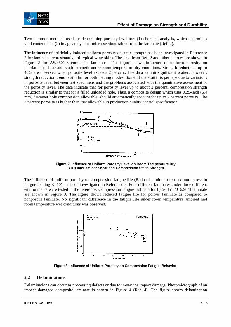
Two common methods used for determining porosity level are: (1) chemical analysis, which determines void content, and (2) image analysis of micro-sections taken from the laminate (Ref. 2).
The influence of artificially induced uniform porosity on static strength has been investigated in Reference 2 for laminates representative of typical wing skins. The data from Ref. 2 and other sources are shown in Figure 2 for AS/3501-6 composite laminates. The figure shows influence of uniform porosity on interlaminar shear and static strength under room temperature dry conditions. Strength reductions up to 40% are observed when porosity level exceeds 2 percent. The data exhibit significant scatter, however, strength reduction trend is similar for both loading modes. Some of the scatter is perhaps due to variations in porosity level between test specimens and the problems associated with the quantitative assessment of the porosity level. The data indicate that for porosity level up to about 2 percent, compression strength reduction is similar to that for a filled unloaded hole. Thus, a composite design which uses 0.25-inch (6.4 mm) diameter hole compression allowable, should automatically account for up to 2 percent porosity. The 2 percent porosity is higher than that allowable in production quality control specification.
Figure 2: Influence of Uniform Porosity Level on Room Temperature Dry (RTD) Interlaminar Shear and Compression Static Strength.
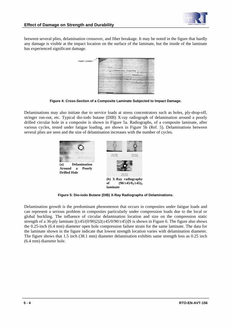
The influence of uniform porosity on compression fatigue life (Ratio of minimum to maximum stress in fatigue loading R=10) has been investigated in Reference 3. Four different laminates under three different environments were tested in the reference. Compression fatigue test data for [(45/-45)5/016/904] laminate are shown in Figure 3. The figure shows reduced fatigue life for porous laminate as compared to nonporous laminate. No significant difference in the fatigue life under room temperature ambient and room temperature wet conditions was observed.
Figure 3: Influence of Uniform Porosity on Compression Fatigue Behavior.
2.2 Delaminations Delaminations can occur as processing defects or due to in-service impact damage. Photomicrograph of an impact damaged composite laminate is shown in Figure 4 (Ref. 4). The figure shows delamination
Effect of Damage on Strength and Durability
RTO-EN-AVT-156 5 - 3
between several plies, delamination crossover, and fiber breakage. It may be noted in the figure that hardly any damage is visible at the impact location on the surface of the laminate, but the inside of the laminate has experienced significant damage.
Figure 4: Cross-Section of a Composite Laminate Subjected to Impact Damage.
Delaminations may also initiate due to service loads at stress concentrators such as holes, ply-drop-off, stringer run-out, etc. Typical dio-iodo butane (DIB) X-ray radiograph of delamination around a poorly drilled circular hole in a composite is shown in Figure 5a. Radiographs, of a composite laminate, after various cycles, tested under fatigue loading, are shown in Figure 5b (Ref. 5). Delaminations between several plies are seen and the size of delamination increases with the number of cycles.
Figure 5: Dio-iodo Butane (DIB) X-Ray Radiographs of Delaminations.
Delamination growth is the predominant phenomenon that occurs in composites under fatigue loads and can represent a serious problem in composites particularly under compression loads due to the local or global buckling. The influence of circular delamination location and size on the compression static strength of a 36-ply laminate [(±45/(0/90)2)2(±45/0/90/±45)]S is shown in Figure 6. The figure also shows the 0.25-inch (6.4 mm) diameter open hole compression failure strain for the same laminate. The data for the laminate shown in the figure indicate that lowest strength location varies with delamination diameter. The figure shows that 1.5 inch (38.1 mm) diameter delamination exhibits same strength loss as 0.25 inch (6.4 mm) diameter hole.
(a) Delamination Around a Poorly Drilled Hole
(b) X-Ray radiography of (90/±45/03/±45)S laminate
Effect of Damage on Strength and Durability
5 - 4 RTO-EN-AVT-156

Figure 6: Influence of Delamination Location and Size on Compression Static Strength.
The influence of delamination location on compression fatigue life (R=10) is shown in Figure 7 (Ref. 6). In the figure, cyclic minimum stress, normalized with respect to damaged static failure stress, is plotted as a function of cycles. The data indicate that delamination location influences the fatigue threshold. The fatigue threshold increases as delamination depth increases.
Figure 7: Influence of Delamination Location on Compression Fatigue Behavior (R=10).
2.3 Surface Flaws Surface flaws generally occur in composite structures during assembly of built-up structures. The surface flaws cause local stress concentration which will degrade the strength of a structure.
The influence of half through-the-thickness holes and cracks is investigated in Ref. 7-9. Figure 8 shows the effect of half and through penetration slits and holes on static tension strength of T300/5208 composite material. For a given slit or hole size, the reduction in tension strength due to half penetration defects is not as severe as that for full penetration. At large defect sizes the strength reduction plots become asymptotic (at 6000μ inch/inch strain for half penetration and 3,600μ inch/inch for full penetration).
Effect of Damage on Strength and Durability
RTO-EN-AVT-156 5 - 5
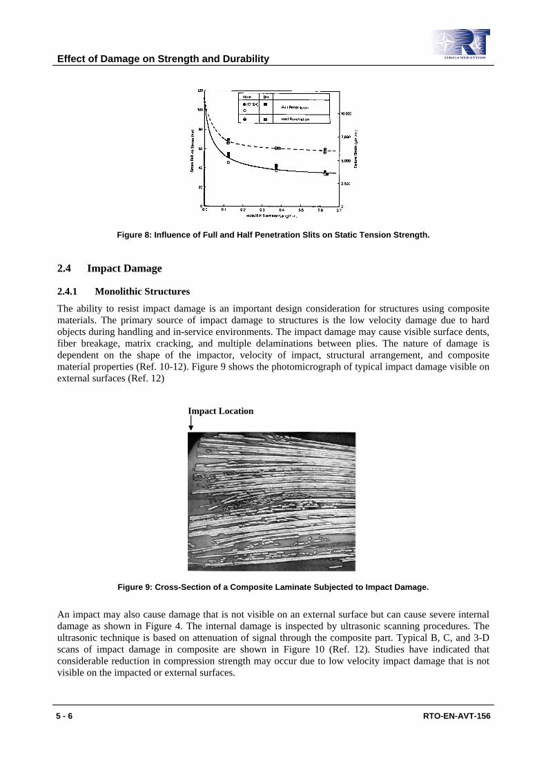
Figure 8: Influence of Full and Half Penetration Slits on Static Tension Strength.
2.4 Impact Damage
2.4.1 Monolithic Structures
The ability to resist impact damage is an important design consideration for structures using composite materials. The primary source of impact damage to structures is the low velocity damage due to hard objects during handling and in-service environments. The impact damage may cause visible surface dents, fiber breakage, matrix cracking, and multiple delaminations between plies. The nature of damage is dependent on the shape of the impactor, velocity of impact, structural arrangement, and composite material properties (Ref. 10-12). Figure 9 shows the photomicrograph of typical impact damage visible on external surfaces (Ref. 12)
Impact Location
Figure 9: Cross-Section of a Composite Laminate Subjected to Impact Damage.
An impact may also cause damage that is not visible on an external surface but can cause severe internal damage as shown in Figure 4. The internal damage is inspected by ultrasonic scanning procedures. The ultrasonic technique is based on attenuation of signal through the composite part. Typical B, C, and 3-D scans of impact damage in composite are shown in Figure 10 (Ref. 12). Studies have indicated that considerable reduction in compression strength may occur due to low velocity impact damage that is not visible on the impacted or external surfaces.
Effect of Damage on Strength and Durability
5 - 6 RTO-EN-AVT-156

Figure 10: B, C and 3-D Scans of Typical Impact Damage in Composite Laminate.
A typical variation of strength degradation as a function of impact energy is shown in Figure 11 for both tensile as well as compression loading. The figure shows that compression loading causes much more reduction in strength as compared to tensile loading. At low energy levels, the reduction in tensile strength is not significant but reduction in compression strength is large. This is due to the fact that impact damage at low energy levels causes primarily delaminations, which cause strength degradation due to buckling under compression loading. At higher impact energy levels, impact damage causes fiber breakage, which results in significant tensile strength reduction (Ref. 6).
Figure 11: Tensile and Compression Strength Degradation Due to Impact Damage.
The damage due to impact may grow under subsequent fatigue loads depending on the load levels, load amplitude, size of the damage, and the location of the damage in the structure. A typical growth record, obtained by ultrasonic C-Scan, for a composite laminate, tested under fatigue loading at R= -1 and –650F (-550C), is shown in Figure 12. The figure shows that the damage grows primarily in the direction at right angles to the applied loading.
Effect of Damage on Strength and Durability
RTO-EN-AVT-156 5 - 7

Figure 12: C-Scan of Impact Damage Growth in Specimen Tested Under Fatigue Loading.
2.4.2 Sandwich Structures
Susceptibility to impact damage is a point of major concern in the design of sandwich structures with composite face sheets. Low velocity impact damage may be caused by tool drop, hail or runway debris. Low velocity impact generally affects outer face sheets and inner face sheets remain intact and maintain continuous load path. Energy dissipation in composite sandwich panels takes place through matrix cracking, fiber breakage, delaminations and core failures. The energy dissipation is dependent on many parameters such as face sheet materials and thickness, core material and density, core cell size, and core wall thickness. Typical impact damage in a sandwich panel with composite face sheets and honeycomb core is shown in Figure 13.
Figure 13: Impact Damage in Sandwich Panel with Honeycomb Core.
Core damage characteristics in honeycomb and foam cores are schematically shown in Figure 14 and 15, respectively, for energy levels of 4 ft-lb (5.4 J) and 6 ft-lb (8.1 J). The extent of core damage is dependant on the impact energy level. Completely crushed core occurs at impact site with buckled and cracked core in the surrounding area. For foam core damage area is localized. Foam damage area is almost the same size as the face sheet damage.
Effect of Damage on Strength and Durability
5 - 8 RTO-EN-AVT-156
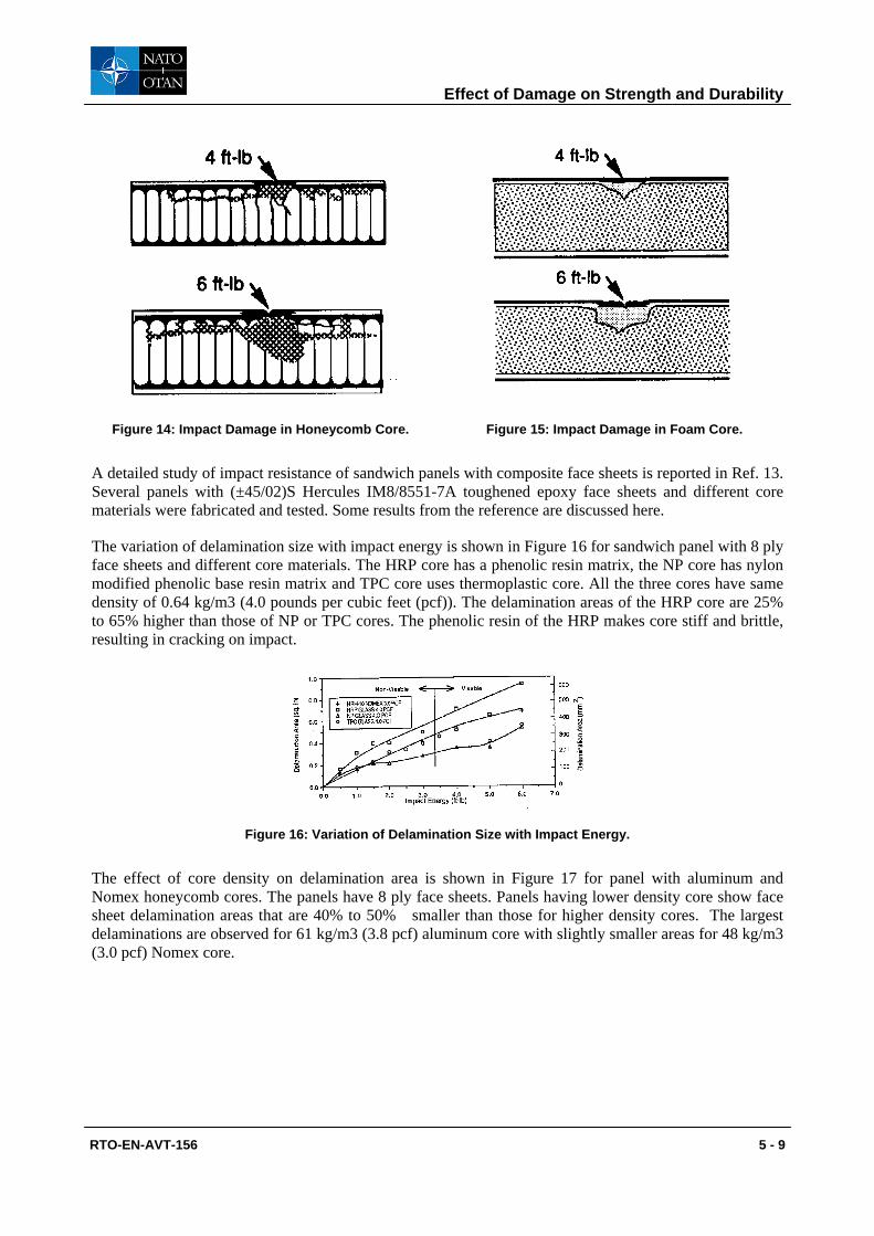
Figure 14: Impact Damage in Honeycomb Core. Figure 15: Impact Damage in Foam Core.
A detailed study of impact resistance of sandwich panels with composite face sheets is reported in Ref. 13. Several panels with (±45/02)S Hercules IM8/8551-7A toughened epoxy face sheets and different core materials were fabricated and tested. Some results from the reference are discussed here.
The variation of delamination size with impact energy is shown in Figure 16 for sandwich panel with 8 ply face sheets and different core materials. The HRP core has a phenolic resin matrix, the NP core has nylon modified phenolic base resin matrix and TPC core uses thermoplastic core. All the three cores have same density of 0.64 kg/m3 (4.0 pounds per cubic feet (pcf)). The delamination areas of the HRP core are 25% to 65% higher than those of NP or TPC cores. The phenolic resin of the HRP makes core stiff and brittle, resulting in cracking on impact.
Figure 16: Variation of Delamination Size with Impact Energy.
The effect of core density on delamination area is shown in Figure 17 for panel with aluminum and Nomex honeycomb cores. The panels have 8 ply face sheets. Panels having lower density core show face sheet delamination areas that are 40% to 50% smaller than those for higher density cores. The largest delaminations are observed for 61 kg/m3 (3.8 pcf) aluminum core with slightly smaller areas for 48 kg/m3 (3.0 pcf) Nomex core.
Effect of Damage on Strength and Durability
RTO-EN-AVT-156 5 - 9
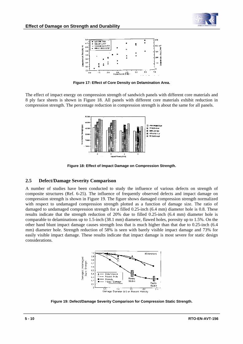
Figure 17: Effect of Core Density on Delamination Area.
The effect of impact energy on compression strength of sandwich panels with different core materials and 8 ply face sheets is shown in Figure 18. All panels with different core materials exhibit reduction in compression strength. The percentage reduction in compression strength is about the same for all panels.
Figure 18: Effect of Impact Damage on Compression Strength.
2.5 Defect/Damage Severity Comparison A number of studies have been conducted to study the influence of various defects on strength of composite structures (Ref. 6-25). The influence of frequently observed defects and impact damage on compression strength is shown in Figure 19. The figure shows damaged compression strength normalized with respect to undamaged compression strength plotted as a function of damage size. The ratio of damaged to undamaged compression strength for a filled 0.25-inch (6.4 mm) diameter hole is 0.8. These results indicate that the strength reduction of 20% due to filled 0.25-inch (6.4 mm) diameter hole is comparable to delaminations up to 1.5-inch (38.1 mm) diameter, flawed holes, porosity up to 1.5%. On the other hand blunt impact damage causes strength loss that is much higher than that due to 0.25-inch (6.4 mm) diameter hole. Strength reduction of 58% is seen with barely visible impact damage and 73% for easily visible impact damage. These results indicate that impact damage is most severe for static design considerations.
Figure 19: Defect/Damage Severity Comparison for Compression Static Strength.
Effect of Damage on Strength and Durability
5 - 10 RTO-EN-AVT-156
3.0 DAMAGE TOLERANCE REQUIREMENTS
Different certification agencies have different damage tolerance requirements depending on the type of aircraft. The initial flaw assumptions for metallic and composite structures are significantly different. Table 3 shows the initial flaw assumptions for United States Air Force composite aircraft design (Ref. 15).
Table 3: Initial Flaw/Damage Assumptions
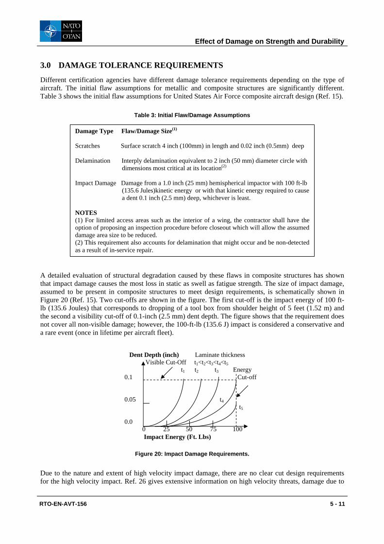
A detailed evaluation of structural degradation caused by these flaws in composite structures has shown that impact damage causes the most loss in static as swell as fatigue strength. The size of impact damage, assumed to be present in composite structures to meet design requirements, is schematically shown in Figure 20 (Ref. 15). Two cut-offs are shown in the figure. The first cut-off is the impact energy of 100 ft-lb (135.6 Joules) that corresponds to dropping of a tool box from shoulder height of 5 feet (1.52 m) and the second a visibility cut-off of 0.1-inch (2.5 mm) dent depth. The figure shows that the requirement does not cover all non-visible damage; however, the 100-ft-lb (135.6 J) impact is considered a conservative and a rare event (once in lifetime per aircraft fleet).
Figure 20: Impact Damage Requirements.
Due to the nature and extent of high velocity impact damage, there are no clear cut design requirements for the high velocity impact. Ref. 26 gives extensive information on high velocity threats, damage due to
Dent Depth (inch) Laminate thickness Visible Cut-Off t1<t2<t3<t4<t5 t1 t2 t3 Energy 0.1 Cut-off 0.05 t4 t5 0.0 0 25 50 75 100 Impact Energy (Ft. Lbs)
Damage Type Flaw/Damage Size(1) Scratches Surface scratch 4 inch (100mm) in length and 0.02 inch (0.5mm) deep Delamination Interply delamination equivalent to 2 inch (50 mm) diameter circle with dimensions most critical at its location(2)
Impact Damage Damage from a 1.0 inch (25 mm) hemispherical impactor with 100 ft-lb (135.6 Jules)kinetic energy or with that kinetic energy required to cause a dent 0.1 inch (2.5 mm) deep, whichever is least. NOTES (1) For limited access areas such as the interior of a wing, the contractor shall have the option of proposing an inspection procedure before closeout which will allow the assumed damage area size to be reduced. (2) This requirement also accounts for delamination that might occur and be non-detected as a result of in-service repair.
Effect of Damage on Strength and Durability
RTO-EN-AVT-156 5 - 11

the threats, and their effect on the structural integrity of aircraft structures. The reference gives the following guidelines for impact damage tolerance:
• The aircraft should be capable of sustaining a single impact by the design threat without failing strength critical structure when loaded at the time of impact with two-third of limit load.
• The damaged aircraft should be capable of sustaining limit load without failing strength critical structure during the remaining mission profile.
• The alteration or extension of the projectile damage, caused by the cyclic loading environment, should be determined for the mission segment between projectile impact and return to the base or sortie completion; and the effect of alteration or extension should be considered on strength, stiffness and rigidity requirements.
• After being damaged by the design threat, the aircraft should be free from flutter, divergence, and other aeroelastic instabilities at all speeds up to limit speed for the remainder of mission profile for each threat, mission and encounter condition specified.
4.0 HIGH VELOCITY IMPACT DAMAGE
The survivability of an aircraft in a non-nuclear environment is of considerable concern to designers. Aircraft structures are subjected to rapid loss of strength and possible catastrophic failure following high velocity impact from ballistic threats. Several investigators have attempted to characterize damage due to ballistic threats and analytical and empirical models have been developed. Some aspects of high velocity impact damage are briefly discussed here.
4.1 Ballistic Threats Non-nuclear threats are categorized (References 26-27) in four types- 1) Non-exploding projectiles, 2) High Explosive (HE) exploding projectiles, 3) Missile Warheads, and 4) High energy lasers. There are several types of non-exploding projectiles including ball (B), armor piercing (AP), incendiary (I) and tracer (T). Ball projectiles, available in 7.62 mm, have a soft core deigned to deform at impact, and are intended for use against personnel. Armor piercing projectiles (typically available in 7.62, 12.7 and 14.5 mm) have a hardened steel core designed to pierce hard targets. An incendiary projectile contains thermally active filler that works on an impact and is capable of igniting onboard flammable fluids such as fuel and hydraulic fluid. Trace projectile contains material that burns brightly along the flight path and provides assistance in aiming and sighting. High explosive (HE) projectiles contain an explosive charge that is activated by impact. HE projectiles are of two types-“superquick” and “delayed”. The “superquick” detonates on impact with the surface while the “delayed” fuse projectiles are designed to detonate after penetration in a structure. Most common projectiles are 23, 30, 36 and 57 mm.
Missile fragments from surface-to-air (SAM) and air-to-air (AAM) missiles can cause severe damage to aircraft structures. Missile fragmentation warheads (Ref. 26) consist of an explosive charge surrounded by a wall of perforated metal fragments. Warheads generally have a proximity fuse. At detonation the fragments spread outwards at a very high velocity. The shape and weight of fragments depends on the type of warheads.
4.2 Blast Response Prediction Codes Significant work (e.g. Ref. 26-32) has been done to develop analytical techniques and computer codes to predict response of structures to impact from threats such as small arms projectiles, high explosive projectiles, and missile warhead fragments. These techniques and codes predict structural response, penetration capability, damage size and type, strength and stiffness degradation, load redistribution and failure. Some of the codes are briefly discussed here.
Effect of Damage on Strength and Durability
5 - 12 RTO-EN-AVT-156

In Ref. 29-30, a finite element code BR-1 “Blast Response” has been developed to predict transient structural response of metallic structures to internal blast. The code is capable of predicting- 1) the transient deflections, strains, and stresses of isotropic skin-rib-stringer type of aircraft panels, (2) the ultimate strain failures in the highly stressed locations in the panels, and (3) the skin areas that are removed by fragment penetration. In Ref. 31, BR-2 computer code was developed to predict amount of material removed from metallic panels due to fragment penetration. Analytical techniques to predict failure of panels, subjected to ballistic damage, are discussed in the reference. The BR-1 code has been extended to include composite materials and computer code BR-1FC has been developed in Ref. 32.
The pressures acting on an integral fuel tank structure as a result of projectile penetrating a tank and traversing the fuel (projectile exploding in a tank in the case of detonating projectiles) are referred to as hydrodynamic ram pressures. The structural response to these hydrodynamic pressures can be great enough to cause large structural damage to fuel tanks and in extreme case can result in a loss of an aircraft. The Hydraulic Ram Structural Response Computer Program (HRSR) has been developed in References 33-34. The methodology developed in these references has helped in developing design concepts for more survivable fuel tanks.
4.3 Extent of Damage The damage due to ballistic threat depends on factors such as- threat type, projectile velocity at the time of impact, angle of impact, panel material and thickness, substructure (such as ribs, spars, etc.). Characterizing the shape and extent of damage is rather difficult. Some damage examples are discussed here.
A portion of multi-spar 7075-T6 aluminum wing box was tested in Ref. 35. A three compartment wing box (Figure 21) was subjected to explosion of 23-mm HEI projectile in the central compartment. The damage to 0.25-inch (6.35 mm) thick entry wall was tapered hole with 1 inch (25.4 mm) diameter on entrance side and 1.5 inch (37.5 mm) on exit side as shown in Figure 22. The exit wall was severely damaged with about 50 square inches area removed (Figure 23). The spar damage is shown in Figure 24.
Effect of Damage on Strength and Durability
RTO-EN-AVT-156 5 - 13

(b) Test Panel Set-Up
Figure 21: Wing Box Test Panel.
Figure 22: Entry Wall Damage. Figure 23: Exit Wall Damage.
(a) Cross-Section of Test Panel
Effect of Damage on Strength and Durability
5 - 14 RTO-EN-AVT-156

Figure 24: Spar Damage.
The damage caused to integral fuel tanks is very severe due to hydrodynamic ram effects. The damage to entrance walls is generally not as severe as damage to exit walls for HEI projectiles. Typical damage to a composite fuel tank exit wall due to hydrodynamic ram effects is shown in Figure 25 (Ref. 36). The damage to the wet side of the exit wall shows significant delaminations with some fiber breakage. The damage to dry side of the exit wall has severe fiber breakage and delaminations.
Wet Side of Exit Panel
Dry Side of Exit Panel
Figure 25: Hydrodynamic Ram Damage to Composite Integral Fuel Tank.
4.4 Residual Strength of Impact Damaged Panels Empirical models, based on test data, have been developed to predict damage size caused by AP projectiles (Ref. 26, 35, 37-38). Using the predicted damage size and fracture mechanics approach, the residual strength of panels is predicted. A model, incorporating statistical variation in test data, has been developed in Ref. 39.
Effect of Damage on Strength and Durability
RTO-EN-AVT-156 5 - 15

Damage to composite and metallic structures due to fragments from HEI Projectiles can be predicted using computer codes discussed in Ref. 29-31. Models to predict residual strength of panels subjected to multiple fragment damage are discussed in Ref. 31, 38.
A model to predict stiffness degradation of panels subject to damage from AP projectiles is discussed in Ref. 26. This model is applicable to a panel with a single hole caused by a penetrating projectile. Ref. 39 discusses the model for stiffness degradation of panels subjected to multiple fragment damage from a HEI projectile.
5.0 FRACTURE CONTROL IN COMPOSITES
The fail-safe philosophy used in metallic structures requires that the structure sustain design limit load after the loss of a structural member due to a fatigue failure. This is generally achieved by reducing the stress intensity factor, K, at the tip of a fatigue crack by transferring the load to a connected member such as a stiffener. This results in a part of the load being transferred from skin to stiffener. The reduction in the skin loads reduces the stress intensity factors ahead of the crack tips in the skin. In contrast to metals, extensive test data have shown that composite materials do not show propensity to nucleation and growth of through the thickness cracks under cyclic loading. However, composite structures are susceptible to damage from ground handling and ballistic impacts. The ground handling impact causes matrix cracking, ply delaminations and possible fiber fractures. The ballistic impacts typically cause extensive fiber fractures and through cracks induced by projectile fragments. In the presence of such damage, composites under tension or compression loads exhibit sudden and catastrophic failures.
The test data reported in the literature have shown that using improved tougher resin systems (Ref. 40) can minimize matrix cracking and ply delaminations. Relatively low brittle fiber fracture characteristics of graphite laminates can be improved by inserting glass or Kevlar fibers to form a hybrid laminate system. However, since glass and Kevlar fibers have lower stiffness and strength efficiencies, it is desirable to use these only on a selective and limited basis, in order to optimize the hybrid laminate weight while achieving the desired stiffness, strength and damage tolerance properties.
5.1 Crack Arrestment Strip Concepts The use of crack arrestment strips also known as buffer strips or tear straps has shown to provide crack arrestment capability to composites (Ref. 41-47). A number of crack arrestment strip concepts have been investigated in literature. These are:
• Softening Strip Concept 1- Replace selected strips of 00 and 900 plies of the primary laminate with +45/-45 plies of the same material at selected locations as schematically shown in Figure 26.
• Softening Strip Concept 2- Replace selected strips of 00 plies of the primary laminate with 00 plies of lower modulus material at selected locations as shown in Figure 26.
Effect of Damage on Strength and Durability
5 - 16 RTO-EN-AVT-156

Figure 26: Softening Strip Concept.
• Co-cured Tear Strap Concept 3- Local build-up of the laminate at selected locations by adding plies of same material as shown in Figure 27 or adding plies of S-glass as shown in monolithic laminate of Figure 28. In Figure 28, each zero degree ply of the parent laminate in the crack arrestment strip zone has been replaced with two zero degree plies of S-glass or Kevlar. The introduction of zero degree plies of S-glass or Kevlar will significantly increase fracture toughness in the crack arrestment strip zone.
Figure 27: Interleaved Straps for Composite Construction.
Figure 28: Composite Panel with Buffer Strips having S-Glass or Kevlar Plies.
• Bonded Stiffener Reinforcement Concept 4- In this concept, stiffeners are bonded at selected locations as shown in Figure 29. The bonded stiffeners may be metallic or composite. This concept has been used in metallic structures where the stiffeners are either bonded or mechanically fastened.
A W W Buffer Buffer Strip D Strips D W W A Section A-A Buffer Strips (Softening Strips)- 00 Plies Replaced by +450/ -450 of Same Material or Replaced by 00 Plies of Material having Modulus Lower than Laminate (e.g. S-Glass)
Effect of Damage on Strength and Durability
RTO-EN-AVT-156 5 - 17
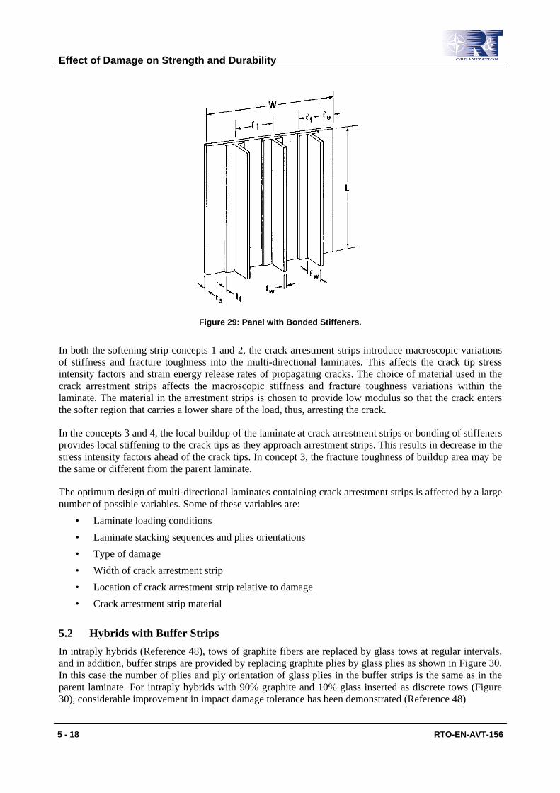
Figure 29: Panel with Bonded Stiffeners.
In both the softening strip concepts 1 and 2, the crack arrestment strips introduce macroscopic variations of stiffness and fracture toughness into the multi-directional laminates. This affects the crack tip stress intensity factors and strain energy release rates of propagating cracks. The choice of material used in the crack arrestment strips affects the macroscopic stiffness and fracture toughness variations within the laminate. The material in the arrestment strips is chosen to provide low modulus so that the crack enters the softer region that carries a lower share of the load, thus, arresting the crack.
In the concepts 3 and 4, the local buildup of the laminate at crack arrestment strips or bonding of stiffeners provides local stiffening to the crack tips as they approach arrestment strips. This results in decrease in the stress intensity factors ahead of the crack tips. In concept 3, the fracture toughness of buildup area may be the same or different from the parent laminate.
The optimum design of multi-directional laminates containing crack arrestment strips is affected by a large number of possible variables. Some of these variables are:
• Laminate loading conditions • Laminate stacking sequences and plies orientations • Type of damage • Width of crack arrestment strip • Location of crack arrestment strip relative to damage • Crack arrestment strip material
5.2 Hybrids with Buffer Strips In intraply hybrids (Reference 48), tows of graphite fibers are replaced by glass tows at regular intervals, and in addition, buffer strips are provided by replacing graphite plies by glass plies as shown in Figure 30. In this case the number of plies and ply orientation of glass plies in the buffer strips is the same as in the parent laminate. For intraply hybrids with 90% graphite and 10% glass inserted as discrete tows (Figure 30), considerable improvement in impact damage tolerance has been demonstrated (Reference 48)
Effect of Damage on Strength and Durability
5 - 18 RTO-EN-AVT-156
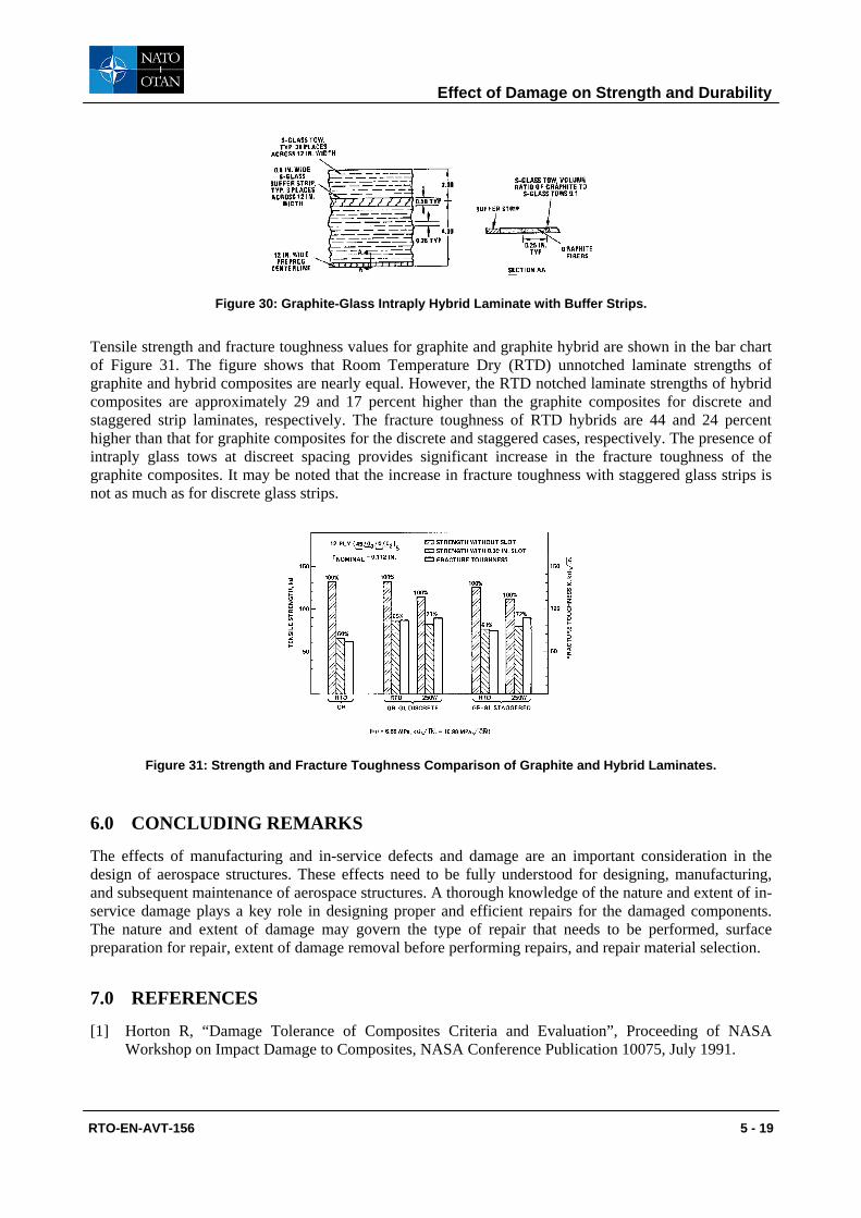
Figure 30: Graphite-Glass Intraply Hybrid Laminate with Buffer Strips.
Tensile strength and fracture toughness values for graphite and graphite hybrid are shown in the bar chart of Figure 31. The figure shows that Room Temperature Dry (RTD) unnotched laminate strengths of graphite and hybrid composites are nearly equal. However, the RTD notched laminate strengths of hybrid composites are approximately 29 and 17 percent higher than the graphite composites for discrete and staggered strip laminates, respectively. The fracture toughness of RTD hybrids are 44 and 24 percent higher than that for graphite composites for the discrete and staggered cases, respectively. The presence of intraply glass tows at discreet spacing provides significant increase in the fracture toughness of the graphite composites. It may be noted that the increase in fracture toughness with staggered glass strips is not as much as for discrete glass strips.
Figure 31: Strength and Fracture Toughness Comparison of Graphite and Hybrid Laminates.
6.0 CONCLUDING REMARKS
The effects of manufacturing and in-service defects and damage are an important consideration in the design of aerospace structures. These effects need to be fully understood for designing, manufacturing, and subsequent maintenance of aerospace structures. A thorough knowledge of the nature and extent of in-service damage plays a key role in designing proper and efficient repairs for the damaged components. The nature and extent of damage may govern the type of repair that needs to be performed, surface preparation for repair, extent of damage removal before performing repairs, and repair material selection.
7.0 REFERENCES
[1] Horton R, “Damage Tolerance of Composites Criteria and Evaluation”, Proceeding of NASA Workshop on Impact Damage to Composites, NASA Conference Publication 10075, July 1991.
Effect of Damage on Strength and Durability
RTO-EN-AVT-156 5 - 19

[2] Ramkumar R. L, “Effects of Uniform Porosity on AS/3501-6 Graphite/Epoxy Laminates”, Presented at 7th Symposium on Composite Materials: Testing and Design, Philadelphia, PA, April 1984.
[3] Altman J, et. al, “Advanced Composite Serviceability Program”, AFWAL-TR-80-4092, July 1980.
[4] Ratwani M. M, “Repair/Refurbishment of Military Aircraft” AGARD Lecture Series 206, Aging Combat Aircraft Fleets- Long Term Implications, 1996.
[5] Ratwani M. M and Kan H. P, “Compression Fatigue Analysis of Fiber Composites” Naval Air Development Center Report, NADC -78049-60, September 1979.
[6] Whitehead R, Deo R. B and Demuts E, “Assessment of Damage Tolerance in Composites”, Composites Structures, 4(1985) pp. 45-58.
[7] Porter T. R, “Evaluation of Flawed Composite Structural Components under Static and Cyclic Loading”, NASA-CR-135403, February 1979.
[8] Porter T. R, “Environmental Effects on Defect Growth in Composite Materials”, NASA-CR-165213, January 1981.
[9] Porter T. R, “Compression and Compression Testing of Composite Laminates”, NASA-CR-168023, July 1982.
[10] Labor J. D and Bhatia N. M, “Impact Resistance of Graphite and Hybrid Configurations”, Proceedings of Fourth Conference on Fibrous Composites in Structural Design, San Diego, California, November 1978.
[11] Bhatia N M, “Impact Damage Tolerance of Thick Graphite/Epoxy Laminates”, Report No. NADC-79038-60, January 1979.
[12] Ramkumar R. L, “Composite Impact Damage Susceptibility”, Report No. NADC-79068-60, January 1981.
[13] Palm T. E, “Impact Resistance and Residual Compression Strength of Composite Sandwich Panels”, Proceedings of the Eighth International Conference on Composite Materials, Honolulu, Hawaii, July 1991.
[14] Dorey G, “Impact Damage in Composite- Development, Consequences and Prevention”, Sixth International Conference on Composite Materials (and Second European Conference on Composite Materials), Volume 3, Editor F. L. Mathews, et. al, Elsevier Applied Science Publishers, London 1987.
[15] Whitehead R. S, “Certification of Primary Composite Aircraft Structures”, Presented at the 14th Symposium of the International Committee on Aeronautical Fatigue (ICAF), Ottawa, Canada, June 1997.
[16] Ramkumar R. L, Bhatia N. M, Labor J. D and Wilkes J. S, “Handbook: an Engineering Compendium on the Manufacture and Repair of Fiber Reinforced Composites”, Report No. DOT/FAA/CT-87/9, Prepared for the Department of Transportation, FAA Technical Center, Atlantic City International Airport, New Jersey, December 1986.
[17] Whitehead R. S and Demuts E, “Damage Tolerance Qualification of Composite Structures”, Proceedings of the USAF Aircraft Structural Integrity Conference, Dayton, Ohio, November 1980.
Effect of Damage on Strength and Durability
5 - 20 RTO-EN-AVT-156
[18] Byers B. A, “Behavior of Damaged Graphite/epoxy Laminates under Compression Loading"” NASA-CR-159293, August 1980.
[19] Starnes J. H. Jr. et. al., “The Effect of Impact Damage and Circular Holes on the Compressive Strength of Graphite/Epoxy Laminates”, NASA-TM-78796, October 1978.
[20] Williams J. G, et. al., “Recent Developments in the Design, Testing and Impact Damage Tolerance of Stiffened Composite Panels”, NASA-TN-80077, April 1979.
[21] Padilla V. E, “Low Velocity Damage Tolerance of Thin Graphite/Epoxy Laminates”, Proceedings of the Fifth DoD/NASA Conference on Fibrous Composites in Structural Design, New Orleans, January 1981.
[22] Rhodes M. D and Williams J. G, “Concepts for Improving the Damage Tolerance of Composite Compression Panels”, Proceedings of the Fifth DoD/NASA Conference on Fibrous Composites in Structural Design, New Orleans, January 1981.
[23] Ramkumar R. L, “Environmental Effects on Composite Damage Criticality”, Report No. NADC-79067-60, January 1980.
[24] Wilkins D. J, “A Preliminary Damage Tolerance Methodology for Composite Structures”, Workshop on Failure Analysis and Mechanisms of Failure of Fibrous composites, NASA Langley Research Center, March 1982.
[25] McCarty J. E and Roeseler, “Durability and Damage Tolerance of Large Composite Primary Structures”, Presented at Sixth DoD/NASA Conference on Fibrous Composite in Structural Design, New Orleans, January 1983.
[26] Avery J. G, “Design Manual for Impact Damage Tolerant Aircraft Structures”, AGARDogrraph No. 230, 1981.
[27] Moon Y, I and Falugi M, “A Survey of Analysis Techniques to Predict Residual Properties of Ballistically Damaged Aircraft Structures” AFWAL-TR-89-3006, April 1989.
[28] Brass J, Yamane J. R and Jacobson M. J, “Effects of Internal Blast on Combat Aircraft Structures”, Volume I, Engineer’s Manual, Technical Report AFFDL-TR-73-136, Volume I, January 1974.
[29] Massmann J, “Structural Response to Impact Damage”, AGARD Report No. 633, September 1975.
[30] Brass J, Yamane J. R and Jacobson M. J, “Effects of Internal Blast on Combat Aircraft Structures”, User’s Programmer’s Manual, Technical Report AFFDL-TR-73-136, Volume II, January 1974.
[31] Jacobson M. J, Yamane J. R and Ratwani M. M, “Effects of Internal Blast on Combat Aircraft Structures- Effects of Detonation of High Explosive Projectiles”, Technical Report AFFDL-TR-75-73, Volume II, July 1975.
[32] Dobyns A. L, “Fiber Composites Blast Response Computer Program (BR-1FC) BR-1 Code Modification and Test Program”, AFFDL-TR-78-29, JTCG/AS-76-T-008, October 1977.
[33] Herlin W and Avery, “Hydraulic Ram Structural Response Computer Program (HRSR)”, Volume I, User’s Manual, Boeing Military Airplane Company, Contract No. N60530-80-C-0242, September 1981.
Effect of Damage on Strength and Durability
RTO-EN-AVT-156 5 - 21

[34] Herlin W and Avery, “Hydraulic Ram Structural Response Computer Program (HRSR)”, Volume II, Final Report, Boeing Military Airplane Company, Contract No. N60530-80-C-0242, September 1981.
[35] Ratwani M. M, “Characterization and Residual Strength Prediction of Ballistically Damaged Aircraft Structures”, JTCG/AS-76-T-010, September 1977.
[36] Jacobson M. J, Heitz R. M and Hill F, “Survivable Composite Integral Fuel Tanks”, AFWAL-TR-85-3085, Volume III, January 1986.
[37] Burch G. T, and Avery J. G, “An Aircraft Combat Damage Model”, Volumes I and II, AFFDL-TR-70-115, November 1970.
[38] Burch G. T and Avery J. G, “An Aircraft Combat Damage Model- Design Handbook”, AFFDL-TR-70-116, November 1970.
[39] Kan H. P, and Ratwani M. M, “Statistical Modeling of Ballistic Damage and Residual Strength in Composite Structures”, AIAA Journal, 1983, pp. 594-599.
[40] Williams J. G and Rhodes M. D, “The Effect of Different Resin Materials on the Strength of Damaged Graphite/Epoxy Laminates”, ASTM Sixth Conference on Composite Materials: Testing and Design, 1981.
[41] Kennedy J. M, “Damage Tolerance of Woven Graphite/Epoxy Buffer Strip Panels”, NASA Technical Memorandum 102702, August 1990.
[42] Eisemann J. R and Kaminiski B. E, “Fracture Control for Composite Materials”, Engineering Fracture Mechanics, Vol. 4, 1972, pages 907-913.
[43] Bhatia N. M and Verette R. M, “Crack Arrestment of Laminated Composites, “ Fracture Mechanics of Composite Materials, ASTM STP 593, American Society for Testing and Materials, 1975, pages 200-214.
[44] Sendeckyj G. P, “Concepts for Crack Arrestment in Composites”, Fracture Mechanics of Composite Materials, ASTM STP 593, American Society for Testing and Materials, 1975, pages 215-226.
[45] Hess T. E, Huang S. L and Rubin H, “Fracture Control in Composite Materials Using Integral Crack Arresters”, AIAA/ASME/SAE 17th Structures, Structural Dynamics and Materials Conference, May 1976.
[46] Verette R. M and Labor J. D, “Structural Criteria for Advanced Composites”, AFFDL-TR-76-142, Volumes I and II, January 1977.
[47] Bigelow C.A, “Buffer Strips in Composites at Elevated Temperatures”, Environmental Effects on Composite Materials, Editor George Springer, Technomic Publication, 1984.
[48] Bhatia N. M, “Strength and Fracture Characteristics of Graphite-Glass Intraply Hybrid Composites”, Composite Materials: Testing and Design, ASTM STP 787, May 1981.
Effect of Damage on Strength and Durability
5 - 22 RTO-EN-AVT-156