effect of dredging and tie-rod anchor on the … · analysis are carried out • to study the...
TRANSCRIPT
EFFECT OF DREDGING AND TIE-ROD ANCHOR ON THE BEHAVIOR OF
BERTHING STRUCTURE
PREMALATHA, P.V.
PhD Research Scholar, Department of Civil Engineering, National University of Technology, Tiruchirappalli, Tamil Nadu 620015, India
MUTHUKKUMARAN, K Assistant Professor, Department of Civil Engineering, National University of Technology,
Tiruchirappalli, Tamil Nadu 620015, India [email protected]
JAYABALAN, P Professor, Department of Civil Engineering, National University of Technology,
Tiruchirappalli, Tamil Nadu 620015, India [email protected]
Abstract :
This paper deals with a numerical study on pile group supporting the berthing structures subjected to berthing/mooring forces and the forces arised due to dredging operations. A 2D Finite Element Model is developed using the geotechnical software Plaxis and is validated using the theoretical solution. Three different slopes such as 1V:3H, 1V:2H and 1V:1.5H are considered to simulate the actual field condition in berthing structure. The effect of berthing/mooring forces and the effect due to dredging operations on the pile groups are investigated with and without tie-rod anchors. The bending moment variation along the length of the piles and, the load-deflection behavior of piles are presented. Using the developed FE model, a real time berthing structure located in India is analyzed as a case study. The case study is used to assess the optimum tie-rod length required for the actual installation. This paper present the FE model description, analyses results, theoretical predictions and, the effect of dredging operations and the tie-rod in berthing structure.
Keywords: Berthing structures, dredge level, optimum length, slope, and tie rod anchor.
1. The Main Text
Berthing structures are constructed for berthing and mooring of vessels, to enable loading and unloading of cargo and for embarking and disembarking of passengers and vehicles. Berthing structures consist of a berthing head at which the ships are moored to receive or discharge their cargo. It has an approach structure connecting the berthing head to the shore and carrying the road or rail vehicles used to transport the cargo. Where minerals are handled in bulk the approach structure may carry a belt conveyor or an aerial ropeway.
Piles of a berthing structure are generally constructed in sloping ground. The behavior of such piles under lateral load is different from piles in horizontal ground. When there is a need of berthing a bigger vessel in to the existing Berthing Structure, the dredge level has to be increased. Hence the variation in dredge level results in the increase/decrease of slope of the supporting soil. This causes the lack of stiffness due to the reduction in the supporting soil. These piles will experience additional stress and strain and will result in unacceptable pile movement or stress or both. Hence tie rods are provided to support the berthing structure and this will considerably reduce the deflection when the dredge level is increased.
Premalatha, P.V. et al. / International Journal of Engineering Science and Technology (IJEST)
ISSN : 0975-5462 Vol. 3 No. 6 June 2011 5099

Numerous numerical and empirical approaches are available in literature on the response of the piles. Very few research works have been carried under lateral load and some analytical approaches have been developed in recent years for the response analysis of laterally loaded piles on sloping ground with anchorage effect in a berthing structure.
The present investigation is to study the effect of dredging on laterally loaded piles in sloping ground. The results are obtained for different loads and different level of dredging and compared by plotting load deflection curves obtained from finite element modeling by using PLAXIS. From the analysis it is found that the increase in dredge level increases the deflection of the structure which is to be arrested. Hence tie rods are provided and the behavior of structure for various different slopes is studied.
Further a case study is done in arriving at the optimum length of tie rod anchor using the properties of material obtained from a typical berthing structure in Chennai port trust. These properties are used as input parameter for the finite element modeling.
For this study, the modeling is done using a plane strain finite element approach. Plane strain analysis is the most straightforward of the finite element approaches and allows good representation of the pile group configuration and geometry, without being unduly complicated.
2. Literature Survey
Reese and Matlock (1960) gave a generalized solution for the laterally loaded pile. Basic equations and method of computations were given for both elastic and rigid behavior. Soil modulus variation with depth in different forms was considered.
Broms (1964a, 1964b) developed solutions for the ultimate lateral resistance of a pile assuming the distribution of lateral soil pressure and considering static of the problem. Also two modes of failure and yielding of the soil along the length of the pile were considered.
Poulos and Davies (1980) modified the elastic solution to account for nonlinearity using yield factors. The modulus of subgrade reaction approach was extended to account for the soil nonlinearity. This was done by introducing p-y curves (Matlock 1970, Reese et al. 1974).
Raju et al. (1985) analysed alternative systems for a berthing structure considering a combination of diaphragm wall and piles as follows: Diaphragm wall with anchor rod and deadman diaphragm wall, diaphragm wall with vertical and raker piles, diaphragm wall with vertical piles. The analysis reveals that by marginally increasing the diameter of the pile the lateral capacity of the pile is increased rather than providing tie rod anchors. But this is a case of closed type berthing structure which contains the diaphragm wall at sea side.
Muthukkumaran and Sundaravadivelu (2007) carried out a research on application of the analytical method to study the effect of dredging on piles and diaphragm wall-supported berthing structures. The piles on marine soils are loaded laterally from horizontal soil movements generated by dredging. Full-scale field test results were compared with the results obtained from finite element modeling
Not much research is carried out on the analysis of berthing structure subjected to lateral load and the effect of tie rod anchors in the berthing structure behavior. The present investigation presents a detailed study on the behavior of piles in sloping ground for various lengths of tie rod.
From the literature survey, it is observed that not much research is carried out on the analysis of berthing structure subjected to lateral load and the effect of tie rod anchors in the lateral behavior. The present study gives a detailed behavior of piles in sloping ground for various lengths of tie rod anchor.
Premalatha, P.V. et al. / International Journal of Engineering Science and Technology (IJEST)
ISSN : 0975-5462 Vol. 3 No. 6 June 2011 5100

Analysis are carried out • To study the effect of tie rod anchor by varying the dredge level of the berth. • Case study using the exact soil profile obtained from Chennai port and analyzing the optimum length of tie
rod anchor.
3. Finite element analysis:
A two dimensional finite element program PLAXIS 2D has been used to model a single frame of a berthing structure using the concept of plain strain condition.
3.1 Plane strain as two-dimensional modeling
In PLAXIS 2D, selection of plane strain conditions results in a two dimensional finite element model with only two translational degrees of freedom per node. The 15–noded triangle provides a fourth order interpolation for displacements and the numerical integration involves twelve Gauss points.
3.2 Piles and Beam elements
Plates elements in the two-dimensional finite element model are composed of beam elements (line elements) with three degrees of freedom per node: two translational degrees of freedom and one rotational degree of freedom. When using 15 noded soil elements, 5-noded beam-column elements are used. The beam column elements are based on Mindlin’s beam theory. This theory allows for beam’s deflection due to shearing as well as bending. Hence when the maximum bending moment or axial force reaches, the beam becomes plastic and starts yielding. Figure 1(a) shows the position of nodes and stress points in a 3 & 5 noded beam element and figure 1(b) shows the position of nodes and stress points in a 15 noded soil element.
(a). Position of nodes and stress points in a 3 &5 node beam element
(b). Position of Nodes and stress points in a 15 noded soil element
(c). Distribution of nodes and stress points in interface elements and connection with soil element
Fig. 1. Position of nodes and stress points
Premalatha, P.V. et al. / International Journal of Engineering Science and Technology (IJEST)
ISSN : 0975-5462 Vol. 3 No. 6 June 2011 5101

3.3 Mohr – Coulomb as soil’s model
Mohr Coulomb’s model can be considered as a first order approximation of real soil behavior. This elastic perfectly plastic model requires 5 basic input parameters, namely Young’s Modulus (E), Poisson’s ratio (µ), cohesion (c), friction angle (φ) and dilatancy angle (ψ). This is a well known and a basic soil model. The soil nodes and pile nodes are connected by bilinear Mohr-Coulomb interface elements. This allows an approximate representation of the development of lateral resistance with relative soil-pile movement and ultimately the full limiting soil pressure acting on the piles.
3.4 Mesh Generation
When the geometry model is complete, the finite element model (or mesh) can be generated. PLAXIS allows for a fully automatic mesh generation procedure, in which the geometry is divided into elements of the basic element type and compatible structural elements, if applicable. The mesh generation takes full account of the position of points and lines in the geometry model, so that exact position of layers, loads and structures is accounted for in the finite element mesh. The generation process is based on a robust triangulation principle that searches for optimised triangles and which results in an unstructured mesh. Unstructured meshes are not formed from regular patterns of elements. The numerical performance of these meshes, however, is usually better than structured meshes with regular arrays of elements. In addition to the mesh generation itself, a transformation of input data from the geometry model to the finite element mesh is made.
4. Theoretical analysis
Lateral deformation of piles involves large strains in the soil near the ground Surface. The lateral deflection of a laterally loaded pile at relatively low load level will increase approximately linearly with applied loads. However the overall load deflection behaviour is distinctively non-linear. The deflection under lateral load may be estimated with reasonable accuracy using subgrade reaction approach.
4.1 Subgrade reaction approach
The subgrade reaction approach by Broms (1981) is based on idealization of the soil as a series of horizontal layers, which provide spring supports. This approach is simple compared to equivalent cantilever approach in which piles are approximated to cantilevers.
The lateral deflection is often calculated using a horizontal subgrade reaction coefficient (subgrade modulus), Kh defined by terzaghi (1955), by the equation:
Kh = P / y
Where Kh- Horizontal subgrade reaction coefficient,
P - Load transferred from the pile to the surrounding soil per unit depth
y- Lateral deflection of the pile at the point considered.
4.2 Lateral deflection
Depending on the dimensionless length ηL<2 or ηL>4, two distinguished relations are given as in Eq (1) to Eq (3) by Broms (1981),
For ηL<2:
nL h
L
eH
y 2
33.1118
+
= (1)
Premalatha, P.V. et al. / International Journal of Engineering Science and Technology (IJEST)
ISSN : 0975-5462 Vol. 3 No. 6 June 2011 5102

For ηL<4:
( ) ( )( )IEn pph
Hy
52
23
4.2=
(2)
Where η is defined by the expression,
( )IEn
pp
h
51=η
(3)
Where L, e and H are defined as,
L – Effective length of the pile,
e - Eccentricity of the pile head,
H- Lateral load.
Randolph (1991) proposed the following Eq (4) for lateral deflection of the pile at the ground level,
( ) ( )IE
n
IEn
pp
hHe
pp
Hy h
53
2
52
62.143.2+=
(4)
5. Dredging effect on piles and the influence of tie rod anchors on them:
A thorough study has been done to have the information about the behavior of piles under changing slope of soil or dredging effect on piles. Three different slopes were analyzed viz 1V:1.5H, 1V:2H and 1V:3H. Tie rod has been provided on these cases and the amount of reduction in deflection is calculated. Finite element modeling is done using the 2D finite element software package PLAXIS and the results are compared with the theoretical ones.
5.1 Soil parameters
The analyses are conducted with sandy soil, represented by Mohr-coulomb model. The Mohr-Coulomb model is used for the proposed (linear elastic-plastic) model, with plastic flow governed by an associated flow rule. Values of angle of internal friction, dilatancy angle input for the dense sand and Young’s modulus (E) of soil has taken from BOWEL’S for dense sand. The values of soil properties are presented in table1.Initial stresses are generated in sand layer by specifying a constant value of Ko
=0.412. The properties of soil used in the modeling are summarized in table 1.
5.2 Structural Properties
The piles, beam and Dead man wall are represented by five noded beam-column elements. The beam elements are based on Mindlin’s beam theory. This theory allows for beam deflection due to shearing as well as bending. In addition, the element can change length when an axial force is applied. Bending (flexural rigidity) stiffness EI and axial stiffness EA are input values as calculated individually for pile, beam and dead man wall. E is considered as concrete. Thus the bending moments and shear forces resulting from the analysis are factored up by the pile spacing to obtain the bending moments and shear forces per pile. As the soil stiffness is much lower than the structural stiffness, the equivalent wall properties are effectively independent of the soil properties and do not vary with depth. The structural member properties for pile, beam and tie rod are presented in table 2.
Premalatha, P.V. et al. / International Journal of Engineering Science and Technology (IJEST)
ISSN : 0975-5462 Vol. 3 No. 6 June 2011 5103

5.3 Soil-structure interface
Fifteen noded soil elements and five noded structural elements are connected with five pairs of interface elements. In the figure 1 (c) the interface elements are shown to have a finite thickness, but in the finite element formation the coordinates of each node pair are identical, which means that the element has a zero thickness. Each interface has assigned to it a virtual thickness which is an imaginary dimension used for obtaining the material properties of the interface. The virtual thickness is defined as the virtual thickness factor times the average element size. The average element size is determined by the global coarseness for the mesh generation. The stiffness matrix for interface element is obtained using Newton-cotes integration points. The position of these integration points (or stress points) coincides with the position of the node pairs.
5.4 Analysis sequence
A finite element programme PLAXIS 2D version 8 has been used to model the frame. The analyses are carried out in total stresses by generating initial stresses using the undrained parameters of soil. The analysis is carried out for various loads and for the following cases.
1. Subjected to Lateral Load for a 2D berthing structure of slope 1V:3H 2. Subjected to Lateral Load for a 2D berthing structure of slope 1V:2H 3. Subjected to Lateral Load for a 2D berthing structure of slope 1V:1.5H 4. Comparison studies for all slopes considering tie rod and without tie rod
5.5 Results and Discussions
5.5.1 Lateral Load behavior
The lateral load behaviour of the pile was studied by using Lateral load-deflection curves. The curves were drawn between the lateral load applied and the lateral deflection at first left pile head in the model. Lateral load was also applied at the same point in pull direction. The analysis is carried out for various loads and sloping ground of 1V:1.5H, 1V:2H and 1V:3H.
Figure 2 shows 2D deformed mesh of a single frame of berthing structure for slopes 1V:3H. The distance between the piles is 7.5m and 35m long. Figure 3, 5,& 7 shows the load deflection curves for front pile in sloping ground 1V:3H, 1V:2H and 1V:1.5H respectively. The deflection is measured at the top of the pile. The curves are plotted for various different loads viz 100kN, 500kN, 750kN and 1000kN.
Figure 4, 6 and 8 shows the bending moment variation along the depth for various loads 250 kN, 500 kN, 750kN and 1000 kN without tie rod anchor for slopes 1V:3H, 1V:2H and 1V:1.15H respectively. Figure 10 shows the comparison of bending moments for all the slopes without tie rod anchor. When the slope is increased from 1V:1.5H to 1V:2H, it is observed that the depth of fixity decreases from -22.5m to -17.5m. When the slope is increased from 1V:2H to 1V:3H, it is observed that the depth of fixity decreases from -17.5m to -13m. For horizontal ground, the depth of fixity is the least and at -7m
Fig. 2. Deformed mesh (slope1V:3H)
Premalatha, P.V. et al. / International Journal of Engineering Science and Technology (IJEST)
ISSN : 0975-5462 Vol. 3 No. 6 June 2011 5104

Fig. 3. Lateral load vs lateral deflection (slope1V:3H)
Fig. 4. Bending moment variation (Slope 1V:3H)
0
0.2
0.4
0.6
0.8
1
1.2
-0.01 0 0.01 0.02 0.03 0.04 0.05 0.06
Mul
tipl
ier
Deflection (m)
Slope 1:3 & P=100kN
Slope 1:3 & P=500kN
Slope 1:3 & P=750kN
Slope 1:3 & P=1000kN
-35
-30
-25
-20
-15
-10
-5
0
-2000 -1500 -1000 -500 0 500 1000
Dept
h (m
)
Bending Moment kN-m
P=100kN
P=500kN
P=750kN
P=1000kN
Premalatha, P.V. et al. / International Journal of Engineering Science and Technology (IJEST)
ISSN : 0975-5462 Vol. 3 No. 6 June 2011 5105

Fig. 5. Lateral load vs lateral deflection (slope 1V:2H)
Fig. 6. Bending moment variation (Slope 1V:2H)
0
0.2
0.4
0.6
0.8
1
1.2
-0.02 0 0.02 0.04 0.06 0.08 0.1 0.12
Mu
ltip
lier
Deflection (m)
Slope 1:2 & P=100kN
Slope 1:2 & P=500kN
Slope 1:2 & P=750kN
Slope 1:2 & P=1000kN
-35
-30
-25
-20
-15
-10
-5
0
-3000 -2000 -1000 0 1000 2000
Dept
h (m
)
Bending Moment kN-m
P=100kN
P=500kN
P=750kN
P=1000kN
Premalatha, P.V. et al. / International Journal of Engineering Science and Technology (IJEST)
ISSN : 0975-5462 Vol. 3 No. 6 June 2011 5106

Fig. 7. Lateral load vs lateral deflection (slope 1V:1.5H)
Fig. 8. Bending moment variation (slope 1V:1.5H)
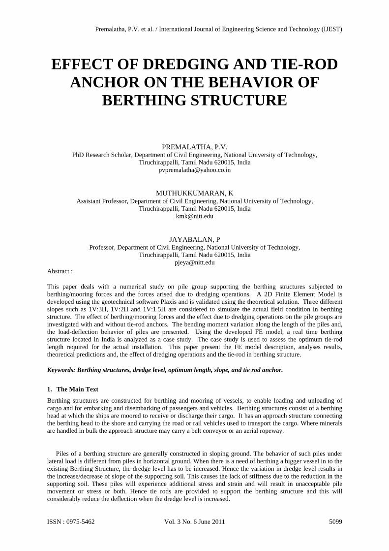
Figure 9 shows the comparison of displacements for 1V:1.5H, 1V:2H, 1V:3H sloping ground for 1000kN without tie rod. From the results it is observed that the displacements in 1V:3H sloping ground have the least deflection. When the slope is increased from 1V:3H to 1V:2H, the deflection increases from 0.047m to 0.095m which is almost double. When the slope is increased from 1V:2H to 1V:1.5H, the deflection is increased from 0.095m to 0.177m which is about an increase of 89.5%.
0
0.2
0.4
0.6
0.8
1
1.2
-0.05 0 0.05 0.1 0.15 0.2
Mul
tipl
ier
Deflection (m)
Slope 1:1.5 & P=100kN
Slope 1:1.5 & P=500kN
Slope 1:1.5 & P=750kN
Slope 1:1.5 & P=1000kN
-35
-30
-25
-20
-15
-10
-5
0
-3000 -2000 -1000 0 1000 2000
Dept
h(m
)
Bending Moment (kN-m)
P=100kN
P=500kN
P=750kN
P=1000kN
Premalatha, P.V. et al. / International Journal of Engineering Science and Technology (IJEST)
ISSN : 0975-5462 Vol. 3 No. 6 June 2011 5107
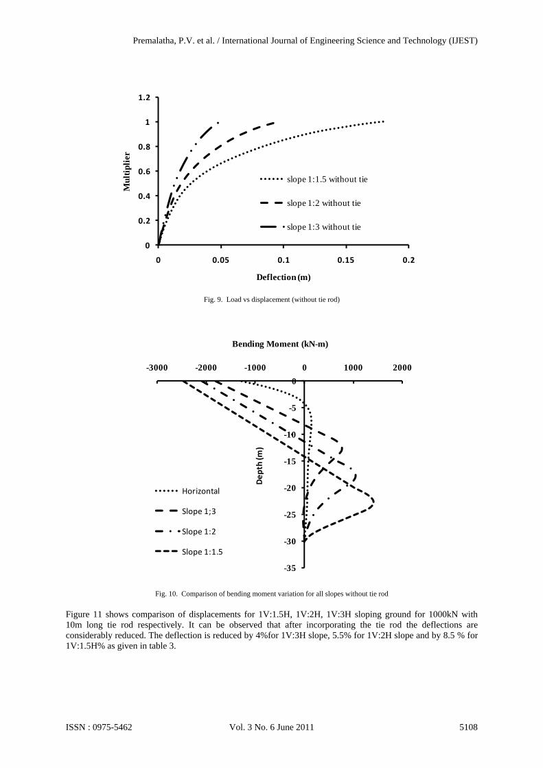
Fig. 9. Load vs displacement (without tie rod)
Fig. 10. Comparison of bending moment variation for all slopes without tie rod
Figure 11 shows comparison of displacements for 1V:1.5H, 1V:2H, 1V:3H sloping ground for 1000kN with 10m long tie rod respectively. It can be observed that after incorporating the tie rod the deflections are considerably reduced. The deflection is reduced by 4%for 1V:3H slope, 5.5% for 1V:2H slope and by 8.5 % for 1V:1.5H% as given in table 3.
0
0.2
0.4
0.6
0.8
1
1.2
0 0.05 0.1 0.15 0.2
Mul
tipl
ier
Deflection (m)
slope 1:1.5 without tie
slope 1:2 without tie
slope 1:3 without tie
-35
-30
-25
-20
-15
-10
-5
0
-3000 -2000 -1000 0 1000 2000
Dept
h (m
)
Bending Moment (kN-m)
Horizontal
Slope 1;3
Slope 1:2
Slope 1:1.5
Premalatha, P.V. et al. / International Journal of Engineering Science and Technology (IJEST)
ISSN : 0975-5462 Vol. 3 No. 6 June 2011 5108
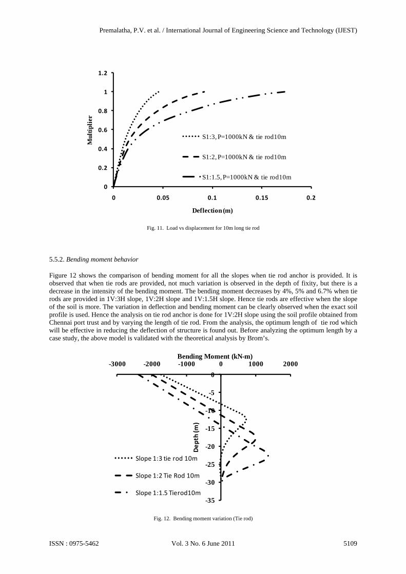
Fig. 11. Load vs displacement for 10m long tie rod
5.5.2. Bending moment behavior
Figure 12 shows the comparison of bending moment for all the slopes when tie rod anchor is provided. It is observed that when tie rods are provided, not much variation is observed in the depth of fixity, but there is a decrease in the intensity of the bending moment. The bending moment decreases by 4%, 5% and 6.7% when tie rods are provided in 1V:3H slope, 1V:2H slope and 1V:1.5H slope. Hence tie rods are effective when the slope of the soil is more. The variation in deflection and bending moment can be clearly observed when the exact soil profile is used. Hence the analysis on tie rod anchor is done for 1V:2H slope using the soil profile obtained from Chennai port trust and by varying the length of tie rod. From the analysis, the optimum length of tie rod which will be effective in reducing the deflection of structure is found out. Before analyzing the optimum length by a case study, the above model is validated with the theoretical analysis by Brom’s.
Fig. 12. Bending moment variation (Tie rod)
0
0.2
0.4
0.6
0.8
1
1.2
0 0.05 0.1 0.15 0.2
Mul
tipl
ier
Deflection (m)
S1:3, P=1000kN & tie rod10m
S1:2, P=1000kN & tie rod10m
S1:1.5, P=1000kN & tie rod10m
-35
-30
-25
-20
-15
-10
-5
0
-3000 -2000 -1000 0 1000 2000
Dept
h (m
)
Bending Moment (kN-m)
Slope 1:3 tie rod 10m
Slope 1:2 Tie Rod 10m
Slope 1:1.5 Tierod10m
Premalatha, P.V. et al. / International Journal of Engineering Science and Technology (IJEST)
ISSN : 0975-5462 Vol. 3 No. 6 June 2011 5109
5.6 Validation of the finite element model
Theoretical displacements have been calculated from the theoretical analysis and that result is used to compare with FEA results to verify PLAXIS model.
Lateral Deflection from Broms Equation
For Grade 40 concrete, Ep is taken equal to 5000√fck=31.62x10⁶ kN/m2
Lateral dimension of the pile is 1m and I=πd4/64=0.049mm4
Hence EpIp=1.55x10⁶ kNm2
For 1000 kN
( ) ( )( )my
y
0896.0
610004.2
1055.120 52
23
=
×
×=×
Similarly
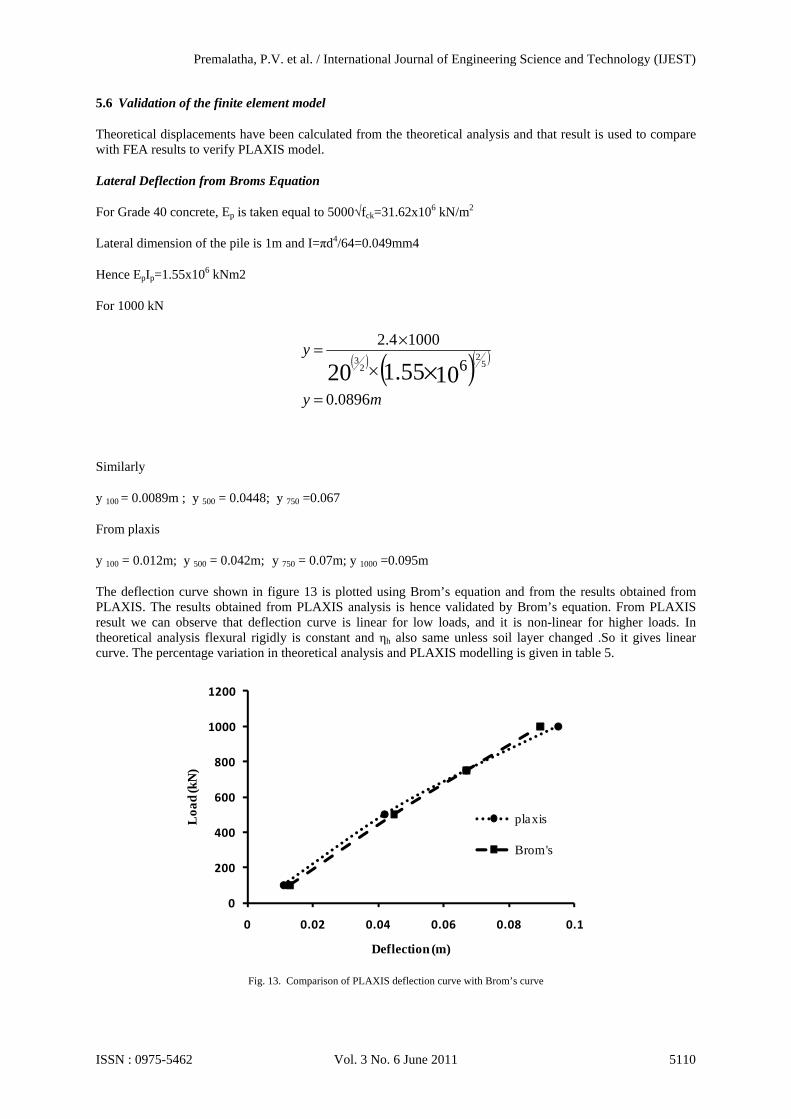
y 100 = 0.0089m ; y 500 = 0.0448; y 750 =0.067
From plaxis
y 100 = 0.012m; y 500 = 0.042m; y 750 = 0.07m; y 1000 =0.095m
The deflection curve shown in figure 13 is plotted using Brom’s equation and from the results obtained from PLAXIS. The results obtained from PLAXIS analysis is hence validated by Brom’s equation. From PLAXIS result we can observe that deflection curve is linear for low loads, and it is non-linear for higher loads. In theoretical analysis flexural rigidly is constant and ηh also same unless soil layer changed .So it gives linear curve. The percentage variation in theoretical analysis and PLAXIS modelling is given in table 5.
Fig. 13. Comparison of PLAXIS deflection curve with Brom’s curve
0
200
400
600
800
1000
1200
0 0.02 0.04 0.06 0.08 0.1
Loa
d (k
N)
Deflection (m)
plaxis
Brom's
Premalatha, P.V. et al. / International Journal of Engineering Science and Technology (IJEST)
ISSN : 0975-5462 Vol. 3 No. 6 June 2011 5110

6. Case study - berthing structure in Chennai port:
6.1 Properties of Sand and Model Pile
A finite element program PLAXIS 2D Version-8 has been used to model the frame. The analyses are carried out in total stresses by generating initial stresses using the undrained parameters of soil. The analysis is carried out for various loads viz 250kN, 500kN, 750kN, 1000kN and for the following cases:
Case 1: Berthing Structure Subjected to lateral load without tie rod anchor. Case 2: Berthing Structure Subjected to lateral load with tie rod anchor of length 6m, 8m, 10m, 14.5m, 18m, 20m and 22m in layered soil of different properties.
6.2 Bore hole data
Typical bore hole data are collected from Chennai port trust for getting the layered soil profile. The depth vs SPT N values are plotted in the figure 14 and observed that the bore hole 8 is the critical bore hole. Soil parameters arrived for this critical bore hole data is considered for the analysis. Table 6 gives the various layers of the soil profile and their properties.
Fig. 14. Depth vs SPT N values
6.3. Results and comments
Figure 15 shows the effective mean stresses generated in the berthing structure with tie rod anchor. The center to centre distance between the piles is 7.5m and the pile is 35m long as in the previous case. The length of tie rod is 14.5m with a diameter of 115mm. Total number of element is 464, node is 1208, node stress points 1392. The soil stratum is idealized by 15 noded triangular elements with elastic-plastic Mohr Coulomb model and the structural elements are idealized by beam element
0
5
10
15
20
25
30
35
40
0 10 20 30 40 50 60 70
Dep
th in
(m
)
SPT N values (number of blows)
BH1
BH2
BH3
BH4
BH5
BH6
BH7
BH8
Premalatha, P.V. et al. / International Journal of Engineering Science and Technology (IJEST)
ISSN : 0975-5462 Vol. 3 No. 6 June 2011 5111
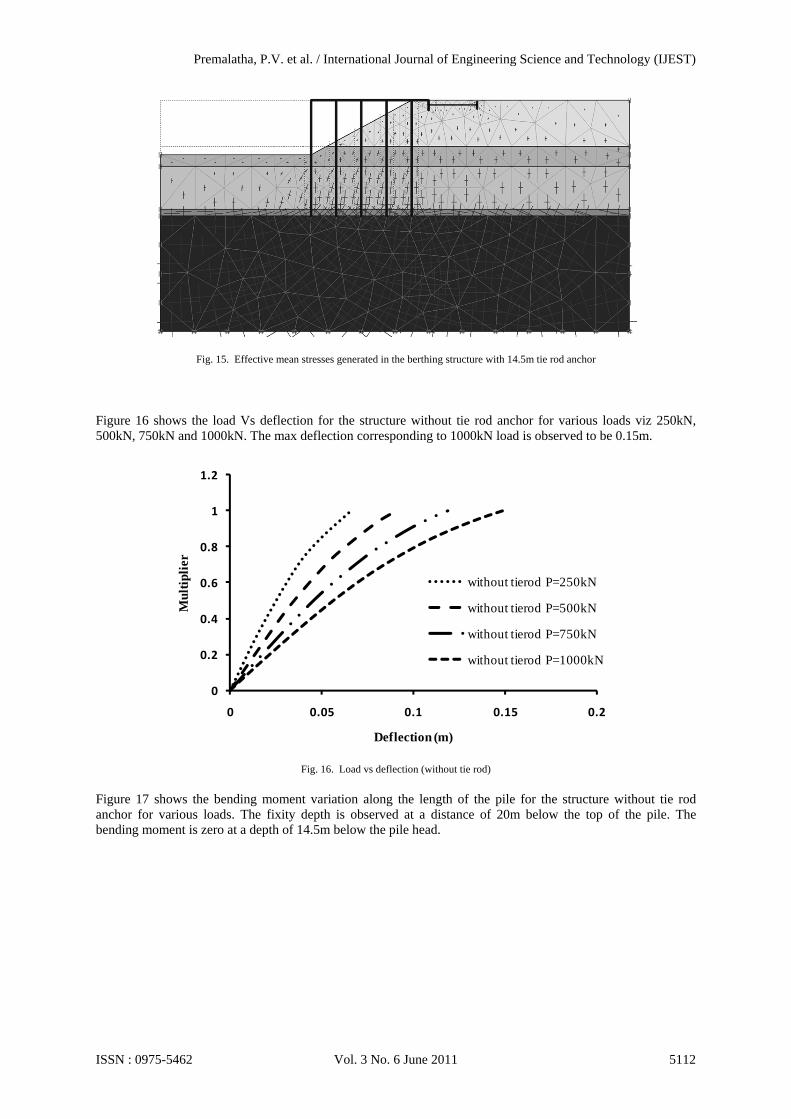
Fig. 15. Effective mean stresses generated in the berthing structure with 14.5m tie rod anchor
Figure 16 shows the load Vs deflection for the structure without tie rod anchor for various loads viz 250kN, 500kN, 750kN and 1000kN. The max deflection corresponding to 1000kN load is observed to be 0.15m.
Fig. 16. Load vs deflection (without tie rod)
Figure 17 shows the bending moment variation along the length of the pile for the structure without tie rod anchor for various loads. The fixity depth is observed at a distance of 20m below the top of the pile. The bending moment is zero at a depth of 14.5m below the pile head.
0
0.2
0.4
0.6
0.8
1
1.2
0 0.05 0.1 0.15 0.2
Mul
tipl
ier
Deflection (m)
without tierod P=250kN
without tierod P=500kN
without tierod P=750kN
without tierod P=1000kN
Premalatha, P.V. et al. / International Journal of Engineering Science and Technology (IJEST)
ISSN : 0975-5462 Vol. 3 No. 6 June 2011 5112

Fig. 17. Bending moment variation (without tie rod)
Figure 18 shows the lateral load - deflection curve for a berthing structure with 14.5m tie rod. From figure 15 and figure 18, it can be seen, that the deflection is reduced by 19.5% by providing a tie rod of length 14.5m.
Fig. 18. Load vs deflection (with 14.5m tie rod)
Figure 19 shows the bending moment variation along the pile depth for a 14.5m tie rod anchor. The fixity depth is observed at a distance of 20m below the top of the pile. The bending moment is zero at a depth of 14.5m below the pile head. It is observed that there is no variation in the depth of fixity as compared to the case without tie rod anchor but the bending moment is reduced by 11.8%.
-40
-35
-30
-25
-20
-15
-10
-5
0
-4000 -3000 -2000 -1000 0 1000 2000 3000
Dep
th (
m)
Bending Moment (kN-m)
P=250kN
P=500kN
P=750kN
P=1000kN
0
0.2
0.4
0.6
0.8
1
1.2
0 0.05 0.1 0.15
Mul
tipi
er
Deflection (m)
l=14.5mP=250kN
l=14.5mP=500kN
l=14.5mP=750kN
l=14.5mP=1000kN
Premalatha, P.V. et al. / International Journal of Engineering Science and Technology (IJEST)
ISSN : 0975-5462 Vol. 3 No. 6 June 2011 5113

Fig. 19. Bending moment variation (with 14.5m tie rod)
Figure 20 shows the max deflection for various length of tie rod anchor. It is observed that the deflection is reduced by 8.72% when a tie rod of 6m length is provided. The displacement is reduced to 10.07%, 11.4%, 14.09%, and 15.43% when the length of tie rod provided is increased to 8m, 10m, 14.5m, and 18m correspondingly. Beyond 18m, the further increase in length of tie rod to 20m, 22m and so on does not show any percentage reduction in the displacement. The deflection is stable at 0.126m for 18m, 20m and 22m length of tie rod anchor. Hence optimum length is arrived as 18m for this particular case which reduces the deflection of the structure effectively.
Fig. 20. Length of tie rod vs deflection in a layered soil
Figure 21 shows the force vs length of tie rod in a layered soil. It can be observed that the increase in force transferred to tie rod is 12.62%, 15.83%, 18.82% and 10.48% when the length is increased from 6m to 8m, 10m, 14.5m and 18m. Beyond the optimum length of 18m the increase in force transferred to tie rod increases only by 1.8% and 1.6%.
-40
-35
-30
-25
-20
-15
-10
-5
0
-4000 -3000 -2000 -1000 0 1000 2000
Dept
h (m
)
Bending Moment (kN-m)
l=14.5mP=250kN
l=14.5mP=500kN
l=14.5mP=750kN
l=14.5mP=1000kN
0.12
0.125
0.13
0.135
0.14
0.145
0.15
0.155
0 5 10 15 20 25
Def
lect
ion
(m)
Length of tie rod (m)
Premalatha, P.V. et al. / International Journal of Engineering Science and Technology (IJEST)
ISSN : 0975-5462 Vol. 3 No. 6 June 2011 5114

Fig. 21. Length of tie rod vs force in tie rod
7. Conclusion
• The lateral deflection of Berthing structure due to mooring/pulling force is more when compared to berthing force.
• Among the three slopes (viz 1V:3H, 1V:2H and 1V:1.5H), slope 1V:3H is normally stable by itself and has the least deflection. From the deformed mesh it is observed that the soil movement is much greater in top layers of sandy soil. And it can be observed that the failure zone is like a circular slip failure.
• When the dredge level is increased from 1V:3H to 1V:2H and further to 1V:1.5H, the deflection of the structure increases by 102% and 89.5% respectively. Hence tie rods are essential to reduce this increase in deflection.
• The effect of tie rod plays a major role in reducing the deflection of the berthing structure thereby reducing the length of pile, material and reinforcement used for construction.
• The variation in location of these anchors through finite element modeling can be very helpful in analyzing the behavior of piles in such berthing structures and an economical design too.
• From the case study, it is observed that the deflection is reduced by 8.72%, 10.07%, 11.4%, 14.09%, and 15.43% when the length of tie rod is increased in sequence from 6m, 8m, 10m, 14.5m, and 18m correspondingly. After 18m, when the length is increased to 20m, 22m and so on there is no percentage reduction in the displacement and increasing the tie rod length beyond this will not reduce the deflection of the structure. Hence optimum length is arrived as 18m for this particular case which reduces the deflection of the structure effectively.
Reference
[1] Broms (1964a): The lateral resistance of piles in cohesive soils. Journal of the Soil Mechanics and Foundation Div., 90(2), 27 - 63. [2] Broms (1964b). The lateral resistance of piles in cohesionless soil. Journal of the Soil Mechanics and Foundation Div., 90(3), 123 –
156 [3] Broms Bengt, B. (1981): Precast piling practice. Text book, T.Telford, London. [4] Joseph E.Bowles (1997): Foundation Analysis and Design. Text book, Fifth edition. New York, USA:McGraw Hill company. [5] Matlock, H., and Reese, L.C (1960): Generalized solution for the laterally loaded piles Journal of the Soil Mechanics and Foundation
Div., ASCE, 86(5), 63 - 91. [6] Muthukkumaran K., and Sundaravadivelu R. (2007): Numerical modeling of dredging effect on berthing structure. Acta Geotechnica
International Journal of Geoengineering 2 pp249–259 [7] Poulos, H.G., and Davies, E.H (1980): Pile foundation and design. Text book. John Wiley and Sons, New York. [8] Raju, V.S., Sundaravadivelu, R., and Gandhi,.S.R.(1985): Analysis of alternative systems for a Berthing Structure”, Proceedings of
First National Conference on Harbour and Dock Engineering, IIT Bombay, 195-205. [9] Randolph M.F. (1991): Lateral capacity and performance of single piles, Lecture note 7, Dept. of Civil and Environmental
Engineering, The University of Western Australia. [10] Terzaghi K. (1955): Evaluation of coefficient of subgrade reaction, Geotechnics vol.3. [11] Tomlinson, M J, (1987): Pile Design and Construction Practice. Text book. Third edition, a view point publication.
0
20
40
60
80
100
120
140
160
0 5 10 15 20 25
For
ce in
tie
rod
(kN
)
Length of tie rod (m)
Premalatha, P.V. et al. / International Journal of Engineering Science and Technology (IJEST)
ISSN : 0975-5462 Vol. 3 No. 6 June 2011 5115