effect of exhaust gas recirculation on emissions …
TRANSCRIPT

NASA TECHNICAL
MEMORANDUM
NASA TM X-3464
X
EFFECT OF EXHAUST GAS RECIRCULATION
ON EMISSIONS FROM A FLAME-TUBE
COMBUSTOR USING LIQUID JET A FUEL
Cecil J. Marek and Robert R. Tacina
Lewis Research Center
Cleveland, Ohio 44135«*"? .
NATIONAL AERONAUTICS AND SPACE ADMINISTRATION • WASHINGTON, D. C. • DECEMBER 1976
https://ntrs.nasa.gov/search.jsp?R=19770007089 2020-03-22T12:20:29+00:00Z

1. Report No.
NASA TMX-34642. Government Accession No.
4. Title and Subtitle EFFECT OF EXHAUST GAS RECIRCULATION ON
EMISSIONS FROM A FLAME -TUBE COMBUSTOR USINGLIQUID JET A FUEL
7. Author(s)
Cecil J. Marek and Robert R.
9. Performing Organization Name and Address
Lewis Research CenterNational Aeronautics and SpaceCleveland, Ohio 44135
Tacina
Administration
12. Sponsoring Agency Name and Address
National Aeronautics and Space AdministrationWashington, D.C. 20546
3. Recipient's Catalog No.
5. Report DateDecember 1976
6. Performing Organization Code
8. Performing Organization Report No.
E-880310. Work Unit No.
505-0311. Contract or Grant No.
13. Type of Report and Period Covered
Technical Memorandum14. Sponsoring Agency Code
15. Supplementary Notes
16. Abstract
The effects of uncooled exhaust gas recirculation as an inert diluent on emissions of oxides ofnitrogen (NO + NO2) and on combustion efficiency were investigated. Ratios of recirculatedcombustion products to inlet airflow were varied from 10 to 80 percent by using an inlet airejector nozzle. Liquid Jet A fuel was used. The flame-tube combustor was 10.2 cm in diam-eter. It was operated with and without a flameholder present. The combustor pressure wasmaintained constant at 0. 5 MPa (5 atm). The equivalence ratio was varied from 0.3 to 1.0.The inlet air temperature was varied from 590 to 800 K, and the reference velocity from10 to 30 m/sec. Increasing the percent recirculation from 10 to 25 had the following effects:(1) the peak NOV emission was decreased by 37 percent, from 8 to 5 g NO9Ag fuel, at an inlet
X *air temperature of 590 K and a reference velocity of 15 m/sec; (2) the combustion efficiencywas increased, particularly at the higher equivalence ratios; and (3) for a high combustion ef-ficiency of greater than 99.5 percent, the range of operation of the combustor was nearlydoubled in terms of equivalence ratio. Increasing the recirculation from 25 to 50 percent didnot change the emissions significantly.
17. Key Words (Suggested by Author(s))
Gas turbine combustorRecirculationEmissions
19. Security Ctassif. (of this report)
Unclassified
18. Distribution Statement
Unclassified - unlimitedSTAR Category
20. Security Classif. (of this page)
Unclassified
07
21. No. of Pages
25
22. Price'
$3.50
* For sale by the National Technical Information Service, Springfield, Virginia 22161

EFFECT OF EXHAUST GAS RECIRCULATION ON EMISSIONS FROM A
FLAME-TUBE COMBUSTOR USING LIQUID JET A FUEL
by Cecil J. Marek and Robert R. Tacina
Lewis Research Center
SUMMARY
The effects of uncooled exhaust gas recirculation as an inert diluent on emissionsof oxides of nitrogen (NO + NOg) and on combustion inefficiency were measured. Ratiosof recirculated combustion products to inlet airflow were varied from 10 to 80 percent.Liquid Jet A fuel was used. The combustor pressure was maintained at 0. 5 megapascal.The equivalence ratio was varied from 0.3 to 1.0. The inlet air temperature was variedfrom 590 to 800 K, and the reference velocity from 10 to 30 meters per second. Datawere obtained with and without a flameholder.
Increasing the percent recirculation from 10 to 25 percent had the following effects:(1) the peak NOX emission was decreased by 37 percent, from 8 to 5 grams of NOg perkilogram of fuel, at an inlet air temperature of 590 K and a reference velocity of 15 me-ters per second; (2) the combustion efficiency was increased, particularly at the higherequivalence ratios; (3) for a high combustor efficiency of greater than 99.5 percent, therange of operation of the combustor was nearly doubled in terms of equivalence ratio.Increasing the recirculation from 25 to 50 percent did not change the emissions signifi-cantly .
Cooling by heat loss appeared to be the major reason for the reduction in NO emis-Jv
sions by recirculation. Nonthermal effects such as increased mixing intensity, reducedresidence time, and oxygen atom concentration reduction appeared to be present, buttheir role could not be quantitatively defined.
INTRODUCTION
Exhaust gas recirculation was used on a flame-tube combustor to determine its ef-fect on exhaust emissions of oxides of nitrogen (NO ), carbon monoxide, and unburnedhydrocarbons.
The high combustor inlet air temperatures and pressures of advanced high-

pressure-ratio engines increase the emissions of NC5 pollutants. Nitrogen oxide for-X
mation is strongly temperature and time dependent. Combustor designs which have beeneffective in reducing NO emissions involve lower primary zone flame temperatures
X.
and shorter primary zone residence times. A simple technique for reducing NO__ emis-X
sions is water injection into the primary zone. With this technique oxygen dilutionoccurs, and the flame temperature is reduced by the high latent and sensible heat ca-pacity of the water diluent. Combustor tests (refs. 1 and 2) have demonstrated the de-crease in NO emissions effected by water injection. However, water injection pre-sents problems in practical applications. The added weight and storage volume,demineralization to prevent turbine deposits, and antifreeze protection must all beconsidered. Using exhaust combustion products for combustor primary zone dilutionwill avoid the cycle penalties of water injection.
External recirculation has reduced levels of nitrogen oxides in boilers and auto-motive Rankine cycle combustors (refs. 3 to 5). A recirculation ratio of 50 percent ofthe inlet airflow has reduced smoke formation and lowered flame luminosity with animprovement in combustion efficiency (refs. 6 and 7). The results of references 3 to 7were obtained with external, cooled recirculation gas formed by exhaust products ductedback to the inlet and mixed with1 the inlet air.
In a gas turbine no heat is removed from the exhaust stream. The purpose of thisexperiment was to determine whether a significant reduction in nitrogen oxides occursbecause of the decrease in oxygen, concentration and the decreased primary zone resi-dence time with minimal heat removal from the exhaust stream. The reduction in oxy-gen concentration reduces the oxygen atom concentration, which is the major contributorto the NO production reactions. The oxygen atom overshoot discussed in reference 8,
X *
which results in radical concentrations above thermal equilibrium levels, should bediminished. The residence time in the primary zone is shortened because of the in-creased mass flow rate with recirculation.
The experiments described in this report were performed in a simple flame-tubecombustor. For measurements of the recirculation rates, external recirculation wasused, where the exhaust products were ducted back into the air inlet. Thus, oxygendilution was completed by mixing the inlet air and recirculated gases before additionalfuel was injected. Fuel droplet evaporation was rapid because of the elevated tempera-ture of the mixture. Tests were performed with and without a flame stabilizer cone.The exhaust gases were recirculated by an ejector nozzle driven by the inlet combustionair. The recirculation ratio R, the ratio of recirculated combustion products to inletairflow, was varied from 10 to 80 percent by changing the ejector nozzle size. Refer-ence velocity was varied from 10 to 30 meters per second, and the inlet air temperaturewas varied from 590 to 800 K. The combustor pressure was held constant at 0.5 mega-pascal. Liquid Jet A fuel was used, and the equivalence ratio varied from 0.3 to 1.0.

SYMBOLS
El emission index, g/kg fuel
FARR ratio of gas sample fuel-air ratio to metered fuel-air ratio
f/a combustor fuel-air ratio, metered fuel flow/airflow
(f/a)M fuel-air ratio of air and recirculated products at mixed station M
L length of combustion zone
m0. mass flow rate of inlet airdJLX
R recirculation, percent (eq. (2))
TF equilibrium flame temperature corrected for heat losses
TV. temperature of air and recirculated exhaust products at station M
TM equilibrium temperature calculated from Tg and (f/a)M
T, inlet air temperature
Tg inlet air temperature corrected for heat loss (eq. (6))
t residence time
Upej reference velocity based on To, combustor pressure, and inlet airflow
Subscripts:
C conditions in combustor
CO carbon monoxide
eq conditions at chemical equilibrium
M conditions of mixed air and recirculated products at station M
NO_ nitrogen oxidesJi
R condition in recirculation loop
UHC unburned hydrocarbons
APPARATUS AND PROCEDURE
The test apparatus, shown in figures 1 and 2, was constructed of 10.2-centimeter -inside-diameter pipe. Inlet air was supplied at 1 megapascal and was indirectly heatedto an inlet temperature Tg of 590 to 800 K. The air passed through a control valve andthen through a converging nozzle, which acted as an ejector by pumping the exhaustgases into the inlet stream. Three different nozzles, with inside diameters of 2.03,
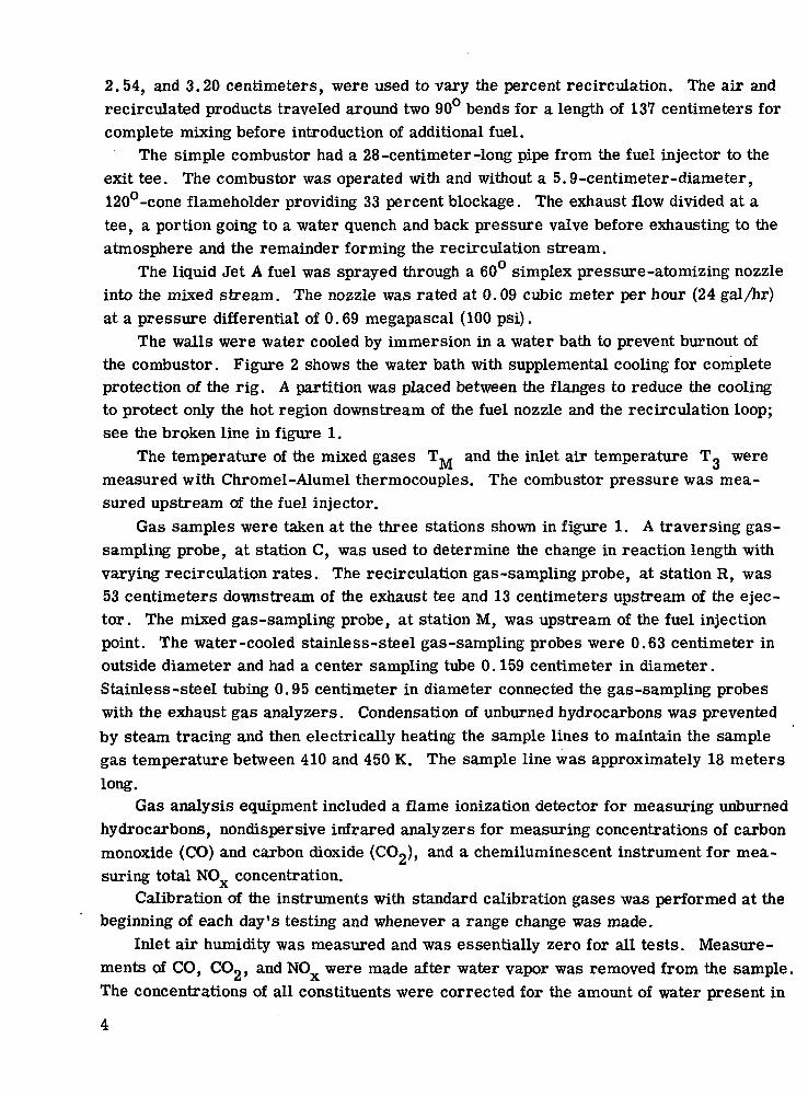
2.54, and 3.20 centimeters, were used to vary the percent recirculation. The air andrecirculated products traveled around two 90° bends for a length of 137 centimeters forcomplete mixing before introduction of additional fuel.
The simple combustor had a 28-centimeter-long pipe from the fuel injector to theexit tee. The combustor was operated with and without a 5.9-centimeter-diameter,120°-cone flameholder providing 33 percent blockage. The exhaust flow divided at atee, a portion going to a water quench and back pressure valve before exhausting to theatmosphere and the remainder forming the recirculation stream.
The liquid Jet A fuel was sprayed through a 60° simplex pressure-atomizing nozzleinto the mixed stream. The nozzle was rated at 0.09 cubic meter per hour (24 gal/hr)at a pressure differential of 0.69 megapascal (100 psi).
The walls were water cooled by immersion in a water bath to prevent burnout ofthe combustor. Figure 2 shows the water bath with supplemental cooling for completeprotection of the rig. A partition was placed between the flanges to reduce the coolingto protect only the hot region downstream of the fuel nozzle and the recirculation loop;see the broken line in figure 1.
The temperature of the mixed gases TM and the inlet air temperature T« weremeasured with Chromel-Alumel thermocouples. The combustor pressure was mea-sured upstream of the fuel injector.
Gas samples were taken at the three stations shown in figure 1. A traversing gas-sampling probe, at station C, was used to determine the change in reaction length withvarying recirculation rates. The recirculation gas-sampling probe, at station R, was53 centimeters downstream of the exhaust tee and 13 centimeters upstream of the ejec-tor. The mixed gas-sampling probe, at station M, was upstream of the fuel injectionpoint. The water-cooled stainless-steel gas-sampling probes were 0.63 centimeter inoutside diameter and had a center sampling tube 0.159 centimeter in diameter.Stainless-steel tubing 0.95 centimeter in diameter connected the gas-sampling probeswith the exhaust gas analyzers. Condensation of unburned hydrocarbons was preventedby steam tracing and then electrically heating the sample lines to maintain the samplegas temperature between 410 and 450 K. The sample line was approximately 18 meterslong.
Gas analysis equipment included a flame ionization detector for measuring unburnedhydrocarbons, nondispersive infrared analyzers for measuring concentrations of carbonmonoxide (CO) and carbon dioxide (COg), and a chemiluminescent instrument for mea-suring total NCV. concentration.
X
Calibration of the instruments with standard calibration gases was performed at thebeginning of each day's testing and whenever a range change was made.
Inlet air humidity was measured and was essentially zero for all tests. Measure-ments of CO, COg, and NOX were made after water vapor was removed from the sample.The concentrations of all constituents were corrected for the amount of water present in
the combustion products at the particular equivalence ratio. The NO., concentrationX
(ppm) is presented on the wet basis.
ANALYSIS
The calculation of combustion inefficiency from gas analysis is presented in thissection. Also, several aspects of recirculation are discussed, including the calculationof the percent recirculation and the calculation of a corrected inlet air temperature toaccount for heat loss.
Combustion Inefficiency
The combustion inefficiency is computed from the carbon monoxide and unburnedhydrocarbon measurements by the equation
percent inefficiency = 0.1 ^limc + 0.0234(EICO - EICQ ) (1)
where EIp is the emission index of unburned hydrocarbons, in grams per kilogramof fuel; EL-jQ is the emission index of carbon monoxide; and EI^Q is the calculatedchemical equilibrium carbon monoxide emission index. Only the combustion inefficiencyis reported rather than the carbon monoxide and unburned hydrocarbon measurements.
Recirculation
The percent recirculation R is defined in this report as
R = weight flow of recirculation x JQQ /2\weight flow of inlet air
Recirculation has been previously defined on the basis of stoichiometric airflow(refs. 6 and 7), airflow and fuel flow (ref. 3), and total combustion flow (ref. 4). Thedifferent values can easily be related given the overall fuel-air ratio.
External recirculation was used in this experiment so that the quantity of recircu-lated gas could be measured and the gas could be mixed with the inlet air before enteringthe combustor. The recirculation ratio was determined from gas analysis measurementsof the mixed stream, at station M.

Recir-culation
"air
Combustor
100 "air
Station
"air-TmPair
Mixedstation M
(a) Airflow schematic showing mass flow rates of air.
(f/a) majr ,(ffa) m
Combustor
Station
'air
Mixedstation M
(b) Fuel flow schematic showing mass flow rates of fuel.
From sketches (a) and (b), the ratio of fuel flow to mixed airflow at station M is
R . fmair ~100 ai a
1007
R f100 a
1+ Rmair 1+I^o~
(3)
where f/a is the metered fuel-air ratio.From measurement of CO, CO2, and unburned hydrocarbon concentration, the fuel-
air ratio of the mixed stream (f/a)M is calculated. Let FARR be the ratio of (f/a)M
to the metered fuel-air ratio f/a. Then from equation (3),
FARR =
R100
1 + R100
(4)
Solving for R gives
R = FARR1 - FARR
x 100 (5)

Equation (5) was used to calculate the percent recirculation.
Correction for Heat Loss From Recirculation Loop
The apparatus required cooling, which resulted in heat losses of from 5 to 20 percentof the heat released in combustion. The magnitude of the heat loss depended on the fuel-air ratio, percent recirculation, reference velocity, and inlet air temperature. The heatloss could be computed by comparison of the measured mixture temperature T,, withthe computed equilibrium temperature T,» at the measured fuel -air ratio (f/a)™and the inlet air temperature T,.
An adiabatic recirculation cycle was determined by computing a corrected inlettemperature to account for heat losses. The corrected inlet temperature TO was cal-culated from
The flame temperature is reduced by heat losses. A corrected flame temperature TT-can be calculated from Tk and the combustor fuel -air ratio by assuming an adiabaticcombustor. The data are presented in terms of TF.
RESULTS AND DISCUSSION
As exhaust gas was recirculated, the oxygen concentration decreased, the residencetime in the combustor decreased, the mixing intensity increased, and the fuel vaporiza-tion rate increased. In this experiment the reference velocity and the inlet air temper-ature were varied in addition to the equivalence ratio and the percent recirculation sothat the effect of residence time and the effect of reduced flame temperature could beseparated out. The latter resulted from heat losses from the recirculation loop. Therecirculation was varied from 10 to 80 percent. No data were obtained at zero percentrecirculation, but the data at 10 percent recirculation were representative of combustorswithout external recirculation. The equivalence ratio was obtained by dividing the fuel-air ratio by the stoichiometric fuel-air ratio (0. 068 for Jet A fuel). The reference veloc-ity was computed from the inlet air mass flow, the inlet air temperature, the combustorpressure, and the maximum cross-sectional area of the combustor.
The emission data presented are for the recirculation gas-sampling station R(fig. 1). Combustion was incomplete at the traversing-probe station C at the end of thecombustor, with combustion inefficiencies ranging from 5.5 to 12 percent. Only limiteddata were obtained with the traversing probe. The ratio of gas analysis fuel-air ratio to

metered fuel-air ratio FARE ranged from 0.9 to 1. 5 on the centerline at station C,which indicated that the fuel-air distribution within the combustor was not homogeneous.
The FARR values at the recirculation gas-sampling station R ranged from0.9 to 1.1. The emissions obtained were representative of those which would be ob-tained if the combustor were lengthened to permit adequate reaction times.
Effect of Recirculation at Constant Inlet Air Temperature and Reference Velocity
Combustor emissions of total oxides of nitrogen (NO + NO2), carbon monoxide, car-bon dioxide, and unburned hydrocarbons were measured at several levels of recircula-tion. The carbon monoxide and unburned hydrocarbon emissions are presented in termsof combustion inefficiency as described in the ANALYSIS section (see eq. (1)). The per-cent recirculation varied slightly with equivalence ratio, as shown in figure 3. In gen-eral, a particular inlet air nozzle produced a given quantity of recirculation.
Oxides of nitrogen. - The emission index of NO as a function of equivalence ratio^^~~^^^^^^~ """ m^^^^^^l^ J^
is shown in figure 4. At 10 percent recirculation, the NO emission index peaked at anequivalence ratio of 0.6 at a value of 8 grams of NO, per kilogram of fuel. At the higherrecirculation ratios the peaks occurred at an equivalence ratio of 0. 8 at a value of5 grams of NOg per kilogram of fuel. Thus, increasing the recirculation ratio from10 to 25 percent reduced the peak NO by 37 percent. In addition, for equivalence ratios
A
less than 0.63, increased recirculation resulted in at least a 40-percent reduction inNO . Above an equivalence ratio of 0.7 the recirculating exhaust products increased
X.NOY emission index slightly. The increase in the recirculation ratio from 10 to 25 per-
X
cent produced a significant change in emissions, but the further increase from 25 to 50percent had little effect on the emissions.
The NOX levels from the well -stirred -reactor predictions using the computer programof reference 9 are shown in figure 4 for three residence times. The experimental resi-dence times varied from 65 to 15 milliseconds as the recirculation ratio was increasedfrom 10 to 50 percent. The large differences between the shapes of the predicted NO
.&
curves and the experimental curves resulted from the nonuniform fuel distribution withinthe combustor. The actual radial distribution of the fuel and the residence time distribu-tion were not known. Stable flames were obtained below an equivalence ratio of 0. 4 at a590 K inlet air temperature, which indicated fuel-rich zones, whereas the premixed dataof reference 10 produced blowout below an equivalence ratio of 0.55.
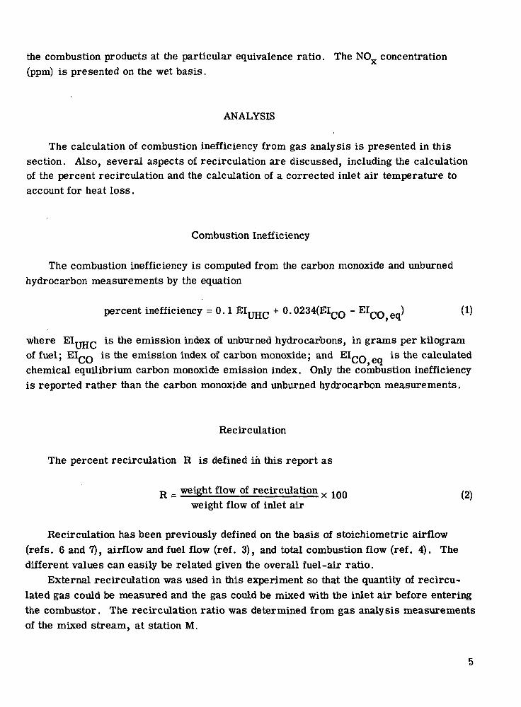
Combustion inefficiency . - The combustion efficiency was improved as the percentrecirculation was increased, as shown in figure 5. At the higher equivalence ratios theefficiency was significantly improved. The equivalence ratio range for good combustionefficiency nearly doubled. With a recirculation of 10 percent, equivalence ratios from0.38 to 0.64 could be prescribed while maintaining combustion efficiencies of 99.5 per-
8

cent or higher. When the recir'culation was increased to 25 percent or higher, the rangeof equivalence ratios for operation with efficiencies of 99.5 or higher was increased tobetween 0.38 and 0.85, a range almost double that for 10-percent recirculation. Increas-ing the percent recirculation preheated the inlet air mixture to improve fuel vaporizationand increased the mixing intensity in the combustor. The instrumentation limited theminimum combustion inefficiency to 0.01 percent, as shown in figure 5, although some ofthese points may represent even lower inefficiencies.
Almost all of the improvement in combustion inefficiency was achieved by increasingthe recirculation ratio from 10 to 25 percent, an effect similar to the NO emission re-
Ji
suits in figure 4.
Effect of Recirculation at Varying Inlet Temperature
The system was operated at three inlet air temperatures which would correspond tovarious values of flame temperature at a given equivalence ratio and simulate variousamounts of heat removal.
Oxides of nitrogen. - Figure 6 presents the NO emission index data for 10- and 50-««^_^_^_««««^^_^ai »w»__«*av J^
percent recirculation. For an inlet temperature increase of 200 K (from 590 to 790 K)the NOV would be expected to be three to four times greater (ref. 11). The maximum in-
2icrease for 10-percent recirculation and an equivalence ratio of 0. 55 was 0.54 timesgreater for the 200 K inlet temperature increase (fig. 6(a)). For 50-percent recirculation(fig, 6(b)), the maximum increase was 0.6 times greater for the same equivalence ratio.One probable explanation for this reduced temperature sensitivity is that heat lossesalso increased with the inlet temperature increase, and the effective flame temperaturechange was relatively small.
Combustion inefficiency. - The combustion inefficiency was reduced with increasingtemperature for 10-percent recirculation (fig. 7(a)). For 50-percent recirculation(fig. 7(b)), the combustion inefficiency changed slightly with temperature. The decreasein combustion inefficiency with increased temperature was small compared with thechange with increased recirculation (fig. 5).
Correction for heat losses. - Although in this experiment a minimum amount ofcooling was desired, some cooling was necessary to prevent burnout of the combustorand recirculation loop. The cooling loss varied from 5 to 20 percent of the heat of com-bustion depending on the equivalence ratio, the percent recirculation, and the referencevelocity. Figure 8 shows the measured recirculation mixture temperature TM and thecorrected inlet air temperature TL, calculated for adiabatic recirculation with the samemixture and flame temperatures (see ANALYSIS section, eq. (6)). The NO data of fig-ure 4 are replotted in terms of concentration (ppm) as a function of equilibrium flametemperature Tj. (based on Tk and metered fuel-air ratio) in figure 9. Correcting the

data for heat losses showed that the variation of NO with flame temperature was simi-A.
lar at the three levels of recirculation. The peak NCL. values were all near 170 ppm.A
The effect of recirculation as a diluent in reducing the oxygen atom concentrationand hence the nitrogen oxide level at a given calculated flame temperature appears tohave been present, but the effect was not definitive. At the lower temperatures, say1700 K, there was a reduction in NO with an increase in recirculation from 10 to 25
A,
percent followed by an increase in NOV when the percent recirculation was increasedX
from 25 to 50 percent. At higher temperatures, above 2000 K, the values of the NOX
at 25- and 50-percent recirculation were above those for 10-percent recirculation. Theshift in the peak NO with recirculation was probably due to the changes in fuel distribu-
X
tion at the higher mixture temperatures and higher velocities which occurred with in-creased recirculation. At temperatures below these maximums, the experimentalcurves were approximately parallel to the well-stirred-reactor curves for data below1900 K after the corrections were applied for heat loss.
The peaks in the experimental curves were probably the result of the local fuel-airratio going through an equivalence ratio of 1. The flame temperatures had been calcu-lated at the metered fuel-air ratios by assuming the combustor was homogeneous. Thewell-stirred-reactor predictions are plotted only for lean equivalence ratios. At equiv-alence ratios above stoichiometric the predicted values of NO would decrease.
X
Although oxygen atom dilution and possibly other effects may have been present,cooling was apparently the major effect of recirculation. The data of reference 4 for thelean primary configuration (referred to as configuration B in ref. 4) and the rich primaryconfiguration (referred to as configuration E) are plotted against the calculated equilib-rium flame temperature in figure 10. The combustion products were cooled to the inletair temperature before they were recirculated back to the combustor, which resulted ina lowering of the maximum flame temperature. There was a distinct decrease of NO..
X
with increasing recirculation, principally caused by the lowering of the flame tempera-ture. There were other effects also, particularly for the lean primary combustor. Withincreased recirculation there was a decrease in residence time in the combustor, andwith the higher mass flows, an increase in mixing intensity also affecting combustoremissions. A small effect of oxygen atom dilution may also have been present.
Effect of Recirculation at Varying Reference Velocity
As the percent recirculation was increased, the residence time in the combustor de-creased. The residence time t of the combusting gas was calculated by
(7)
10

where LC was 28 centimeters and LR was 53 centimeters. The residence time in-cludes the recirculation loop because the emissions data are reported for the recircula-tion gas-sampling station R. This station was assumed to be representative of a com-bustor with residence time necessary to result in complete combustion. As statedearlier, the combustion inefficiency at the combustor exit measured with the traversingprobe was always more than 5 percent.
The residence time is inversely proportional to the reference velocity U , and theratio of the flame temperature TF to the inlet air temperature T,. The time decreasedfrom about 65 to 15 milliseconds as the recirculation ratio was increased from 10 to 50percent.
The effect of residence time was investigated by varying the combustor referencevelocity from 10 to 30 meters per second (fig. 11). There was only a small differencein the emission index of NO as the reference velocity was varied from 10 to 30 meters
Ji
per second. The maximum equivalence ratio obtained at 30 meters per second was 0.6because of fuel flow limitations. There was a slight decrease in NO at 30 meters per
Ji
second, but the variation was less than expected. Data at 25- and 50-percent recircula-lation not presented, showed no change in NO with reference velocity. The combustion
A
inefficiency data, not presented, did not vary as the reference velocity was changed.
Emissions Without a Flameholder
Emissions were measured without a flameholder present. After initial ignition,the mixed gas temperature was high enough to maintain combustion. The burner oper-ated stably. Without the flameholder pressure drop, approximately 0. 5 percent of thetotal pressure at the 15-meter-per-second reference velocity, the ejector nozzles pro-duced higher recirculation rates. Supplemental cooling (fig. 2) was added to the mixingleg of the rig. Figure 12 shows good agreement of NO levels with and without the
A.
flameholder at 50-percent recirculation. Even though the gas in the recir.culation zonebehind the flameholder had a much longer residence time, which produced higher NOX
values, the overall mean residence time was the same with and without the flameholderat the same reference velocity and percent recirculation. With 80-percent recirculationthe NO level was about half the value for 50-percent recirculation at lean equivalence
A
ratios. Removal of the supplemental cooling resulted in some increase in the NOalevels.
The combustion inefficiency is shown in figure 13 without the flameholder present.The range of equivalence ratios for efficient operation was narrow compared with thatfor operation with the flameholder present. This was attributed to the decrease in mix-ing intensity and the absence of the hot internal recirculation zone behind the flame-holder.
11
All other data presented were taken with the flameholder in place without supple-mental cooling.
Effect of Quenching Air Jets on Oxides of Nitrogen
The air ejector can be considered a quenching jet for the recirculating combustiongases. If quenching is rapid, no nitrogen oxides will be produced. If the quenching isslow, the addition of the air (an oxygen-rich stream) can produce more nitrogen oxideswhen the combustion gases are at temperatures above 2000 K.
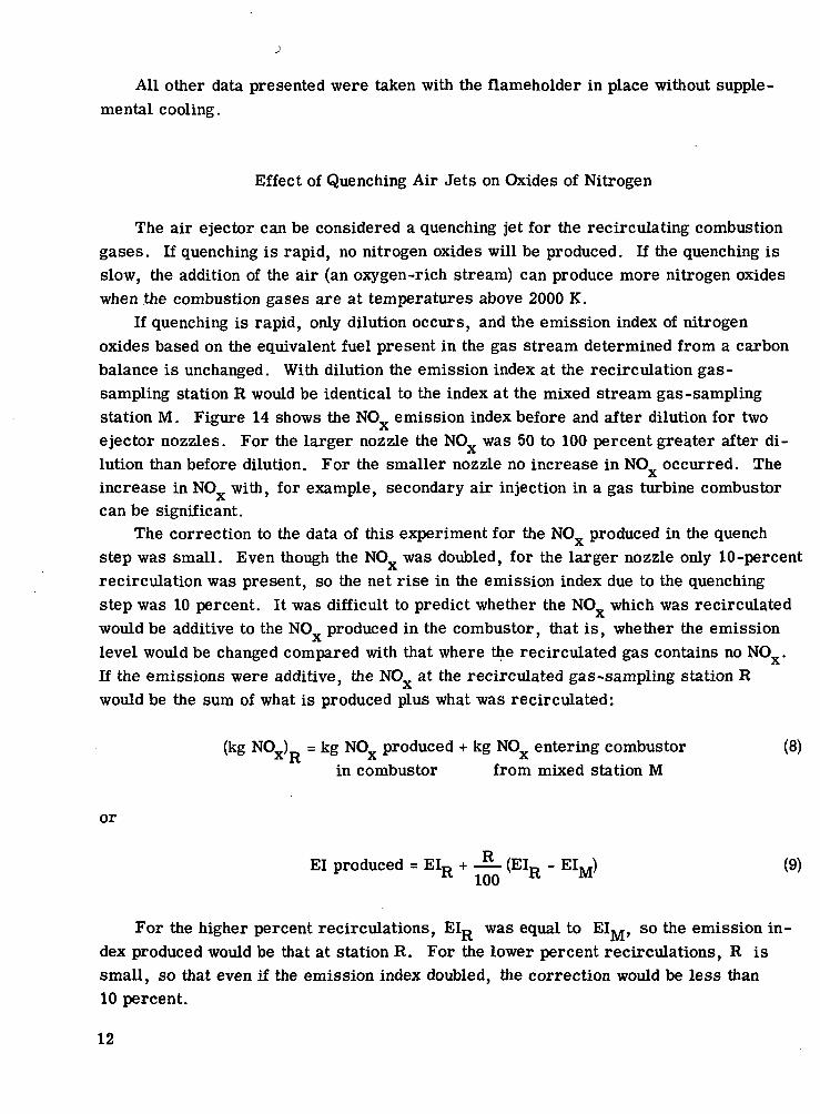
If quenching is rapid, only dilution occurs, and the emission index of nitrogenoxides based on the equivalent fuel present in the gas stream determined from a carbonbalance is unchanged. With dilution the emission index at the recirculation gas-sampling station R would be identical to the index at the mixed stream gas-samplingstation M. Figure 14 shows the NO emission index before and after dilution for two
J±
ejector nozzles. For the larger nozzle the NO_ was 50 to 100 percent greater after di-X
lution than before dilution. For the smaller nozzle no increase in NOV occurred. TheX
increase in NOV with, for example, secondary air injection in a gas turbine combustorX
can be significant.The correction to the data of this experiment for the NO produced in the quench
X\
step was small. Even though the NOV was doubled, for the larger nozzle only 10-percentji
recirculation was present, so the net rise in the emission index due to the quenchingstep was 10 percent. It was difficult to predict whether the NO_ which was recirculated
X
would be additive to the NOV produced in the combustor that is, whether the emissionX
level would be changed compared with that where the recirculated gas contains no NO .A
If the emissions were additive, the NO., at the recirculated gas-sampling station R.X
would be the sum of what is produced plus what was recirculated:
(kg NOJ_ = kg NO... produced + kg NO entering combustor (8)H ¥•? H A
in combustor from mixed station M
or
El produced = £!„+-£_ (EIB - EL.) (9)n 100 K M
For the higher percent recirculations, EL, was equal to EIM, so the emission in-dex produced would be that at station R. For the lower percent recirculations, R issmall, so that even if the emission index doubled, the correction would be less than10 percent.
12

SUMMARY OF RESULTS
The effects of nearly adiabatic recirculation of an inert diluent on combustor emis-sions were investigated. Emission levels of nitrogen oxides (NO ), carbon monoxide,
X
and unburned hydrocarbons were measured for recirculation rates of 10 to 80 percentof the inlet airflow. The unburned hydrocarbon and carbon monoxide emissions werereported as combustion inefficiency. Liquid Jet A fuel was used. The combustor pres-sure was maintained constant at 0.5 megapascal. The equivalence ratio was variedfrom 0.3 to 1.0, the inlet air temperature from 590 to 800 K, and the combustor refer-ence velocity from 10 to 30 meters per second. Data were obtained with and without aflameholder present.
When the exhaust gas was recirculated, the oxygen concentration was decreased,the residence time in the combustor decreased, the mixing intensity increased, and thefuel vaporization rate increased.
Increasing the recirculation from 10 to 25 percent showed a significant reduction inemissions, but further increases from 25 to 50 percent had little effect. The increasein recirculation from 10 to 25 percent resulted in at least a 40-percent reduction in NCL.
X
emission index for equivalence ratios less than 0.63 and reduced the peak value by37 percent. Above an equivalence ratio of 0.7, the recirculating exhaust products in-creased the NO emission index. The combustion efficiency was increased as the per-
A.
cent recirculation increased, particularly at the higher equivalence ratios. The equiva-lence ratio range nearly doubled for combustion efficiencies greater than 99. 5 percent.
The flame-tube combustor with recirculation showed a reduced dependence of inletair temperature on NO emissions as compared with a well-stirred-reactor program.aA 200 K rise in inlet air temperature increased the NO., emission index by 60 percent
X
rather than the predicted 300 to 400 percent, principally as a result of increased heatloss with increased inlet temperature.
Recirculation reduced the dependence of residence time on NO., emissions. Aathreefold decrease in combustor reference velocity changed the NO_ emission index
X
insignificantly.The flame-tube combustor with recirculation could operate stably without a flame-
holder; NO emissions were comparable to those in flameholder runs, but combustionX.
inefficiency increased without a flameholder.The cooling by heat loss appeared to be the major reason for the reduction in NOYX
emissions by recirculation. Nonthermal effects such as increased mixing intensity,reduced residence time, and oxygen atom concentration reduction appeared to be pres-ent, but their role could not be quantitatively defined.
Equating the air ejector to a quench jet showed that inadequate quench rates could
13

produce significant increases in nitrogen oxides by reaction of the exhaust gases withthe inlet air.
Lewis Research Center,National Aeronautics and Space Administration,
Cleveland, Ohio, July 2, 1976,505-03.
REFERENCES
1. Ingebo, Robert D.; and Norgren, CarlT.: Effect of Primary-Zone Water Injectionon Pollutants From a Combustor Burning Liquid ASTM A-l and Vaporized PropaneFuels. NASA TN D-7293, 1973.
2. Marchionna, Nicholas R.; Diehl, Larry A.; and Trout, Arthur M.: Effect of WaterInjection on Nitric Oxide Emissions of a Gas Turbine Combustor Burning NaturalGas Fuel. NASA TM X-2959, 1973.
3. Breen, B. P.: Operational Control of the Nitric Oxide Emissions From StationaryBoilers. Proceedings of the Fifteenth Symposium on Emissions From ContinuousCombustion Systems, Walter Cornelius and William G. Agnew, eds., PlenumPress, 1972, pp. 325-344.
4. Hazard, H. R.: Reduction of NO by EGR in a Compact Combustor. J. Eng. forA
Power, ASME Trans., vol. 96, no. 3, July 1974, pp. 235-239.
5. Pompei, Francesco; and Gerstmann, Joseph: NO Production and Control in Pre-A
mixed Gasoline-Fired Combustion System. Am. Inst. Chem. Eng. Symp., ser.148, vol. 71, 1975, pp. 120-126.
6. Cooper, P. W.; et al.: Recirculation and Fuel-Air Mixing as Related to Oil BurnerDesign. API-M23, Am. Petroleum Inst., 1964.
7. Cooper, P. W.; and Marek, C. J.: Design of Blue-Flame Oil Burners UtilizingVortex Flow or Attached-Jet Entrainment. API-1723-A, Am. Petroleum Inst.,1965.
8. Homer, J. B.; and Button, M. M.: Nitric Oxide Formation and Radical Overshootin Premixed Hydrogen Flames. Combustion and Flame, vol. 20, no. 1, Feb. 1973,pp. 71-76.
9. Boccio, J. L.; Weilerstein, G.; and Edelman, R. B.: A Mathematical Model forJet Engine Combustor Pollutant Emissions. (GASL-TR-781, General Applied Sci.Labs., Inc., NASw-2235.) NASA CR-121208, 1973.
14

10. Marek, Cecil J.; and Papathakos, Leonidas C.: Exhaust Emissions From a Pre-mixing, Prevaporizing Flame Tube Using Liquid Jet A Fuel. NASA TM X-3383,1976.
11. Lipfert, F. W.: Correlation of Gas Turbine Emission Data. ASME Paper72-GT-60, Mar. 1972.
15

Inletair
Inlet air t^ejector •—nozzle—""
Recirculationgas-samplingprobe,station R —
- Traversinggas-samplingprobe, station C
All piecesstandard 10.2-cm (4-in.)schedule 40 pipe,type 304 stainless steel—-
Combustorpressure ___„=tap—"""'
-63.5 cm-
Exhaust tot water quench1 and back pressure
valve
„--- Combustor
--120°, 5.9-cm-diamcone flamestabilizer
'-Jet Afuel
-Mixed gas-sampling probe,(f/a)M, station M
Figure 1. - Sketch of recirculation test rig.
Figure 2. - Overall view of recirculation rig showing instrumentation and supplemental coolingwater bath.
16

Q. E CM—.^__
IO< D I
I _L
•I 8^2 "»
.
ox||
•Sfe
g 3* fcI §S1
'.f s** re £
£5 fe
'xapui uo)ss|Ui3 XQN
o(D '•?c roegg S»R
*ia
°4E SSS^ | « rr! exi cvl
id =5U7
0< D
O
S
is
.2 £ £
sI te
: f_.
R ' S3'
17

t- ?8. Z
I .81 '6
| .4.2t/»3 9£» •£
.08
.06
.M
.02
.01
Nominalrecirculation,
percent -
.2 .4 .6 .8Equivalence ratio
1.0 1.2
Figure 5. - Effect of recirculation rate on combustion in-efficiency. Inlet air temperature, 590 K; pressure,0.5 megapascal; reference velocity, 15 meters per sec-ond.
18

12r
lO-
.2
.2 .4 .6 .8 1.0 1.2 .2Equivalence ratio
.4
Inlet airtemperature,
KO 590A 700 -D 790O 800
.6 .8 1.0 1.2
(a) Nominal recirculation, lOpercent. (b) Nominal recirculation, 50percent.
Figure 6. - Effect of inlet air temperature on NOX emission index. Pressure, 0.5 megapascal; reference velocity,15 meters per second.
19

40
20
1086
^ Jo .0'«J ,*= .6<Dc
.2
.2
.1.08
.06
.04
.02
.01.2 .4 .6
Inlet airtemperature,
K
1.0 1.2 .2 .4Equivalence ratio
.6 1.0 1.2
(a) Nominal recirculation, 10 percent. (b) Nominal recirculation, 50 percent.
Figure?. - Effect of inlet air temperature on combustion inefficiency. Pressure, 0.5 megapascal; reference velocity,15 meters per second.
20

ludd • XON
a>
C -o £ -a '" _S 0£0 ^t±!^5f e r t C " K o | o c ^
^ x &-G I•o = c <» "
0<D =5 g. " ~
1_ *"™ £ fe
•- ||
si J!
2 " _: a,o> B S oo ro _ c
> c JK 5 p>• i S. ~ feg § 3 ff
o- -a 8"-a'uj w = ro
3 ro g
S3-S 15 o
CSJ O• o> 2
"S-2 5£ 2 SZJ OJ i-
5? R
21

100
80
Ic 60
40
20
Nominalrecirculation,
percent
01015-1620-22
1300 1500 1700 1900 2100 1300 1500 1700Primary zone equilibrium flame temperature, TF, K
1900 2100
(a) Configuration B, lean primary zone. (b) Configuration E, rich primary zone.
Figure 10. - Concentration of NOX emissions as function of primary zone equilibrium flame tem-perature (ref. 4). Recirculated products cooled to inlet air temperature of 310 K; combustorpressure, 0.1 megapascal; reference velocity, 1.5 to 3.0 meters per second.
.2 .4 .6 .8Equivalence ratio
Figure 11. - Effect of reference velocity on NOX emissionindex. Inlet air temperature, 590 K; pressure,0.5 megapascal; nominal recirculation, lOpercent.
22

'c
IIS E
era's0I i*
> „•. o> ^ I_ CD
1 li^
. f l\ .t QJm >
suonsnquioo
?! E-8
£ 8
« CM .
O10 '*3 '
= J2<u o>•a -a Q
I o O w> W»,«« 11
E E
_L I
.ip« .5-1
I 1*1.> TO CD O
S- fe« S
« S 3= £ S0.0.0.
« »»
|8nj B)|/ZON 6
23

20
16
12
4
OA
Nozzlediameter,
cm3.202.03
Open symbols denote inlet air temperature of 590 KSolid symbols denote inlet air temperature of 800 K
doubled Rapidquench
0 4 8 12 16 20NOX emission index before dilution, EIR, g N02/kg fuel -
Figure 14. - Production of NOX by quenching jet (ejector). Pres-sure, 0.5 megapascal; reference velocity, 15 meters per second.
24 NASA-Langley, 1976 E-8803

NATIONAL AERONAUTICS AND SPACE ADMINISTRATION
WASHINGTON. D.C. 2OS46 POSTAGE AND FEES PAIDNATIONAL AERONAUTICS AND
OFFICIAL BUSINESS
PENALTY FOR PRIVATE USE S3OO SPECIAL FOURTH-CLASS RATEBOOK
POSTMASTER : If Undeliverable (Section 158Postal Manual) Do Not Return
"The aeronautical and space activities of the United States shall beconducted so as to contribute . . . to the expansion of human knowl-edge of phenomena in the atmosphere and space, The Administrationshall provide for the widest practicable and appropriate disseminationof information concerning its activities and the results thereof."
—NATIONAL AERONAUTICS AND SPACE ACT OF 1958
NASA SCIENTIFIC AND TECHNICAL PUBLICATIONSTECHNICAL REPORTS: Scientific andtechnical information considered important,complete, and a lasting contribution to existingknowledge.
TECHNICAL NOTES: Information less broadin scope but nevertheless of importance as acontribution to existing knowledge.
TECHNICAL MEMORANDUMS:Information receiving limited distributionbecause of prelm.inarv data, security classifica-tion, or other reasons. Also includes conferenceproceedings with either limited or unlimiteddistribution.
CONTRACTOR REPORTS: Scientific andtechnical information generated under a NASAcontract or grant and considered an importantcontribution to existing knowledge.
TECHNICAL TRANSLATIONS: Informationpublished in a foreign language consideredto merit NASA distribution in English.
SPECIAL PUBLICATIONS: Informationderived from or of value to NASA activities.Publications include final reports of majorprojects, monographs, data compilations,handbooks, sourcebooks, and specialbibliographies.
TECHNOLOGY UTILIZATIONPUBLICATIONS: Information on technologyused by NASA that may be of particularinterest in commercial and other non-aerospaceapplications. Publications include Tech Briefs,Technology Utilization Reports andTechnology Surveys.
Details on the availability of these publications may be obtained from:
SCIENTIFIC AND TECHNICAL INFORMATION OFFICE
N A T I O N A L A E R O N A U T I C S A N D S P A C E A D M I N I S T R A T I O N
Washington, D.C. 20546