effect of multiwalled carbon nanotubes on co-mn …the synthesis process of mwcnts/ferrites started...
TRANSCRIPT

Digest Journal of Nanomaterials and Biostructures Vol. 11, No. 1, January - March 2016, p. 149 - 157
EFFECT OF MULTIWALLED CARBON NANOTUBES ON Co-Mn FERRITE
PREPARED BY CO-PRECIPITATION TECHNIQUE
A. HAKEEMa, G. MURTAZA
b,,c*, I. AHMAD
b, P. MAO
c, X. GUOHUA
c,
M. T. FARIDb, M. KANWAL
b, G. MUSTAFA
b, M. HUSSAIN
c, M. AHMAD
d
aDepartment of Physics, Govt. Post Graduate College Jampur, Pakistan
bDepartment of Physics, Bahauddin Zakariya University, Multan 60800 Pakistan
cDepartment of Polymer Science and Engineering, Zhejiang University, Hangzhou
310037 PR China dDepartment of Physics, COMSATS Institute of Information Technology, Lahore
54000, Pakistan
Multiwalled carbon nanotubes (MWCNTs) are substituted in the soft ferrite
Co0.5Mn0.5Fe2O4, with weight percent ratio of 1%, 5% and 9%. The effect of MWCNTs on
the Structural, Thermal and Magnetic properties of Co-Mn ferrites is reported. The X-ray
diffraction analysis reveals the ferrite posses spinel cubic structure. Structural, Thermal
analysis of the MWCNTs and Co-Mn ferrite composite are characterized by XRD, SEM
and TGA/DSC techniques. The sintered powder at 1000°C under atmospheric environment
shows spinel cubic structure. Particle size is observed by SEM ranging from 20 nm to
35nm. The magnetic properties are measured by using the Physical property measurements
(PPMS) technique. The Fourier transform infrared spectroscopy detects the presence of the
metallic compounds in the ferrite sample.
(Received December 9, 2015; Accepted February 8, 2016)
Keywords: X-ray scattering; differential scanning calorimetry (DSC); Fourier transform
infrared spectroscopy (FTIR); Thermo gravimetric analysis (TGA).
1. Introduction
The third allotrope was carbon nanotubes (CNTs), next to diamond and graphite which
were discovered in 1991[1].These possesses remarkable properties such as extremely high tensile
strengths (150-180GPa), ballistic thermal conduction (>300 w/mK for individual tubes), electric
modulus (640Gpa to 1Tpa) and high electrical conductivity [2-5] have been unveiled. To make
high frequency transformers, chokes, inductor coils, cores of audio frequency, magneto optical
displays, microwave absorbers, permanent magnets, gas sensors and wave guides in GHz range
were mostly prepared by ferrites [6, 7]. The synthesis process of MWCNTs/Ferrites started later as
compared to MWCNTs/Polymer composites but it is not developed yet. The MWCNTs/Ferrite
composites were prepared by a solid state reaction method. The well known magnetic compounds
are ferrites that have been studied for the potential application in magnetic recording media and in
microwave absorber devices due to their novel physical properties [8-11]. In the recent years
studies on the properties of Nano sized ferrite particles have drawn considerable interest because
of their fundamental importance in understanding the physical processes and their applications for
many technological purposes. Cobalt ferrites have emerged as one of the important ferromagnetic
materials because of their low eddy current losses and high electrical resistivity. These have cubic
spinel structure and are being extensively studied on the basis of their interesting magnetic and
electrical properties. The structural stability of the Nano sized particles of cobalt ferrite plays an
important role in technical applications. The chemical method of preparation has a great impact on
the physical and structural properties of the Nano sized constituents. The well chemical
*Corresponding author: [email protected]
150
homogeneity in the Nano sized particles can be achieved by mixing them at the molecular level.
The synthesis of Nano sized particle has a major impact on the shape and size distribution. The
chemical routes of Nano sized particle preparation have emerged as a popular tool of synthesis for
spinel ferrites. Nano sized particles can be obtained by using the various preparation methods.
Among these the well known method of preparations of Nano sized particles are hydrothermal
synthesis [12-15], co-precipitation [16-20], sol-gel [21-24], spray drying [25], solid state micro
emulsion processes [26-28] and mechanical alloying [29-32]. Spinel ferrites have a numerous
applications in different fields like Ferro fluids, magnetic recording, magnetic resonance imaging
(MRI) and hot gas desulphurization etc. [33-36]. Spinel ferrites have the structural formula M
Fe2O4where M is divalent metal ion from the 3d transition elements like Cu, Ni, Zn, Co, Mn etc,
and a unit cell has 32 oxygen atoms in a cubic closest packing while octahedral and tetrahedral
sites are available for cations [37, 38]. Normally in a spinel structure, divalent M2+
cation enter at
the tetrahedral sites, and Fe3+
ions occupy the octahedral sites. Intermediate configurations are
generally temperature dependent and are commonly defined by the inversion coefficient [38]. Co-
precipitation method is chosen in the present work for preparing Co-Mn ferrites. As it is easy and
convenient method to produce homogeneous Nano ferrites. It is well known fact that the ferrites
intrinsic properties largely depend on the method of preparation, chemical composition and cation
distribution. Crystalline structure of the composite Nano particles is characterized by XRD and
scanning electron microscope (SEM). The FT-IR spectrum of the ferrite sample is recorded to
make sure of the presence of the metallic compounds.
2. Experimental method and calculations
2.1 Materials
All the chemical re agents Co(NO3)2.6H2O, Mn(NO3)2.6H2O and Ferric nitrate Nona
hydrate Fe(No3)3.9H2O of Sigma Aldrich, Multiwalled carbon nanotubes (MWCNTs) were
purchased from Shenzhen Nanotech Port Co. Ltd., and hydrochloric acid HCl, Nitric acid HNO3
were of Merck co. Germany. These acids are used to purify the MWCNTs. The length and
diameter of the MWCNTs were 20m and 20nm, respectively.
2.2 Synthesis method
Nano crystalline Cobalt ferrites Co0.5Mn0.5Fe2O4 were prepared by co-precipitation
method. The desired composition was obtained by taking stoichiometric amount of
Co(NO3)2.6H2O, Mn(NO3)2.6H2O and Fe(NO3)3.9H2O were dissolved in deionized water.
Ammonia solution was used to make the precipitate. The pH value of the solution becomes 10 and
it was stirred for at least 2hrs so that the solution becomes neutral. Put the solution in a sonicater
for 20 minutes then place it in the ultrasonic bath for a while so that precipitate will settle down
then filter it with a filter paper. Wash the precipitate with deionized water until it becomes free of
impurities. The product was dried at 100ºC for 5 hours to remove water contents. The dried
powder was calcinated at 1000ºC and mixed the ferrite with multiwall carbon nanotubes having
weight percentage ratio of 1%, 5% and 9%. Several strategies have already been developed over
the last decade to obtain MWCNTs as a pure as possible, and to minimize the influence of
impurities on the performance of composites. Impurities can indeed affect the batch to batch
reproducibility of the results, and accordingly influence on the properties of the final composite.
The method we have used to purify the MWCNTs is by using the hydrochloric acid (HCl) and
nitric acid (HNO3) with 1:3 by volume as it is reported in the literature [39-41].
2.3 Characterization
The X-ray diffraction (XRD) patterns of the samples were recorded on a BRUKER X-ray
powder diffractometer using CuK (1.54060Å) radiation. The scans of the selected diffraction
peaks were carried out in the step mode. Scherrer’s method can be used to calculate the crystallite
size of the particles [42]. Thermo gravimetric studies (TG) and differential scanning calorimetric
studies (DSC) were done on SDTQ600 V8.2 Build 100, Module DSC-TGA standard, Inst Serial
0600-0109 and the heating rate was kept at 10 °C/min. The infra red (IR) spectrum of ferrite
151
sample was recorded on Shimadzu Model 8201, Fourier Transform infra red (FTIR) in the range
of 4000cm-1
to 450cm-1
were recorded in the presence of KBr medium at room temperature.
Magnetic properties were measured by PPMS ACMS Option Version 1.0.9 Build 14.
2.4 Calculations
The lattice constant ‘a’ was determined by using the following relation:
a = 𝑑ℎ𝑘𝑙√ℎ2 + 𝑘2 + 𝑙2 (1)
where dhkl is the distance between the adjacent Millar planes (h k l). dhkl can be calculated by the
relation:
dhkl = 𝑛
2 sin (2)
with n = 1 for the cubic system,
The X-ray density 𝑥 can be calculated by the help of Smit and Wijin relation [43].
𝑥= 𝑍𝑀
𝑁𝑎3 (3)
Where M is the molecular weight and N is the Avogadro’s number (6.023 x10²³
atoms/mol), Z is
the number of molecules pet unit cell (for oxide compounds with cubic spinel structure Z = 8) and
‘a’ is the lattice parameter in (cm). The average particle size was calculated by using the Scherrer’s
equation
D = 0.9
𝑐𝑜𝑠 (4)
Where D is crystallite size, is the wavelength of the X-ray radiation, is the Bragg’s angle, and
is the line width at maximum height [44]. The porosity can be calculated by the following
relation
P = 𝑥−𝜌𝑚
𝑥
(5)
Where 𝑥 the density is calculated by Eq. (3), and 𝜌𝑚 is the measured density. It can be calculated
by the following relation.
𝜌𝑚 = 𝑀
𝑉 =
𝑀
𝜋𝑟2 𝑡 (6)
Where M is the mass, t is the thickness and r is the radius of the pellet.
The X-ray diffraction of sintered Cobalt-Maganese ferrite sample sintered at 1000ºC is
subject to calculate the average particle size using Debye –Scherrer formula. The crystalline
structures of composite Nano particles are characterized by Scanning Electron Microscope (SEM).
3. Results and discussions
The X-ray diffraction patterns of Co0.5Mn0.5Fe2O4 powders fired at 1000°C. The x-ray
diffraction measurement shows that all peaks of Co0.5Mn0.5Fe2O4 consist with those of a typical
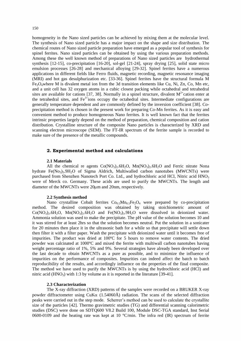
spinel structure of a cobalt ferrite prepared by co-precipitation method. Fig.1 illustrates the XRD
patterns of the ferrite, carbon nanotubes composites having weight percent 1%, 5% and 9%. The
XRD pattern of the ferrite indicates that the material is based on cubic spinel crystal structure of
ferrite. The average crystallite size was in the range of 20-35nm. The strong diffraction peaks at 2
= 18.2, 30.22°, 35.53°, 43.30°, 53.58°, 57.35°, 62.72°, 73.2, 78.6 corresponds to (220), (311),
(222), (400), (422), (511), (440), (533), (444) typical planes of Co-Mn ferrite spinel structures with
face centered cubic phase according to the standard card JCPDS file no. 520278 [45, 46].
152
In the XRD of Multi wall carbon nanotube, the broadened peak at 2 = 26.3º indicates that
the carbon nanotubes are present and no deformation takes place in their structure. In Fig. 1 all the
XRD patterns of the (a) ferrite (b) Multiwall Carbon Nanotubes (MWCNTs) (c) composite which
is formed by mixing the ferrite with 1% weight ratio of multiwall carbon nanotubes (d) composite
which is formed by mixing the ferrite with 5% weight ratio of multiwall carbon nanotubes (e)
composite which is formed by mixing the ferrite with 9% weight ratio of multiwall carbon
nanotubes. The XRD pattern of MWCNTs (JCPGS 01-0640) purified by HCl and HNO3 with
volume ratio 1:3 is shown in Fig. 1(b). The interplanner spacing corresponding to (002) plane is
found to be 3.35Å like pure graphite. XRD patterns shows an increase in the intensity of (002)
plane peak, when we have mixed only 1% of MWCNTs the (002) plane peak is not prominent but
on increasing the further amount of MWCNTs the (002) plane peaks become prominent especially
(100) plane peak and the main peak of the spinel cubic structure reduces in intensity due to the
percentage increase in of multiwalled carbon nanotubes and the reduction of the grain size. It
means that increasing amount of multiwall carbon nanotubes has a great influence on the structural
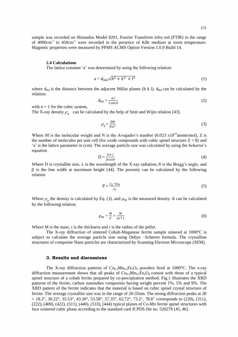
properties of the ferrite. The Scanning Electron Microscope (SEM) images are shown in Fig. 2.
The SEM image of a pure ferrite is shown in Fig. 2(a) and the images of the composites are shown
in Fig. 2(b-d) having percentage of multiwall composite 1%, 5% and 9%, respectively. SEM
images clearly indicate the increasing percentage of multiwalled carbon nanotubes. The SEM
image of a pure multiwall carbon nanotube is shown in Fig. 2(e). The images show that the
multiwall carbon nanotubes having hollow cylindrical structure make agglomerates. All the
obtained results are presented in Table 1.
10 20 30 40 50 60 70 80
(004)
Composite 5%
Ferrite
MWCNT
Composite 1%
Composite 9%
2-Theta (degree)
Rela
tive I
nte
nsit
y (
a.u
)
(a)
(b)
(c)
(d)
(e)
(111)
(220) (311)
(222)
(400)
(422)
(511)
(440)
(002)
(100)
(533)
(444)
Fig. 1 XRD patterns of (a) Ferrite Co0.5Mn0.5Fe2O4, (b) Multiwall carbon nanotubes, (c) Composite with 1%
MWCNTs, (d) Composite with 5% MWCNTs (e) Composite with 9% MWCNTs.
Table 1. The lattice parameter ‘a’, Crystallite Size D(nm), X-ray density(gm/cm3), Actual density(gm/cm
3)
and porosity values of Ferrite and composites are given below.
Sample Parameter Ferrite MWCNTs Comp1% Comp 5% Comp 9%
Lattice Parameter ‘a’ (Å) 8.30 5.20 5.10 5.02
Crystallite Size D (nm) 35 20 30 28 25
X-ray density (gm/cm3) 5.12 3.21 3.00 2.25
Actual density (gm/cm3) 3.15 0.02 1.95 1.05 0.45
Porosity (%) 0.385 0.393 0.65 0.8
153
Fig.2 Scanning Electron Microscope (SEM) Images of (a) Co0.5Mn0.5Fe2O4,(b) Co0.5Mn0.5Fe2O4
MWCNTs 1% (c) Co0.5Mn0.5Fe2O4 MWCNTs 5%. (d) Co0.5Mn0.5Fe2O4 MWCNTs 9%,
(e) MWCNTs.
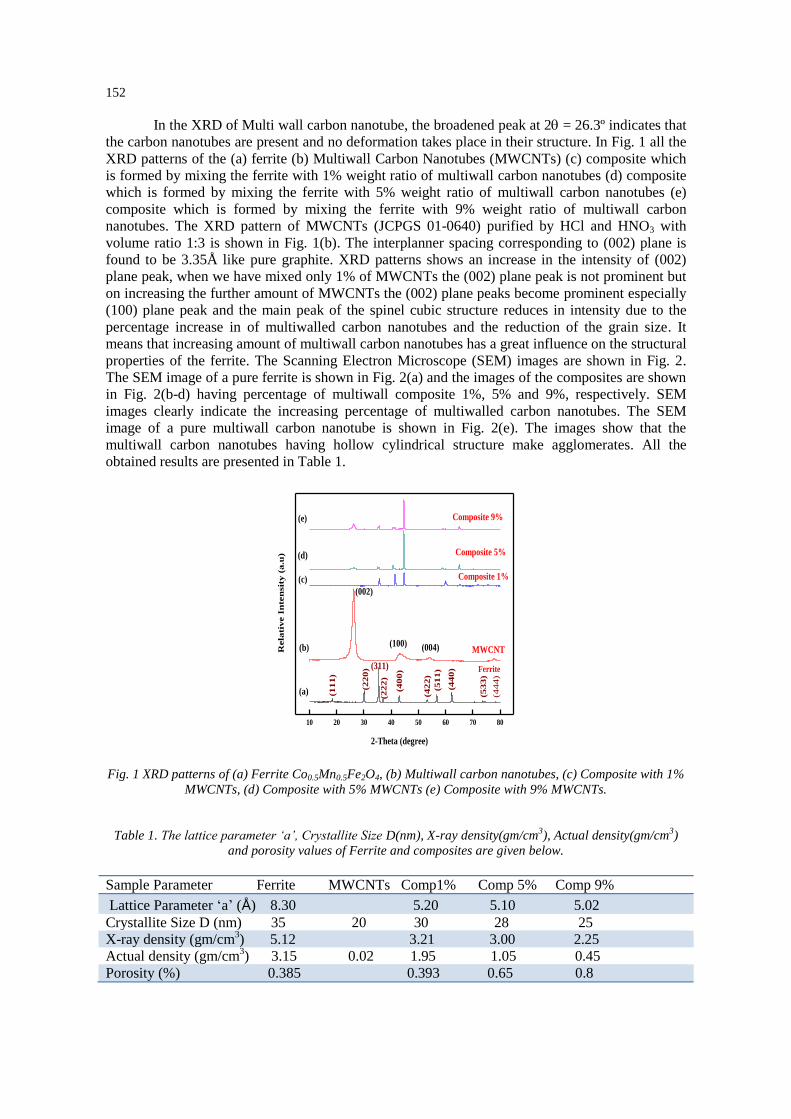
Thermo gravimetric studies (TG) and differential scanning calorimetric studies (DSC)
were done on SDTQ600 V8.2 Build 100, Module DSC-TGA standard, Inst Serial 0600-0109 and
the heating rate was kept at 10 °C/min. TGA-graphs of the samples show maximum weight loss in
the range of 500°C to 600°C. This may be due to dehydration/removal of OH ions and some
organic residues left in the sample. DSC curve of the sample show exothermic peak at 636°C
626°C, 627°C and 628°C, respectively. It may be due to the removal of the hydrocarbon residuals.
TG-DSC curves of the samples show the formation of crystalline phase in the temperature range
600 and above. The pure multiwall carbon nanotubes loss their weight after attaining a temperature
of 500°C, the weight loss is 98.16 % which means that the material remains stable until 500°C
temperature after it abruptly loss in weight takes place as it is depicted in Fig. 3(a).
The composite based on 1% carbon nanotubes gains 6.2% weight. The sample gains
weight after 300°C and this process continues till 575°C and it again losses its weight after
626.26°C and the loss in weight is 3.8% and it again gains weight due to the presence of metallic
ions that is shown in Fig. 3(b).
The composite based on 5% multiwall carbon nanotubes gains weight after 375°C up till a
temperature of 550ºC. The increase in weight is 5.3% then it start to decrease till 650°C, the loss in
weight is 23.1 % and it attains a stable position which is depicted in Fig. 3(c).
The composite based on 9% multiwall carbon nanotubes gains weight after 250°C and it
gains a weight of 2.50% till 580°C then it again losses its weight of 43.3% till 650°C and later on

154
the weight increases abruptly. It’s mean that loss in weight takes place after the addition of
MWCNTs as it is depicted in Fig. 3(d). Multiwalled carbon nanotubes gain weight by the addition
of ferrite particles.
0 100 200 300 400 500 600 700 800
0
2
4
6
8
10
12
Weight Loss Curve
Temperature Difference Curve
Taken Weight 10.749mg
Temperature (C)
Wei
gh
t L
oss
635.62C
98.15%
(a)
-2
0
2
4
6
8
10
12
14
16
18
20
22
24
26
Tem
per
atu
re D
iffe
ren
ce (C
/mg)
0 100 200 300 400 500 600 700 800 900
11.8
11.9
12.0
12.1
12.2
12.3
12.4
12.5
12.6
12.7
Weight Loss
Temperature Difference
Taken Weight 11.866mg
Tem
per
atu
re D
iffe
ren
ce (C
/mg)
626.26C
502.69 C
(b)
Gain
Wt.
6.2
20%
Wt. Loss 3.826%
-2
0
2
Temperature (C)
Wei
gh
t L
oss
0 100 200 300 400 500 600 700 800 9009
10
11
12
13
Weight Loss
Temperatore Difference
Taken Weight 11.613mg
Temperature (C)
Wei
gh
t L
oss
(C)
(626.58 C)
Wt. Loss 23.1%
-2
0
2
4
6
8
10
Tem
per
atu
re D
iffe
ren
ce (C
/mg)
Gain Wt. 5.257%
0 100 200 300 400 500 600 700 800 9005
6
7
8
9
10
11
12
Weight Loss
Temperature Difference
Taken Weight 10.653mg
Temperature (C)
Wei
gh
t L
oss
(d)
(628.36C)
Gain Wt. 2.562%
Loss Wt. 43.34%
-4
-2
0
2
4
6
8
10
12
14
16
18
20
22
Tem
per
atu
re D
iffe
ren
ce (C
/mg)
Fig. 3 Thermo gravimetric (TG) and differential scanning calorimetric studies (DSC) (a) MWCNT, (b)
Co0.5Mn0.5Fe2O4, MWCNT 1% (c) Co0.5Mn0.5Fe2O4, MWCNT 5% (d) Co0.5Mn0.5Fe2O4, MWCNT 9%
500 1000 1500 2000 2500 3000 3500 40000.2
0.3
0.4
0.5
0.6
0.7
Co0.5
Mn0.5
Fe2O
4
Wave number (cm-1)
Tra
nsm
itta
nce
(%
)
(137
3)
(162
4)
(236
3)
(3418)
(525)
Fig. 4 FT-IR spectrum of Co0.5Mn0.5Fe2O4
FTIR spectroscopy is a very useful technique to deduce the structural investigation and
redistribution of cations between octahedral and tetrahedral sites of the spinel structure in
Co0.5Mn0.5Fe2O4 nanoparticles. The band around 1373 cm-1
is for C-H out of plane deformation

155
vibration. The adsorbed water is featured by bands at 3418 cm-1
. The bands at 2363 cm-1
, 1624 cm-
1 are assigned to the O-H stretching and H-O-H bonding modes of vibration, respectively. The
presence of band 525 cm-1
is attributed to the stretching vibration of tetrahedral and octahedral
groups [47-49]. The sketch of the Fourier transform infrared spectroscopy is shown in Fig. 4.
-8000 -6000 -4000 -2000 0 2000 4000 6000 8000-10
-8
-6
-4
-2
0
2
4
6
8
10
-1000 -800 -600 -400 -200 0 200 400 600 800 1000-3
-2
-1
0
1
2
3
Magnetic Field (Oe)
M-D
C (
em
u/g
)
M-D
C(e
mu
/g)
Magnetic Field (Oe)
Co0.5
Mn0.5
Fe2O
4
Co0.5
Mn0.5
Fe2O
4, MWCNTs 1%
Co0.5
Mn0.5
Fe2O
4, MWCNTs 5%
Co0.5
Mn0.5
Fe2O
4, MWCNTs 9%
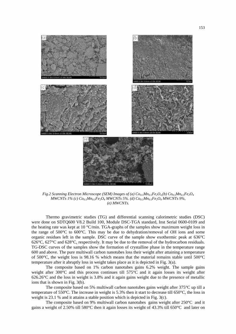
Fig.5 M-H curves for Co0.5Mn0.5Fe2O4 and multiwall carbon nanotubes composites.
The specific M-H curve for ferrite multiwall carbon nanotube composite obtained from
physical property measurements (PPMs) technique is shown in Fig. 5. The sample exhibit linear
magnetization with small coercivety indicating that ferrite nanoparticles are super paramagnetic
the magnetic domains are based on randomly oriented non-interacting particles. The samples
cannot fully saturate at 8KOe, this thing indicate the presence of super paramagnetic and single
domain particles [47, 48].The values of saturation magnetization increased from 2.26 emu/g to
9.35emu/g with the increased percentage quantity of multiwall carbon nanotubes it may be due to
the decoupling effect. The coercivety value for the Nano composite increases from 48 Oe to 152
Oe, showing increased in magnetization results from very well interaction between Nano
crystalline Co0.5Mn0.5Fe2O4 and multiwall carbon nanotube.
4. Conclusions
Samples of Nano crystalline Co0.5Mn0.5Fe2O4 has been successfully synthesized using co-
precipitation method and the effect of multiwall carbon nanotube composite have been studied.
Lattice parameter, density and crystallite size decreases with the increase of MWCNTs
concentration. Porosity increases with the increase of MWCNTs concentrations. DSC curves show
the exothermic peaks at 636C, 626 C, 627 C, and 628 C due to the removal of hydrocarbon
residues. XRD pattern indicates the ferrite is single phase with Face centered cubic structure. The
saturation magnetization increases from 2.26emu/g to 9.35emu/g with the increase of multiwall
carbon nanotubes due to the decoupling effect. The coercivity value increases from 48Oe to
152Oe. The thermal stability and loss in weight of the material increase with the addition amount
of MWCNTs. The crystallite size range was 20nm to 35nm. Materials exhibit the super
paramagnetic behavior as reported by Subhash B. Kondawar et al and G. Murtaza et al [50, 51].
Ferrite and MWCNTs composites are suitable for the application of electromagnetic devices,
biomedical fields such as clinical diagnosis and electrochemical bio sensing. The presence of band
525cm-1
is attributed to the stretching vibration of tetrahedral and octahedral groups

156
Acknowledgement
Corresponding author (Ghulam Murtaza) is thankful to Higher Education Commission
(HEC) of Pakistan for providing financial assistance through IRSIP scholarship and the Zhejiang
University of China for providing opportunity to do work in Carbon Black Polymer Composite
Lab (CBPCL).
References
[1] S. Iijima., Nature 354, 56 (1991).
[2] W. A. De Heer, MRS Bulletin, 29(4), 281 (2004).
[3] J. –P. Salvetat, G. Andrew, D. Briggs, J.-M. Bonard, R. R. Bacsa, A. J. Kulik, T. Stöckli,
N. A. Burnham,L.Forró, Phys. Rev. Lett. 82(5), 944 (1999).
[4] S. Berber, Y. –K. Kwon, D. Tomànek, Phys. Rev. Lett. 84(20), 4613 (2000).
[5] T. W. Ebbesen, H. J. Lezec, H. Hiura, J. W. Bennett.H. F. Ghaemi, T. Thio, Nature,
382(6586), 54 (1996).
[6] K. C. Han, H. D. Choi, T. J. Moon, W. S. Kim, J. Mater. Sci.30, 3567 (1995).
[7] M. R. Meshram, N. K. Agrawal, B. Sinha, P. S. Misra, Bull. Mater. Sci. 25, 169 (2002).
[8] J. L. Dornan, D. Fiorani ,Magnetic Properties of Fine Particles (North-Holland,
London, 1992).
[9] V. Blaskov, V. Petkov, V. Rusanov, L. M. Martinez, B. Martinez, J. S. Munoz and M.
Mikhov, J. Magn. Magn. Mater.162, 331 (1996),.
[10] K. S. Baek, H. N. Ok, J. C. Sur, Phys. Rev. B 39, 2800 (1989).
[11] S. N. Okuno, S. Hashimoto, K. Inomata, J. Appl. Phys. 71, 5926 (1992).
[12] T. Pannaparayil., R. Marande, , S. Komarneni., J. Appl. Phys. 69, 5349 (1991).
[13] M. Rozman., M. Drofenik., J. Am. Ceram. Soc 78, 2449 (1995).
[14] S. Komarneni., E. Fregeau, E. Breval., R. Roy, J. Am. Ceram. Soc. 71, c-26- (1998).
[15] M. Sisk., I. Kilbride, A. J. barker, J. Mater. Sci. Lett 14, 153 (1995).
[16] M. Kiyama. Bull. Chem. Soc. Jpn. 51, 134 (1978).
[17] T. Katsura, Y. Tamura., G.S. Chyo, Bull.Chem. Soc, Jpn.52, 96 (1979).
[18] K. Kaneko., T. Kastura., Bull. Chem. Soc. Jpn. 52, 1080 (1979).
[19] K. Kaneko, K. Takei., Y. Tamura, T. Kanzaki, T. Kastura, Bull. Chem. Soc. Jpn.
52, 1080 (1979).
[20] Y. Tamura, U. Rasyid, T. Kastura, J. Chem. Soc., Dalton Trans, 53, 2125 (1980).
[21] J. G. Lee, J. Y. Park, C. S. Kim. J. Mater. Sci. 33, 3965 (1998).
[22] S. G. Christoskova, M. Stoyanova, M. Georgieva, Appl. Catal. A 208, 235 (2001).
[23] C. O. Arean, M. P. Mentruit, E. E. Platero, F.X.L.I . Xamena., J. B. Parra, Mater. Lett.
39, 22 (1999).
[24] C.S. Kim, Y.S. Yi., K.T. Park., H. Namgung, J. G. Lee, J. Appl. Phys. 85, 5223 (1999) .
[25] H. F. Yu, A. M. Gadalla., J. Mater. Res. 11, 663 (1996).
[26] N. Moumen, O. Veillet., M. P. Pileni., J. Magn. Magn. Mater. 149, 67 (1995).
[27] N. S. Kommareddi., M. Tata., V. T John., G. L. McPherson., M. F Herman, Y.S. Lee,
O.J., J. A. Akkara., D. L. Kaplan, Chem.Mater.8, 801 (1996) -809.
[28] M. A. Lopez. –Quintela.., J. Rivas., J. Colloid Interface Sci. 158, 446 (1993).
[29] J. Ding., P. G. McCormick., P. G. R. Street, Solid State Commun. 95, 31 (1995).
[30] J. Ding, T. Reynolds, W.F. Miao, Appl. Phys. Lett. 65, 3135 (1994).
[31] J. Ding, P.G. McCormick, R. Street, J. Magn. Magn. Mater.171, 309 (1997).
[32] Y Shi, J. Ding., X. Liu., J. Wang, J. Magn. Magn.Mater. 205, 249 (1999).
[33] N. Ikenaga, Y. Ohgaito, H. Matsushima, T. Suzuki, Fuel 83, 661 (2004).
[34] C. W. Jung, P. Jacobs, Magnetic Resonance Imaging 13, 661 (1995) -674.
[35] J. P. Liu, Springer Verlag, 2009.
[36] N. A. Brusentsov, V. Gogosov, T. Brusentsova, A. Sergeev, N. Jurchenko, A. A.
Kuznetsov, O. A. Kuznetsov, L. Shumakov, J. Magn. Magn. Mater. 225, 113 (2001).
[37] N. Guigue-Millot, S. Begin-Colin, Y. Champion, M. H’tch, G. Le Caer, P. Perriat, J. solid

157
stat. chem. 170, 30 (2003).
[38] M. Mouallem-Bahout, S. Bertrand, O. Pena, J. solid stat. chem, 178, 1080 (2005)
[39] W. Zhou, Y. H. Ooi, R. Russo., P. Papanek., D. E. Luzzi, J. E. Fischer., M. J.
Bronikowski. P. A. Willis., R. E. Smalley., Chem. Phys. Lett. 350, 6 (2001).
[40] K. Tohji, T. Goto., H. Takahashi., Y. Shinoda., N. Shimizu., B. Jeyadevan., I. Matsuoka,
Y. Saito., A. Kasuya, T. Ohsuna, K. Hiraga, Y. Nishina, Nature, 383, 679 (1996).
[41] E. Dujardin., T. W. Ebbessen., A. Krishnan, M. M. Treacy, J. Adv. Mater.10, 611 (1998).
[42] M. H. Yousefi, S. Manouchehri, A. Arab, M. Mmozaffari, Gh. R. Amiri, J. Amighian,
Material Research Bulletin 45, 1792 (2010).
[43] J. Smit, H. P. J. Wijin, Ferrites, John Wiley, New York (1959) 233.
[44] S. T. Alone, Sagar E. Shirsath, R. H. Kadam, K. M. Jadhav, J. Alloys and
Compounds 509, 5055 (2011).
[45] C.Wang, Y. Shen, X. Wang, H. Zhang, A. Xie, Materials Sc. in Sem. Processing,
16, 77 (2013).
[46] Y. Zhang, D. Wen, Materials Sc. Engg B, 172, 331 (2010).
[47] J. D. L. C. P. Bean, J. Appl. Phys. 30, 1205 (1959).
[48] R. R. Shahraki, M. Ebrahimi, S. A. S. Ebrahimi, S. M. Masoudpanah, J,Magn.
Magnet.Mater.324, 3762 (2012).
[49] H. Soleimani, Z. Abbas, N. Yahya, K. Shameli, H. Soleimani, P. Shabanzadeh, Int. J. Mol.
Sci. 13, 8540 (2012).
[50] S. B. Kondawar, A. I. Nandapure, B. I. Nandapure, Adv. Mat. Lett. 5(6), 339 (2014).
[51] G. Murtaza, I. Ahmad, A. Hakeem, P. Mao, X. Guohua, M. T. Farid, G. Mustafa, M.
Kanwal, M. Hussain, Digest Journal of Nanomaterials and Biostructures, 10(4),1393 (2015).