effect of protecting covers for tefc induction motors covered … · 2012-05-14 · jim6-drf-f-01...
TRANSCRIPT

Jim6-drf-f-01 January 14, 2006
EFFECT OF PROTECTING COVERS FOR TEFC INDUCTION MOTORS COVERED BY PULP
M. Aníbal Valenzuela Juan A. Tapia James A. Rooks, P. E.
IEEE Senior Member Associate Professor Univ. of Concepción
Dept. of E.E. Concepción - Chile
IEEE Member Associate Professor Univ. of Concepción
Dept. of EE Concepción - Chile
IEEE Life Senior President
J & R Consulting, Inc. 11045 SW Cottonwood Lane
Tigard, OR 97223 – 4221 USA
ABSTRACT Pulp contamination affects motors in the tank area of pulp & paper machines, coating the inter-fin channels, partially blocking the air intake area, and producing motor overheating even for operation below rated condition. This paper reports testing performed that evaluates the benefits of using protecting covers to prevent pulp fibers from reaching the inter-fin channels and air intake area. Evaluation is done with a TEFC motor fitted with thermocouples. Results show that as long as direct splashing over the air intake area during washing of the floor with hoses is avoided, protecting covers fully protect the motors of the effects of pulp contamination. I. INTRODUCTION Motors operating in the tank and similar areas of paper machines are affected by pulp sticking in the air intake holes and/or collecting in the interfin channels. In the first case, the pulp fibers can partially block the air intake areas, reducing the airflow and affecting motor cooling. In the second case, pulp stacked on the motor frame, creates a coat that blocks or diverges the cooling air, and adds thermal impedance, deteriorating the heat transfer to the ambient. As a result, motor could become overheated, even with operating currents below the rated current. In a previous paper [1] the authors presented a complete thermal evaluation of the effect of pulp contamination on TEFC motors. The evaluation included the effects of pulp fibers obstructing the air intake area, coating the motor frame, and partially flooding the motor. A complete testing program was performed on a motor fitted with 12 thermocouples and results shown that the combined effect of pulp partially blocking the air intake holes and coating the interfin channels, could produce a temperature rise increase of 20 ºC – 30 ºC, and that the weakest component in the motor system is the drive-end bearing that could reach temperatures higher than 85 ºC. These results are consistent with results and recommendations presented in [2] by Albers and Bonnet, in the paper by Derrick, Martiny and McDonald [3], and in previous evaluations done by the authors [4] and [5].
2
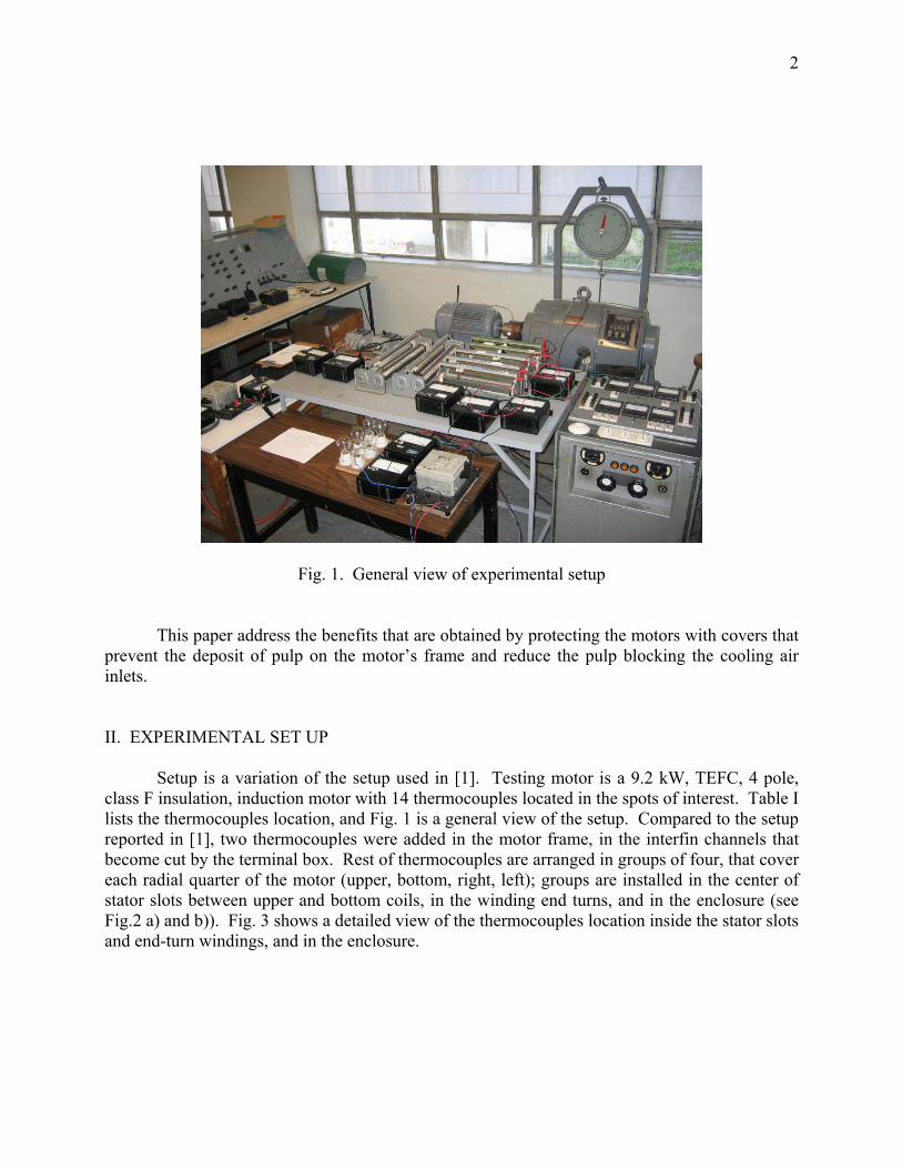
Fig. 1. General view of experimental setup
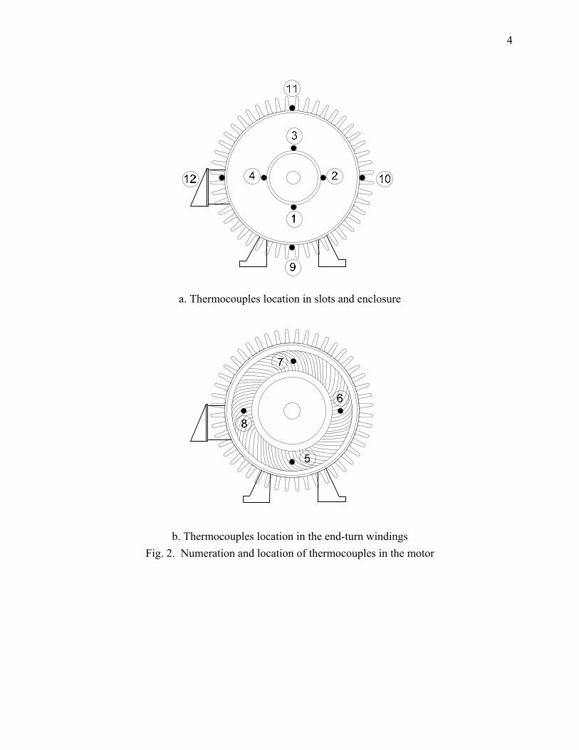
This paper address the benefits that are obtained by protecting the motors with covers that prevent the deposit of pulp on the motor’s frame and reduce the pulp blocking the cooling air inlets. II. EXPERIMENTAL SET UP Setup is a variation of the setup used in [1]. Testing motor is a 9.2 kW, TEFC, 4 pole, class F insulation, induction motor with 14 thermocouples located in the spots of interest. Table I lists the thermocouples location, and Fig. 1 is a general view of the setup. Compared to the setup reported in [1], two thermocouples were added in the motor frame, in the interfin channels that become cut by the terminal box. Rest of thermocouples are arranged in groups of four, that cover each radial quarter of the motor (upper, bottom, right, left); groups are installed in the center of stator slots between upper and bottom coils, in the winding end turns, and in the enclosure (see Fig.2 a) and b)). Fig. 3 shows a detailed view of the thermocouples location inside the stator slots and end-turn windings, and in the enclosure.
3
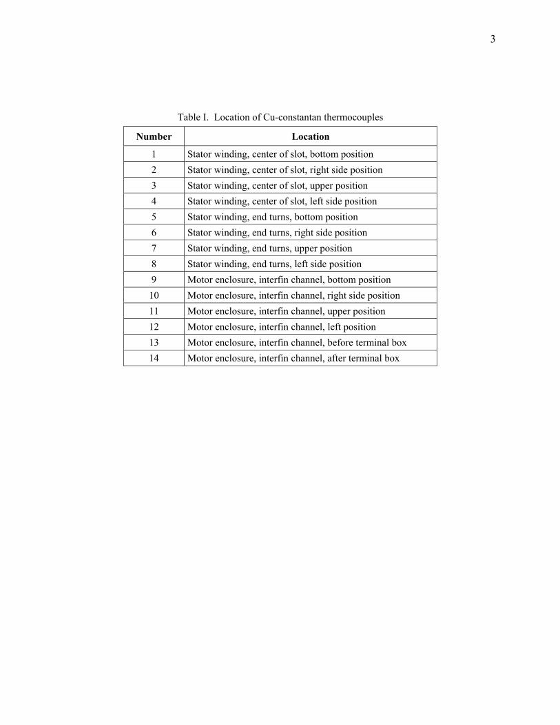
Table I. Location of Cu-constantan thermocouples
Number Location
1 Stator winding, center of slot, bottom position 2 Stator winding, center of slot, right side position 3 Stator winding, center of slot, upper position 4 Stator winding, center of slot, left side position 5 Stator winding, end turns, bottom position 6 Stator winding, end turns, right side position 7 Stator winding, end turns, upper position 8 Stator winding, end turns, left side position 9 Motor enclosure, interfin channel, bottom position
10 Motor enclosure, interfin channel, right side position 11 Motor enclosure, interfin channel, upper position 12 Motor enclosure, interfin channel, left position 13 Motor enclosure, interfin channel, before terminal box 14 Motor enclosure, interfin channel, after terminal box
4
a. Thermocouples location in slots and enclosure
b. Thermocouples location in the end-turn windings Fig. 2. Numeration and location of thermocouples in the motor
5
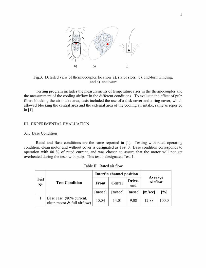
Fig.3. Detailed view of thermocouples location a). stator slots, b). end-turn winding, and c). enclosure
Testing program includes the measurements of temperature rises in the thermocouples and the measurement of the cooling airflow in the different conditions. To evaluate the effect of pulp fibers blocking the air intake area, tests included the use of a disk cover and a ring cover, which allowed blocking the central area and the external area of the cooling air intake, same as reported in [1]. III. EXPERIMENTAL EVALUATION 3.1. Base Condition Rated and Base conditions are the same reported in [1]. Testing with rated operating condition, clean motor and without cover is designated as Test 0. Base condition corresponds to operation with 80 % of rated current, and was chosen to assure that the motor will not get overheated during the tests with pulp. This test is designated Test 1.
Table II. Rated air flow
Interfin channel position
Front Center Drive-end
Average Airflow Test
Nº Test Condition
[m/sec] [m/sec] [m/sec] [m/sec] [%] 1 Base case (80% current,
clean motor & full airflow) 15.54 14.01 9.08 12.88 100.0
6
Table III. Temperature rise for rated and base case conditions
Radial Quarter Sector Test Nº
Thermocouples Location Upper Right Bottom Left
Average Temp. rise
Stator slots 90.7 92.2 92.6 101.3 94.20 End turns 107.1 105.2 107.3 109.7 107.33 Frame 40.0 39.5 42.1 39.8 40.35
0
DE bearing 43.0 Stator slots 60.7 62.0 62.1 68.0 63.20 End turns 70.9 69.9 71.4 73.0 71.30 Frame 27.1 26.7 28.9 27.0 27.43
1
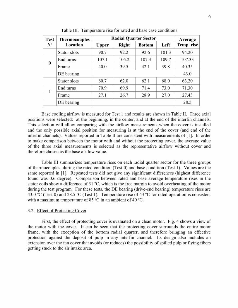
DE bearing 28.5 Base cooling airflow is measured for Test 1 and results are shown in Table II. Three axial positions were selected: at the beginning, in the center, and at the end of the interfin channels. This selection will allow comparing with the airflow measurements when the cover is installed and the only possible axial position for measuring is at the end of the cover (and end of the interfin channels). Values reported in Table II are consistent with measurements of [1]. In order to make comparison between the motor with and without the protecting cover, the average value of the three axial measurements is selected as the representative airflow without cover and therefore chosen as the base airflow value. Table III summarizes temperature rises on each radial quarter sector for the three groups of thermocouples, during the rated condition (Test 0) and base condition (Test 1). Values are the same reported in [1]. Repeated tests did not give any significant differences (highest difference found was 0.6 degree). Comparison between rated and base average temperature rises in the stator coils show a difference of 31 ºC, which is the free margin to avoid overheating of the motor during the test program. For these tests, the DE bearing (drive-end bearing) temperature rises are 43.0 ºC (Test 0) and 28.5 ºC (Test 1). Temperature rise of 43 ºC for rated operation is consistent with a maximum temperature of 85 ºC in an ambient of 40 ºC. 3.2. Effect of Protecting Cover First, the effect of protecting cover is evaluated on a clean motor. Fig. 4 shows a view of the motor with the cover. It can be seen that the protecting cover surrounds the entire motor frame, with the exception of the bottom radial quarter, and therefore bringing an effective protection against the deposit of pulp in any interfin channel. Its design also includes an extension over the fan cover that avoids (or reduces) the possibility of spilled pulp or flying fibers getting stuck to the air intake area.
7
Fig. 4. Clean motor with cover
Table IV. Airflow for clean motor with protecting cover
Average Airflow Test Nº Test Condition
[m/s] [%]
1 Base case (clean motor & full airflow) 12.88 100.0
2 Motor with cover & clear air intake area 16.79 130.39
Table V. Temperature rise for clean motor with cover
Radial Quarter Sector Test Nº
Thermocouples Location Upper Right Bottom Left
Average Temp. rise
Stator slots 59.1 59.2 59.7 67.4 61.35 End turns 68.6 68.1 69.7 71.5 69.48 Frame 24.2 24.2 24.5 24.5 24.35
2
DE bearing 28.1 The clean motor with cover was tested for the base operating condition and the airflow and temperature rises were measured. Test is designated as Test 2 and results are presented in Tables IV and V. Looking at Table IV, it can be seen that the overage airflow at the end of the cover (and fin channels) is 16.79 [m/sec], which is equivalent to 130.4 % the average airflow without cover. In addition, Table V shows that the average temperature rise in the winding end

8
turns is 69.5 ºC, which is 1.8 ºC below the average temperature rise without cover. Similar situations arise in the stator slots and frame where the average temperature rises are 1.9 ºC and 3.1 ºC below the values for the base condition. The temperature rise in the DE bearing is 28.1 ºC, 0.4 ºC less than the base case. All these results are consistent with expectations and demonstrate that the use of the cover, besides giving protection against pulp, improves the motor cooling a little bit. The extrapolation of the differences to rated conditions increases the expected reduction in the temperature rise in the winding to 2.7 ºC. 3.3. Effect of Pulp without Cover Next, the effect of pulp spilled over the motor, emulating an over flown tank, is evaluated. This was done pouring pulp over the entire motor. It was found that none of the pulp collects to the air inlets. This is explained because the clean motor surfaces are smooth and the wet pulp cannot stick to the almost vertical surface of air inlets. In field conditions, results should be different because the air intake area becomes dirty; the pulp fibers already collected will trap part of the wet pulp poured over the air intake, increasing the air inlet blocking. The test with pulp over the motor frame and clear air intake area is designated as Test 3. Fig. 5 shows the motor condition, and temperature rises are reported in Table VI. After Test 3 was completed, pulp was splashed over the air intake area, partially covering the air inlet holes. This situation tries to emulate a more realistic field condition, as well as the effect of hosing the area and splashing pulp in the air intake net. This condition is depicted in Fig. 6. Test is designated as Test 4, and results are shown in Table VI. According to these tables, the average temperature rise in the winding end turns in Test 3 is 74.15 ºC, which is 2.85 ºC higher than during base condition. For Test 4, which includes pulp splashed in the air intake, the average temperature in the winding end turns reaches 83.8 ºC that is 12.5 ºC over the base condition. Extrapolation of these values to rated condition, gives a temperature rise increase of 4.3 ºC and 18.8 ºC, respectively.

9
Fig. 5. Motor without cover and pulp spilled over it; clean air intake area
Fig. 6. Motor without cover with pulp spilled over it, and pulp splashed on the air intake area
10
Table VI. Temperature rise for motor without cover and pulp over it
Radial Quarter Sector Test Nº
Thermocouples Location Upper Right Bottom Left
Average Temp. rise
Stator slots 65.4 63.1 63.4 71.7 65.90 End turns 74.6 72.0 73.6 76.4 74.15 Frame 27.8 27.1 28.1 27.9 27.73
3
DE bearing 30.7 Stator slots 74.1 72.7 73.1 81.5 75.35 End turns 83.8 81.7 83.5 86.1 83.78 Frame 36.4 35.9 36.4 36.3 36.25
4
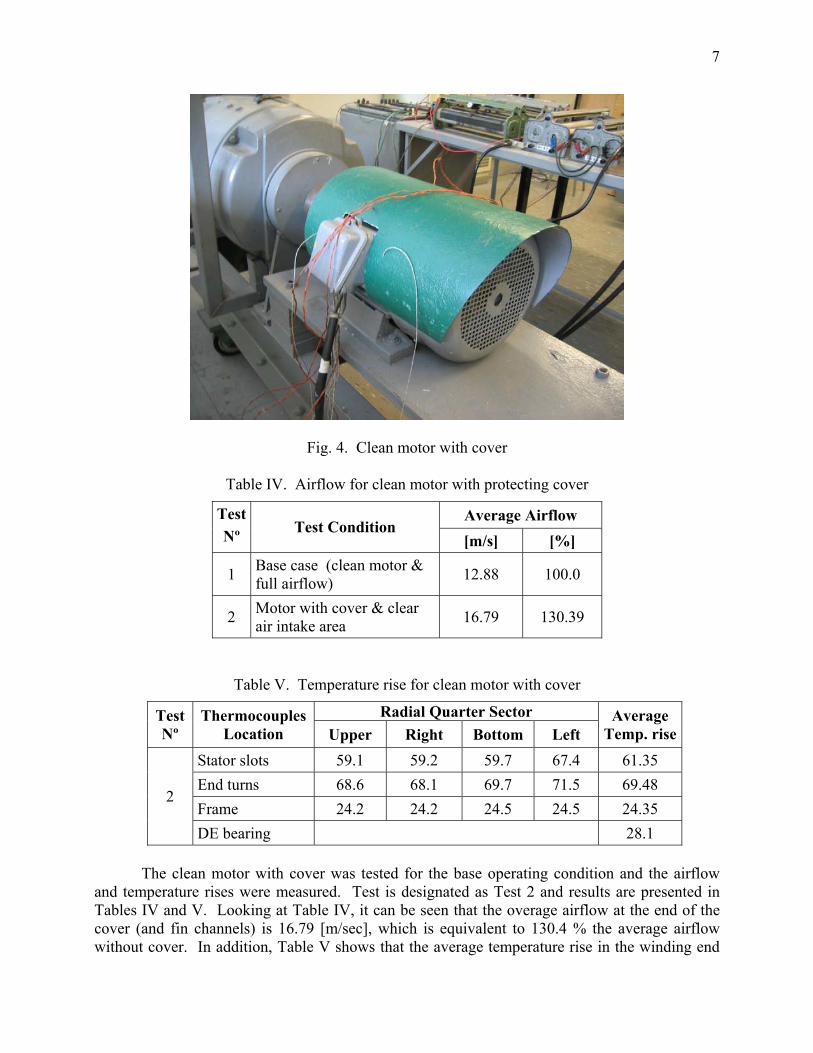
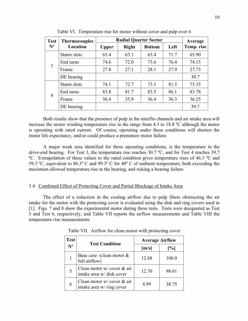
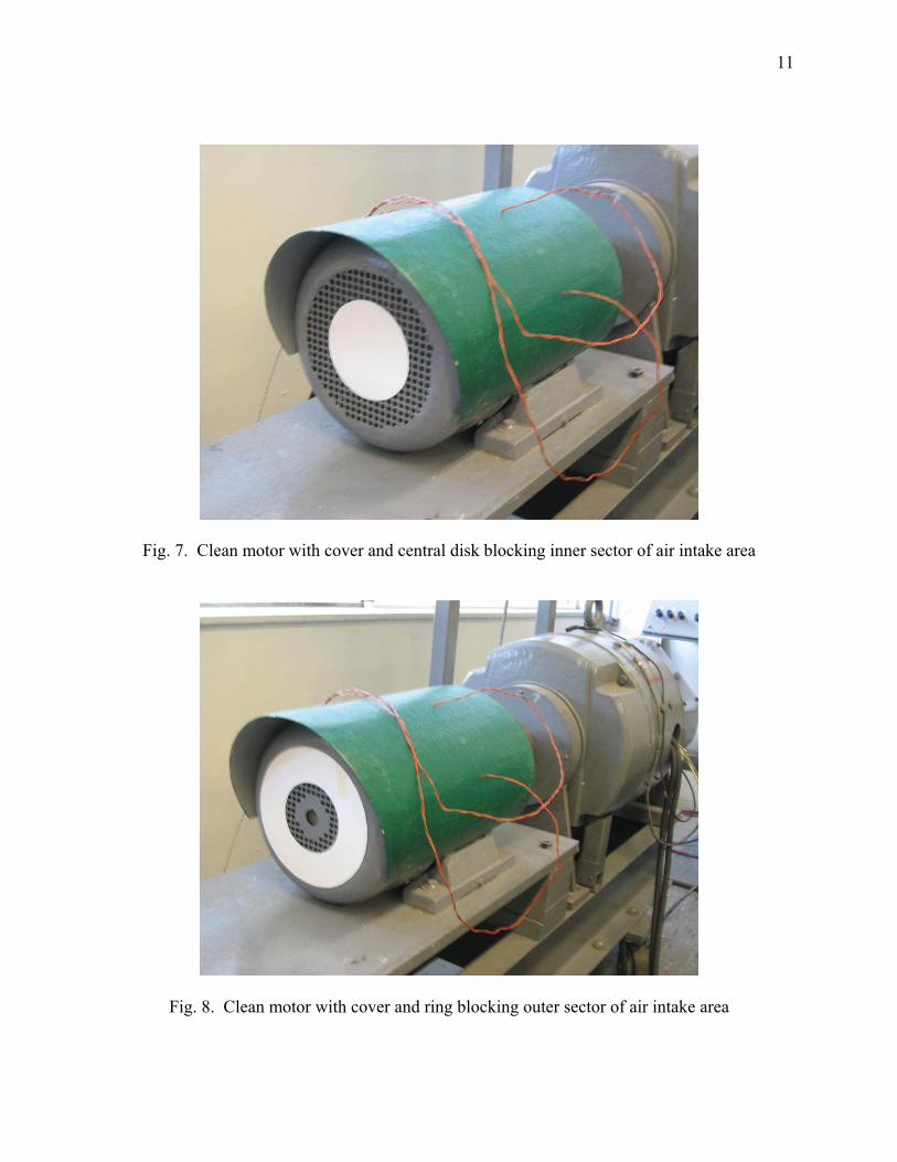
DE bearing 39.7 Both results show that the presence of pulp in the interfin channels and air intake area will increase the motor winding temperature rise in the range from 4.3 to 18.8 ºC although the motor is operating with rated current. Of course, operating under these conditions will shorten the motor life expectancy, and/or could produce a premature motor failure. A major weak area identified for these operating conditions, is the temperature in the drive-end bearing. For Test 3, the temperature rise reaches 30.7 ºC, and for Test 4 reaches 39.7 ºC. Extrapolation of these values to the rated condition gives temperature rises of 46.3 ºC and 59.3 ºC, equivalent to 86.3º C and 99.3º C for 40º C of ambient temperature, both exceeding the maximum allowed temperature rise in the bearing, and risking a bearing failure. 3.4. Combined Effect of Protecting Cover and Partial Blockage of Intake Area The effect of a reduction in the cooling airflow due to pulp fibers obstructing the air intake for the motor with the protecting cover is evaluated using the disk and ring covers used in [1]. Figs. 7 and 8 show the experimental motor during these tests. Tests were designated as Test 5 and Test 6, respectively, and Table VII reports the airflow measurements and Table VIII the temperature rise measurements.
Table VII. Airflow for clean motor with protecting cover
Average Airflow Test Nº Test Condition
[m/s] [%]
1 Base case (clean motor & full airflow) 12.88 100.0
5 Clean motor w/ cover & air intake area w/ disk cover 12.70 98.61
6 Clean motor w/ cover & air intake area w/ ring cover 4.99 38.75
11
Fig. 7. Clean motor with cover and central disk blocking inner sector of air intake area
Fig. 8. Clean motor with cover and ring blocking outer sector of air intake area
12
Table VIII. Temperature rise for clean motor with cover and disk/ring obstructing the air intake
Radial Quarter Sector Test Nº
Thermocouples Location Upper Right Bottom Left
Average Temp. rise
Stator slots 66.1 66.4 67.1 75.0 68.65 End turns 76.2 76.1 78.0 79.8 77.53 Frame 28.4 28.4 29.2 28.3 28.58
5
DE bearing 35.0 Stator slots 75.3 76.6 77.0 83.5 78.10 End turns 85.8 86.2 87.7 88.7 87.10 Frame 37.6 38.1 38.2 37.3 37.80
6
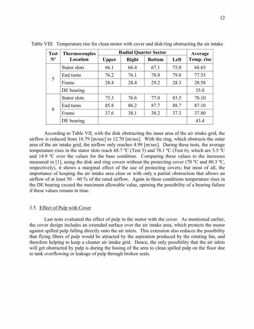
DE bearing 43.4 According to Table VII, with the disk obstructing the inner area of the air intake grid, the airflow is reduced from 16.79 [m/sec] to 12.70 [m/sec]. With the ring, which obstructs the outer area of the air intake grid, the airflow only reaches 4.99 [m/sec]. During these tests, the average temperature rises in the stator slots reach 68.7 ºC (Test 5) and 78.1 ºC (Test 6), which are 5.5 ºC and 14.9 ºC over the values for the base condition. Comparing these values to the increases measured in [1], using the disk and ring covers without the protecting cover (70 ºC and 80.3 ºC, respectively), it shows a marginal effect of the use of protecting covers; but most of all, the importance of keeping the air intake area clear or with only a partial obstruction that allows an airflow of at least 50 – 60 % of the rated airflow. Again in these conditions temperature rises in the DE bearing exceed the maximum allowable value, opening the possibility of a bearing failure if these values remain in time. 3.5. Effect of Pulp with Cover Last tests evaluated the effect of pulp in the motor with the cover. As mentioned earlier, the cover design includes an extended surface over the air intake area, which protects the motor against spilled pulp falling directly onto the air inlets. This extension also reduces the possibility that flying fibers of pulp would be attracted by the aspiration produced by the rotating fan, and therefore helping to keep a cleaner air intake grid. Hence, the only possibility that the air inlets will get obstructed by pulp is during the hosing of the area to clean spilled pulp on the floor due to tank overflowing or leakage of pulp through broken seals.
13
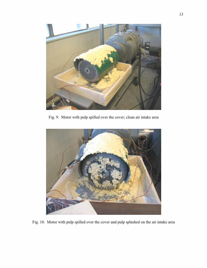
Fig. 9. Motor with pulp spilled over the cover; clean air intake area
Fig. 10. Motor with pulp spilled over the cover and pulp splashed on the air intake area
14
Table IX. Airflow for motor with protecting cover and pulp over it
Average Airflow Test Nº Test Condition
[m/s] [%]
1 Base case (clean motor & full airflow) 12.88 100.0
7 Motor with cover and pulp over it, clear air intake area 16.79 130.39
8 Motor with cover and pulp over cover and splashed in air intake area
8.90 69.10
Table X. Temperature rise for motor with cover and pulp over it
Radial Quarter Sector Test Nº
Thermocouples Location Upper Right Bottom Left
Average Temp. rise
Stator slots 60.0 60.2 61.1 68.3 62.40
End turns 69.5 69.2 71.1 72.8 70.65
Frame 24.7 24.2 25.3 24.8 24.75 7
DE bearing 28.2
Stator slots 69.0 70.1 70.5 77.8 71.85
End turns 78.9 78.4 80.5 81.9 79.93
Frame 31.2 31.3 32.0 30.9 31.35 8
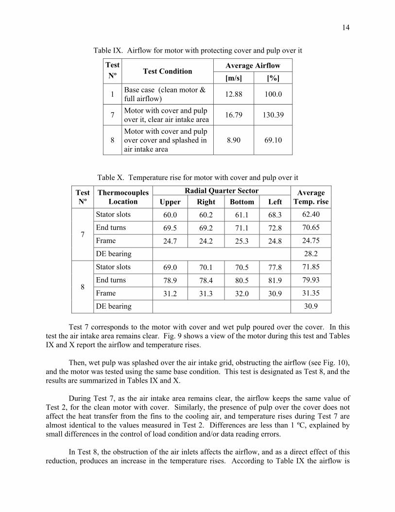
DE bearing 30.9 Test 7 corresponds to the motor with cover and wet pulp poured over the cover. In this test the air intake area remains clear. Fig. 9 shows a view of the motor during this test and Tables IX and X report the airflow and temperature rises. Then, wet pulp was splashed over the air intake grid, obstructing the airflow (see Fig. 10), and the motor was tested using the same base condition. This test is designated as Test 8, and the results are summarized in Tables IX and X. During Test 7, as the air intake area remains clear, the airflow keeps the same value of Test 2, for the clean motor with cover. Similarly, the presence of pulp over the cover does not affect the heat transfer from the fins to the cooling air, and temperature rises during Test 7 are almost identical to the values measured in Test 2. Differences are less than 1 ºC, explained by small differences in the control of load condition and/or data reading errors. In Test 8, the obstruction of the air inlets affects the airflow, and as a direct effect of this reduction, produces an increase in the temperature rises. According to Table IX the airflow is
15
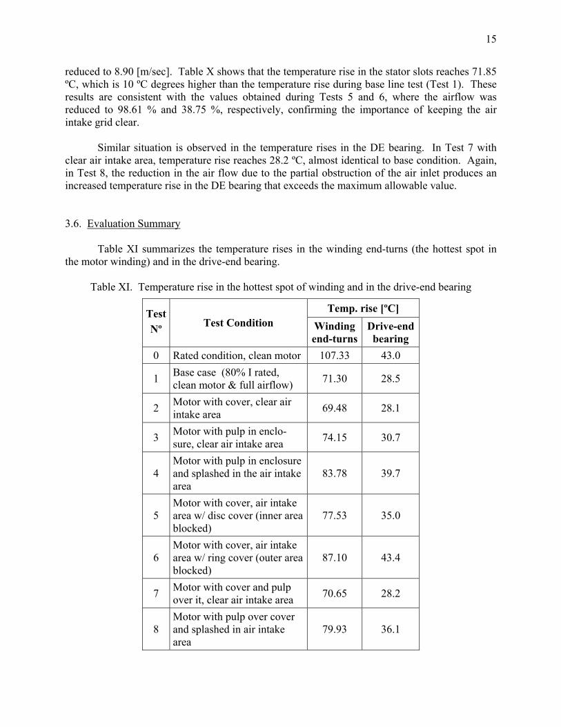
reduced to 8.90 [m/sec]. Table X shows that the temperature rise in the stator slots reaches 71.85 ºC, which is 10 ºC degrees higher than the temperature rise during base line test (Test 1). These results are consistent with the values obtained during Tests 5 and 6, where the airflow was reduced to 98.61 % and 38.75 %, respectively, confirming the importance of keeping the air intake grid clear. Similar situation is observed in the temperature rises in the DE bearing. In Test 7 with clear air intake area, temperature rise reaches 28.2 ºC, almost identical to base condition. Again, in Test 8, the reduction in the air flow due to the partial obstruction of the air inlet produces an increased temperature rise in the DE bearing that exceeds the maximum allowable value. 3.6. Evaluation Summary Table XI summarizes the temperature rises in the winding end-turns (the hottest spot in the motor winding) and in the drive-end bearing.
Table XI. Temperature rise in the hottest spot of winding and in the drive-end bearing
Temp. rise [ºC] Test Nº Test Condition Winding
end-turnsDrive-end bearing
0 Rated condition, clean motor 107.33 43.0
1 Base case (80% I rated, clean motor & full airflow) 71.30 28.5
2 Motor with cover, clear air intake area 69.48 28.1
3 Motor with pulp in enclo-sure, clear air intake area 74.15 30.7
4 Motor with pulp in enclosure and splashed in the air intake area
83.78 39.7
5 Motor with cover, air intake area w/ disc cover (inner area blocked)
77.53 35.0
6 Motor with cover, air intake area w/ ring cover (outer area blocked)
87.10 43.4
7 Motor with cover and pulp over it, clear air intake area 70.65 28.2
8 Motor with pulp over cover and splashed in air intake area
79.93 36.1
16
First, comparing the values for Test 0 and Test 1, it can be seen that temperature rises for rated condition are about 150% greater than in Test 1. This is consistent with the load condition of 80% for the base case, and the fact that the joule losses depend on the squared current. As stated earlier, load conditions used in Test 2 to Test 8 are the same of Test 1 (Base case, 80% of rated current). Therefore, values of each tested condition need to be compared to the values of Test 1. Extrapolation to rated load conditions can be made multiplying by the factor 1.5. Tests 2 and 7 show that the use of protecting covers, even with pulp over it, produces a slight reduction in the temperature rises, mainly due to the improved cooling of the enclosure by the confined airflow. For rated condition, the expected reduction should be around 2.5 – 3 ºC. Tests 5, 6 and 8 demonstrate that the benefit of the protecting cover vanishes if the air intake area becomes obstructed with pulp. In these conditions, both the internal winding temperatures and the DE bearing temperature, show great increases that extrapolated to rated load conditions should produce both a winding and a DE bearing failure. These results remark the importance of the cover shape that must avoid that poured or flying pulp fibers reach the air intake grid. IV. CONCLUSIONS In [1], the evaluation of the effect of pulp contamination on TEFC induction motors operating in the tank area of paper machines showed that pulp fibers obstructing the air flow through the inter-fin channels could produce temperature rise increases of about 7 – 9 ºC, and that the most important deteriorating effect is produced by obstructions in the air intake area. Specifically, for reductions of the air flow down to 40 – 35 % of the rated value, the average temperature rise in the winding could increase about 15 – 20 ºC. Recommendations were to oversize motor rating in about 20%, and oversize the DE bearing or use bearings with synthetic lubricants that allow higher operating temperatures. The evaluation of the effect of protecting covers done in this paper allows the following conclusions: i). The use of protecting covers avoid the possibility that pulp fibers reach and block the inter-
fin channels and, due to their extension over the air intake area, also avoid that spilled pulp or flying fibers reach and get stuck to the air intake grid, reducing the cooling air flow. Therefore, covers provide full protection for the two main causes of motor overheating due to pulp contamination.
ii). Covers have also beneficial effects on the motor cooling, confining the cooling air in the inter-fin channels. For rated operating conditions, the winding temperature rise is reduced about 2.5 – 3 ºC.

17
iii). In the event that pulp fibers get stuck and block the air intake area, the cooling air will drop
and the motor and DE bearing could become overheated. In these conditions, the benefit of protecting covers is just marginal.
iv). The only reasonable situation that could cause pulp to fibers reach the air intake grid of a motor protected with a cover is during the hosing of the floor in front of the motor. Therefore, to obtain full benefits of the protecting covers, hosing the floor right in front of the motor air intake grid, and water splashing over the air intake grid, should be avoided.
v). If these inconvenient practices are eliminated, the use of protecting covers will guarantee that motor cooling will not be affected by the contamination of pulp. As a consequence, there will be no need for oversizing the motor rating or using oversized or special DE bearings.
ACKNOWLEDGEMENTS Authors wish to thank Worthington Products, LLC, manufacturers of motor protective covers, for their support and help in this paper. REFERENCES [1] M. Aníbal Valenzuela, Milton Millar F., Juan A. Tapia, James A. Rooks, “Thermal Derating of
TEFC Induction Motors Coated or Partially Flooded by Spilled Pulp”, Conf. Rec. of 2004 IEEE Pulp and Paper Tech. Conf., Victoria, British Columbia, Canada, June 27 – July 1, 2004, pages: 8 - 14
[2] T. Albers, A. H. Bonnet, “Motor temperature considerations for Pulp & Paper mill applications”, in Conf. Rec. of 2002 Annual P & P Industry Tech. Conf., Toronto, Canada, June 2002, pp: 115-128
[3] R. P. Derrick, W. J. Martiny, W. J. McDonald, “Pulp Coated Motors: The Effect on Motor Life”, TAPPI Proceedings of 1986 Engineering Conference, pp: 27-39
[4] M. Aníbal Valenzuela, Paulus V. Verbakel, and James A. Rooks : “Thermal Evaluation for Applying TEFC Induction Motors on Short-time and Intermittent Duty Cycles”, IEEE Trans. on Industry Applications, Vol. 39, Nº 1, January/February 2003, pp: 45 – 52
[5] M. Aníbal Valenzuela, Juan Tapia L., James A. Rooks : “Thermal Evaluation of TEFC Induction Motors Operating on Frequency Controlled Variable Speed Drives”, IEEE Trans. on Industry Applications, Vol. 40, Nº 2, March/April 2004, pp: 692 – 698