effect of uniform and gradient thermal loading on
TRANSCRIPT
Journal of Civil Engineering and Construction Technology Vol. 4(3), pp. 90-103, March 2013 Available online at http://www.academicjournals.org/JCECT DOI: 10.5897/JCECT12.091 ISSN 2141-2634 ©2013 Academic Journals
Full Length Research Paper
Effect of uniform and gradient thermal loadings on cylindrical steel reservoirs (analytical investigation)
Mohammad Ebrahim Karbaschi
National Iranian Oil Company (NIOC), Iran. E-mail: [email protected].
Accepted 05 February, 2013
Circular steel reservoirs are used extensively for storing petroleum products, water and grains. Additional to uniform thermal loading, gradient thermal loading from sunshine varying angle during day and various seasons is one of important loadings that should be taken into account in design of these reservoirs. In this paper, using finite element modeling of cylindrical steel reservoirs with various height-to-diameter ratios with constant volume of reservoirs, thermal loading in two forms, uniform and gradient loads are applied, and, induced displacement and stresses are compared. Key words: Steel reservoirs, finite element modeling, thermal load, gradient load.
INTRODUCTION Circular reservoirs are extensively applied for storing liquids such as oil, water, wheat grains, etc. Usually these reservoirs are constructed from concrete or steel material and in circular or cubic forms. As interesting geometrical shape and wide application of cylindrical reservoirs, main researches on the storing reservoirs were focused on this form. In the field of effects of hydrostatic and seismic loads on reservoirs, numerous researches have been performed in previous researches/studies (Iranian building code 123, Iranian building code 312, ANSI A58.1, ACI 318-389) and their results are rebounded in design codes (Salajegheh et al., 2007; Fan and Jibin, 1994; Tedesco and Landis, 1982).
Thermal loading defined in the form of temperature loading (ΔT) is one of the important loading types behind hydrostatic, soil pressure and seismic loads which is pointed out in building codes (Iranian building code 312, ANSI A58.1, ACI 318-389). As some code recommendations, expansion joints and sliding restraint are suitable choices that would reduce thermal stresses considerably but, because of difficulties in water proofing joints of wall to foundation or walls together, applying these methods are becoming limited in practice.
In circular reservoirs like other radial symmetric structures, in addition to uniform thermal loading, gradient thermal loading on wall- as a function of varying sunshine angle during day and various seasons- is one of the important loading types in design of these reservoirs
whose importance is pointed out in some design codes (Iranian building code 123, Iranian building code 312). Although effects of uniform and gradient thermal loadings are investigated in some structural systems (Karbaschi et al., 2011; Alinia and Kashizadeh, 2006a, b), they are rarely studied for cylindrical reservoirs (Dehghan and Dehghani, 2011; Hoff et al., 1964).
The main aim of this research is to analytically investigate effect of uniform and gradient thermal loadings on induced stresses and displacements of steel reservoirs and effect of height to diameter ratio is regarded as an important parameter on the results.
In this way, finite element modeling of cylindrical steel reservoirs with various height to diameter ratios (H/D) with a constant volume of reservoir, is carried out and hydrostatic pressure and thermal loads in the forms of uniform and gradient are applied on the models as a function of radius-angle and results of analyses are compared with each other. METHODS OF STUDY
Finite element modeling of steel reservoirs is carried out in SAP2000 software. Four nodes, thin-shell element is applied for modeling wall and roof elements. Reservoirs were modeled in two forms; with and without roof. Their typical forms are shown in Figure 1. Volume of all reservoirs was assumed to be constantly 5000 m
3.
Height and diameter of four investigated models are shown in

Karbaschi 91
(a) (b)
Figure (1): finite element
Figure 1. Finite element modeling of cylindrical reservoirs, (a) without roof, (b) with roof.
Table 1. Height and diameter of steel models.
Model number Diameter (m) Height (m) Height/Diameter
1 23 12 0.52
2 25.2 10 0.4
3 28.2 8 0.28
4 32.6 6 0.18
Table 2. Property of steel reservoir models.
Module of elasticity (N/m
2)
FY (yield stress) N/m
2
(Poisson Ratio)
(Thermal coefficient)
Thickness (cm)
Restraint condition
2×10¹¹
2400×105 0.3 1.17×10
-5 2 Simply support
Table 1. Material property, thickness of elements and support conditions were assumed as presented in Table 2. Loading types For analyzing two thermal loading types the following procedures are regarded. Hydrostatic pressure To compare node displacements under thermal loadings with hydrostatic pressures, it is assumed in individual analyses that steel reservoirs are full of oil and the hydrostatic pressure is applied as P=γh where; P is hydrostatic pressure, γ is oil density (1400 kg/m
3)
and h is height of oil above the reference point. Due to wide application of cylindrical reservoirs for storing oil and other petroleum products, this liquid is regarded for investigating effect of hydrostatic pressure. Uniform temperature This type of thermal loading is simplest and has a usual form for applying thermal loading. Its value is assumed to be similar for inner
and outer layers of shell elements in the analyses. Schematically, state of reservoir in this state is illustrated in Figure 2a. Value of temperature is assumed to be 40°C for on-ground reservoirs according to the report from Water Concrete structures, 2005. This type of loading is applied for with and without roof models.
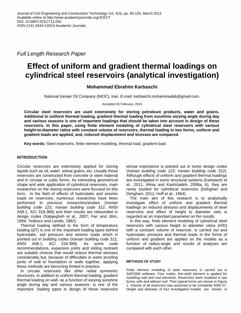
Gradient temperature as a function of radius angle In building codes (Iranian building code 312), it was stated that effect of non-uniform sunshine (inclined sun-shine) must be regarded appropriately in design of cylindrical reservoirs. For applying thermal loading that is induced from inclination in radiation to the object (Figure 2) gradient thermal model is defined as
)(10
CosT TT equation. Thus, there is maximum
temperature in shining side and the minimum value in backside; this decrease in temperature would be in the form of a gradient function with increasing radial angle (β). Maximal and minimal temperatures in this case are supposed to be 45
and 35°C respectively that its
average would be similar to uniform case of 40°C. For simplification, this case only was regarded for without roof reservoirs. Though difference between front and backside of reservoir may be more than 10°C
or maximum temperature might
exceed 45°C in the actual state (especially in the case that reservoir is empty), for comparing result of analyses under this type

92 J. Civ. Eng. Constr. Technol.
Figure 2. Schematic figure for shining direction and induced thermal loadings in (a) uniform and (b) gradient cases.
of loading with uniform thermal loading case, it was assumed that average of temperature is 40°C just as the uniform case.
As thin thickness of walls in the steel reservoirs, effect of gradient thermal loading in the thickness is ignorable.
ANALYSIS
Analyses are carried out statically under various forms of loading types as aforementioned loading types. To investigate effect of thermal loading, various parameters are studied as follows:
Radial base shear
Radial base shear value for unit length of wall restraints for various H/D was the same in both states including with and without roof cases under uniform thermal load. Value of radial base shear for various models for unit length of wall restraints are 52, 48.2, 43.9 and 39 (kN/m) for height/diameters as 0.52, 0.4, 0.28 and 0.18. Results of analyses show that with decrease in H/D and the constant volume of reservoir, base shear will decrease in unit length of restraint.
Displacements
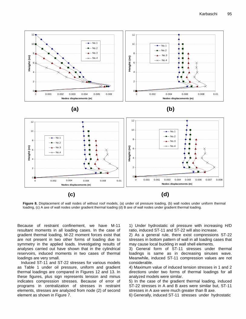
Wall node displacements under hydrostatic oil pressures, uniform and gradient thermal loadings are compared for various models in Figure 8. Uniform thermal load was applied on with and without roof reservoirs but two other loading types were applied only for without-roof state. Applying gradient thermal loading for with-roof reservoirs with defined equation in Figure 3 may take unrealistic thermal load distribution, and, in order to simplify this case, the respective loading was only applied for without-roof reservoirs. In the cases such as hydrostatic and
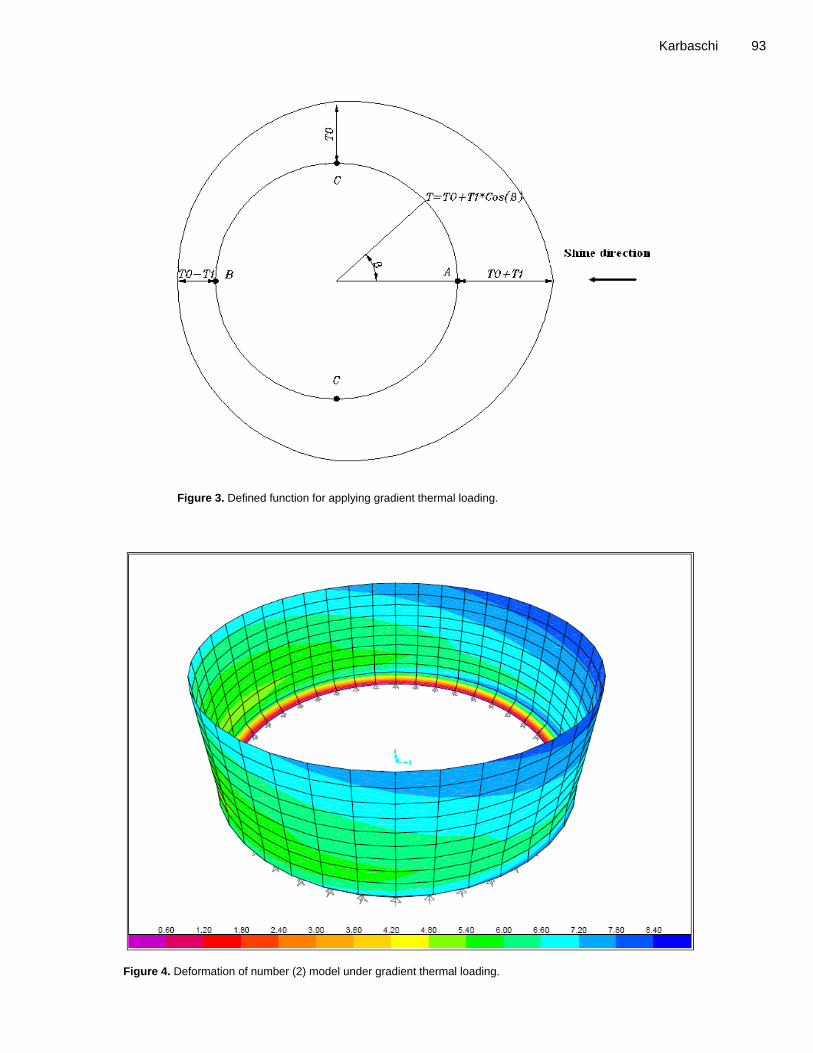
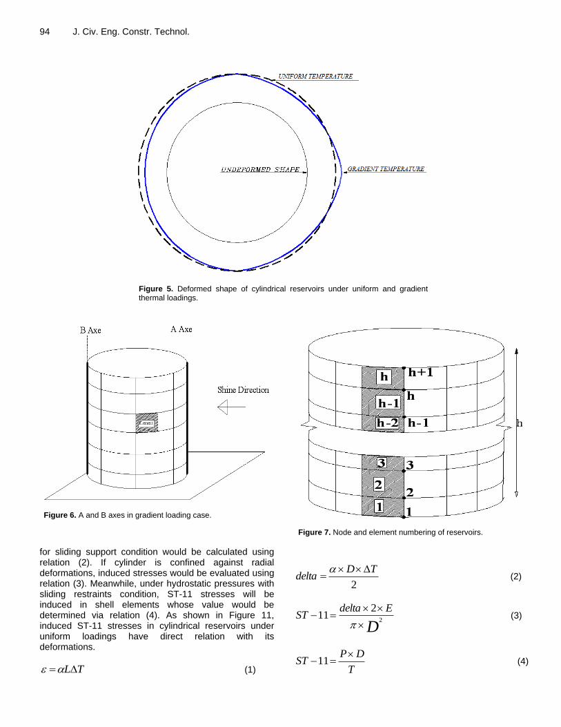
uniform thermal loadings in the cylindrical reservoirs where geometrical and loading symmetry exist, wall node displacements have direct relation with induced hoop stress in the wall elements. So, general form of wall deformation would conduct us to hoop stresses directly. But in gradient thermal loading case loading is not symmetrical and there would be inducing asymmetric stresses and moments. General form of reservoir deformation is shown in Figure 4. Schematic deformation under uniform and gradient thermal loading is illustrated in Figure 5. As asymmetrical gradient case, displacements and stresses are compared for A and B axes as Figure 6 displays. Condition of node and element numbering were as shown in Figure 7.
By comparing (9 and 12) diagrams, following conclusions can be inferred;
1) With increase in H/D, displacements of wall nodes will increase. Maximum of node displacements are in the height near to one meter from wall restraint for various H/D. 2) As a general rule, with increasing H/D, displacements will decrease in uniform and gradient thermal loading cases. Maximum wall node displacements in all analyses were near to wall restraint and in a constant height for various H/D ratios. 3) In the gradient thermal loading case, displacement of nodes in A-axis is about 1.25 times greater than B-axis.
Stresses
No stress would be induced in cylindrical reservoirs with sliding restraints under uniform thermal loading. General relation for thermal strain is as (1). Schematic figure for positive directions of moment and axial stresses in a shell element is shown in Figure 9. Therefore, delta (Figure 10)
Karbaschi 93
Figure 3. Defined function for applying gradient thermal loading.
Figure 4. Deformation of number (2) model under gradient thermal loading.
94 J. Civ. Eng. Constr. Technol.
Figure 5. Deformed shape of cylindrical reservoirs under uniform and gradient thermal loadings.
Figure 6. A and B axes in gradient loading case.
for sliding support condition would be calculated using relation (2). If cylinder is confined against radial deformations, induced stresses would be evaluated using relation (3). Meanwhile, under hydrostatic pressures with sliding restraints condition, ST-11 stresses will be induced in shell elements whose value would be determined via relation (4). As shown in Figure 11, induced ST-11 stresses in cylindrical reservoirs under uniform loadings have direct relation with its deformations.
TL (1)
Figure 7. Node and element numbering of reservoirs.
2
TDdelta
(2)
D
EdeltaST
2
211
(3)
T
DPST
11 (4)
Karbaschi 95
(a) (b)
(c) (d)
0
2
4
6
8
10
12
0 0.002 0.004 0.006 0.008 0.01 Nodes displacements (m)
No.1 No.2 No.3 No.4
Heig
ht
(m)
0
2
4
6
8
10
12
0 0.001 0.002 0.003 0.004 0.005 0.006 Nodes displacements (m)
No.1 No.2 No.3 No.4
Heig
ht
(m)
0
2
4
6
8
10
12
0 0.002 0.004 0.006 0.008 0.01 Nodes displacements (m)
No.1 No.2 No.3 No.4
Heig
ht
(m)
0
2
4
6
8
10
12
0 0.001 0.002 0.003 0.004 0.005 0.006 0.007 0.008 Nodes displacements (m)
No.1 No.2 No.3 No.4
Heig
ht
(m)
(a) (b)
(c) (d)
0
2
4
6
8
10
12
0 0.002 0.004 0.006 0.008 0.01 Nodes displacements (m)
No.1 No.2 No.3 No.4
He
igh
t (m
)
0
2
4
6
8
10
12
0 0.001 0.002 0.003 0.004 0.005 0.006 Nodes displacements (m)
No.1 No.2 No.3 No.4
He
igh
t (m
)
0
2
4
6
8
10
12
0 0.002 0.004 0.006 0.008 0.01 Nodes displacements (m)
No.1 No.2 No.3 No.4
He
igh
t (m
)
0
2
4
6
8
10
12
0 0.001 0.002 0.003 0.004 0.005 0.006 0.007 0.008 Nodes displacements (m)
No.1 No.2 No.3 No.4
He
igh
t (m
)
Figure 8. Displacement of wall nodes of without roof models, (a) under oil pressure loading, (b) wall nodes under uniform thermal loading, (c) A axe of wall nodes under gradient thermal loading (d) B axe of wall nodes under gradient thermal loading.
Because of restraint confinement, we have M-11 resultant moments in all loading cases. In the case of gradient thermal loading, M-22 moment forces exist that are not present in two other forms of loading due to symmetry in the applied loads. Investigating results of analyses carried out have shown that in the cylindrical reservoirs, induced moments in two cases of thermal loadings are very small.
Induced ST-11 and ST-22 stresses for various models as Table 1 under oil pressure, uniform and gradient thermal loadings are compared in Figures 12 and 13. In these figures, plus sign represents tension and minus indicates compression stresses. Because of error of programs in centralization of stresses in restraint elements, stresses are analyzed from node (2) of second element as shown in Figure 7.
1) Under hydrostatic oil pressure with increasing H/D ratio, induced ST-11 and ST-22 will also increase. 2) As a general rule, there exist compressions ST-22 stresses in bottom pattern of wall in all loading cases that may cause local buckling in wall shell elements. 3) General form of ST-11 stresses under thermal loadings is same as in decreasing sinuses wave. Meanwhile, induced ST-11 compression values are not considerable. 4) Maximum value of induced tension stresses in 1 and 2 directions under two forms of thermal loadings for all analyzed models were similar. 5) In the case of the gradient thermal loading, induced ST-22 stresses in A and B axes were similar but, ST-11 stresses in A axe were much greater than B axe. 6) Generally, induced ST-11 stresses under hydrostatic

96 J. Civ. Eng. Constr. Technol.
Figure 9. Axial stresses and moment forces of shell elements.
Figure 10. Deformation of wall under uniform thermal loading with sliding and simply restraint conditions.
oil pressure are much greater that thermal loadings but in the ST-22 case, they are similar. Effect of restraint condition To investigate effect of wall restraint conditions on wall node displacements and induced stresses in element, analyses performed for number (1) and (4) models under uniform thermal loading with simple and clamped restraint conditions. In simply support condition, restraint nodes rotation were realized but their translations were fixed but in clamped state all rotations and translations were fixed. Results of analyses are observed in Figures 14 and 15. These analyses suggest that as a general rule, increase in rotation confinement in wall restraints will reduce wall nodes displacement, and in result, hoop tension stresses. Also, increase in confinement will increase M-11 value and will change its sign in the restraint pattern. Effect of temperature value To investigate effect of temperature value in thermal loading on results of analyses, four temperature loads as T=10, 20, 30 and 40°C were applied on number (1) and (4) models. Wall node displacements for two models are compared in Figures 16 and 17.
These analyses reveal the fact that displacements and stresses have linear relationship with increase in temperature for various rise-to-span ratios. Consequently, if they are in hand for a certain temperature, they can be calculated for other temperature loading cases using linear interpolation.
Effect of wall thickness Taking into account that higher price of steel plates and exceeding weight and expenditures are caused by increase in thickness of the plates used, choosing appropriate thickness in design of circular reservoirs is very important. Main factor in choosing thickness are strength against induced stresses and stability against buckling. Displacement of wall nodes and induced ST-11 stresses in number (1) and (4) models are compared for 2, 4, 6 and 8 centimeter wall thicknesses in Figure 18. Through comparing diagrams the following conclusions can be expressed: 1) As a general rule, decrease in wall thickness will increase wall nodes displacements in low height, and, increasing height will increase displacements under uniform thermal loading assuming constant volume of reservoir.

Karbaschi 97
(a)
(b)
Figure 11. Cylindrical reservoirs under uniform internal pressure. (a): hydrostatic pressure on walls (b): ST-11 stresses in wall.

98 J. Civ. Eng. Constr. Technol.
(a) (b)
(c) (d)
50 100 150
Stress (kg/cm-2
) Stress (kg/cm-2
)
Stress (kg/cm-2
) Stress (kg/cm-2
)
Figure 12. Wall nodes stresses under (a): ST ST-11 stresses under oil pressure, (b): ST-22 stresses under oil pressure, (c): ST-22 stresses uniform thermal loading, (d): ST-11 stresses under uniform thermal loading.

Karbaschi 99
(a) (b)
(c) (d)
Stress (kg/cm-2
) Stress (kg/cm-2
)
Stress (kg/cm-2
) Stress (kg/cm-2
)
Figure 13. Wall nodes stresses under gradient thermal loading (a) ST-11 stresses of A axe, (b) ST-22 stresses of A axe, (c) ST-11 stresses of B axe, (d) ST-22 stresses of B axe.

100 J. Civ. Eng. Constr. Technol.
(a) (b)
(c) (d)
0
2
4
6
8
10
12
0 0.002 0.004 0.006 0.008 0.01 Nodes displacements (m)
No.1 No.2 No.3 No.4
He
igh
t (m
)
0
2
4
6
8
10
12
0 0.001 0.002 0.003 0.004 0.005 0.006 Nodes displacements (m)
No.1 No.2 No.3 No.4
He
igh
t (m
)
0
2
4
6
8
10
12
0 0.002 0.004 0.006 0.008 0.01 Nodes displacements (m)
No.1 No.2 No.3 No.4
He
igh
t (m
)
0
2
4
6
8
10
12
0 0.001 0.002 0.003 0.004 0.005 0.006 0.007 0.008 Nodes displacements (m)
No.1 No.2 No.3 No.4
He
igh
t (m
)
(a) (b)
(c) (d)
0
2
4
6
8
10
12
0 0.002 0.004 0.006 0.008 0.01 Nodes displacements (m)
No.1 No.2 No.3 No.4
Heig
ht
(m)
0
2
4
6
8
10
12
0 0.001 0.002 0.003 0.004 0.005 0.006 Nodes displacements (m)
No.1 No.2 No.3 No.4
Heig
ht
(m)
0
2
4
6
8
10
12
0 0.002 0.004 0.006 0.008 0.01 Nodes displacements (m)
No.1 No.2 No.3 No.4
Heig
ht
(m)
0
2
4
6
8
10
12
0 0.001 0.002 0.003 0.004 0.005 0.006 0.007 0.008 Nodes displacements (m)
No.1 No.2 No.3 No.4
Heig
ht
(m)
(a) (b)
(c) (d)
0
2
4
6
8
10
12
0 0.002 0.004 0.006 0.008 0.01 Nodes displacements (m)
No.1 No.2 No.3 No.4
He
igh
t (m
)
0
2
4
6
8
10
12
0 0.001 0.002 0.003 0.004 0.005 0.006 Nodes displacements (m)
No.1 No.2 No.3 No.4
He
igh
t (m
)
0
2
4
6
8
10
12
0 0.002 0.004 0.006 0.008 0.01 Nodes displacements (m)
No.1 No.2 No.3 No.4
He
igh
t (m
)
0
2
4
6
8
10
12
0 0.001 0.002 0.003 0.004 0.005 0.006 0.007 0.008 Nodes displacements (m)
No.1 No.2 No.3 No.4
He
igh
t (m
)
(a) (b)
(c) (d)
0
2
4
6
8
10
12
0 0.002 0.004 0.006 0.008 0.01 Nodes displacements (m)
No.1 No.2 No.3 No.4
Heig
ht
(m)
0
2
4
6
8
10
12
0 0.001 0.002 0.003 0.004 0.005 0.006 Nodes displacements (m)
No.1 No.2 No.3 No.4
Heig
ht
(m)
0
2
4
6
8
10
12
0 0.002 0.004 0.006 0.008 0.01 Nodes displacements (m)
No.1 No.2 No.3 No.4
Heig
ht
(m)
0
2
4
6
8
10
12
0 0.001 0.002 0.003 0.004 0.005 0.006 0.007 0.008 Nodes displacements (m)
No.1 No.2 No.3 No.4
Heig
ht
(m)
(a) (b)
(c) (d)
0
2
4
6
8
10
12
0 0.002 0.004 0.006 0.008 0.01 Nodes displacements (m)
No.1 No.2 No.3 No.4
He
igh
t (m
)
0
2
4
6
8
10
12
0 0.001 0.002 0.003 0.004 0.005 0.006 Nodes displacements (m)
No.1 No.2 No.3 No.4
He
igh
t (m
)
0
2
4
6
8
10
12
0 0.002 0.004 0.006 0.008 0.01 Nodes displacements (m)
No.1 No.2 No.3 No.4
He
igh
t (m
)
0
2
4
6
8
10
12
0 0.001 0.002 0.003 0.004 0.005 0.006 0.007 0.008 Nodes displacements (m)
No.1 No.2 No.3 No.4
He
igh
t (m
)
Figure 14. Displacement of number 1 and 4 model wall nodes with simply and clamped restraint condition under uniform thermal loading.
(a) (b)
(c) (d)
0
2
4
6
8
10
12
0 0.002 0.004 0.006 0.008 0.01 Nodes displacements (m)
No.1 No.2 No.3 No.4
Heig
ht (
m)
0
2
4
6
8
10
12
0 0.001 0.002 0.003 0.004 0.005 0.006 Nodes displacements (m)
No.1 No.2 No.3 No.4
Heig
ht (
m)
0
2
4
6
8
10
12
0 0.002 0.004 0.006 0.008 0.01 Nodes displacements (m)
No.1 No.2 No.3 No.4
Heig
ht (
m)
0
2
4
6
8
10
12
0 0.001 0.002 0.003 0.004 0.005 0.006 0.007 0.008 Nodes displacements (m)
No.1 No.2 No.3 No.4
Heig
ht (
m)
(a) (b)
(c) (d)
0
2
4
6
8
10
12
0 0.002 0.004 0.006 0.008 0.01 Nodes displacements (m)
No.1 No.2 No.3 No.4
Heig
ht
(m)
0
2
4
6
8
10
12
0 0.001 0.002 0.003 0.004 0.005 0.006 Nodes displacements (m)
No.1 No.2 No.3 No.4
Heig
ht
(m)
0
2
4
6
8
10
12
0 0.002 0.004 0.006 0.008 0.01 Nodes displacements (m)
No.1 No.2 No.3 No.4
Heig
ht
(m)
0
2
4
6
8
10
12
0 0.001 0.002 0.003 0.004 0.005 0.006 0.007 0.008 Nodes displacements (m)
No.1 No.2 No.3 No.4
Heig
ht
(m)
Figure 15. M-11 of number 1 and 4 model wall nodes with simply and clamped restraint condition under uniform thermal loading.

Karbaschi 101
0
2
4
6
8
10
12
0 0.001 0.002 0.003 0.004 0.005 0.006 0.007 Nodes displacements (m)
He
igh
t (m
)
(m)
T=10 T=20 T=30 T=40
Figure 16. Displacement of number 1 model wall nodes under various value of uniform thermal loading.
0
1
2
3
4
5
6
0 0.002 0.004 0.006 0.008 0.01 Nodes displacements (m)
He
igh
t (m
)
(m)
T=10 T=20 T=30 T=40
Figure 17. Displacement of number 4 model wall nodes under various value of uniform thermal loading.

102 J. Civ. Eng. Constr. Technol.
(a) (b)
(c) (d)
2
3
4
5
6
7
8
9
10
11
12
-50 0 50 100 150 200 250 300
stress (kg/cm^2)
Ele
men
t N
um
ber
t=2cm
t=4cm
t=6cm
t=8cm
2
2.5
3
3.5
4
4.5
5
5.5
6
-50 0 50 100 150 200 250
stress (kg/cm^2)
Ele
men
t N
um
ber
t=2cm
t=4cm
t=6cm
t=8cm
0
2
4
6
8
10
12
0 0.001 0.002 0.003 0.004 0.005 0.006 0.007 Nodes displacements (m)
He
igh
t (m
)
(m)
Thickness=2cm Thickness=4cm Thickness=6cm Thickness=8cm
0
1
2
3
4
5
6
0 0.002 0.004 0.006 0.008 Nodes displacements (m)
He
igh
t (m
)
(m)
Thickness=2cm Thickness=4cm Thickness=6cm thickness=8cm
Stress (kg/cm-2
) Stress (kg/cm-2
)
Figure 18. Displacement of wall nodes under uniform thermal loading with various wall thickness for (a) model 1, (b) model 2, (c) model 3, (d) model 4.
wall elements.
ACKNOWLEDGMENTS Author would like to thank National Iranian oil company (NIOC) and National Iranian South Oil Company (NISOC) for their help and financial support and Mr. S. Taghavipour, the Geology Assistance Manager of the
NISOC, for his supports. REFERENCES
Alinia MM, Kashizadeh S (2006a). "Effect of flexibility of substructures upon thermal behaviour of spherical double layer space truss domes. Part I: Uniform thermal loading". J. Constr. Steel Res. 62:359–368.
Alinia MM, Kashizadeh S (2006b). "Effect of flexibility of substructures upon thermal behavior of spherical double layer space truss domes. Part II: Gradient & partial loading". J. Constr. Steel Res. 62:675–681.
Dehghan AA, Dehghani AR (2011). Experimental and theoretical
investigation of thermal performance of underground cold-water reservoirs”. Int. J. Therm. Sci. 50(5):816.
Design and Calculations of On Ground Reservoirs (1995). Building code 123, 2th edition, management organization of country (IRAN.
Fan J, Jibin L (1994). “Dynamic stability of liquid storage cylindrical tanks subjected to horizontal seismic load excitation”. J. Appl. Math. Model. 18(7):373-383.
Hoff NJ, Chao CC, Madsen WA (1964). “Buckling of a thin-walled circular cylindrical shell heated along and axial strip.” J. Appl. Mech. 31:253-258.
Karbaschi ME, Goudarzizadeh R, Hedayat N (2011). "Efficiency of post-tensioning method for seismic retrofitting of pre-cast cylindrical concrete reservoirs”. Proc. 73
th World Academy of Science and
Technology, AUS, Doubei, pp. 821-825.
Karbaschi 103 Minimum Design Loads for Buildings and Other Structures (ANSI
A58.11982). American National Standard. Notes on ACI- 318-89 (1990). Portland Cement Association. Salajegheh J, Fan J, Jibin L, Tedesco W, Landis W (2007). Design of
on ground water reservoirs. Kerman University Publications. Structural Analysis Program (SAP) (2000). Nonlinear version 14.
Structural analysis program. Berkeley (CA): Computers and Structures Inc., 2009.
Tedesco, W, Landis W (1982). “Seismic analysis of cylindrical liquid storage tanks”. J. Comput. Struct. 32(5):1165-1174.
Ugural AC (1999). Stresses in plates and shells, Second Edition. Mc Graw-Hill.
Water Concrete Structures (2005). Building code 312, 29th edition
management organization of country (IRAN).