effect of viscous dissipation on mixed convection flow in
TRANSCRIPT

MultiCraft International Journal of Engineering, Science and TechnologyVol. 8, No. 3, 2016, pp. 27-47
INTERNATIONALJOURNAL OF
ENGINEERING,SCIENCE ANDTECHNOLOGYwww.ijest-ng.com
www.ajol.info/index.php/ijest 2016 MultiCraft Limited. All rights reserved
Effect of viscous dissipation on mixed convection flow in a vertical doublepassage channel using Robin boundary conditions
J. Prathap Kumar1, J.C. Umavathi2* and M. Karuna Prasad1
1Department of Mathematics, Gulbarga University, Kalaburagi-585 106, Karnataka, INDIA2Department of Engineering, University of Sannio, Piazza Roma 21, 82100 Benevento, ITALY
*Corresponding author E-mail: [email protected]
Abstract
The laminar fully developed flow in a vertical double passage channel filled with clear fluid has been discussed using Robinboundary conditions. The thin perfectly conductive baffle is inserted in the channel. The governing equations of the fluid whichare coupled and nonlinear are solved analytically by the perturbation method and semi analytically using differential transformmethod (DTM). The reference temperature of the external fluid is considered to be equal and different. The perturbation methodwhich is valid for small values of perturbation parameter is used to find the combined effects of buoyancy forces and viscousdissipation. The limitation imposed on the perturbation parameter is relaxed by solving the basic equations using differentialtransform method. The influence of mixed convection parameter, Biot number for symmetric and asymmetric wall temperatureson the velocity, temperature and the Nusselt number is explored at different positions of the baffle. The solutions obtained bydifferential transform method are justified by comparing with the solutions obtained by perturbation method and the solutionsagree very well for small values of the perturbation parameter.
Keywords: Baffle, Differential Transform Method, Perturbation Method, Viscous dissipation, Robin Boundary Conditions,Double passage channel.
DOI: http://dx.doi.org/10.4314/ijest.v8i3.4
1. Introduction
Mixed convection in ducted flow may occur in many applications, such as in heat exchangers, chemical processing equipmentand transport of heated or cooled fluids, solar collectors and microelectronic cooling. When the buoyancy opposes or aids theforced flow the flow reversal is observed near the duct wall. These flow reversals are of substantial significance because they maystrongly affect the wall friction, pressure drop, heat transfer, occurrence of entrance temperature, and stability of flow. Severalpapers on mixed convection in a parallel-plate vertical channel are available in the literature. Aung and Worku (1986) studied theboundary conditions of uniform wall temperatures. The effect of viscous dissipation on the velocity and on the temperatureprofiles has been analysed by Barletta (1998) for the boundary conditions of uniform wall temperatures. Mixed convection in avertical channel was also studied by Umavathi and her group (2006, 2009, 2010, 2011, 2013).
Attaching baffles to its vertical wall or horizontal walls partitions the enclosure. The flow characteristics of partitioned cavity arestudied recently by both numerical and experimental methods. Mixed convection flow through square vented enclosure withpartially heated bottom wall is often encountered in air-condition system. Air heating is one of the preferred methods forconditioning the room space especially in cold countries. With the increasing living standard, people pay special attention to theindoor air quality (IAQ), which is essential for the health of the people and work efficiency. To ensure better IAQ, a new airconditioning system with localized heat source and displacement ventilation has been proposed. The interaction between naturalconvection and forced convection is the main theme for displacement ventilation system. Mixed convection flow in an enclosure

Kumar et al. / International Journal of Engineering, Science and Technology, Vol. 8, No. 3, 2016, pp. 27-4728
was studied by Angirasa (2000) using isothermal wall conditions. Free and forced convection from a flush-mounted heat source onthe bottom of a horizontal rectangular enclosure was studied by Sumon Saha et al. (2006).
Salah-El-Din (1994) studied mixed convection problem in a vertical double passage channel. He claimed that the presence of thebaffle will lead to a higher value of Nusselt number depending on the baffle position and the value of the ratio of Grashof numberto Reynolds number. Experimental results by Datta and Datta (1998) also proved the enhancement of heat transfer with inclinedsolid and perforated baffles including the effects of baffle size, position and orientation. The experimental results by Chen andChen (1998) showed that the local heat transfer co-efficient decreases with an increase in the baffle wall gap for small bafflewidths whereas for large baffle widths the heat transfer co-efficient was increased. The effect of horizontal baffle on the heattransfer characteristics of opposing mixed convection in a vertical open channel was studied by Chang and Shiau (2005). Mixedconvection in a vertical channel saturated with porous medium was studied by Umavathi et al. (2014) in the presence of baffle andthey found that by increasing the porous parameter, rate of heat transfer was enhanced at both the walls. Prathap Kumar et al.(2011a,b) and Umavathi (2011) also studied convection in a vertical channel using different fluids by introducing a baffle.
In the literature we find that forced convection heat transfer in the thermal entrance region for a rectangular channel was studiedfor temperature boundary condition of first kind for prescribed wall temperature (Javeri, 1976), and for second kind for prescribedwall heat flux (Sparrow, 1960). However temperature boundary condition of third kind (the local wall heat flux is a linear functionof the local wall temperature) is more realistic in real field applications. Javeri (1977, 1978) studied the boundary condition ofthird kind for flow over a flat plate and in the thermal entrance region of a rectangular channel. The effect of viscous dissipationon mixed convection in a vertical channel using Robin boundary conditions was also studied by Zanchini (1998). Following thework of Zanchini (1998), Umavathi and Santosh (2012a,b) and Umavathi and Jaweria (2011a,b) and Umavathi et al. (2012)studied mixed convection in a vertical channel using Robin boundary conditions. Recently the influence of baffle for naturalconvection in a rectangular enclosure was studied by Sivasankaran and Kandaswamy (2007). Using power-law liquid,Hajmohammadi and Nourazar (2014) studied the effect of a thin gas layer in micro cylindrical Couette flows. The aim of thispaper is to extend the analysis performed by Zanchini (1998) by inserting perfectly conducting baffle using Robin boundaryconditions.
2. Formulation of the problem
Figure 1 displays the schematic diagram and the co-ordinates of the problem. The flow is assumed to be steady, laminar andfully developed. The perfectly thin baffle is inserted in the channel and hence we obtain two passages.
Figure 1: Schematic diagram and the coordinate system
DD
1T2T
Baffle
Y
X
g
Flow direction
Stream-I Stream-II
2
L
2
L

Kumar et al. / International Journal of Engineering, Science and Technology, Vol. 8, No. 3, 2016, pp. 27-4729
The physical properties such as thermal conductivity and viscosity are assumed to be constant. Density is assumed to be constantexcept when it is multiplied by the gravity and state equation also holds. The Navier-Stokes equations using the assumptions asmentioned above (following Zanzchini, 1998) become
Stream-I
2
11 0 2
0d UP
g T TX dY
(1)
Stream-II
2
22 0 2
0d UP
g T TX dY
(2)
and the momentum balance equation along Y direction in both the streams are
0P
Y
(3)
where
0P p g X (4)
(assuming equal pressure gradient in both the streams) is the difference between the pressure and the hydrostatic pressure.Equations (1) and (2) using Equation (4) becomeStream-I
2
11 0 2
0d UdP
g T TdX dY
(5)
Stream-II
2
22 0 2
0d UdP
g T TdX dY
(6)
Differentiating Equations (5) and (6) with respect to X and Y , one obtainsStream-I
21
2
1T d P
X g dX
(7)
31 1
3
T d U
Y g dY
(8)
2 41 12 4
T d U
Y g dY
(9)
Stream-II2
22
1T d P
X g dX
(10)
32 2
3
T d U
Y g dY
(11)
2 42 22 4
T d U
Y g dY
(12)
It is assumed that the thickness of the walls is negligible and exchange heat by convection with an external fluid. The external
convection coefficient at the left wall is 1h and at the right wall is 2h . It is also assumed that the temperature at the right wall is
greater than or equal to the temperature of the left wall. The boundary conditions on the temperature field are
1
11
2
, 2L
Y
Tk h T T X L
Y
(13)
22 2
2
, 2L
Y
Tk h T X L T
Y
(14)

Kumar et al. / International Journal of Engineering, Science and Technology, Vol. 8, No. 3, 2016, pp. 27-4730
Using Eqns. (8) and (11), Eqns.(13) and (14) become
3
1 113
2
, 2L
Y
d U g hT T X L
dY k
(15)
3
2 223
2
, 2L
Y
d U g hT X L T
dY k
(16)
Equations (7) and (10) suggest that there exists a constant A such thatdP
AdX (17)
The equation for the conservation of energy in the two passages areStream-I
221 12
d T dU
dY k dY
(18)
Stream-II22
2 22
d T dU
dY k dY
(19)
Equations (9) and (18) and Eqns. (12) and (19) yield differential equations for 1U and 2U as follows
Stream-I24
1 14
d U dUg
dY k dY
(20)
Stream-II24
2 24
d U dUg
dY k dY
(21)
The boundary conditions for the velocity in stream-I and stream-II are
1 2 02 2
L LU U
(22)
and together with Eqs. (15) and (16), which on account of (5) and (6) can be written as
3 2
1 1 1 1 10 13 2
2Y L
d U h d U Ah g hT T
dY k dY k k
(23)
3 2
2 2 2 2 22 03 2
2Y L
d U h d U Ah g hT T
dY k dY k k
(24)
In addition we consider the continuity of temperature 1 2T T and continuity of heat flux 1 2dT dT
dY dY
at the baffle position.
Applying these conditions in Eqns. (5), (6), (8) and (11) yield2 2
1 22 2
d U d U
dY dY (25)
and3 3
1 23 3
d U d U
dY dY (26)
Equations (20) and (21) which determine the velocity distribution along with the boundary conditions at the channel wallsand at the baffle position are non-dimensionalised using the following dimensionless parameters:
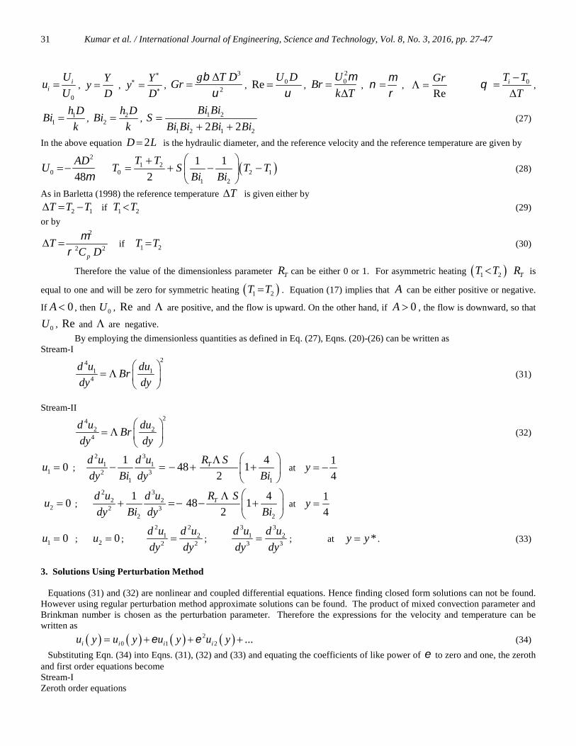
Kumar et al. / International Journal of Engineering, Science and Technology, Vol. 8, No. 3, 2016, pp. 27-4731
0
ii
Uu
U ,
Yy
D ,
Yy
D
,3
2
g T DGr
, 0ReU D
,
20U
Brk T
,
,
Re
Gr 0iT T
T
,
11
h DBi
k , 2
2
h DBi
k , 1 2
1 2 1 22 2
Bi BiS
Bi Bi Bi Bi
(27)
In the above equation 2D L is the hydraulic diameter, and the reference velocity and the reference temperature are given by
2
0 48
ADU
1 2
0 2 11 2
1 1
2
T TT S T T
Bi Bi
(28)
As in Barletta (1998) the reference temperature T is given either by
2 1T T T if 1 2T T (29)
or by2
2 2p
TC D
if 1 2T T (30)
Therefore the value of the dimensionless parameter TR can be either 0 or 1. For asymmetric heating 1 2T T TR is
equal to one and will be zero for symmetric heating 1 2T T . Equation (17) implies that A can be either positive or negative.
If 0A , then 0U , Re and are positive, and the flow is upward. On the other hand, if 0A , the flow is downward, so that
0U , Re and are negative.
By employing the dimensionless quantities as defined in Eq. (27), Eqns. (20)-(26) can be written asStream-I
241 1
4
d u duBr
dy dy
(31)
Stream-II24
2 24
d u duBr
dy dy
(32)
1 0u ;2 3
1 12 3
1 1
1 448 1
2Td u d u R S
dy Bi dy Bi
at
1
4y
2 0u ;2 3
2 22 3
2 2
1 448 1
2Td u d u R S
dy Bi dy Bi
at
1
4y
1 0u ; 2 0u ;2 2
1 22 2
d u d u
dy dy ;
3 31 2
3 3
d u d u
dy dy ; at *y y . (33)
3. Solutions Using Perturbation Method
Equations (31) and (32) are nonlinear and coupled differential equations. Hence finding closed form solutions can not be found.However using regular perturbation method approximate solutions can be found. The product of mixed convection parameter andBrinkman number is chosen as the perturbation parameter. Therefore the expressions for the velocity and temperature can bewritten as
20 1 2 ...i i i iu y u y u y u y (34)
Substituting Eqn. (34) into Eqns. (31), (32) and (33) and equating the coefficients of like power of to zero and one, the zerothand first order equations becomeStream-IZeroth order equations

Kumar et al. / International Journal of Engineering, Science and Technology, Vol. 8, No. 3, 2016, pp. 27-4732
4104
0d u
dy (35)
First order equations24
10114
dud u
dy dy
(36)
Stream-IIZeroth order equations
4204
0d u
dy (37)
First order equations24
20214
dud u
dy dy
(38)
The corresponding boundary conditions for both stream-I and stream-II areZeroth order
10 0u ;2 3
10 1012 3
1
1d u d uBc
dy Bi dy at
1
4y
20 0u ;2 3
20 2022 3
2
1d u d uBc
dy Bi dy at
1
4y
10 0u ; 20 0u ;2 2
10 202 2
d u d u
dy dy ;
3 310 203 3
d u d u
dy dy at *y y (39)
where
11
448 1
2TR s
BcBi
and 2
2
448 1
2TR s
BcBi
First order
11 0u ;2 3
11 112 3
1
10
d u d u
dy Bi dy at
1
4y
21 0u ;2 3
21 212 3
2
10
d u d u
dy Bi dy at
1
4y
11 0u ; 21 0u ;2 2
11 212 2
d u d u
dy dy ;
3 311 213 3
d u d u
dy dy at *y y (40)
The solutions of zeroth and first order Eqns. (35)-(38) using the boundary conditions (39) and (40) can be obtained and are notpresented.Nondimensionalisation of Eqs. (5) and (6) become
Stream-I2
11 2
148
d u
dy
(41)
Stream-II2
22 2
148
d u
dy
(42)
Using the solutions of the velocity field, the temperature field is computed.

Kumar et al. / International Journal of Engineering, Science and Technology, Vol. 8, No. 3, 2016, pp. 27-4733
4. Solutions Using Differential Transform Method
The Differential Transform Method was first introduced by Zhou (1986) who solved linear and nonlinear differential equations
in electric circuit analysis. This method constructs a semi-analytical numerical technique uses Taylor series expansion for the
solution of linear or nonlinear partial or ordinary differential equations in the form of a polynomial.
The differential transform of the thk derivative of the function ( )f y is defined as follows:
0
1 ( )[ ]
!
k
k
y y
d f yF k
k dy
(43)
where ( )f y is the original function and [ ]F k is the transformed function. Differential inverse transform of [ ]F k is defined as
follows:
00
( ) [ ]( )k
k
f y F k y y
(44)
which implies that the concept of differential transform method is derived from Taylor series expansion, although this method isnot able to evaluate the derivatives symbolically.The Differential Transform Method (DTM) has been applied to obtain the solutions of equations (31) and (32) by using theboundary conditions obtained in Eqn. (33).
1 1 10
( 1)( 2)( 3)( 4) [ 4] ( 1) [ 1]( 1) [ 1]r
s
r r r r u r Br r s u r s s u s
(45)
2 2 20
( 1)( 2)( 3)( 4) [ 4] ( 1) [ 1]( 1) [ 1]r
s
r r r r u r Br r s u r s s u s
(46)
The initial conditions are as follows
1[0] 1u a , 1[1] 2u a , 1[2] 3u a , 1[3] 4u a , 2[0] 1u b , 2[1] 2u b , 2[2] 3u b , 2[3] 4u b (47)
The numerical values of the constants a1, a2, a3, a4, b1, b2, b3, b4 can be find by using the transformed equations withboundary and interface conditions. The system of equations leads to the solutions by substituting obtained numerical values ofconstants.
5. Nusselt Number
The non-dimensional heat transfer coefficient known as Nusselt number is given by
dNu
dy
(48)
The Nusselt number at both left wall and right wall are calculated numerically for different values of several governing parametersand are given in the following Table 1.
Table 1: Values of Nusselt number at different positions of the baffle for
1 2500, 10, 1, 0.1TBi Bi R
0.25y
d
dy
0.25y
d
dy
y y -0.15 0.0 0.15 -0.15 0.0 0.15
100 1.43503 1.43111 1.43345 1.41849 1.43423 1.42377
250 1.43210 1.42998 1.42984 1.42210 1.42536 1.42670
500 1.43155 1.43048 1.42948 1.42247 1.42485 1.42726

Kumar et al. / International Journal of Engineering, Science and Technology, Vol. 8, No. 3, 2016, pp. 27-4734
Table 1 (cont’d): Values of Nusselt number at different positions of the baffle for
1 2500, 10, 1, 0.1TBi Bi R
0.25y
d
dy
0.25y
d
dy
y y -0.15 0.0 0.15 -0.15 0.0 0.15
0 1.42857 1.42857 1.42857 1.42857 1.42857 1.42857
0.1 1.43155 1.43048 1.42948 1.42247 1.42485 1.42726
0.5 1.44344 1.43813 1.43311 1.39805 1.40998 1.42200
1Bi1 0.62572 0.62527 0.62529 0.62112 0.62322 0.62369
5 1.25229 1.25132 1.25065 1.24438 1.24673 1.24874
10 1.43155 1.43048 1.42948 1.42247 1.42485 1.42726
2Bi1 0.628309 0.62642 0.62619 0.62370 0.62437 0.62459
5 1.25328 1.25189 1.25089 1.24537 1.24730 1.24898
10 1.43155 1.43048 1.42948 1.42247 1.42485 1.42726
6. Results and discussion
In this paper, we have analyzed the problem of mixed convection flow in a vertical channel filled with purely viscous fluid usingRobin boundary conditions by introducing a perfectly thin conducting baffle. The analytical solutions are obtained using regularperturbation method with the product of ratio of Grashof number to Reynolds number and Brinkman number as the perturbation
parameter ReBr Gr which is valid for small values of perturbation parameter. This restriction is relaxed by finding
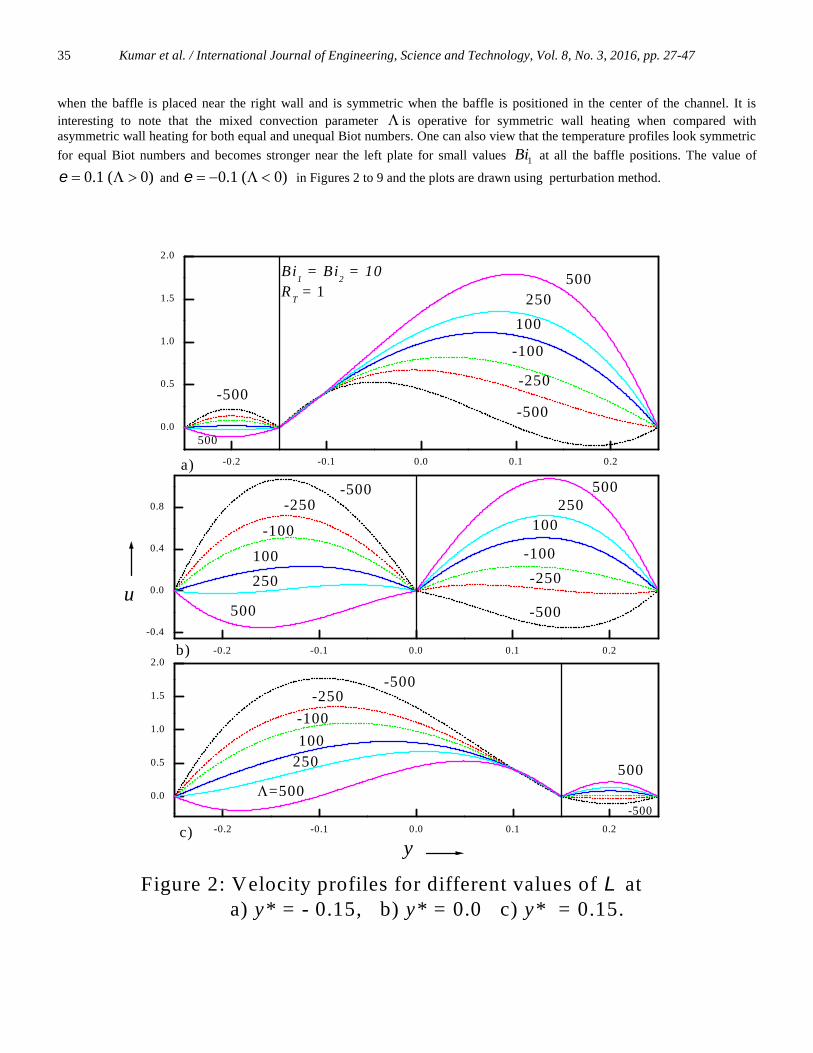
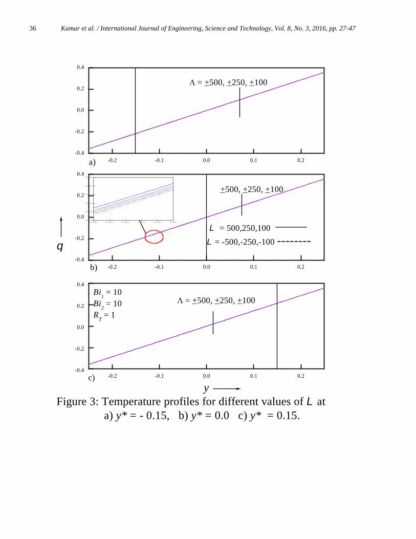
the solutions the using semi-numerical method known as differential transform method ((DTM). The combined effects ofbuoyancy and viscous dissipation on the momentum and heat transfer are analyzed and discussed for symmetric and asymmetricwall temperatures at different positions of the baffle. Figures 2 and 3 show the variations of the non-dimensional velocity andtemperature fields for different values of mixed convection parameter for equal Biot numbers. For buoyancy assisting flow
0 , the velocity increases in stream-II, for buoyancy opposing flow 0 and the velocity increases in stream-I as increases at all the baffle positions. As the mixed convection parameter increases, the reversal of flow increases at both theplates. Flow reversal is observed near the left wall (cold wall) for 0 and near the right wall for 0 . This is because, the
mixed convection parameter is the ratio of Grashof number to Reynolds number and therefore increasing implies increaseof the buoyancy force and hence flow is enhanced for 0 and retarded for 0 at all the baffle positions. Figure 3 display
the temperature profiles for different values of and it is seen that the temperature field is not much affected for the variations of at all the baffle positions. However, when the graph is enlarged it is seen that temperature increases in the upward direction for
0 and in downward direction for 0 . The magnitude of temperature for buoyancy assisting flow is more when compare
to buoyancy opposing flow. Figures 4 and 5 are the plots of velocity and temperature fields for variations of for unequal Biot numbers for asymmetricwall heating. The effect of on the flow for unequal Biot numbers show the similar nature as that of equal Biot numbers exceptthat the magnitude of flow reversal is less for unequal Biot numbers when compare to equal Biot numbers. This is due to the factthat, the value of S becomes 339.5 for equal Biot numbers and the value of S becomes 249.99 for unequal Biot numberswhich implies that the convection is reduced for unequal Biot numbers. For unequal Biot numbers also the temperature field isnot much affected by the variations of . In order to know the effect of distribution of velocity and temperature for symmetricheating, the profiles are drawn for equal and unequal Biot numbers in Figures 6 to 9 at different baffle positions. It is seen fromFigures 6 and 8 that the velocity field is not affected by the variations of at all the baffle positions for both equal and unequal
Biot numbers. The magnitude of velocity field for buoyancy assisted 0 flow is more when compared with buoyancy
opposing 0 flow. Further the optimal velocity is attained in stream-II when the baffle is near the left wall, in stream-II
Kumar et al. / International Journal of Engineering, Science and Technology, Vol. 8, No. 3, 2016, pp. 27-4735
when the baffle is placed near the right wall and is symmetric when the baffle is positioned in the center of the channel. It isinteresting to note that the mixed convection parameter is operative for symmetric wall heating when compared withasymmetric wall heating for both equal and unequal Biot numbers. One can also view that the temperature profiles look symmetric
for equal Biot numbers and becomes stronger near the left plate for small values 1Bi at all the baffle positions. The value of
0.1 ( 0) and 0.1 ( 0) in Figures 2 to 9 and the plots are drawn using perturbation method.
-0.2 -0.1 0.0 0.1 0.2
0.0
0.5
1.0
1.5
2.0
-0.2 -0.1 0.0 0.1 0.2
0.0
0.5
1.0
1.5
2.0
-0.2 -0.1 0.0 0.1 0.2
-0.4
0.0
0.4
0.8
=500500
-500
-500-250
-100
100250
b)
Bi1 = Bi
2 = 10
RT = 1
500
500
-500
100
250
c)
u
y
-500
-250
-100
a)
Figure 2: Velocity profiles for different values of at a) y* = - 0.15, b) y* = 0.0 c) y* = 0.15.
-100
-250
100
250
500 -500
250100-100
-250-500 500
Kumar et al. / International Journal of Engineering, Science and Technology, Vol. 8, No. 3, 2016, pp. 27-4736
-0.2 -0.1 0.0 0.1 0.2-0.4
-0.2
0.0
0.2
0.4
-0.2 -0.1 0.0 0.1 0.2-0.4
-0.2
0.0
0.2
0.4
-0.2 -0.1 0.0 0.1 0.2-0.4
-0.2
0.0
0.2
0.4
Figure 3: Temperature profiles for different values of at a) y* = - 0.15, b) y* = 0.0 c) y* = 0.15.
= +500, +250, +100
= 500,250,100
= -500,-250,-100
c)
b)
a)
_____
--------
+500, +250, +100
0 . 1 0 5 0 0 .1 0 5 2 0 . 1 0 5 4 0 . 1 0 5 6 0 .1 0 5 8 0 . 1 0 6 00 . 1 5 0 0
0 . 1 5 0 5
0 . 1 5 1 0
0 . 1 5 1 5
0 . 1 5 2 0
0 . 1 5 2 5
Bi1 = 10
Bi2 = 10
RT = 1
= +500, +250, +100
y

Kumar et al. / International Journal of Engineering, Science and Technology, Vol. 8, No. 3, 2016, pp. 27-4737
-0.2 -0.1 0.0 0.1 0.2
0.0
0.4
0.8
1.2
-0.2 -0.1 0.0 0.1 0.2
0.0
0.2
0.4
0.6
-0.2 -0.1 0.0 0.1 0.2
0.0
0.4
0.8
1.2
a)
u
Bi1 = 1
Bi2 = 10
RT = 1
=500
-500
500
Figure 4: Velocity profiles for different values of a) y* = - 0.15, b) y* = 0.0 c) y* = 0.15.
yc)
b)
100500
-250
-100
-100
250
-500
100
-500
-250
-100
500
250
100
250-250-500
-500
500
250
-250-500

Kumar et al. / International Journal of Engineering, Science and Technology, Vol. 8, No. 3, 2016, pp. 27-4738
-0.2 -0.1 0.0 0.1 0.2
-0.1
0.0
0.1
-0.2 -0.1 0.0 0.1 0.2
-0.1
0.0
0.1
-0.2 -0.1 0.0 0.1 0.2
-0.1
0.0
0.1
c)
b)
a)
+500, +250, +100
--------
_____ = 500,250,100
= -500,-250,-100
Figure 5: Temperature profiles for different values of a) y* = - 0.15, b) y* = 0.0 c) y* = 0.15.
Bi1 = 1
Bi2 = 10
RT = 1
+500, +250, +100
= +500, +250, +100
y

Kumar et al. / International Journal of Engineering, Science and Technology, Vol. 8, No. 3, 2016, pp. 27-4739
-0.2 -0.1 0.0 0.1 0.2
0.0
0.2
0.4
0.6
0.8
1.0
-0.2 -0.1 0.0 0.1 0.2
0.0
0.1
0.2
0.3
0.4
-0.2 -0.1 0.0 0.1 0.2
0.0
0.2
0.4
0.6
0.8
1.0
Figure 6: Velocity profiles for different values of a) y* = - 0.15, b) y* = 0.0 c) y* = 0.15.
u
c)
b)
a)
= -500, -250, -100
= 500, 250, 100
-0.090 -0.0850.91
0.92
0.93
Bi1 = 10
Bi2 = 10
RT = 0
= +500, +250, +100
= +500, +250, +100
y

Kumar et al. / International Journal of Engineering, Science and Technology, Vol. 8, No. 3, 2016, pp. 27-4740
-0.2 -0.1 0.0 0.1 0.20.0000
0.0004
0.0008
0.0012
-0.2 -0.1 0.0 0.1 0.2
0.0002
0.0004
0.0006
-0.2 -0.1 0.0 0.1 0.20.0000
0.0004
0.0008
0.0012
Bi1 = 10, Bi
2 = 10
RT = 1
yc)
Figure 7: Temperature profiles for different values of at a) y* = - 0.15, b) y* = 0.0 c) y* = 0.15.
b)
a)
=+100
+250
+500
+500
+250
+100
= +500
+250
+100

Kumar et al. / International Journal of Engineering, Science and Technology, Vol. 8, No. 3, 2016, pp. 27-4741
-0.2 -0.1 0.0 0.1 0.2
0.0
0.2
0.4
0.6
0.8
1.0
-0.2 -0.1 0.0 0.1 0.20.0
0.1
0.2
0.3
0.4
-0.2 -0.1 0.0 0.1 0.2
0.0
0.2
0.4
0.6
0.8
1.0
Figure 8: Velocity profiles for different values of a) y* = - 0.15, b) y* = 0.0 c) y* = 0.15.
c)y
u
=-100,-250,-500-0 .0 9 0 -0 . 0 8 5
0 . 9 1
0 . 9 2
0 . 9 3
b)
a)
=100,250,500
= +500, +250, +100
Bi1 = 1
Bi2 = 10
RT = 0
= +500, +250, +100

Kumar et al. / International Journal of Engineering, Science and Technology, Vol. 8, No. 3, 2016, pp. 27-4742
-0.2 -0.1 0.0 0.1 0.20.000
0.001
0.002
-0.2 -0.1 0.0 0.1 0.2
0.0004
0.0008
0.0012
-0.2 -0.1 0.0 0.1 0.20.000
0.001
0.002
0.003
Bi1 = 1, Bi
2 = 10
RT = 0
c)
b)
Figure 9: Temperature profiles for different values of at a) y* = - 0.15, b) y* = 0.0 c) y* = 0.15.
y
a)
+500
+250
+100
+500
+250
+100
= +500
+250
+100

Kumar et al. / International Journal of Engineering, Science and Technology, Vol. 8, No. 3, 2016, pp. 27-4743
-0.2 -0.1 0.0 0.1 0.2
0.0
0.4
0.8
1.2
1.6
2.0
-0.2 -0.1 0.0 0.1 0.2
-0.4
0.0
0.4
0.8
1.2
-0.2 -0.1 0.0 0.1 0.2
0
1
2
3
50.1
-0.1-5
0.1
5
-5
-5
-5
-0.1-5
5
0.1
DTM
PM
0.1
5
-0.1
-0.1
-0.1
c)
b)
a)
Figure 10: Velocity profiles for different values of and at a) y* = - 0.15, b) y* = 0.0 c) y* = 0.15.
u
y
Bi1 = Bi
2 = 10
RT = 1
50.1
-5-0.1
0.1
=5

Kumar et al. / International Journal of Engineering, Science and Technology, Vol. 8, No. 3, 2016, pp. 27-4744
-0.2 -0.1 0.0 0.1 0.2-0.4
-0.2
0.0
0.2
0.4
-0.2 -0.1 0.0 0.1 0.2-0.4
-0.2
0.0
0.2
0.4
-0.2 -0.1 0.0 0.1 0.2-0.4
-0.2
0.0
0.2
0.4
= -5, 5, -0.1, 0.1,
y
PMDTM
= -5, 5, -0.1, 0.1,- 0 . 1 4 5 - 0 . 1 4 0
- 0 . 2 1
- 0 . 2 0
- 0 . 1 9
- 0 . 1 8
5
- 55- 5
+ 0 . 1
Bi1 = Bi
2 = 10
RT = 1
= -5, 5, -0.1, 0.1,
c)
b)
a)
Fig.11. Temperature profiles for different values of and at a) y* = - 0.15, b) y* = 0.0 c) y* = 0.15.
In order to know the flow nature for large values of , the solutions are obtained using DTM and shown in Figures 10 and 11
for asymmetric wall heating and for equal Biot numbers. It is seen from these figures that for upward flow ( 0) velocity and
temperature are increasing functions of and for downward flow ( 0) velocity is a decreasing function of and temperature
is an increasing function of . One can also conclude from Figures 10 and 11 that the solutions obtained by DTM and PM agree
very well for values 1 and the error increases as increases. The effects of mixed convection parameter on the flow for
equal and unequal Biot numbers for 0.1 is the similar result observed by Zanchini (1998) in the absence of baffle.

Kumar et al. / International Journal of Engineering, Science and Technology, Vol. 8, No. 3, 2016, pp. 27-4745
To understand the physical significance, the rate of heat transfer is evaluated for variations of mixed convection parameter,perturbation parameter and Biot numbers at different positions of the baffle at both the plates. It is seen that as the perturbation
parameter , and the Biot numbers increases 1 2,Bi Bi rate of heat transfer increases and it decreases as the mixed convection
parameter 0 increases at the left plate at all the baffle positions. The rate of heat transfer increases as 0increases at 0.15y and 0.15y and decreases slightly 0.0y at the right plate. As the perturbation parameter
increases rate of heat transfer decreases whereas the reversal effect is observed for increasing values of Biot numbers at all thebaffle positions at the right plate.
7. Conclusion
The effect of mixed convection parameter, equal and unequal Biot numbers and perturbation parameter using Robin boundaryconditions in a vertical double passage channel was analysed. The solutions were found using regular perturbation method anddifferential transform method. For buoyancy assisting flow, the velocity increases in stream-II and for buoyancy opposing flow,the velocity increases in stream-I at all baffle positions. The velocity and temperature increases as the perturbation parameterincreases for buoyancy assisting flow whereas velocity increases, temperature increases for buoyancy opposing flow at all thebaffle positions. Temperature profiles were symmetric for equal Biot numbers and becomes stronger near the left plate for small
values of 1Bi . The Nusselt number increases at the left plate and decreases at the right plate as the perturbation parameter
increases, whereas it increases at both the plates for increasing Biot numbers. The solutions obtained by the perturbation methodand differential transform method were close for small values of the perturbation method. The results agreed very well withZanchini (1998) in the absence of baffle. It is observed that there is an enhancement of the heat transfer in the channel byintroducing the baffle and hence lot of research work can be done for the convection flow problems by introducing baffles.
Acknowledgment
One of the authors, J.C. Umavathi, is thankful for the financial support under the UGC-MRP F.43-66/2014 (SR) Project and alsoto Prof. Maurizio Sasso, supervisor and Prof. Matteo Savino co-coordinator for their support to do Post-Doctoral researchunder the scheme of ERUSMUS MUNDUS “Featured eUrope and South/south-east Asia mobility Network FUSION”
Nomenclature
P dimensional pressureK thermal conductivity
pC specific heat at constant pressure
u velocity
temperature
Gr Grashof number 3 2g h T
Re Reynolds number 0h U
Br Brinkman number 0U K T g acceleration due to gravity
0U reference velocity
T reference temperatureGreek Symbols thermal diffusivity coefficient of thermal expansion
T difference in temperature 2 1T T dimensionless parameter
non-dimensional temperature viscosity
kinematics viscosity density of fluid

Kumar et al. / International Journal of Engineering, Science and Technology, Vol. 8, No. 3, 2016, pp. 27-4746
References
Aung, W., Worku, G., 2008. Theory of fully developed combined convection including flow reversal, ASME J. HeatTransfer, Vol.108, pp. 485–488.
Barletta, A., 1998. Laminar mixed convection with viscous dissipation in a vertical channel, Int. J. Heat and Mass Transfer ,Vol. 41, pp. 3501-3513.
Umavathi, J.C., Mallikarjun B Patil, Pop I., 2006. On laminar mixed convection flow in a vertical porous stratum withsymmetric wall heating conditions, Int. J. Trans. Phenom, Vol. 8, pp.127-140.
Umavathi, J.C., 2011. Mixed convection of micro polar fluid in a vertical double-passage channel, Int. J. Eng. Sci.Techno., Vol. 3, pp.197-209.
Umavathi, J.C., Jaweriya Sultana, 2013. Mixed convection flow in a vertical channel filled with porous medium withboundary conditions of third kind with heat source/sink-Brinkman source/sink-Brinkman model, Int. J. Math. Archive, Vol. 4,pp. 294-314.
Prathap Kumar, J., Umavathi, J.C., Pop, I., Basavaraj M Biradar, 2009. Fully developed mixed convection flow in avertical channel containing porous and fluid layers with isothermal or isoflux boundaries, Trans. Porous Media , Vol. 80, pp.117-135.
Prathap Kumar, J., Umavathi, J.C., Basavaraj M Biradar, 2010. Mixed convection of composite porous medium in a verticalchannel with asymmetric wall heating conditions, J. Porous Media, Vol. 13, pp. 271-285.
Prathap Kumar, J., Umavathi, J.C., Basavaraj M Biradar, 2011. Mixed convection of magneto hydrodynamic andviscous fluid in a vertical channel, Int. J. Non-Linear Mech. , Vol. 46, pp. 278-285.
Angirasa, D., 2000. Mixed convection in a vertical enclosure with an isothermal vertical surface, Fluid DynamicsResearch , Vol. 26, pp. 219-233.
Sumon Saha, Goutam Saha, Mohammed Ali, Md. Quamrul Islam, 2006. Combined free and forced convection inside atwo dimensional multiple ventilated rectangular enclosure, ARPN Journal of Engineering and Applied Sciences., Vol. 1, pp. 23-25.
Salah El-Din, M.M., 1994. Fully developed laminar convection in a vertical double passage channel, Appl. Energy , Vol. 47,pp. 69-75.
Dutta, P., Dutta, S., 1998. Effect of baffle size perforation and orientation on internal heat transfer enhancement, Int. J.Heat Mass Transfer , Vol. 41, pp. 3005-3013.
Chen, Z.D., Chen, J.J.J., 1998. Local heat transfer for oscillatory flow in the presence of a single baffle within a channel, Chem.Eng. Sci. , Vol. 53, pp. 3177-3180.
Chang, T.S., Shiau, Y.H., 2005. Flow pulsation and baffle’s effects on the opposing mixed convection in a vertical channel,Int. J. Heat Mass Transfer , Vol. 48, pp. 4190-4204.
Umavathi, J.C., Liu, I.C., Ali J. Chamkha, 2014. Mixed convection flow in a vertical channel filled with a fluid-saturatedporous medium divided by a perfectly conductive baffle, Int. J. Microscale and Nanoscale , Vol. 5, pp. 127-147.
Prathap Kumar, J., Umavathi, J.C., Ali J. Chamkha, Prema, H., 2011a. Free convection in a vertical double passagewavy channel filled with a walter’s fluid (model B), Int. J. Energy and Technology , Vol. 3, pp. 1–13.
Prathap Kumar, J., Umavathi, J.C., Prema, H., 2011b. Free convection of walter’s fluid flow in a vertical double-passage wavychannel with heat source, Int. J. Eng. Sci. Techno., Vol. 3, pp. 136-165.
Umavathi, J.C., 2011, Mixed convection of micropolar fluid in a vertical double-passage channel, Int. J. Eng. Sci.Techno., Vol. 3, pp. 197-209.
Javeri, V., 1976. Analysis of laminar thermal entrance region of elliptical and rectangular channels with Kantorowichmethod, Warme-und Stoffuberragung, Vol. 9, pp. 85-98.
Sparrow, E.M., Siegal, R., 1960. Application of variation methods to the thermal entrance region of ducts, Int. J. HeatMass Transfer , Vol. 1, pp. 161-172.
Javeri, V., 1977. Heat transfer in laminar entrance region of a flat channel for the temperature boundary condition of the thirdkind, Warme-und Stoffuberragung, Vol. 10, pp. 137-144.
Javeri, V., 1978. Laminar heat transfer in a rectangular channel for the temperature boundary condition of the third kind,Int. J. Heat Mass Transfer , Vol. 10, pp. 1029-1034.
Zanchini, E., 1998. Effect of viscous dissipation on mixed convection in a vertical channel with boundary conditions of the thirdkind, Int. J. Heat and Mass Transfer , Vol. 41, pp. 3949-3959.
Umavathi, J.C., Santosh Veershetty, 2012a. Non-Darcy mixed convection in a vertical porous channel with boundary conditionsof third kind, Transport in Porous Media , Vol. 95, pp. 111-131.
Umavathi, J.C., Santosh Veershetty, 2012b. Mixed convection of a permeable fluid in a vertical channel with boundaryconditions of third kind, Heat Transfer-Asian Research , Vol. 41, pp. 516-535.
Umavathi, J.C., Jaweriya Sultana, 2011a. Mixed convection of a micropolar fluid in a vertical channel with boundaryconditions of third kind, Int. J. Eng. Sci. Techno., Vol. 3, pp. 213-224.
Umavathi, J.C., Jaweriya Sultana, 2011b. Mixed convection flow of conducting fluid in a vertical channel withboundary conditions of third kind in the presence of heat source/sink, Int. J. Energy and Technology , Vol. 3, pp. 1-10.

Kumar et al. / International Journal of Engineering, Science and Technology, Vol. 8, No. 3, 2016, pp. 27-4747
Umavathi, J.C., Prathap Kumar, J., Jaweriya Sultana, 2012. Mixed convection flow in a vertical channel with boundaryconditions of the third kind in the presence of heat source/sink, Appl. Math. Mech. , Vol. 33, pp. 1015–1034.
Sivasankaran, S., Kandaswamy, P., 2007. Effect of conductive baffle on hot-wall in double diffusive convection of waternear density maximum, The Arabian Journal for Science and Engineering, Vol. 32, pp. 35-48.
Hajmohammadi, M.R., Nourazar, S.S., 2014. On the insertion of a thin gas layer in micro-cylindrical Couette flows involvingpower-law liquids, Int. J. Heat and Mass Transfer, Vol. 75, pp. 97-108
Zhou, J.K., 1986. Differential transformation and its applications for electrical circuits (in Chinese), Huazhong University Press,Wuhan, China.
Biographical notes
J. C. Umavathi received Ph. D degree from Gulbarga University Gulbarga India in 1992. She is a Professor in the department of Mathematics, GulbargaUniversity, Gulbarga, Karnataka, India. Her research interest includes heat and mass transfer of multiple (Newtonian and non-Newtonian) fluids through channelsand rectangular ducts, numerical simulation using Finite differences and Runge-Kutta Gill method, magnetohydradynamics, flow through porous media she haspublished more than 60 papers in referred International journals. She has also presented more than 20 research articles in National and International conferences.She is currently dealing with few projects sponsored by Government of India.
J. Prathap Kumar received M. Phil. degree from Mangalore University Mangalore in 1990 and Ph. D degree from Gulbarga University Gulbarga India in 2003.He is a associate professor in the department of Mathematics Gulbarga University, Gulbarga, Karnataka, India. His research interest includes heat and masstransfer, dispersion, baffles for flow through various geometries of one and two fluids models. He has published more than 20 papers in referred Internationaljournals. He has also presented 5 research articles in national conferences.
M. Karuna Prasad is with the Department of Mathematics, Gulbarga University, Kalaburagi-585 106, Karnataka, India
Received January 2016Accepted July 2016Final acceptance in revised form August 2016