effective mass - folk.uio.nofolk.uio.no/ravi/cutn/semiphy/6.l7_intrinsic-extrinsic.pdf · • the...
TRANSCRIPT

P.Ravindran, PHY02E Semiconductor Physics, 30 January 2013: Intrinsic and Extrinsic semiconductors1
Effective Mass
• The electrons in a crystal are not free, but instead interact withthe periodic potential of the lattice.
• In applying the usual equations of electrodynamics to chargecarriers in a solid, we must use altered values of particle mass.We named it Effective Mass.
P.Ravindran, PHY02E Semiconductor Physics, 30 January 2013: Intrinsic and Extrinsic semiconductors
Effective Mass – an example
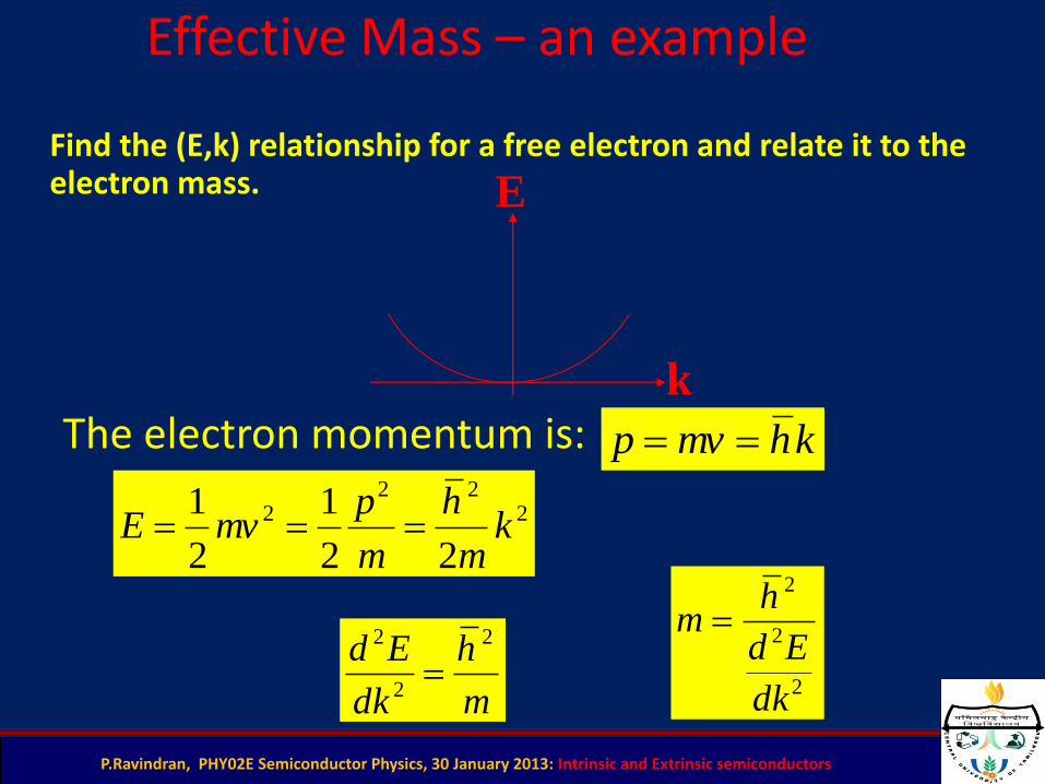
Find the (E,k) relationship for a free electron and relate it to the electron mass.
khmvp
222
2
22
1
2
1k
m
h
m
pmvE
m
h
dk
Ed 2
2
2
E
k
The electron momentum is:
2
2
2
dk
Ed
hm
3
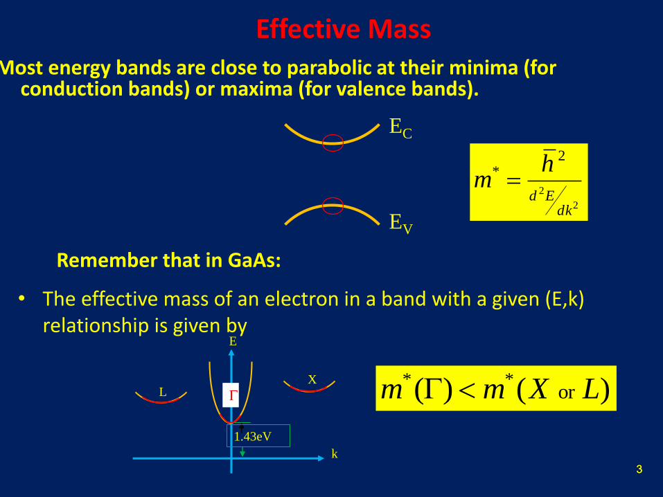
Effective MassMost energy bands are close to parabolic at their minima (for
conduction bands) or maxima (for valence bands).
EC
EV
3
• The effective mass of an electron in a band with a given (E,k) relationship is given by
2
2
2*
dkEd
hm
X
L
k
E
1.43eV
) ()( or** LXmm
Remember that in GaAs:

P.Ravindran, PHY02E Semiconductor Physics, 30 January 2013: Intrinsic and Extrinsic semiconductors
Effective Mass
• At k=0, the (E,k) relationship near the minimum is usually parabolic:
2
2
dk
Ed
2
2
2*
dkij
Eijdij
hm
gEkm
hkE 2
*
2
2)(
In a parabolic band, is constant. So, effective mass is constant.
In most semiconductors the effective mass is a tensor quantity.

Effective Mass
EV
EC
02
2
dk
Ed
02
2
dk
Ed
0* m
0* m2
2
2*
dkEd
hm
Effective mass Ge Si GaAs
† m0 is the free electron rest mass.
Table: Effective mass values for Ge, Si and GaAs.
mn
*
mp
*
055.0 m 01.1 m 0067.0 m
037.0 m 056.0 m 048.0 m

P.Ravindran, PHY02E Semiconductor Physics, 30 January 2013: Intrinsic and Extrinsic semiconductors6
Crystalline structure of Si
• Si N=14 4 bonds, IV-th column of the periodic table
► Diamond lattice, lattice constant a=0.543 nm
► Each atom has 4 nearest neighbor
real 3D
simplified 2D
undoped or intrinsic semiconductor
P.Ravindran, PHY02E Semiconductor Physics, 30 January 2013: Intrinsic and Extrinsic semiconductors
Intrinsic Semiconductor
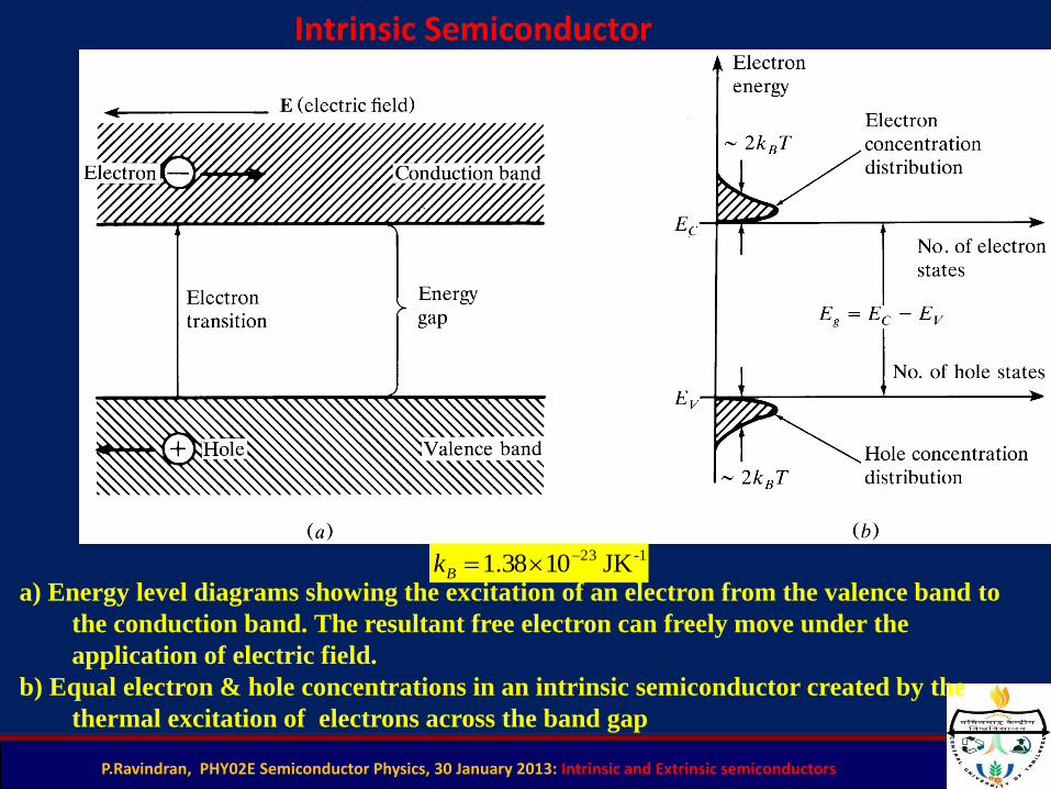
a) Energy level diagrams showing the excitation of an electron from the valence band to
the conduction band. The resultant free electron can freely move under the
application of electric field.
b) Equal electron & hole concentrations in an intrinsic semiconductor created by the
thermal excitation of electrons across the band gap
-123 JK 1038.1 Bk

P.Ravindran, PHY02E Semiconductor Physics, 30 January 2013: Intrinsic and Extrinsic semiconductors
For T > 0K, some VB electrons get enough thermal energy to be excited (through Eg) up to the CB.
Consequently, the semiconductor material will have some electrons in the previously empty CB and some unoccupied states in the previously full VB

P.Ravindran, PHY02E Semiconductor Physics, 30 January 2013: Intrinsic and Extrinsic semiconductors9
Semiconductors: Doping
– When silicon is doped with phosphorous, it becomes a n-type semiconductor, in which an electrical current is carried by negatively charged electrons
– When silicon is doped with boron, it becomes a p-type semiconductor, in which an electrical current is carried by positively charged holes

P.Ravindran, PHY02E Semiconductor Physics, 30 January 2013: Intrinsic and Extrinsic semiconductors
C
V
Eg
Vacancy
Holes
Energy bandModel
BondModel

P.Ravindran, PHY02E Semiconductor Physics, 30 January 2013: Intrinsic and Extrinsic semiconductors
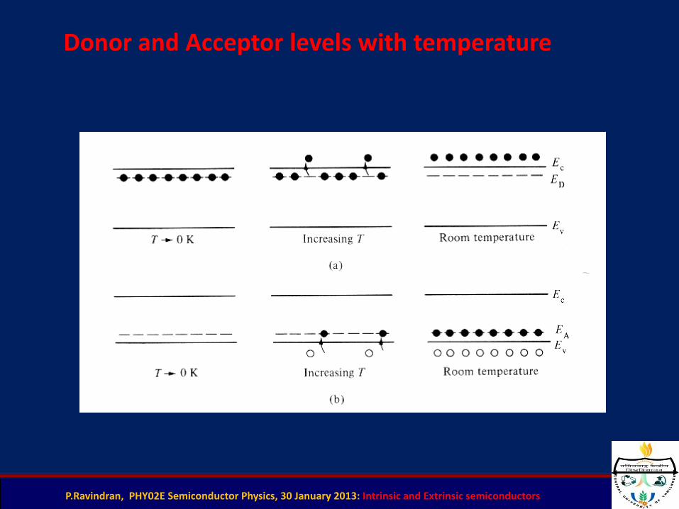
Likewise, acceptor levels can bethermically settled with VBelectrons, by there generatingholes.
Donors and acceptors
At 0K, the donor energy level is filled with electrons and too little thermicalenergy is needed in order to excite these electrons up to the CB. So, between 50-100K, electrons are virtually “donated” to the CB.
P.Ravindran, PHY02E Semiconductor Physics, 30 January 2013: Intrinsic and Extrinsic semiconductors
Donor and Acceptor levels with temperature

P.Ravindran, PHY02E Semiconductor Physics, 30 January 2013: Intrinsic and Extrinsic semiconductors13
Extrinsic Semiconductors (n-type)
Extrinsic semiconductor (p-type)
P.Ravindran, PHY02E Semiconductor Physics, 30 January 2013: Intrinsic and Extrinsic semiconductors
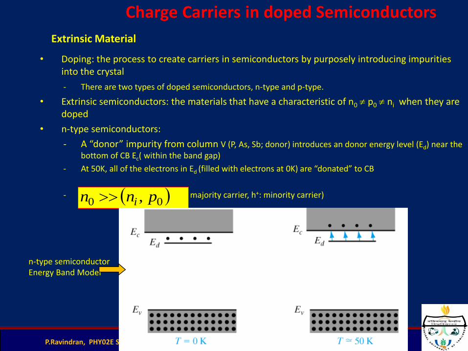
• Doping: the process to create carriers in semiconductors by purposely introducing impurities into the crystal
- There are two types of doped semiconductors, n-type and p-type.
• Extrinsic semiconductors: the materials that have a characteristic of n0 p0 ni when they are doped
• n-type semiconductors:
- A “donor” impurity from column V (P, As, Sb; donor) introduces an donor energy level (Ed) near the bottom of CB Ec( within the band gap)
- At 50K, all of the electrons in Ed (filled with electrons at 0K) are “donated” to CB
- (e-: majority carrier, h+: minority carrier)
Extrinsic Material
00 , pnn i
n-type semiconductor Energy Band Model
Charge Carriers in doped Semiconductors
P.Ravindran, PHY02E Semiconductor Physics, 30 January 2013: Intrinsic and Extrinsic semiconductors
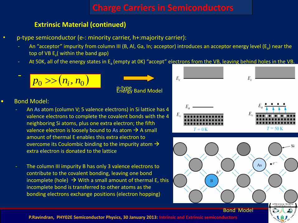
• p-type semiconductor (e-: minority carrier, h+:majority carrier):
- An “acceptor” impurity from column III (B, Al, Ga, In; acceptor) introduces an acceptor energy level (Ea) near the top of VB Ev( within the band gap)
- At 50K, all of the energy states in Ea (empty at 0K) “accept” electrons from the VB, leaving behind holes in the VB.
-
Extrinsic Material (continued)
00 , nnp i
• Bond Model:- An As atom (column V; 5 valence electrons) in Si lattice has 4
valence electrons to complete the covalent bonds with the 4 neighboring Si atoms, plus one extra electron; the fifth valence electron is loosely bound to As atom A small amount of thermal E enables this extra electron to overcome its Coulombic binding to the impurity atom extra electron is donated to the lattice
- The column III impurity B has only 3 valence electrons to contribute to the covalent bonding, leaving one bond incomplete (hole) With a small amount of thermal E, this incomplete bond is transferred to other atoms as the bonding electrons exchange positions (electron hopping)
p-type Energy Band Model
Bond Model
Charge Carriers in Semiconductors
P.Ravindran, PHY02E Semiconductor Physics, 30 January 2013: Intrinsic and Extrinsic semiconductors16
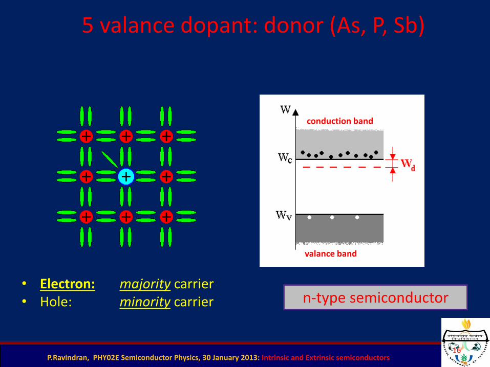
5 valance dopant: donor (As, P, Sb)
• Electron: majority carrier• Hole: minority carrier
conduction band
valance band
n-type semiconductor
P.Ravindran, PHY02E Semiconductor Physics, 30 January 2013: Intrinsic and Extrinsic semiconductors17
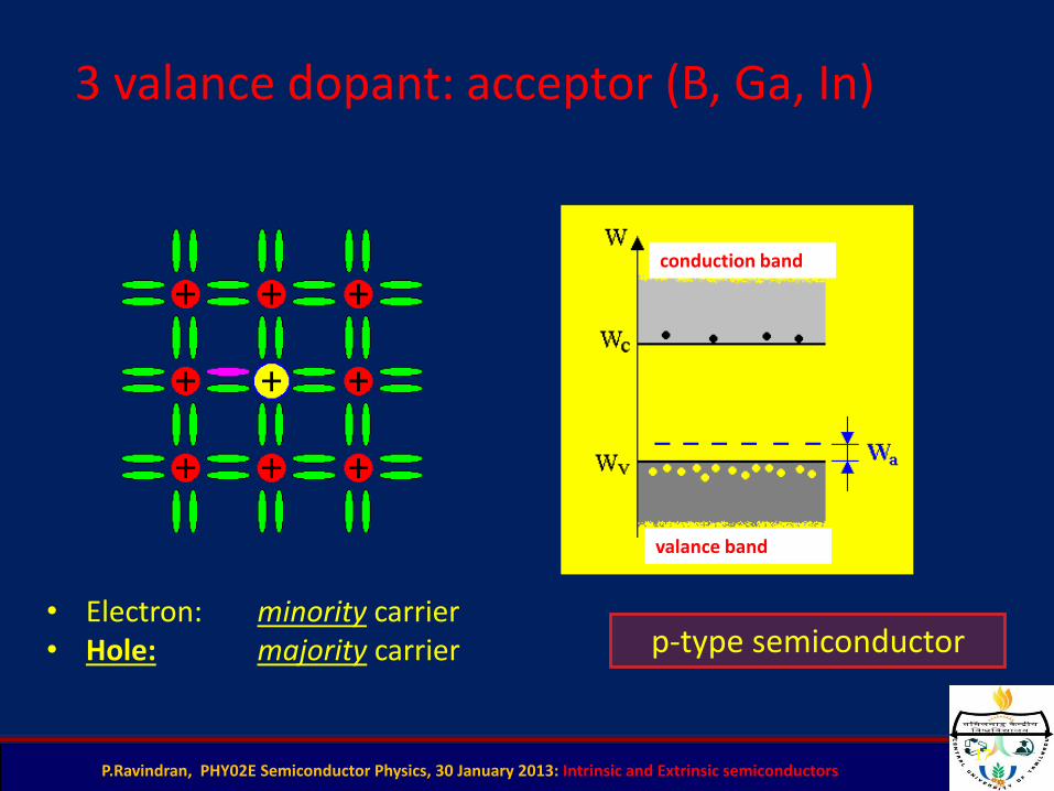
3 valance dopant: acceptor (B, Ga, In)
• Electron: minority carrier• Hole: majority carrier
conduction band
valance band
p-type semiconductor

P.Ravindran, PHY02E Semiconductor Physics, 30 January 2013: Intrinsic and Extrinsic semiconductors
n-Type Semiconductor
a) Donor level in an n-type semiconductor.
b) The ionization of donor impurities creates an increased electron
concentration distribution.
P.Ravindran, PHY02E Semiconductor Physics, 30 January 2013: Intrinsic and Extrinsic semiconductors
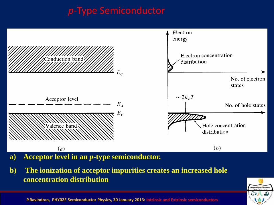
p-Type Semiconductor
a) Acceptor level in an p-type semiconductor.
b) The ionization of acceptor impurities creates an increased hole
concentration distribution

P.Ravindran, PHY02E Semiconductor Physics, 30 January 2013: Intrinsic and Extrinsic semiconductors
Intrinsic & Extrinsic Materials
• Intrinsic material: A perfect material with no impurities.
• Extrinsic material: donor or acceptor type semiconductors.
• Majority carriers: electrons in n-type or holes in p-type.
• Minority carriers: holes in n-type or electrons in p-type.
• The operation of semiconductor devices is essentially based on the injection and extraction of minority carriers.
)2
exp(Tk
Enpn
B
g
i
2
inpn
n,p & ni are the electron, hole, & intrinsic concentrations respectively. Eg is the gap energy, T is temperature.

P.Ravindran, PHY02E Semiconductor Physics, 30 January 2013: Intrinsic and Extrinsic semiconductors21
Calculation of carrier concentration
dWWfWgpvW
v )(1)(0
dWWfWgn
cW
c )()(
possible energy states
occupation probability
concentrations
electrons
holes
FD statistics:
kT
WWWf
Fexp1
1)(
P.Ravindran, PHY02E Semiconductor Physics, 30 January 2013: Intrinsic and Extrinsic semiconductors
T
TETE gg
2
)0()(
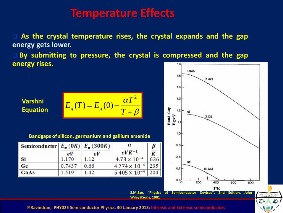
As the crystal temperature rises, the crystal expands and the gapenergy gets lower.
By submitting to pressure, the crystal is compressed and the gapenergy rises.
Varshni Equation
Temperature Effects
S.M.Sze, “Physics of Semiconductor Devices”, 2nd Edition, JohnWiley&Sons, 1981
Bandgaps of silicon, germanium and gallium arsenide

P.Ravindran, PHY02E Semiconductor Physics, 30 January 2013: Intrinsic and Extrinsic semiconductors
Intrinsic Semiconductor
Extrinsic Semiconductor
Donor impurities – provide extra electrons to conduction(type n)
Acceptor impurities – provide exceedingholes to conduction(type p)
inpn
Doping of SemiconductorsDoping of Semiconductors
• We can estimate the BINDING ENERGY of the surplus electron or hole provided by each
dopant in a rather simple way
* In the case where the dopant is a DONOR the loosely-bound additional electron orbits
a core with a net POSITIVE charge
The donor is thus essentially similar to a HYDROGEN ATOM and the binding
energy of the surplus electron can be computed from the expression for the
IONIZATION ENERGY of the hydrogen atom
)2.34(eV1.0)(8 22
4*
h
em
or
e
• THE IONIZATION ENERGY OF A HYDROGEN ATOM IS GIVEN AS
(SUBJECT_14)
• FOR A DONOR ELECTRON IN SILICON THIS EXPRESSION IS MODIFIED
BY INCLUDING THE EFFECTIVE ELECTRON MASS (me* = 1.18 mo) AND
THE DIELECTRIC CONSTANT (r = 11.8) IN SILICON
)1.34(eV6.138 22
4
h
me
o
A GROUP V DOPANT IN A SILICON LATTICE
CAN BE VIEWED AS A PSEUDO HYDROGEN ATOM!
e-
+
Doping of Semiconductors
• A similar argument to that above may also be made for an ACCEPTOR in silicon but now
the pseudo hydrogen atom consists of a POSITIVE HOLE that orbits a NEGATIVE core
* This gives a SIMILAR estimate for the binding energy of the HOLE
* The ACTUAL donor and acceptor binding energies measured in experiment agree
reasonably WELL with these SIMPLE estimates
• A GROUP III DOPANT IN A SILICON LATTICE CAN ALSO
BE VIEWED AS A PSEUDO HYDROGEN ATOM
• IN THIS CASE HOWEVER THE DOPANT CORE APPEARS
NEGATIVELY CHARGED AND IS ORBITED BY A HOLE
P As Sb B Al Ga In
Si .045 .049 .039 .045 .057 .065 .016
Ge .012 .013 .010 .010 .010 .011 .011
BINDING ENERGY FOR DONORS (eV) BINDING ENERGY FOR ACCEPTORS (eV)
B
e+
B
e+
Si:As
Si:B

P.Ravindran, PHY02E Semiconductor Physics, 30 January 2013: Intrinsic and Extrinsic semiconductors
Concept of Fermi-Dirac distribution function
Distribution of electrons over a range of allowed energy levels at thermal equilibrium is given by :
f(E) = 1
1 + e(E – EF) / kT
K – Boltzman’s constant = 8.62 x 10⁻⁵ eV / K= 1.38 x 10 -23 J / K
f(E) gives the probability of findiing a electron in a particular energy E.