effective may 2011 instructional booklet …...5 instructional booklet ib02102006e effective may...
TRANSCRIPT

Description Page
Introduction . . . . . . . . . . . . . . . . . . . . . . . . . . . . . 2Receiving, handling, and storage . . . . . . . . . . . . 4Installation . . . . . . . . . . . . . . . . . . . . . . . . . . . . . . 5Operation . . . . . . . . . . . . . . . . . . . . . . . . . . . . . . 16Maintenance . . . . . . . . . . . . . . . . . . . . . . . . . . . 17Duplex switchgear configuration . . . . . . . . . . . . 23Motor operation . . . . . . . . . . . . . . . . . . . . . . . . . 23Electromechanical stored energy release (shunt trip) . . . . . . . . . . . . . . . . . . . . . . . . . . 25MVS switchgear bolt tightness for bus connections and connections to switch terminal pads . . . . . . . . . . . . . . . . . . 28Common renewal parts . . . . . . . . . . . . . . . . . . . 28
Effective May 2011Supersedes April 2006Instructional Booklet IB02102006E
Type MVS (previously WLI)metal-enclosed switchgear—4.76 kV, 15.0 kV, 27.0 kV, and 38.0 kV

2
Instructional Booklet IB02102006EEffective May 2011
Type MVS (previously WLI)metal-enclosed switchgear—
4.76 kV, 15.0 kV, 27.0 kV, and 38.0 kV
eaton corporation www.eaton.com
introductionRead and understand these instructions before attempting any installation, operation, or maintenance of this switchgear .
Purpose
This instruction book is expressly intended to cover the installation, operation, and maintenance of type Medium Voltage Switch (MVS), previously known as the Westinghouse Load Interrupter (WLI) metal-enclosed switchgear . It does not purport to cover all possible contingencies, variations, and details that may arise during installation, operation, or maintenance of this equipment .
If further information is desired by the purchaser regarding this particular installation or application information, contact the local Eaton sales office, see Eaton’s Consulting Application Guide, and review the appropriate industry standards .
Basic description and application
A type MVS (previously WLI) metal-enclosed switchgear assembly vertical section consists of an air insulated, three-pole, gang- operated, quick-make, quick-break, load interrupter switch in a floor-mounted metal enclosure . It can be applied in combination with power fuses and many other protective devices to provide safe, economical switching and circuit protection where infrequent disconnecting means is required .
Switchgear identification
A nameplate is located inside the small access door of each type MVS switchgear vertical section (see Figure 1) . Contained on this nameplate are the Eaton master parts list number and all the necessary switchgear ratings . This information should be given to the Eaton sales office if a question should arise concerning the switchgear or if renewal parts are required . This information is sufficient for Eaton to find the manufacturing information for the switchgear .
The switch rating nameplate is on the switch mechanism cover . This nameplate is readily visible when the main enclosure door is opened . This nameplate contains all of the switch’s ratings and style number .
Figure 1. Typical Nameplate
1A33788H01
symmetrical amperes; volts maximum.
ratings when fuses are mounted in this vertical section.
See separate label inside for fuse continuous current
capable of delivering not more than RMS
This switchgear vertical section is suitable for use on a circuit
of industry standards IEEE C37.20.3 and ANSI C37.57
Type Switchgear Assemblies meet the requirements
Short Time (2 Sec., Sym)
Momentary RMS Asym
Continuous:
Maximum Continuous
Master P.L.:
GO & It:
Section No. Of
Date:
3 Phase 60 Hz.
kV BIL:Operating Volts:
Mfd. At:
Encl. Category:
Enclosure Type:
Type:
Instructions
Medium Voltage Metal Enclosed Switchgear Assembly
Main Cross Bus Current Ratings

3
Instructional Booklet IB02102006EEffective May 2011
Type MVS (previously WLI)metal-enclosed switchgear—4.76 kV, 15.0 kV, 27.0 kV, and 38.0 kV
eaton corporation www.eaton.com
Figure 2. Switch Nameplate
Maximum
3 Phase 60 Hz
Fault Close and Momentary,
Continuous and Load Break
Asymmetrical
(2 seconds)
Replacement fuses shall be ofthe same manufacture, type,and interrupting rating.
IEEE C37.20.4 ANSI C37.58
Instructions
Mfd At:
Fuse Type
Short-Time
BIL
1A33788H02
ANSI C37.22
Style
Date
Type
Fused Fault Close,
Asymmetrical
Load Interrupter Switch
Current Ratings, A
Industry Standards
Voltage Ratings, kV
�
Safety features
Type MVS load interrupter switchgear has several built-in features to reduce hazards and to provide proper operating sequences .
WARNINGEXCEEDING THE NAMEPLATE RATINGS OF MVS SWITCHGEAR MAy CAUSE PROPERTy DAMAGE, SEVERE INJURy, OR DEATH. MVS SWITCHGEAR MUST BE OPERATED WITHIN ITS NAME-PLATED RATINGS.
1. A door interlock prevents opening the enclosure front door while the switch is in the “Closed” position .
2. A switch interlock prevents manual operation of the handle mechanism with the door open .
3. A viewing window is provided to visually verify the switch contact position .
4. Facility is provided for padlocking the switch in the “Open” or “Closed” position .
5. Facilities are provided for padlocking the door handles closed .
6. Mechanical indicators show whether the switch mechanism is “Open” or “Closed .”
7. Key interlocks, when provided, force a sequence of operation .
CAUTIONOPERATING AN MVS SWITCH WITH A KEy INTERLOCK BOLT EXTENDED WILL RESULT IN EQUIPMENT DAMAGE AND MAy ALSO EXPOSE THE OPERATOR TO BODILy INJURy OR DEATH. THE KEy MUST BE INSERTED INTO THE INTERLOCK AND ROTATED TO RETRACT THE LOCKING BOLT BEFORE OPERATING AN MVS SWITCH.
Safety practices
Only qualified electrical workers with training and experience on high voltage circuits should be permitted to work on this equipment . They should be familiar with the work to be performed, the safety equipment required, and the hazards involved .
1. Read and fully understand these instructions before attempting any assembly, operation, or maintenance of this switchgear .
WARNINGEXCEEDING THE NAMEPLATE RATINGS OF MVS SWITCHGEAR MAy CAUSE PROPERTy DAMAGE, SEVERE INJURy, OR DEATH. MVS SWITCHGEAR MUST BE OPERATED WITHIN ITS NAME-PLATED RATINGS.
2. Disconnect all power sources before making any adjustments or performing maintenance .
3. After opening the switch and before opening the door, use the viewing window to ensure that all three switch blades are open . If necessary, use a flashlight to verify that all three contacts are open .

4
Instructional Booklet IB02102006EEffective May 2011
Type MVS (previously WLI)metal-enclosed switchgear—
4.76 kV, 15.0 kV, 27.0 kV, and 38.0 kV
eaton corporation www.eaton.com
WARNINGTHERE ARE SEVERAL INTERLOCKS ON THE SWITCHES. THEy ARE FOR PERSONNEL AND/OR EQUIPMENT PROTECTION. UNDER NO CIRCUMSTANCES SHOULD THEy BE MADE INOPERATIVE WHEN SWITCH IS IN SERVICE. TO DO SO MAy CAUSE BODILy INJURy OR PROPERTy DAMAGE.
4. Never energize the switch without the arc chutes and the barriers installed .
5. Always be sure that all hardware is in place and bolted tightly before putting the switch into operation .
6. Before replacing covers, carefully inspect the bus work and phase barriers to ensure that no tools or other objects are accidentally left inside the unit .
Revision
Effective May 2011 . Supersedes IB02102006E dated April, 2006 .
Eaton contact information
For the location of the nearest Eaton sales office or distributor, call toll-free 1-800-525-2000 or log onto www .eaton .com .
receiving, handling, and storageReceiving
A visual inspection—inside and out—should be performed immediately upon receipt of the switchgear and before removing it from the truck . Shipping papers should be checked to be sure that all boxes or other accompanying pieces have been received . If any damage or shortages are evident, a claim should be filed at once with the carrier and the nearest Eaton office notified .
The data nameplate for each switchgear assembly is located inside the mechanism access door . The master parts list number is located on this nameplate and should be given to the Eaton representative whenever identification of the assembly is required .
Handling
Removable lifting lugs are provided on the top of the MVS structure for insertion of hooks to lift the complete structure . This is the only recommended method of moving the MVS structure .
CAUTIONEXTREME CARE SHOULD BE USED NOT TO DAMAGE OR DEFORM THE SWITCHGEAR IF OTHER MOVING METHODS ARE EMPLOyED.
Storage
If it is necessary to store the equipment before installation, keep it in a clean, dry location with ample air circulation and heat to prevent condensation . Like all electrical apparatus, these units contain insulation that must be protected against dirt and moisture .
otee:N Outdoor units may be stored outside ONLY if the roof caps are installed, the space heaters are energized, and any openings are enclosed .

5
Instructional Booklet IB02102006EEffective May 2011
Type MVS (previously WLI)metal-enclosed switchgear—4.76 kV, 15.0 kV, 27.0 kV, and 38.0 kV
eaton corporation www.eaton.com
installationRefer to the shipping list for the location of bus, hardware, and all other joining and installation material .
Joining type MVS enclosures
Access to MVS switch vertical sections containing switches
Each MVS switch is shipped from the factory in the “Closed” posi-tion to maintain alignment during shipping and handling . The safety interlocking prevents opening of the door of the vertical section when the switch is closed . In order to gain access to the interior, be sure that the switchgear is on a true and level surface . To open a manually operated MVS switch, insert the operating handle and push down . When the switch opens, the door may be opened . If the switch is equipped with an electromechanical stored energy release feature, follow the instructions on the instruction label located inside the mechanism access door . If the switch is motor operated, it will function identically to a manually operated switch .
When handling MVS switchgear, be sure that the switches are in the “Closed” position . Do not operate MVS switches unless they are setting on true and level surfaces . The definition of level is the foundation cannot deviate more than ± 0 .0125 inches in 36 .00 inches (0 .318 mm in 914 .4 mm) front to rear, left to right, and diagonally at any point beneath the switchgear .
Identification of shipping splits
Refer to the front view drawing . Below this drawing, shipping splits will be identified in relation to group numbers for each vertical section . Normally, shipping sections will not exceed 154 .00 inches (3911 .6 mm) in width .
Procedures for joining MVS enclosures at shipping splits
Refer to Figure 3 while completing the following procedure .
Step 1e: Remove the eight 0 .375–16 inch bolts from each side sheet .
Step 2e: Position the shipping sections next to each other . The eight holes will usually match the holes in the adjacent side sheets but, in some cases, it may be necessary to use an aligning tool such as a punch to force the structures into alignment .
Step 3e: Bolt the side sheets together using the eight bolts removed from one side sheet in Step 1 .
Figure 3. Joining MVS Enclosures
Step 4e: Make the main and ground bus connections using splice plates and the hardware furnished . The busbar is tin- or silver-plated . To ensure a proper electrical connection, care should be taken to protect the plating from damage . DO NOT use joint compound .
Cutout
MountingBolts
Vertical Section to Left Vertical Section to Right
L ofBusbarC
CAUTIONCLEANING BUS JOINTS WITH ABRASIVE OR CHEMICAL CLEANSERS MAy REMOVE PLATING. THIS COULD RESULT IN JOINT OVERHEATING. WIPE THE BUS JOINTS WITH A CLEAN, DRy CLOTH TO CLEAN SURFACES.
Step 5e: Bolted connections should be tightened to the torque values given on page 28 .
Installation of roof caps on outdoor units
Roof caps are necessary to complete the roof on all outdoor MVS switchgear assemblies . Those not factory installed are shipped in cartons that may be put within one or more of the vertical sections if there is space, or they will be shipped separately .
Roofs requiring sealing compound
The following procedure details the work to be done to install each cap on a caulking compound sealed roof joint .
Step 1e: Remove the bolts securing the lifting lugs to the MVS assembly . Remove the lifting lugs then replace the bolts just removed .
Step 2e: Place a roof cap in position and start enough screws (provided loose in a hardware package) to temporarily hold it in place
Step 3e: Draw a pencil line down the side(s) on to the roof to mark the edge(s) of the cap on the roof .
Step 4e: Remove roof cap and apply a 0 .25 inch (6 .35 mm) bead of caulking (provided by Eaton with the switch) along the inside edge of the pencil line(s) .
Step 5e: Hold the edge of the roof cap adjacent to the pencil line, then rotate it over onto the bead(s) of caulk, aligning it with the bolt holes in the roof as the action is completed .
Step 6e: Install the supplied bolts and gasketed washers (rubber side toward roof cap) in every bolt hole of roof cap . Tighten the bolts to 5 ft-lbs (6 .78 Nm) .
Figure 4. Roof Cap Installation
Step 7e: Following instructions on the caulking container, smooth out any excess caulk along the edges of the roof cap .
Step 8e: Repeat this procedure until all roof caps have been installed .
For roofs that have edges turned up and formed caps to cover the edges, it is only necessary to place the appropriate caps over the roof edges and fasten them in place with the appropriate fasteners .
.

6
Instructional Booklet IB02102006EEffective May 2011
Type MVS (previously WLI)metal-enclosed switchgear—
4.76 kV, 15.0 kV, 27.0 kV, and 38.0 kV
eaton corporation www.eaton.com
Connection to type MVS switchgear to a transformer
Physical connection
Indoor assemblies, dry-type, cast coil type, or liquid- filled type transformers
Holes are predrilled in the side of the MVS structure to match the holes provided in the transformer .
Outdoor throat connection, liquid-filled transformers
Refer to Figure 5 while completing the following procedure .
Step 1e: Remove the sealing ring flange from the MVS switchgear throat and set it aside .
Step 2e: The switch and the transformer should be brought together to provide spacing of approximately 0 .50 inches (12 .7 mm) between the throat flanges .
Step 3e: Apply the double-faced adhesive tape supplied with the MVS switchgear to the outside surfaces of both flanges .
Step 4e: Press the felt supplied with the MVS switchgear into place on the adhesive tape . The felt is to seal against the entrance of dust and to prevent transmission of the vibration produced by transformer resonance to the MVS switchgear .
Step 5e: Reinstall the sealing ring removed in Step 1 .
Figure 5. Transformer Connection to the MVS Switch
Medium voltage electrical connections
Connection by cable supplied with the type MVS switch
• Cables are NOT factory pre-cut to the proper length . The installer MUST cut them to fit .
• Factory cables are unshielded . For 15 kV, 27kV, and 38 kV applications, they must be properly separated from each other, from all grounded metal parts, and from the transformer bushings/terminals of other phases . For 4 .76 kV applications, it is only necessary to install the cables so they will not be damaged by sharp edges, points, etc .
• Phasing of the main conductors in type MVS switchgear conforms to industry standards: that is 1, 2, 3, front to rear, top to bottom, and left to right at the connection points unless otherwise noted on the drawings . The installer is responsible for maintaining the continuity of phasing throughout the system .
• Lugs are provided with the switchgear for terminating cables to the transformer bushings/terminals .
Connection by busbar
• Splice plates and hardware are provided with the MVS switchgear . The transformer manufacturer supplies the flexible connector .
• The busbar is tin- or silver-plated . To ensure a proper electrical connection, care should be taken to protect the plating from damage . Refer to “Procedures for joining MVS enclosures at shipping splits” section on page 5 for details .
Connections to an AMPGARDT medium voltage motor control center (MCC)
Step 1: Holes are predrilled in the side of the MVS switchgear structure to match the holes provided in the AMPGARD MCC . Bolt the MVS switchgear and AMPGARD MCC together using the hardware furnished with the MVS switchgear .
Step 2: Make the bus connections as per “Connections by busbar” section above .

7
Instructional Booklet IB02102006EEffective May 2011
Type MVS (previously WLI)metal-enclosed switchgear—4.76 kV, 15.0 kV, 27.0 kV, and 38.0 kV
eaton corporation www.eaton.com
Connections to a medium voltage assembly (MVA) metal-clad switchgear assembly
Indoor switchgear
Follow the same procedures outlined in “Connections to an AMPGARD medium voltage MCC” section above .
Outdoor switchgear
Step 1e: Position the units side by side . The holes in the MVS side sheet around the bus cutout will match the holes in the metal-clad switchgear flange .
Step 2e: Press the sponge neoprene gasketing tape, supplied with the MVS switchgear, onto the flange for the weather-tight seal .
Step 3e: Join the enclosures using the bolts supplied with the MVS . The opposite side of the metal-clad switchgear flange has nuts welded in place for ease of connection .
Step 4e: Make the bus connections as per “Connection by busbar” section above .
Connection of customer power cables
Figure 6 through Figure 15 show the suggested means for connec-tion of the incoming or exiting cables (maximum of two per phase, 500 kcmil) to the MVS switchgear . The letters in each figure apply to the itemized subjects (A through E) that follow . All necessary materials to perform the cable installation are to be provided by others unless specifically noted otherwise in the detailed instruc-tions or where specifically purchased with the switchgear assembly . To install the incoming and exiting cables, follow these instructions .
A. The switchgear terminals—For incoming power, the terminals are usually located at the top of the switch in a vertical section . For outgoing circuits, the terminals are beneath the switch if unfused, or on the fuse mounting if fused . Each terminal pad has a two-hole pattern suitable for either a single hole terminal or a terminal with a two-hole National Electrical Manufacturers Association (NEMAT) drilling pattern . The terminal lugs for the cable, if purchased with the switchgear, will be bolted to the switchgear terminals . If the terminal lugs are not there, then they are to be provided by others . The terminals of the switch-gear are not suitable to support the weight of the cable . It will be necessary to support the weight of the cable with the cable support angle discussed in C below .
B. Cable electrical stress relief devices—The design of MVS switchgear is based upon use of “pre-formed” type electrical stress relief devices such as 3-M Quickterm-IIT, RaychemT heat shrink termination systems, etc . The stress relief devices are to be provided by others .
C. Cable support channel(s)—The cable support channel(s) is not supplied by Eaton unless purchased as a feature at the time of offer . The cable supports may be mounted to suit the geometry of the installation by drilling holes in the switchgear structure to suit . The tamper-resistant hardware provided is to anchor the support channel(s) to the structure . Use the regular hardware to fasten the channel(s) to the mounting clips . The means to fasten the cable to this channel(s) is to be provided by others . There are a large number of commercially available cable support devices that can be fastened to this channel(s) to support the cable so that the cable weight is not hanging on the switchgear terminals .
WARNINGFAILURE TO INSTALL THE CABLE SUPPORT MAy RESULT IN DAMAGE TO THE SWITCHGEAR TERMINALS, WHICH IN TURN MAy RESULT IN MAJOR EQUIPMENT DAMAGE AND CAUSE SEVERE PERSONAL INJURy OR DEATH. THE CABLE SUPPORT MUST BE INSTALLED AS INSTRUCTED IN THIS DOCUMENT.
D. Lacing cord or other equivalent materials/means—The cables must be lashed together to restrain the cables if a short circuit should occur . This material is to be provided by others . For large cables and/or cable reverse loops, it may also be necessary to lash the cable bundle(s) to the support channel . The views show this suggested fastening of the cable bundles .
WARNINGFAILURE TO LASH THE CABLES TOGETHER MAy RESULT IN DAMAGE TO THE SWITCHGEAR, WHICH IN TURN MAy RESULT IN MAJOR EQUIPMENT DAMAGE AND CAUSE SEVERE PERSONAL INJURy OR DEATH. THE CABLE MUST BE LASHED TOGETHER AS INSTRUCTED IN THIS DOCUMENT
E. Current transformer(s)—The current transformer(s) is to be mounted on the side of the cable support that will physically support the current transformer(s) so it will not slide down onto the stress relief devices . The high voltage cable is to be routed through the current transformer . The H1 side of each current transformer is to be toward the normal source of electric power . Each current transformer secondary wiring is terminated at a plug . This plug is to be placed in the terminal block receptacle to match the phase on which the current transformer is mounted . The switchgear terminals will have phase labeling . The secondary wires are to be fastened to the support channel so they can not fall into high voltage parts .

8
Instructional Booklet IB02102006EEffective May 2011
Type MVS (previously WLI)metal-enclosed switchgear—
4.76 kV, 15.0 kV, 27.0 kV, and 38.0 kV
eaton corporation www.eaton.com
Figure 6. Bottom Cable Entrance (Energy Source), Rear Access
Figure 7. Top Cable Entrance (Energy Source), Rear Access
Figure 8. Unfused Bottom Cable Exit (to Load), Rear Access
Figure 9. Unfused Top Cable Exit (to Load), Rear Access

9
Instructional Booklet IB02102006EEffective May 2011
Type MVS (previously WLI)metal-enclosed switchgear—4.76 kV, 15.0 kV, 27.0 kV, and 38.0 kV
eaton corporation www.eaton.com
Figure 10. Top Cable Entrance (Energy Source), Front Access
Figure 11. Bottom Cable Entrance (Energy Source), Front Access

10
Instructional Booklet IB02102006EEffective May 2011
Type MVS (previously WLI)metal-enclosed switchgear—
4.76 kV, 15.0 kV, 27.0 kV, and 38.0 kV
eaton corporation www.eaton.com
Figure 12. Unfused Top Cable Exit (to Load), Front Access
Figure 13. Unfused Bottom Cable Exit (to Load), Front Access
Figure 14. Fused Top Cable Exit (to Load), Front Access
Figure 15. Fused Bottom Cable Exit (to Load), Front Access

11
Instructional Booklet IB02102006EEffective May 2011
Type MVS (previously WLI)metal-enclosed switchgear—4.76 kV, 15.0 kV, 27.0 kV, and 38.0 kV
eaton corporation www.eaton.com
Field taping of electrical connections
During the following procedures, please refer to Figure 16 .
Figure 16. Field Taping of Electrical Connections
Definitions and Eaton approved materials for field insulation
Fillere: Nashua No . 102 Duct SealerT or 3M Co . ScotchfilT or NeerT Duct Seal .
Insulating tape and pade: Either 3M Co . Scotch 23T or Scotch 130CT .
Insulating boote: Molded plastic cover that is put over a joint and fastened in place with wire ties .
Jointe: An area to be insulated . This consists of the bare conductor and 1 .50 inches (38 .1 mm) of any pre-insulation next to the bare conductor .
Layere: Insulating tape, 1 .00-inch (25 .4 mm) wide, wrapped from one end of the joint to the other (or to a pad) so that each succeeding turn laps the previous turn by the amount specified in the taping chart .
Overlape: A specified distance measured along the pre-insulation starting from the point where the pre-insulation ends and where the exposed conductor begins .
Pade: Any insulating tape applied that is wider than 1 .00 inch (25 .4 mm) . Includes a band of tape consisting of one or more turns wrapped directly on top of each other .
Pre-insulatione: Any insulation covering (sleeving materials such as NORYLT, RaychemT, ScotchititeT, and fluidized epoxy coating) adjacent to an exposed conductor prior to insulating .
WARNINGTHE USE OF SOLVENTS, OILS, JOINT COMPOUNDS, OR GREASE ON OR NEAR NORyL INSULATION WILL DESTROy IT.
1-1/2" (Minimum Lap)
Filler
Pre-Insulation
Typical Insulating Tape and Pad
InsulatingTape
PadLap
Responsibility of installer
• For incoming or outgoing terminations, these approved materials are not supplied by Eaton and must be obtained and installed by others as identified in the definitions on this page .
• For connections involving shipping splits within an MVS switchgear assembly, or connecting to a transformer, or to an AMPGARD MCC, or to an MVA switchgear assembly, or to a medium voltage bus run, insulating materials will be supplied if necessary by Eaton It is the responsibility of the installer to insulate the connections in accordance with these instructions
• For a switchgear assembly that does not have continuous insulating sleeving on the phase bus conductors and where the dimensions in Table 1 are not met at field assembled connections, insulation of these connections must be made
Table 1. Minimum Clearance Chart
kV rating of the MVS Switchgear
phase-to-phase a inches (mm)
phase-to-Ground inches (mm)
4.76 3.50 (88.9) 3.50 (88.9)15 6.00 (152.4) 6.00 (152.4)27 8.00 (203.2) 8.00 (203.2)38 10.50 (266.7) 10.50 (266.7)
a If the phase-to-phase clearances above for a given rating do not exist, then it is only necessary to insulate the center phase.
CAUTIONFAILURE TO INSTALL FIELD INSULATION WHERE NECESSARy IN ACCORDANCE WITH THESE INSTRUCTIONS WILL COMPROMISE THE ELECTRICAL RATINGS OF THE SWITCHGEAR ASSEMBLy. INSTALL FIELD INSULATION TO MAINTAIN THE ELECTRICAL RATINGS.

12
Instructional Booklet IB02102006EEffective May 2011
Type MVS (previously WLI)metal-enclosed switchgear—
4.76 kV, 15.0 kV, 27.0 kV, and 38.0 kV
eaton corporation www.eaton.com
Field insulation methods
Method 1—using an insulating boot
Step 1e: Clean the area of dirt and foreign matter . Use a clean, dry cloth or, if necessary, dampen slightly with distilled water . Do not use any abrasives or solvents .
Step 2e: Place the boot over the joint so that it fits in place . Fasten together with plastic wire ties . Cut off excess ends of plastic wire ties .
Method 2—using insulating tape and filler
General
Step 1e: Elongate the insulating tape 10 to 25% during application to ensure a smooth, tight fit . On pads, elongate the corners only .
Step 2e: Should a tape roll expire during application, start the new role by overlapping the previous end by 1/2 turn .
Joint—no hardware
Step 1e: Clean the area of dirt and foreign matter . Use a clean, dry cloth or, if necessary, dampen slightly with distilled water . Do not use any abrasives or solvents .
Step 2e: Apply one turn of 1 .00 inch (25 .4 mm) tape so that half of the tape is on the conductor and half is on the pre-insulation . Overlap the tape ends 1 .50 inches (38 .1 mm) .
Step 3e: Apply one layer of insulating tape, lapping as specified in Table 2, overlapping any pre-insulation by 1 .50 inches (38 .1 mm) .
Joint—with hardware
Step 1e: Clean the area of dirt and foreign matter . Use a clean, dry cloth or, if necessary, dampen slightly with distilled water . Do not use any abrasives or solvents .
Step 2e: Apply the filler over the bare conductor and hardware to cover and to smooth out the surface . Blend the contour into pre- insulation surfaces . Cover the conductors and hardware with at least 0 .125 inches (3 .18 mm) of filler .
Step 3e: Apply pad(s) of insulating tape of sufficient width to overlap the pre-insulation by 1 .00 inch (25 .4 mm) or more .
Step 4e: Apply one layer of insulating tape, lapping as specified in Table 2, overlapping any pre-insulation or pads by 1 .50 inches (38 .1 mm) .
Factory-installed Noryl insulation
Factory-installed insulation may be Noryl, a high-performance engineering thermoplastic . It can be irreversibly damaged if it comes in contact with certain chemicals . See page 22 for cleaning procedures .
WARNINGTHE USE OF SOLVENTS, OILS, JOINT COMPOUNDS, OR GREASES ON OR NEAR NORyL INSULATION WILL DESTROy IT. CLEAN ONLy WITH WATER OR ISOPROPyL ALCOHOL.
CAUTIONISOPROPyL ALCOHOL IS FLAMMABLE. PROVIDE ADEQUATE VENTILATION AND KEEP AWAy FROM FLAMES AND OTHER IGNITION SOURCES. CONSULT yOUR SAFETy DEPARTMENT BEFORE USING.
Securing MVS switchgear assemblies to foundations
All anchoring hardware and necessary devices are to be supplied by the installer . If the switchgear assembly was purchased for seismic applications, follow the instructions on special drawings provided addressing the anchoring and load bearing requirements in additions to the following two sections .
Table 2. Taping Chart
MVS kV rating
pre-insulation or pad overlap (Minimum)inches (mm) Lap of tape
insulating tapenumber of Layers number of pads
4.76 1.50 (38.1) 1/2 1 1Over 4.76 1.50 (38.1) 2/3 2 2

13
Instructional Booklet IB02102006EEffective May 2011
Type MVS (previously WLI)metal-enclosed switchgear—4.76 kV, 15.0 kV, 27.0 kV, and 38.0 kV
eaton corporation www.eaton.com
Typical floor plans
Figure 17 and Figure 18 show floor plans for installing MVS switch-gear in typical and seismic applications .
Figure 17. Floor Plan of a Typical Non-Seismic MVS 4.76 kV or 15 kV Switchgear Vertical Section
Width2
Locations for tie-down clips, provisionsfor 0.50 inch (13 mm) anchor bolts.
Door swing equals unit width at 90º degrees.
Minimum clearance on side. Local jurisdictionsmay require a larger clearance.
Minimum clearance in front is the width of the widest vertical section plus 1.00 inch (25.4 mm). Local jurisdictions may require a larger distance.
Minimum clearance in rear, local jurisdictionsmay require a larger distance.
The foundation’s surface shall be level within± 0.0125 inch in 36.00 inches (0.318 mm in 914.4 mm)Left to right, front to rear, and diagonally, as measured by a laser level at any point beneath the switchgear assembly.
�
�
�
�
�
�
�
�
�
�
�
�
.44(11.0)Type
6.00(152.0)
Minimum
.86(22.0)Type
1.37(35.0)Type
1.00(25.0)
Minimum
Minimum
FrontDoor
30.00(762.0)
Minimum
Figure 18. Floor Plan of a Typical Seismic MVS 4.76 kV or 15 kV Switchgear Vertical Section
Locations for tie-down clips, provisionsfor 0.50 inch (13.0 mm) anchor bolts.
Door swing equals unit width at 90º degrees.
Minimum clearance on side. Local jurisdictionsmay require a larger clearance.
Minimum clearance in front is the width of the widest vertical section plus 1.00 inch (25.4 mm). Local jurisdictions may require a larger distance.
Minimum clearance in rear, local jurisdictionsmay require a larger distance.
The foundation’s surface shall be level within± 0.0125 inch in 36.00 inches (0.318 mm in 914.4 mm)Left to right, front to rear, and diagonally, as measured by a laser level at any point beneath the switchgear assembly.
�
�
�
�
�
�
�
�
�
�
�
�
.44(11.0)Type
6.00(152.0)
Minimum
.86(22.0)Type
1.37(35.0)Type
1.00(25.0)
Minimum
Minimum
FrontDoor
30.00(762.0)
Minimum
4.50(114.0)Type

14
Instructional Booklet IB02102006EEffective May 2011
Type MVS (previously WLI)metal-enclosed switchgear—
4.76 kV, 15.0 kV, 27.0 kV, and 38.0 kV
eaton corporation www.eaton.com
Indoor installations
Indoor vertical sections may be secured to the foundation using 0 .50 inch (12 .7 mm) anchor bolts . The four 0 .625 inch (15 .88 mm) holes in the base for these bolts are shown on the floor plan included with the drawings .
Figure 19 shows the floor plan for typical indoor MVS switchgear installations .
Figure 19. Floor Plan of a Typical Indoor MVS 27 kV or 38 kV Vertical Section, Non-Seismic or Seismic
Locations for 0.50 inch (13.0 mm) anchor bolts.
Door swing equals unit width at 90º degrees.
Minimum clearance on side. Local jurisdictionsmay require a larger clearance.
Minimum clearance in front is the width of the widest vertical section plus 1.00 inch (25.4 mm). Local jurisdictions may require a larger distance.
Minimum clearance in rear, local jurisdictionsmay require a larger distance.
The foundation’s surface shall be level within± 0.0125 inch in 36.00 inches (0.318 mm in 914.4 mm)Left to right, front to rear, and diagonally, as measured by a laser level at any point beneath the switchgear assembly.
�
�
�
�
�
�
�
�
�
�
�
�
5.81(148.0)Type
5.81(148.0)Type
6.00(152.0)
Minimum
1.28(33.0)Type
1.00(25.0)
Minimum
Minimum
FrontDoor
30.00(762.0)
Minimum
2.12(54.0)Type
Outdoor installations
Outdoor vertical sections are secured using clips and foundation bolts . Lead anchors and lag screws may be used in place of J-bolts if desired .
Figure 20 shows the floor plan for typical indoor MVS switchgear installations .
Figure 20. Floor Plan of a Typical Outdoor MVS 27 kV or 38 kV Vertical Section, Non-Seismic or Seismic
Locations for customer’s tie-down clips.
Door swing equals unit width at 90º degrees.
Minimum clearance on side. Local jurisdictionsmay require a larger clearance.
Minimum clearance in front is the width of the widest vertical section plus 1.00 inch (25.4 mm). Local jurisdictions may require a larger distance.
Minimum clearance in rear, local jurisdictionsmay require a larger distance.
The foundation’s surface shall be level within± 0.0125 inch in 36.00 inches (0.318 mm in 914.4 mm)Left to right, front to rear, and diagonally, as measured by a laser level at any point beneath the switchgear assembly.
�
�
�
�
�
�
�
�
�
�
�
�
.44(11.0)Type
2.00(51.0)Type
6.00(152.0)
Minimum
.53(13.0)Type
2.31(59.0)Type 1.28
(33.0)Type
1.00(25.0)
Minimum
1.26(33.0)Type
Minimum
FrontDoor
30.00(762.0)
Minimum
4.50(114.0)Type

15
Instructional Booklet IB02102006EEffective May 2011
Type MVS (previously WLI)metal-enclosed switchgear—4.76 kV, 15.0 kV, 27.0 kV, and 38.0 kV
eaton corporation www.eaton.com
Connection of space heaters to customers source
Space heaters, when supplied, must be energized to prevent condensation . Heaters are supplied for 120- or 240-volt sources as shown on the drawings .
For switchgear assemblies with or without heater control devices, heaters will be internally wired and brought to a terminal block . A wiring diagram will be furnished with the drawings showing connection points for power .
Superstructure assembly
Receiving
Check to verify that all parts necessary for assembly have been received . The packing list will show all required items (bus, hardware, phase barriers, taping material, etc .) and will indicate in which shipping subassembly the various parts are located .
Installation of the superstructure
Step 1e: If a multiple vertical section assembly, join as per the instructions on page 5 . Secure the vertical sections to the foundation as per the instructions on page 12 .
Step 2e: Remove the top sheet from the vertical section . On indoor switchgear, this top sheet will later be re-installed on the superstruc-ture using the same mounting hardware . Outdoor switchgear is shipped with the roof attached to the superstructure portions of the vertical sections .
The top sheet on the lower portion of each vertical section is used for shipping purposes only and may be discarded after removal .
Step 3e: Remove the superstructure from the shipping pallet and then remove all covers . Shipment of more than one MVS vertical section will be tagged to identify superstructures with their cor-responding switch units . Install the superstructure atop the vertical section(s) using the bolts, nuts, washers, and/or self-tapping screws as provided . Occasionally, the superstructure assembly will become slightly “sprung” in shipment so that it does not align exactly with the top of the switch enclosure . If this should occur, install the bolts or screws in all holes that align then use a pinwrench to pry adjacent holes into alignment .
Step 4e: Remove the bolts securing the lifting eyes . Remove the lifting eyes then replace mounting bolts just removed .
Bus assembly
All bus sections have been assembled at the factory and have been checked for clearance prior to shipment .
Step 1e: Units without a horizontal main bus require installation of one piece of bus section per phase from the upper switch terminal pad to the incoming line termination . Each phase bus is attached in two places:
1. To the upper switch terminal pad .
2. To the bus support insulator mounted in the superstructure .
Use the bolts provided to secure the bus sections .
Step 2e: Units with a main bus also require horizontal bus sections bolted to the bus support insulators . Phase bus risers are then bolt-ed from the switch terminal pad to the main horizontal bus . Lineups shipped in more than one section will be supplied with horizontal bus lengths corresponding to widths of shipping sections .
After installation, join the horizontal bus sections using the splice plates provided .
Step 3e: Tighten all bolted bus connections to the torque values given on page 28 .
Step 4e: Any bus requiring field taping will be identified by a red taping tag . Taping material is provided . The taping procedures, described in “Field taping of electrical connections” section on page 11 should be followed .
Replacing covers
Step 1e: Install the roof panels and switchgear covers using the hardware provided .
Step 2e: For outdoor units, install the roof caps according to the procedures detailed on page 5.
Switch inspection before startup
WARNINGFAILURE TO ENSURE THAT NO TOOLS OR OTHER OBJECTS ARE ACCIDENTALLy LEFT INSIDE EACH VERTICAL SECTION MAy RESULT IN EQUIPMENT DAMAGE, BODILy INJURy, OR DEATH. BEFORE REPLACING COVERS, THOROUGHLy INSPECT BUS WORK AND PHASE BARRIERS, THEN PERFORM FIELD DIELECTRIC TESTS TO ENSURE THAT NO TOOLS OR OTHER OBJECTS ARE ACCIDENTALLy LEFT INSIDE EACH VERTICAL SECTION AND THE DIELECTRIC INTEGRITy OF THE SWITCHGEAR ASSEMBLy IS INTACT.
WARNINGEACH SWITCH IS PROPERLy ADJUSTED AT THE FACTORy BEFORE SHIPMENT. HOWEVER, VIBRATION AND MECHANICAL STRESSES IMPOSED By TRAN-SIT AND INSTALLATION CAN ADVERSELy AFFECT SWITCH ADJUSTMENT. THEREFORE, A FINAL INSPECTION IS ESSENTIAL BEFORE ENERGIzING. IF THIS INSPECTION REVEALS ANy DEFECTS IN ADJUSTMENT, THEy SHOULD BE CORRECTED ACCORDING TO ALIGNMENT PROCEDURES ON PAGE 18.
Step 1e: Check bolted bus connections for proper tightness, referring to page 28 for recommended torque values .
Step 2e: If non-disconnect mounted fuses are supplied, check the plastic knobs that hold the fuses in place . They should be hand tight .
Step 3e: If disconnect fuses are supplied, check to see that they are completely latched closed .
Step 4e: For units fitted with expulsion-type boric acid fuses, check the discharge filters on the lower end of the fuses for tightness . They must be securely hand tightened .
Step 5e: Check to see that the space heaters, if supplied, are energized .
Step 6e: Wipe away any dust or dirt that may have accumulated in compartment(s), paying particular attention to insulators and insulating material . If the bus is insulated, see page 22 for cleaning procedures .
Step 7e: A final thorough inspection should be made to ensure that no tools or other objects are accidentally left inside the enclosure .

16
Instructional Booklet IB02102006EEffective May 2011
Type MVS (previously WLI)metal-enclosed switchgear—
4.76 kV, 15.0 kV, 27.0 kV, and 38.0 kV
eaton corporation www.eaton.com
operationMechanical safety interlocks
The MVS switch is equipped with switch interlocks and door inter-locks, as well as provisions for padlocking in either the “Open” or the “Closed” position .
WARNINGDEFEATING OR DISENGAGING SAFETy INTERLOCKS ON AN MVS SWITCH THAT IS CONNECTED TO A POWER SOURCE MAy RESULT IN PROPERTy DAMAGE, BODILy INJURy, OR DEATH. DO NOT DEFEAT OR DISENGAGE ANy SAFETy INTERLOCKS.
Switch interlock
The switch interlock prevents inadvertent closure of the switch if the enclosure door is open . When the door is closed, the pointed latch lug welded to the inside of the door causes the safety latch to move out of the blocking position (see Figure 21) .
Figure 21. Door/Switch Mechanism and Shaft Interlock Locations
Door interlock
The door interlock prevents the door of the enclosure from being opened when the switch is “Closed .” When the switch is “Closed,” a cam welded to the operating shaft engages a bracket welded to the inside of the switch door, preventing the door from being opened (see Figure 21) .
Key interlocking
Key interlocks are supplied when specified . Certain MVS switchgear configurations require key interlocks and they are therefore included .
Standard schemes are available for locking the switch in the “Open” or the “Closed” position, as well as locking the main door closed . Numerous other schemes are available for special requirements that can coordinate with upstream or downstream devices supplied by Eaton or other equipment .
Switch operation
The quick-make mechanism provides power to overcome blowout forces that occur if the switch is “Closed” into a fault . However, these forces are not transmitted to the operating handle because it is not rigidly connected to the blades . Therefore, the switch can be safely closed under short-circuit conditions within its fault-close rating .
Mechanism Cover
Door/Switch Shaft Interlock
Door/Switch Mechanism Interlock
Load interruption is accomplished by a flicker blade and engaging contact fingers located inside a DE-IONT arc chute . On opening the switch, the main blades open first and all current is shunted through the spring-loaded flicker blades . Further travel of the main blades causes the flicker blades to snap out of their contact fingers where associated arcing takes place within the arc chutes . See Figure 22 for the sequence of operation .
Figure 22. Main and Flicker Blade Operation
Fuse replacement
WARNINGWHEN ACCESSING FUSES, FAILURE TO ENSURE THAT THE FUSES ARE DE-ENERGIzED MAy RESULT IN EQUIPMENT DAMAGE, BODILy INJURy, OR DEATH. MAKE SURE THAT ALL POWER SOURCES ARE DE-ENERGIzED BEFORE ATTEMPTING TO ACCESS THE FUSES.
Step 1e: All upstream devices that could energize the fuse should be opened, padlocked, and tagged so that inadvertent closure cannot create a hazard .
Step 2e: The MVS switch should be in the “Open” position . This is accomplished by rotating the operating handle downward .
Step 3e: Before opening the door, look through a viewing window to visually verify that all blades are disengaged from their break jaws .
Step 4e: After opening the door, an appropriate medium voltage sensing device should be used to determine if voltage is present .
Step 5e: If no voltage is present, a suitable grounding device should be attached to the fuse terminals to discharge any static charge and ensure that the fuse terminals remain at ground potential .
Step 6e: The fuses are removed by loosening the plastic hand knobs and removing the locking bars . The fuses are then free to be removed . When the fuses are re-installed, the hand knobs should be retightened hand tight .
Left Pole: Main Blade and Flicker Blade Colsed.Center Pole: Main Blade Open, Flicker Blade Closed.Right Pole: Main Blade and Flicker Blade Open.

17
Instructional Booklet IB02102006EEffective May 2011
Type MVS (previously WLI)metal-enclosed switchgear—4.76 kV, 15.0 kV, 27.0 kV, and 38.0 kV
eaton corporation www.eaton.com
MaintenanceInspection schedule
The MVS switch should be inspected once a year or after its rated current interruptions, as specified in industry standard ANSI C37 .22, whichever occurs first . After the switch has been closed against a fault current, it should be inspected at first opportunity .
Inspection procedure
WARNINGFAILURE TO COMPLETELy DISCONNECT THE SWITCH FROM ALL POWER SOURCES PRIOR TO INSPECTION OR MAINTENANCE MAy RESULT IN SEVERE INJURy OR DEATH. THE SWITCH MUST BE COMPLETELy DISCONNECTED FROM ALL POWER SOURCES BEFORE PERFORMING ANy INSPECTION OR MAINTENANCE.
Electrical parts and insulation check and cleaning
WARNINGNORyL INSULATED EQUIPMENT: ELECTRICAL JOINT COMPOUNDS MUST NOT BE USED ON CONNECTIONS OR TERMINATIONS TO OR FROM THIS EQUIPMENT. DO NOT USE SOLVENTS, OILS, OR GREASES ON OR NEAR THIS EQUIP-MENT. WATER AND ISOPROPyL ARE THE ONLy APPROVED CLEANERS FOR THIS EQUIPMENT.
CAUTIONISOPROPyL ALCOHOL IS FLAMMABLE. PROVIDE ADEQUATE VENTILATION AND KEEP AWAy FROM FLAMES AND OTHER IGNITION SOURCES. CONSULT yOUR SAFETy DEPARTMENT BEFORE USING.
De-energize the primary circuits before removing any enclosure parts . Before cleaning, take “Megger” readings between live parts and to ground . Inspect the switch for signs of overheating or weak-ened insulation . Remove dust from barriers, live parts, insulators, drive rod links, and enclosure surfaces . If necessary, wipe clean with isopropyl alcohol or distilled water, then wipe dry .
After the barriers, live parts, insulators, and drive rod links have been dusted and wiped clean, take “Megger” readings again between the live parts and between phases . Keep a record of these readings for future reference in determining when trends occur that would indicate a lowering of the insulation resistance .
Periodic high potential tests are not required and are recommended only after repair of high voltage live parts or insulation, or when the trend of “Megger” readings indicates it to be advisable . This field test should be made before the main cables are connected and should not exceed the values in Table 3 .
Table 3. Field Dielectric Test Values.
kV classtest Voltage, 60 Hz ac, applied for 1 Minute
4.76 14.2515 2727 4538 60
When finished cleaning and checking the switch, “Close” and “Open” the de-energized switch at least three times to check the performance of the operating mechanism .
Alignment procedures
WARNINGFAILURE TO COMPLETELy DISCONNECT THE SWITCH FROM ALL POWER SOURCES PRIOR TO INSPECTION OR MAINTENANCE MAy RESULT IN SEVERE INJURy OR DEATH. THE SWITCH MUST BE COMPLETELy DISCONNECTED FROM ALL POWER SOURCES BEFORE PERFORMING ANy INSPECTION OR MAINTENANCE.
CAUTIONLOW CLOSING OR SLOW OPENING THE SWITCH AGAINST THE SPRING MAy RESULT IN BODILy INJURy IF A PERSON IS NOT CAREFUL TO HOLD THE OPERATING HANDLE FIRMLy. BE SURE TO HOLD THE HANDLE FIRMLy WHILE PERFORMING SLOW CLOSING OR SLOW OPENING OPERATIONS.

18
Instructional Booklet IB02102006EEffective May 2011
Type MVS (previously WLI)metal-enclosed switchgear—
4.76 kV, 15.0 kV, 27.0 kV, and 38.0 kV
eaton corporation www.eaton.com
Override of the switch interlock safety latch
To operate the switch with the door open, the safety latch (see Figure 23) must be disengaged . To close the switch, insert the handle into the handle casting and push upward, at the same time push the latch on the left side of the safety barrier downward until the handle casting clears the interlocking pin . Reverse this procedure to open the switch .
Figure 23. Defeating the Door/Mechanism Interlock
Closed-Open-Stop adjustment
Step 1e: Remove the switch mechanism cover (see Figure 23) by removing the three bolts in the side sheet flange . Viewing switch mechanism from the top, the bottom stop bolt and nut adjusts the closed position (see Figure 25) . In the closed position, the shaft rod ends should be slightly over toggle . This can be easily checked by laying a straight edge on top of the drive rod so that its end extends over the shaft (see Figure 24) . If a 0 .0625 to 0 .125 inch (1 .59 to 3 .18 mm) gap appears between the straight edge and the drive rod, the adjustment is correct .
Figure 24. Over Toggle Check
Figure 25. Closed-Open-Stop Adjustment Bolts
otee:N There are two blade and break jaw configurations used on the “MVS” (previously the WLI) switch design . The original design used a flat break jaw with a “hook” cutout on the bottom and each blade had two indentations (“bullets”) that bore onto the break jaw surfaces . The later design, initiated in the year 2000, used a break jaw that has a ridge on each side and each blade has flat contact surfaces . This instruction book will address only the later design .
19
Instructional Booklet IB02102006EEffective May 2011
Type MVS (previously WLI)metal-enclosed switchgear—4.76 kV, 15.0 kV, 27.0 kV, and 38.0 kV
eaton corporation www.eaton.com
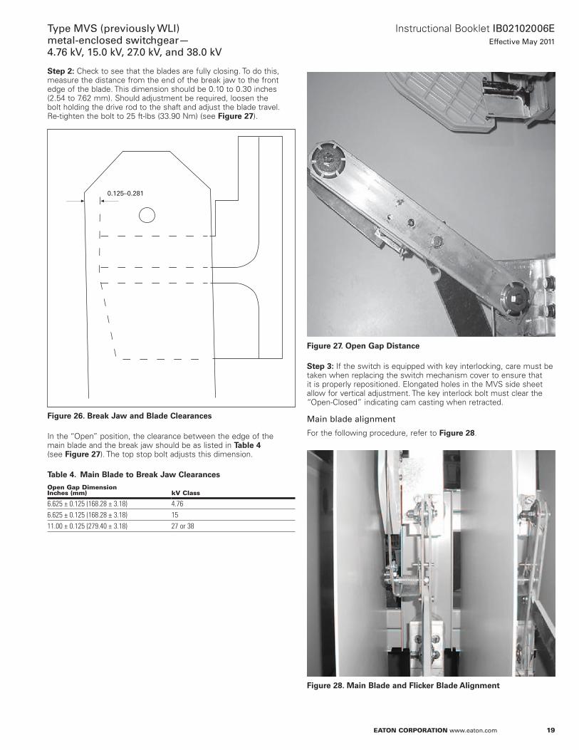
Step 2e: Check to see that the blades are fully closing . To do this, measure the distance from the end of the break jaw to the front edge of the blade . This dimension should be 0 .10 to 0 .30 inches (2 .54 to 7 .62 mm) . Should adjustment be required, loosen the bolt holding the drive rod to the shaft and adjust the blade travel . Re-tighten the bolt to 25 ft-lbs (33 .90 Nm) (see Figure 27) .
Figure 26. Break Jaw and Blade Clearances
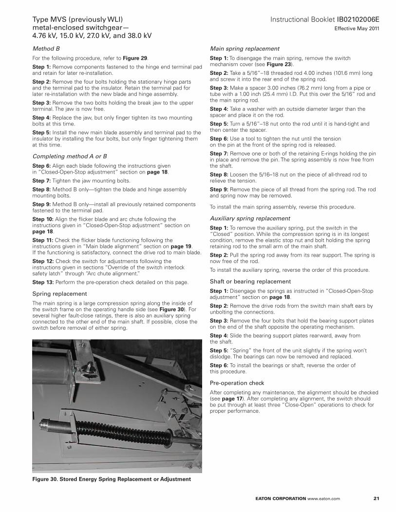
In the “Open” position, the clearance between the edge of the main blade and the break jaw should be as listed in Table 4 (see Figure 27) . The top stop bolt adjusts this dimension .
Table 4. Main Blade to Break Jaw Clearances
open Gap Dimensioninches (mm) kV class
6.625 ± 0.125 (168.28 ± 3.18) 4.766.625 ± 0.125 (168.28 ± 3.18) 1511.00 ± 0.125 (279.40 ± 3.18) 27 or 38
0.125–0.281
Figure 27. Open Gap Distance
Step 3e: If the switch is equipped with key interlocking, care must be taken when replacing the switch mechanism cover to ensure that it is properly repositioned . Elongated holes in the MVS side sheet allow for vertical adjustment . The key interlock bolt must clear the “Open-Closed” indicating cam casting when retracted .
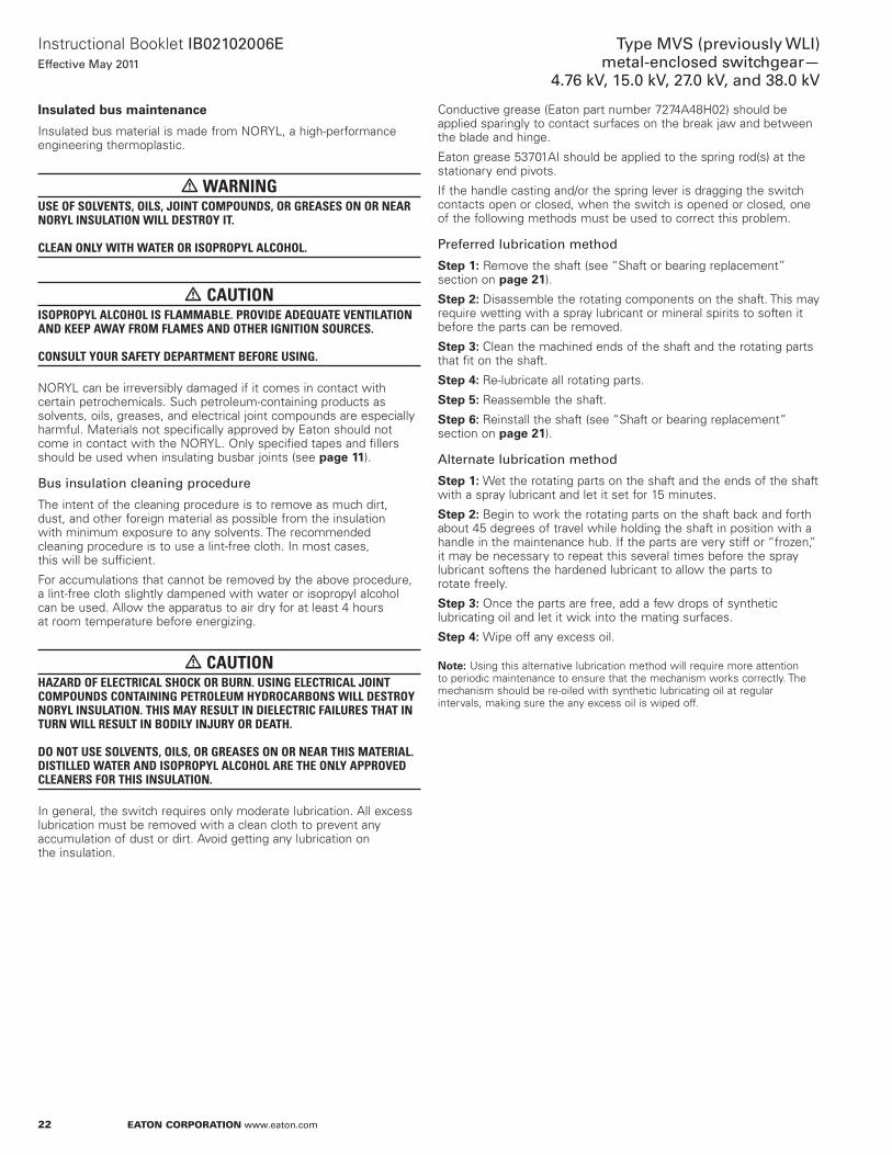
Main blade alignment
For the following procedure, refer to Figure 28 .
Figure 28. Main Blade and Flicker Blade Alignment

20
Instructional Booklet IB02102006EEffective May 2011
Type MVS (previously WLI)metal-enclosed switchgear—
4.76 kV, 15.0 kV, 27.0 kV, and 38.0 kV
eaton corporation www.eaton.com
Step 1e: Loosen the four hinge bolts and the two break jaw bolts . Insert the removable handle in the maintenance hub on the shaft and “Close” the switch .
otee:N For safety purposes, the switch will not fully “Close” and will revert to the “Open” position if pressure on the handle is released .
Step 2e: Hold the switch in the “Closed” position with the handle and tighten the bolts on both the hinge and jaw per the torque specifications given on page 28 .
Arc chute alignment
For the following procedure, refer to Figure 28 .
Step 1e: Loosen the two arc chute mounting bolts . Adjust the arc chute so that its opening is parallel to the main blade then lightly tighten the mounting bolts .
Step 2e: Using the blade alignment hub, slowly close the switch and check that the flicker blade is in line with the arc chute opening . If necessary, move the arc chute left or right until it lines up with the flicker blade .
Step 3e: Tighten the arc chute mounting bolts and recheck the alignment .
Vertical position of break jaw
Step 1e: Close the switch . Check that the upper spacers of the main blades are 0 .1875 ± 0 .0625 inches (4 .76 ± 1 .59 mm) above the tops of the break jaws (see Figure 22) .
Step 2e: If they are not, loosen the bolts holding the break jaw and adjust as necessary . When the setting is correct, tighten bolts to proper torque value (see page 28) .
Break jaw bolt and hinge contact bolt tightness
The disk springs on the main blade assembly must provide the necessary contact pressure between the main blades and stationary mating parts when the switch is “Closed .” At the break jaw end, the elastic stop nut must be removed, then a sensitive torque wrench used to set the proper contact pressure as given in Table 5 .
Table 5. Necessary Contact Pressure
Fault-close rating,ka asymmetrical
torque in-lb (nm)
40 20 (2.260)61 25 (2.825)
For the hinge end, there are two configurations:
1. If there is only an elastic stop nut installed, tighten it to 25 ft-lb (33 .90 Nm), and then back off the nut one full turn .
2. If there is an elastic stop nut that jambs a standard hex nut, remove the elastic stop nut, tighten the standard hex nut to 20 ft-lb (27 .12 Nm), then back off one full turn . Reinstall the locking nut and jamb it against the standard hex nut, being careful not to turn either the bolt or the standard nut .
otee:N Standard ohm readings between the top terminal pad and the bottom terminal pad on each pole are not to exceed 60 micro ohms .
Replacement procedures
Main blade subassembly and break jaw replacement
The switch should be in the “Closed” position . Disconnect the drive rod link from the main blade assembly by removing the clevis pins (see Figure 27) .
Method A
For the following procedure, refer to Figure 29 .
Figure 29. Main and Flicker Blade Replacement. Notice the Hinge Bolt Is Pulled Out to Indicate the Method of Replacement
Step 1e: Remove the bolt and elastic stop nut holding the switch blades to the stationary hinge parts . The main blade and flicker blade assembly are now freed and may be removed . The terminal pad will remain in place .
Step 2e: Remove the two bolts holding the break jaw to the upper terminal . The jaw is now free .
Step 3e: Replace the jaw, but only finger tighten its two mounting bolts at this time .
Step 4e: Remove the contact pressure bolt on the hinge end of the blade assembly, then separate the blade assembly from the stationary hinge parts .
Step 5e: Replace the main blade assembly on the stationary hinge parts and tighten the elastic stop nut to 20 ft-lbs (27 .12 Nm) on the hinge end of the blade, then back off one full turn .
21
Instructional Booklet IB02102006EEffective May 2011
Type MVS (previously WLI)metal-enclosed switchgear—4.76 kV, 15.0 kV, 27.0 kV, and 38.0 kV
eaton corporation www.eaton.com
Method B
For the following procedure, refer to Figure 29 .
Step 1e: Remove components fastened to the hinge end terminal pad and retain for later re-installation .
Step 2e: Remove the four bolts holding the stationary hinge parts and the terminal pad to the insulator . Retain the terminal pad for later re-installation with the new blade and hinge assembly .
Step 3e: Remove the two bolts holding the break jaw to the upper terminal . The jaw is now free .
Step 4e: Replace the jaw, but only finger tighten its two mounting bolts at this time .
Step 5e: Install the new main blade assembly and terminal pad to the insulator by installing the four bolts, but only finger tightening them at this time .
Completing method A or B
Step 6e: Align each blade following the instructions given in “Closed-Open-Stop adjustment” section on page 18 .
Step 7e: Tighten the jaw mounting bolts .
Step 8e: Method B only—tighten the blade and hinge assembly mounting bolts .
Step 9e: Method B only—install all previously retained components fastened to the terminal pad .
Step 10e: Align the flicker blade and arc chute following the instructions given in “Closed-Open-Stop adjustment” section on page 18 .
Step 11e: Check the flicker blade functioning following the instructions given in “Main blade alignment” section on page 19 . If the functioning is satisfactory, connect the drive rod to main blade .
Step 12e: Check the switch for adjustments following the instructions given in sections “Override of the switch interlock safety latch” through “Arc chute alignment .”
Step 13e: Perform the pre-operation check detailed on this page .
Spring replacement
The main spring is a large compression spring along the inside of the switch frame on the operating handle side (see Figure 30) . For several higher fault-close ratings, there is also an auxiliary spring connected to the other end of the main shaft . If possible, close the switch before removal of either spring .
Figure 30. Stored Energy Spring Replacement or Adjustment
Main spring replacement
Step 1e: To disengage the main spring, remove the switch mechanism cover (see Figure 23) .
Step 2e: Take a 5/16”–18 threaded rod 4 .00 inches (101 .6 mm) long and screw it into the rear end of the spring rod .
Step 3e: Make a spacer 3 .00 inches (76 .2 mm) long from a pipe or tube with a 1 .00 inch (25 .4 mm) I .D . Put this over the 5/16” rod and the main spring rod .
Step 4e: Take a washer with an outside diameter larger than the spacer and place it on the rod .
Step 5e: Turn a 5/16”–18 nut onto the rod until it is hand-tight and then center the spacer .
Step 6e: Use a tool to tighten the nut until the tension on the pin at the front of the spring rod is released .
Step 7e: Remove one or both of the retaining E-rings holding the pin in place and remove the pin . The spring assembly is now free from the shaft .
Step 8e: Loosen the 5/16–18 nut on the piece of all-thread rod to relieve the tension .
Step 9e: Remove the piece of all thread from the spring rod . The rod and spring now may be removed .
To install the main spring assembly, reverse this procedure .
Auxiliary spring replacement
Step 1e: To remove the auxiliary spring, put the switch in the “Closed” position . While the compression spring is in its longest condition, remove the elastic stop nut and bolt holding the spring retaining rod to the small arm of the main shaft .
Step 2e: Pull the spring rod away from its rear support . The spring is now free of the rod .
To install the auxiliary spring, reverse the order of this procedure .
Shaft or bearing replacement
Step 1e: Disengage the springs as instructed in “Closed-Open-Stop adjustment” section on page 18 .
Step 2e: Remove the drive rods from the switch main shaft ears by unbolting the connections .
Step 3e: Remove the four bolts that hold the bearing support plates on the end of the shaft opposite the operating mechanism .
Step 4e: Slide the bearing support plates rearward, away from the shaft .
Step 5e: “Spring” the front of the unit slightly if the spring won’t dislodge . The bearings can now be removed and replaced .
Step 6e: To install the bearings or shaft, reverse the order of this procedure .
Pre-operation check
After completing any maintenance, the alignment should be checked (see page 17) . After completing any alignment, the switch should be put through at least three “Close-Open” operations to check for proper performance .
22
Instructional Booklet IB02102006EEffective May 2011
Type MVS (previously WLI)metal-enclosed switchgear—
4.76 kV, 15.0 kV, 27.0 kV, and 38.0 kV
eaton corporation www.eaton.com
Insulated bus maintenance
Insulated bus material is made from NORYL, a high-performance engineering thermoplastic .
WARNINGUSE OF SOLVENTS, OILS, JOINT COMPOUNDS, OR GREASES ON OR NEAR NORyL INSULATION WILL DESTROy IT. CLEAN ONLy WITH WATER OR ISOPROPyL ALCOHOL.
CAUTIONISOPROPyL ALCOHOL IS FLAMMABLE. PROVIDE ADEQUATE VENTILATION AND KEEP AWAy FROM FLAMES AND OTHER IGNITION SOURCES. CONSULT yOUR SAFETy DEPARTMENT BEFORE USING.
NORYL can be irreversibly damaged if it comes in contact with certain petrochemicals . Such petroleum-containing products as solvents, oils, greases, and electrical joint compounds are especially harmful . Materials not specifically approved by Eaton should not come in contact with the NORYL . Only specified tapes and fillers should be used when insulating busbar joints (see page 11) .
Bus insulation cleaning procedure
The intent of the cleaning procedure is to remove as much dirt, dust, and other foreign material as possible from the insulation with minimum exposure to any solvents . The recommended cleaning procedure is to use a lint-free cloth . In most cases, this will be sufficient .
For accumulations that cannot be removed by the above procedure, a lint-free cloth slightly dampened with water or isopropyl alcohol can be used . Allow the apparatus to air dry for at least 4 hours at room temperature before energizing .
CAUTIONHAzARD OF ELECTRICAL SHOCK OR BURN. USING ELECTRICAL JOINT COMPOUNDS CONTAINING PETROLEUM HyDROCARBONS WILL DESTROy NORyL INSULATION. THIS MAy RESULT IN DIELECTRIC FAILURES THAT IN TURN WILL RESULT IN BODILy INJURy OR DEATH. DO NOT USE SOLVENTS, OILS, OR GREASES ON OR NEAR THIS MATERIAL. DISTILLED WATER AND ISOPROPyL ALCOHOL ARE THE ONLy APPROVED CLEANERS FOR THIS INSULATION.
In general, the switch requires only moderate lubrication . All excess lubrication must be removed with a clean cloth to prevent any accumulation of dust or dirt . Avoid getting any lubrication on the insulation .
Conductive grease (Eaton part number 7274A48H02) should be applied sparingly to contact surfaces on the break jaw and between the blade and hinge .
Eaton grease 53701AI should be applied to the spring rod(s) at the stationary end pivots .
If the handle casting and/or the spring lever is dragging the switch contacts open or closed, when the switch is opened or closed, one of the following methods must be used to correct this problem .
Preferred lubrication method
Step 1e: Remove the shaft (see “Shaft or bearing replacement” section on page 21) .
Step 2e: Disassemble the rotating components on the shaft . This may require wetting with a spray lubricant or mineral spirits to soften it before the parts can be removed .
Step 3e: Clean the machined ends of the shaft and the rotating parts that fit on the shaft .
Step 4e: Re-lubricate all rotating parts .
Step 5e: Reassemble the shaft .
Step 6e: Reinstall the shaft (see “Shaft or bearing replacement” section on page 21) .
Alternate lubrication method
Step 1e: Wet the rotating parts on the shaft and the ends of the shaft with a spray lubricant and let it set for 15 minutes .
Step 2e: Begin to work the rotating parts on the shaft back and forth about 45 degrees of travel while holding the shaft in position with a handle in the maintenance hub . If the parts are very stiff or “frozen,” it may be necessary to repeat this several times before the spray lubricant softens the hardened lubricant to allow the parts to rotate freely .
Step 3e: Once the parts are free, add a few drops of synthetic lubricating oil and let it wick into the mating surfaces .
Step 4e: Wipe off any excess oil .
otee:N Using this alternative lubrication method will require more attention to periodic maintenance to ensure that the mechanism works correctly . The mechanism should be re-oiled with synthetic lubricating oil at regular intervals, making sure the any excess oil is wiped off .

23
Instructional Booklet IB02102006EEffective May 2011
Type MVS (previously WLI)metal-enclosed switchgear—4.76 kV, 15.0 kV, 27.0 kV, and 38.0 kV
eaton corporation www.eaton.com
Duplex switchgear configurationWhen supplied, the duplex configuration consists of two MVS switches feeding a common bus, which in turn is connected to the set of fuses in one of the switch sections . This arrangement allows the selection of either of two incoming lines to feed a load (see Figure 31) .
Figure 31. Duplex Selective Switch Configuration
This arrangement is supplied with key interlocking for safe opera-tion . Key interlocking normally consists of a lock on each switch to lock the switch in the “Open” position and a lock on each door to lock each door closed . Each lock is keyed alike . Only one key is to be available to operating personnel . Because the key is retained in its lock when a switch is “Closed” or when a door is opened, two things are ensured:
1. Only one switch may be closed at a time . This prevents paralleling of incoming lines and prevents opening either enclosure door .
2. Both switches are locked in the open position to unlock either main door . This prevents access to the common bus or fuses or being able to “Close” either switch .
CAUTIONHAzARD OF ELECTRICAL SHOCK OR BURN. FAILURE TO IMPLEMENT AND USE THE KEy INTERLOCKING SySTEM PROVIDED WILL EXPOSE PERSONNEL TO DANGEROUS VOLTAGES. IMPLEMENT AND USE THE KEy INTERLOCKING SySTEM PROVIDED. USE ONLy THE NUMBER OF KEyS REQUIRED FOR CORRECT OPERATION. ALL EXTRA KEyS MUST BE EITHER DESTROyED OR MADE INACCESSIBLE TO OPERATING PERSONNEL.
Line
LO LO
LD LD
Load
Line
Motor operationMotor-operated MVS switch
The motor-operated MVS switch is essentially a standard manually operated switch with a motor driven linear actuator connected to the switch mechanism . Because all basic switch parts are identical to those of the standard, manually operated switch, sections of this instruction book pertaining to installation, inspection before startup, maintenance, and parts replacement also apply to the motor operated switch .
Table 6. MVS Switch Motor Operator Current Requirements
nominal Voltage e/r amperes
120 Vac 3.024 Vdc 7.048 Vdc 3.5125 Vdc 1.5
Time to open or close an MVS switch with an integral motor operator is about 5 seconds for the AC versions and about 10 seconds for the DC versions .
Receiving and startup
For MVS switches, units are shipped with the linear actuator installed .
Electrical operation
The preferred voltage for the linear actuator to operate is 120 Vac, and control power is normally supplied by the customer . See the job drawings for an electrical schematic diagram and wiring diagram of the motor operator circuitry to determine the actual operating voltage and power source .
Safety interlocking
For an MVS motor-operated switch, safety interlocking is based upon a key interlock system . The switch mechanism key interlock must have an integral electrical switch . Extending the interlock bolt would mechanically lock the MVS switch in the “Open” position, would open the electrical control power circuit for the motor operator, and would release the key . With the key, a person can then unlock the key interlock on the switch enclosure door .
This scheme prevents closing the switch with the door open as well as prevents opening of the enclosure door with the switch closed .

24
Instructional Booklet IB02102006EEffective May 2011
Type MVS (previously WLI)metal-enclosed switchgear—
4.76 kV, 15.0 kV, 27.0 kV, and 38.0 kV
eaton corporation www.eaton.com
WARNINGOPERATING AN MVS SWITCH WITH A KEy INTERLOCK BOLT EXTENDED WILL RESULT IN EQUIPMENT DAMAGE AND MAy ALSO EXPOSE A PERSON TO BODILy INJURy OR DEATH. THE KEy MUST BE INSERTED INTO THE INTERLOCK AND ROTATED TO RETRACT THE LOCKING BOLT BEFORE OPERATING AN MVS SWITCH.
Hand operation of a motor operated switch
A special pin connects the linear actuator to the switch operator . Loosen the screw holding the pin in place and remove this pin (see Figure 32) . Remove the bottom support pin holding the linear actuator, pull it out sufficiently to permit unplugging the linear actuator and removing it (see Figure 33) . The switch may now be manually operated with the removable handle .
Figure 32. Special Pin and Screw at the Top of the Motor Actuator Piston
Figure 33. Bottom Support Pin
WARNINGDEFEATING OR DISENGAGING SAFETy INTERLOCKS ON AN MVS SWITCH THAT IS CONNECTED TO A POWER SOURCE MAy RESULT IN PROPERTy DAMAGE, BODILy INJURy, OR DEATH. DO NOT DEFEAT OR DISENGAGE ANy SAFETy INTERLOCKS.
Maintenance
The linear actuator itself is completely weather-sealed . The linear actuator and its associated bearings are lubricated for their normal life many times in excess of the main switch and therefore require no maintenance .

25
Instructional Booklet IB02102006EEffective May 2011
Type MVS (previously WLI)metal-enclosed switchgear—4.76 kV, 15.0 kV, 27.0 kV, and 38.0 kV
eaton corporation www.eaton.com
electromechanical stored energy release (shunt trip)Description
The stored energy release feature of the MVS load interrupter switch allows the operator to manually compress the main operating spring storing the spring energy to “Open” or “Close” the switch upon lifting the trigger latch . When the latch is released, the stored energy in the main operating spring is released to rotate the main shaft to “Close” or to “Open” the switch (see Figure 35) . This feature is only available on 4 .76 kV or 15 kV class MVS switches .
Table 7. MVS Switch Electromechanical Stored Energy Release Coil Data. Tolerancee: ± 15% Vac or Vdc
nominal Voltage e/r amperes
120 Vac 11.2240 Vac 7.450 Vdc 7.4125 Vdc 5.0250 Vdc 2.5240 Vac capacitor trip 2.5
Figure 34. Stored Energy Mechanism
WARNINGDEVIATING FROM THE WARNING LABEL ON SWITCHGEAR WILL RESULT IN EQUIPMENT DAMAGE AND MAy ALSO EXPOSE A PERSON TO BODILy INJURy OR DEATH. FOLLOW EXACTLy THE OPERATING INSTRUCTIONS ON THE LABEL.
CAUTIONCHANGING THE SWITCH POSITION WITH THE SWITCH OPERATING HANDLE WILL RESULT IN DAMAGE TO THE SWITCH. IF THE SWITCH STATUS NAMEPLATE INDICATES THAT THE SPRING IS CHARGED, THE TRIGGER LATCH MUST BE RELEASED TO CHANGE THE POSITION OF THE SWITCH.
Charging the spring to “Close” or “Open” the switch
To initiate the opening or closing action, the handle is inserted into the handle casting and is rotated upward for the closing action and downward for the opening action through an angle of 120 degrees . The switch main operating spring is now charged and the trigger latch is ready to be released to “Open” or “Close” the switch .
Closing the switch
Starting conditione: The switch is “Open” and the spring has been charged by the action described above (see Figure 35) .
When the trigger latch is lifted upward, either manually or by the action of the trigger coil, the blocking mechanism is released, permitting the switch to “Close .” The final result is a “Closed” switch with the operating spring in an uncharged condition (see Figure 36) .
Opening the switch
Starting conditione: The switch is “Closed” and the spring has been charged by the action in described above (see Figure 37) .
When the trigger latch is lifted upward, either manually or by the action of the trigger coil, the blocking mechanism is released permitting the switch to “Open .” The final result is an “Open” switch with the operating spring in an uncharged condition (see Figure 35) .

26
Instructional Booklet IB02102006EEffective May 2011
Type MVS (previously WLI)metal-enclosed switchgear—
4.76 kV, 15.0 kV, 27.0 kV, and 38.0 kV
eaton corporation www.eaton.com
Figure 35. Switch Open, Spring Not Charged
Figure 36. Switch Open, Spring Charged
Electrical Trigger Coil
Hand Trip Lever
Trigger Latch
Teeter Assembly
Trip Link
Spring Rod
Spring
Main Shaft
Spring Rod Pin
Spring Lever
Main Lever Stop Angle Assembly
Main Lever (Pinned to Main Shaft)
Electrical Trigger Coil
Hand Trip Lever
Trigger Latch
Teeter Assembly
Trip Link
Spring Rod
SpringMain Lever
(Pinned to Main Shaft)
Main Lever Stop Angle Assembly
Main Shaft
Spring Rod PinSpring Lever
Figure 37. Switch Closed, Spring Not Charged
Figure 38. Switch Closed, Spring Charged
Electrical Trigger Coil
Hand Trip Lever
Trigger Latch
Teeter Assembly
Trip Link
Spring Rod
Spring
Main Lever (Pinned to Main Shaft)
Main Lever Stop Angle Assembly
Main Shaft
Spring Rod Pin
Spring Lever
Electrical Trigger Coil
Hand Trip Lever
Trigger Latch
Teeter Assembly
Trip Link
Spring Rod
Spring
Main Shaft
Spring Rod Pin
Spring Lever
Main Lever Stop Angle Assembly
Main Lever (Pinned to Main Shaft)
27
Instructional Booklet IB02102006EEffective May 2011
Type MVS (previously WLI)metal-enclosed switchgear—4.76 kV, 15.0 kV, 27.0 kV, and 38.0 kV
eaton corporation www.eaton.com
Main shaft position with door interlock (shaft blocking cam)
WARNINGDEFEATING THE SHAFT BLOCKING CAM-DOOR INTERLOCK WHEN THE SWITCH IS ENERGIzED MAy RESULT IN SEVERE INJURy OR DEATH. DE-ENERGIzE THE SWITCH AND GROUND ALL LIVE PARTS BEFORE DEFEATING THIS INTERLOCK TO PERFORM MAINTENANCE, ADJUSTMENT, AND INSPECTION PROCEDURES.
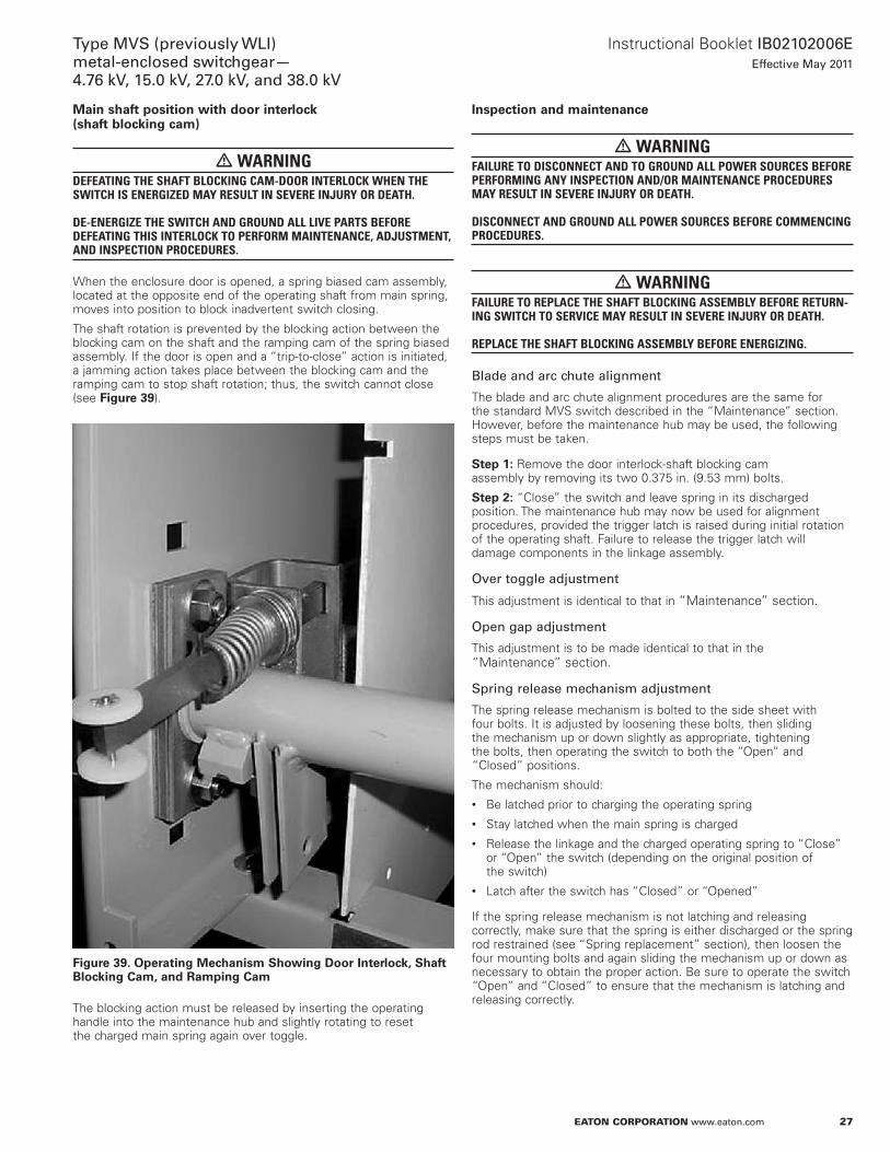
When the enclosure door is opened, a spring biased cam assembly, located at the opposite end of the operating shaft from main spring, moves into position to block inadvertent switch closing .
The shaft rotation is prevented by the blocking action between the blocking cam on the shaft and the ramping cam of the spring biased assembly . If the door is open and a “trip-to-close” action is initiated, a jamming action takes place between the blocking cam and the ramping cam to stop shaft rotation; thus, the switch cannot close (see Figure 39) .
Figure 39. Operating Mechanism Showing Door Interlock, Shaft Blocking Cam, and Ramping Cam
The blocking action must be released by inserting the operating handle into the maintenance hub and slightly rotating to reset the charged main spring again over toggle .
Inspection and maintenance
WARNINGFAILURE TO DISCONNECT AND TO GROUND ALL POWER SOURCES BEFORE PERFORMING ANy INSPECTION AND/OR MAINTENANCE PROCEDURES MAy RESULT IN SEVERE INJURy OR DEATH. DISCONNECT AND GROUND ALL POWER SOURCES BEFORE COMMENCING PROCEDURES.
WARNINGFAILURE TO REPLACE THE SHAFT BLOCKING ASSEMBLy BEFORE RETURN-ING SWITCH TO SERVICE MAy RESULT IN SEVERE INJURy OR DEATH. REPLACE THE SHAFT BLOCKING ASSEMBLy BEFORE ENERGIzING.
Blade and arc chute alignment
The blade and arc chute alignment procedures are the same for the standard MVS switch described in the “Maintenance” section . However, before the maintenance hub may be used, the following steps must be taken .
Step 1e: Remove the door interlock-shaft blocking cam assembly by removing its two 0 .375 in . (9 .53 mm) bolts .
Step 2e: “Close” the switch and leave spring in its discharged position . The maintenance hub may now be used for alignment procedures, provided the trigger latch is raised during initial rotation of the operating shaft . Failure to release the trigger latch will damage components in the linkage assembly .
Over toggle adjustment
This adjustment is identical to that in “Maintenance” section .
Open gap adjustment
This adjustment is to be made identical to that in the “Maintenance” section .
Spring release mechanism adjustment
The spring release mechanism is bolted to the side sheet with four bolts . It is adjusted by loosening these bolts, then sliding the mechanism up or down slightly as appropriate, tightening the bolts, then operating the switch to both the “Open” and “Closed” positions .
The mechanism should:• Be latched prior to charging the operating spring• Stay latched when the main spring is charged• Release the linkage and the charged operating spring to “Close”
or “Open” the switch (depending on the original position of the switch)
• Latch after the switch has “Closed” or “Opened”
If the spring release mechanism is not latching and releasing correctly, make sure that the spring is either discharged or the spring rod restrained (see “Spring replacement” section), then loosen the four mounting bolts and again sliding the mechanism up or down as necessary to obtain the proper action . Be sure to operate the switch “Open” and “Closed” to ensure that the mechanism is latching and releasing correctly .

Eaton CorporationElectrical Sector1111 Superior Ave .Cleveland, OH 44114United States877-ETN-CARE (877-386-2273)Eaton .com
© 2011 Eaton CorporationAll Rights ReservedPrinted in USAPublication No . IB02102006E / Z11145May 2011
Eaton is a registered trademark of Eaton Corporation .
All other trademarks are property of their respective owners .
Instructional Booklet IB02102006EEffective May 2011
Type MVS (previously WLI)metal-enclosed switchgear—
4.76 kV, 15.0 kV, 27.0 kV, and 38.0 kV
MVS switchgear bolt tightness for bus connections and connections to switch terminal padsUse the following torque values for tightening hardware where conductors are connected to each other or to switch terminal pads .
Table 8. Hardware Torque Values
Bolt DiameterDecimal Sizeinches (mm)
Bolt Diameter Standard
nominal torqueft-lb (nm)
0.250 (6.35) 1/4–20 4 (5.42)0.312 (7.93) 5/16–18 8 (10.85)0.375 (9.53) 3/8–16 25 (33.90)0.500 (12.70) 1/2–13 50 (67.80)0.625 915.88) 5/8–11 65 (88.13)
common renewal parts
Table 9. Common Renewal Parts
part DescriptionQuantity per Switch
Style number
Three-pole blade and break jaw assembly kit, 600A, 4.76/15 kV
1 7278A27G01
Three-pole blade and break jaw assembly kit, 1200A, 4.76/15 kV
1 7278A27G02
Three-pole blade and break jaw assembly kit, 27/38 kV
1 7278A27G05
Barrier assembly kit, interphase, 4.76/15 kV 1 7278A27G24Barrier assembly kit, interphase, 27/38 kV 1 7278A27G25Insulator, glass polyester, 4.76 kV 6 4892A97H01Insulator, glass polyester, 15 kV 6 4892A97H02Insulator, epoxy, 4.76 kV 6 4892A97H07Insulator, epoxy, 15 kV 6 4892A97H08Insulator, epoxy, 27/38 kV 6 4892A97H18Drive rod link kit, glass polyester, 4.76 kV 1 7278A27G09Drive rod link kit, glass polyester, 15 kV 1 7278A27G10Drive rod link kit, glass polyester, 27/38 kV 1 7278A27G12Contact grease, 2 oz jar As required 7274A48H02Mechanism grease, 1 lb container As required 53701AI02EAuxiliary switch assembly kit 1 221C395G014.76/15 kV MVS bus support polyester/nylon, 8.00-inch centers
As required 260C003H01
4.76/15 kV MVS bus support polyester/epoxy, 8.00-inch centers
As required 260C265H01
4.76/15 kV MVS bus brace, three-conductor polyester/nylon, 8.00-inch centers
As required 260C005H01
4.76/15 kV MVS bus brace, three-conductor polyester/epoxy, 8.00-inch centers
As required 260C266H01
4.76/15 kV MVS bus brace, two-conductor polyester/nylon, 8.00-inch centers
As required 260C005H03
4.76/15 kV MVS bus brace, two-conductor polyester/epoxy, 8.00-inch centers
As required 260C266H03
Fuse live parts kit, RBA200 4.76 kV (MVS) As required 98A1125G22Fuse live parts kit, RBA200 15 kV (MVS) As required 98A1125G23Fuse live parts kit (WLI), RBA200 25.8 kV or 38 kV As required 7278A27G31Fuse live parts kit, RBA400 4.76 kV (MVS) As required 98A1125G24Fuse live parts kit, RBA400 15 kV (MVS) As required 98A1125G25Fuse live parts kit (WLI), RBA400 25.8 kV or 38 kV As required 7278A2732Fuse live parts kit (WLI), NX 27 kV As required 7278A27G41Fuse live parts kit (WLI), EJO-1 38 kV As required 7278A27G42Set of fuse barriers (4.76/15 kV Class MVS) As required 7278A27G43Set of fuse barriers (27 kV Class or 38 kV Class WLI) As required 7278A27G254.76 kV fuse live parts kit, CLE, 3.00-inch diameter, Ferrule single barrel, 4.76 kV MVS
As required 98A1125G03
4.76 kV fuse live parts kit, CLE, 3.00-inch diameter, Ferrule single barrel, 4.76 kV MVS
As required 98A1125G04
15 kV fuse live parts kit, CLE, 3.00-inch diameter, Ferrule double barrel, 15 kV MVS
As required 98A1125G05
15 kV fuse live parts kit, CLE, 3.00-inch diameter, Ferrule double barrel, 15 kV MVS
As required 98A1125G06
Space heater, 125V, 250W As required 3614A50H01Space heater, 250V, 250W As required 3614A50H02