effective of seismic load on behavior of rectangular shear · effective of seismic load on behavior...
TRANSCRIPT

© 2017. Mahdi Hosseini. This is a research/review paper, distributed under the terms of the Creative Commons Attribution-Noncommercial 3.0 Unported License http://creativecommons.org/ licenses/by-nc/3.0/), permitting all non commercial use, distribution, and reproduction in any medium, provided the original work is properly cited.
Global Journal of Researches in Engineering: E Civil And Structural Engineering Volume 17 Issue 3 Version 1.0 Year 2017 Type: Double Blind Peer Reviewed International Research Journal Publisher: Global Journals Inc. (USA) Online ISSN: 2249-4596 & Print ISSN: 0975-5861
Effective of Seismic Load on Behavior of Rectangular Shear Wall in RC Frame structure
By Mahdi Hosseini Jawaharlal Nehru Technological University
Abstract- The usefulness of shear walls in the structural planning of multistory buildings has long been recognized. When walls are situated in advantageous positions in a building, they can be very efficient in resisting lateral loads originating from wind or earthquakes. Incorporation of shear wall has become inevitable in multi-storey building to resist lateral forces. In present work, twenty storey buildings have been modeled using software ETABS by dynamic analysis. All the analyses has been carried out as per the Indian Standard code books. Based on the literature of previous studies most effective positioning of shear walls has been chosen. This study is done on RC framed multistory building with RC shear walls with fixed support conditions. This paper aims to study the behaviour of reinforced concrete building by conducting dynamic analysis for most suited positions and location of Rectangular shear wall. Estimation of structural response such as; axial force, shear force, torsion, moment, storey drift is carried out. Dynamic responses under zone V earthquake as per IS 1893 (part 1): 2002 have been carried out.
Keywords: rectangular shear wall, frame structure, dynamic analysis, seismic load, structural response.
GJRE-E Classification: FOR Code: 090506
EffectiveofSeismicLoadonBehaviorofRectangularShearWallinRCFramestructure
Strictly as per the compliance and regulations of:
Effective o on Behavior of Rectangular Shear Wall in RC Frame Structure
Mahdi Hosseini
Keywords:
rectangular shear wall, frame structure, dynamic analysis, seismic load, structural response.
I.
Introduction
Author:
MAHDI HOSSEINI, P.h.D. scholar student in Structural Engineering, Dept. of Civil Engineering, Jawaharlal Nehru Technological University Hyderabad (JNTUH), Hyderabad, Telengana, India. e-mail: [email protected]
earthquake, distance from the earthquake source(epicenter), local ground conditions that may amplify ground
shaking (or dampen it), the weight
(or mass) of the structure, and the type of structural system
and its ability to with stand abusive cyclic loading. In theory and practice, the lateral force that a building experiences from an earthquake increases in direct proportion with the acceleration of ground motion at the building site and the mass of the building (i.e., a doubling in ground motion acceleration or building mass will double the load).This theory rests on the simplicity and validity of Newton’s law of physics: F = m x a, where ‘F’ represents force, ‘m’ represents mass or weight, and ‘a’ represents acceleration.
b)
Why are Buildings with Shear Walls Preferred in Seismic Zones?
Reinforced concrete (RC) buildings often have vertical plate-like RC walls called Shear Walls in addition to slabs, beams and columns. These walls generally start at foundation level and are continuous throughout the building height. Their thickness can be as low as 150mm, or as high as 400mm in high rise buildings. Shear walls are usually provided along both length and width of buildings. Shear walls are like vertically-oriented wide beams that carry earthquake loads downwards to the foundation.
“We cannot afford to build concrete buildings meant to resist severe earthquakes without shear walls.” Mark Fintel, a noted consulting engineer in USA Shear walls in high seismic regions requires special detailing. However, in past earthquakes, even buildings with sufficient amount of walls that were not specially detailed for seismic performance (but had enough well-distributed reinforcement) were saved from collapse. Shear walls are easy to construct, because reinforcement detailing of walls is relatively straight-forward and therefore easily implemented at site. Shear walls are efficient; both in terms of construction cost properly designed and detailed buildings with Shear walls have shown very good performance in past earthquakes. The overwhelming success of buildings with shear walls in resisting strong earthquakes is summarized in the quote: And effectiveness in minimizing earthquake damage in structural and non- Structural elements (like glass windows and building contents).
© 2017 Global Journals Inc. (US)
Globa
l Jo
urna
l of
Resea
rche
s in E
nginee
ring
(
)Volum
e XVII Issue
III V
ersion
I
19
Year
2017
E
a) Seismic Loadhe seismic weight of building is the sum of seismic weight of all the floors. The seismic weight of each floor is its full dead load plus appropriate amount
of imposed load, the latter being that part of the imposed loads that may reasonably be expected to be attached to the structure at the time of earthquake shaking. It includes the weight of permanent and movable partitions, permanent equipment, a part of the live load, etc. While computing the seismic weight of columns and walls in any storey shall be equally distributed to the floors above and below the storey. Earthquake forces experienced by a building result from ground motions (accelerations) which are also fluctuating or dynamic in nature, in fact they reverse direction some what chaotically. The magnitude of an earthquake force depends on the magnitude of an
T
f Seismic Load
Abstract- The usefulness of shear walls in the structural planning of multistory buildings has long been recognized. When walls are situated in advantageous positions in a building, they can be very efficient in resisting lateral loads originating from wind or earthquakes. Incorporation of shear wall has become inevitable in multi-storey building to resist lateral forces. In present work, twenty storey buildings have been modeled using software ETABS by dynamic analysis. All the analyses has been carried out as per the Indian Standard code books. Based on the literature of previous studies most effective positioning of shear walls has been chosen. This study is done on RC framed multistory building with RC shear walls with fixed support conditions. This paper aims to study the behaviour of reinforced concrete building by conducting dynamic analysis for most suited positions and location of Rectangular shear wall. Estimation of structural response such as; axial force, shear force, torsion, moment, storey drift is carried out. Dynamic responses under zone V earthquake as per IS 1893 (part 1): 2002 have been carried out.
When a building is subjected to wind or earthquake load, various types of failure must be prevented:
• Slipping off the foundation (sliding)• Overturning and uplift (anchorage failure)

Effective of Seismicload on Behavior of Rectangular Shear Wall in RC Frame structure
© 2017 Global Journals Inc. (US)
Globa
l Jo
urna
l of
Resea
rche
s in E
nginee
ring
(
)Volum
e XVII Issue
III V
ersion
I
20
Year
2017
E
• Shear distortion (drift or racking deflection)• Collapse (excessive racking deflection)
Most RC buildings with shear walls also have columns; these columns primarily carry gravity loads (i.e., those due to self-weight and contents of building). Shear walls provide large strength and stiffness to buildings in the direction of their orientation, which significantly reduces lateral sway of the building and thereby reduces damage to structure and its contents.
Since shear walls carry large horizontal earthquake forces, the overturning effects on them are large. Thus, design of their foundations requires special Attention. Shear walls should be provided along preferably both length and width. However, if they are provided along only one direction, a proper grid of beams and columns in the vertical plane (called a moment-resistant frame) must be provided along the other direction to resist strong earthquake effects.
II. Methodology Quite a few methods are available for the
earthquake analysis of buildings; two of them are presented here: 1. Equivalent Static Lateral Force Method (pseudo
static method). 2. Dynamic Analysis.
i. Response spectrum method. ii. Time history method.
a) Dynamic Analysis Dynamic analysis shall be performed to obtain
the design seismic force, and its distribution in different levels along the height of the building, and in the various lateral load resisting element, for the following buildings:
Irregular buildings: All framed buildings higher than 12m in zones IV and V, and those greater than 40m in height in zones II and III.
The analysis of model for dynamic analysis of buildings with unusual configuration should be such that it adequately models the typ es of irregularities present in the building configuration. Buildings with plan irregularities, as defined in Table 4 of IS code: 1893-
2002 cannot be modeled for dynamic analysis. Dynamic analysis may be performed either by
the Time History Method or by the Response Spectrum Method.. b)
Time History Method
The usage of this method shall be on an appropriate ground motion and shall be performed using accepted principles of dynamics. In this method, the mathematical model of the building is subjected to accelerations from earthquake records that represent the expected earthquake at the base of the structure.
c)
Response Spectrum Method The word spectrum in engineering conveys the
idea that the response of buildings having a broad range of periods is summarized in a single graph. This method shall be performed using the design spectrum specified in code or by a site-specific design spectrum for a structure prepared at a project site. The values of damping for building may be taken as 2 and 5 percent of the critical, for the purposes of dynamic of steel and reinforce concrete buildings, respectively. For most buildings, inelastic response can be expected to occur during a major earthquake, implying that an inelastic analysis is more proper for design. However, in spite of the availability of nonlinear inelastic programs, they are not used in typical design practice because:
1.
Their proper use requires knowledge of their inner workings and theories. design criteria and
2. Result produced are difficult to interpret and apply
to traditional design criteria , and 3. The necessary computations are expensive.
Therefore, analysis in practice typically use linear elastic procedures based on the response spectrum method. The response spectrum analysis is the preferred method because it is easier to use.
III. Numerical Analyses
b) Geometrical Properties
1. No. of stories of the Building model=20 2. Column size=500 mm x 500 mm 3. Beam size= 700 mm x 500 mm 4. Slab thickness=200mm
Loads
1. Live Load=3KN/m2 2. Wall Load=12.4KN/m
Effective of Seismicload on Behavior of Rectangular Shear Wall in RC Frame structure
© 2017 Global Journals Inc. (US)
Globa
l Jo
urna
l of
Resea
rche
s in E
nginee
ring
(
)Volum
e XVII Issue
III V
ersion
I
21
Year
2017
E
Wind Coefficients
(i) Wind Speed=50m/s (ii) Terrain Category =2 (iii) Structure Class=B (iv) Risk Coefficient(k1)=1 (v) Topography(k3)=1
c) Material Properties
3. Floor Finishing =1KN/m2 4. Wind load
Seismic Loading
(i) Seismic zone factor(Z)=0.36 (ii) Soil Type= Medium(II) (iii) Response Reduction factor(R) =5% (iv) Story Range=Base to 20 (v) Important factor(I)=1
StructureG+19 earthquake resistant structure with
Rectangular shear wall.
a) Problems in the Building Due to EarthquakeMain problems that would be arising due to
earthquake in the structure are story drift and deflection of the building due to its large height and also torsion and others, so if the structure is proved to be safe in all the above mentioned problems than the structure would be safe in all cases in respect earthquake.
Regular buildings: Those greater than 40m in height in zones IV and V, those greater than 90m in height in zone II and III.
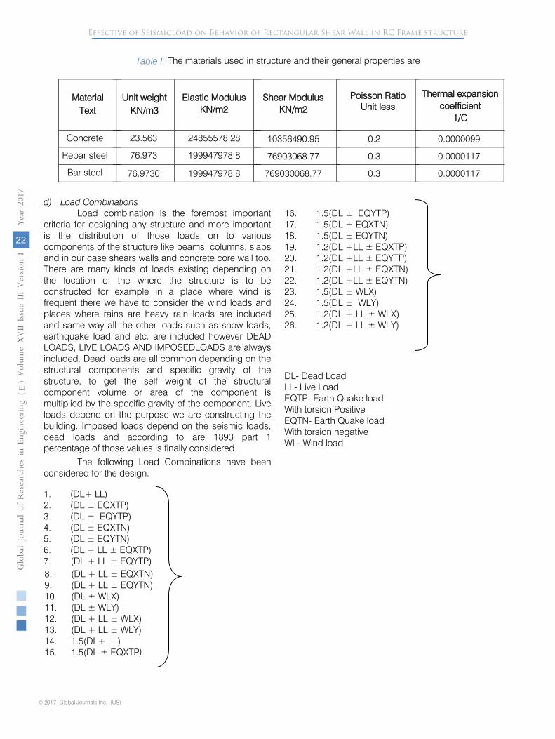
Table I:
The materials used in structure and their general properties are
d)
Load Combinations
Load combination is the foremost important criteria for designing any structure and more important is the distribution of those loads
on to various components of the structure like beams, columns, slabs and in our case shears walls and concrete core wall too. There are many kinds of loads existing depending on the location of the where the structure is to be constructed for example in a
place where wind is frequent there we have to consider the wind loads and places where rains are heavy rain loads are included and same way all the other loads such as snow loads, earthquake load and etc. are included however DEAD LOADS, LIVE LOADS AND IMPOSEDLOADS are always included. Dead loads are all common depending on the structural components and specific gravity of the structure, to get the self weight of the structural component volume or area of the component is multiplied by the specific gravity
of the component. Live loads depend on the purpose we are constructing the building. Imposed loads depend on the seismic loads, dead loads and according to are 1893 part 1 percentage of those values is finally considered.
The following Load Combinations have been considered for the design.
1.
(DL+ LL)
2.
(DL ± EQXTP)
3.
(DL ± EQYTP)
4.
(DL ± EQXTN)
5.
(DL ± EQYTN)
6.
(DL + LL ± EQXTP)
7. (DL + LL ± EQYTP)
8.
(DL + LL ± EQXTN)
9.
(DL + LL ± EQYTN)
10.
(DL ± WLX)
11.
(DL ± WLY)
12.
(DL + LL ± WLX)
13.
(DL + LL ± WLY)
14.
1.5(DL+ LL)
15.
1.5(DL ± EQXTP)
16.
1.5(DL ± EQYTP)
17.
1.5(DL ± EQXTN)
18.
1.5(DL ± EQYTN)
19.
1.2(DL +LL ± EQXTP)
20.
1.2(DL +LL ± EQYTP)
21.
1.2(DL +LL ± EQXTN)
22.
1.2(DL +LL ± EQYTN)
23.
1.5(DL ± WLX)
24.
1.5(DL ± WLY)
25.
1.2(DL + LL ± WLX)
26.
1.2(DL + LL ± WLY)
Effective of Seismicload on Behavior of Rectangular Shear Wall in RC Frame structure
© 2017 Global Journals Inc. (US)
Globa
l Jo
urna
l of
Resea
rche
s in E
nginee
ring
(
)Volum
e XVII Issue
III V
ersion
I
22
Year
2017
E
Concrete 23.563 24855578.28 10356490.95 0.2 0.0000099
Rebar steel 76.973 199947978.8 76903068.77 0.3 0.0000117
Bar steel 76.9730 199947978.8 769030068.77 0.3 0.0000117
DL- Dead LoadLL- Live LoadEQTP- Earth Quake loadWith torsion PositiveEQTN- Earth Quake loadWith torsion negativeWL- Wind load
Material Unit weight Elastic Modulus Shear Modulus Poisson Ratio Thermal expansion coefficientText KN/m3 KN/m2 KN/m2 Unit less
1/C
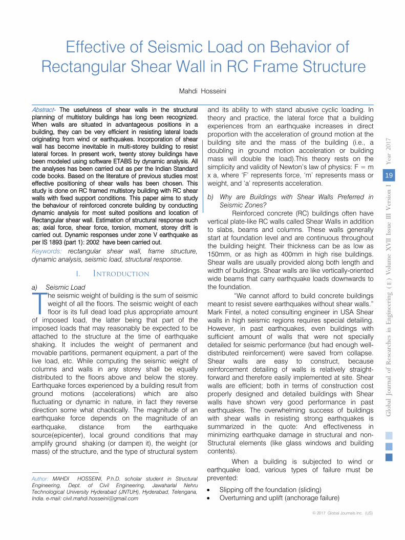
Basic Plan of the Building
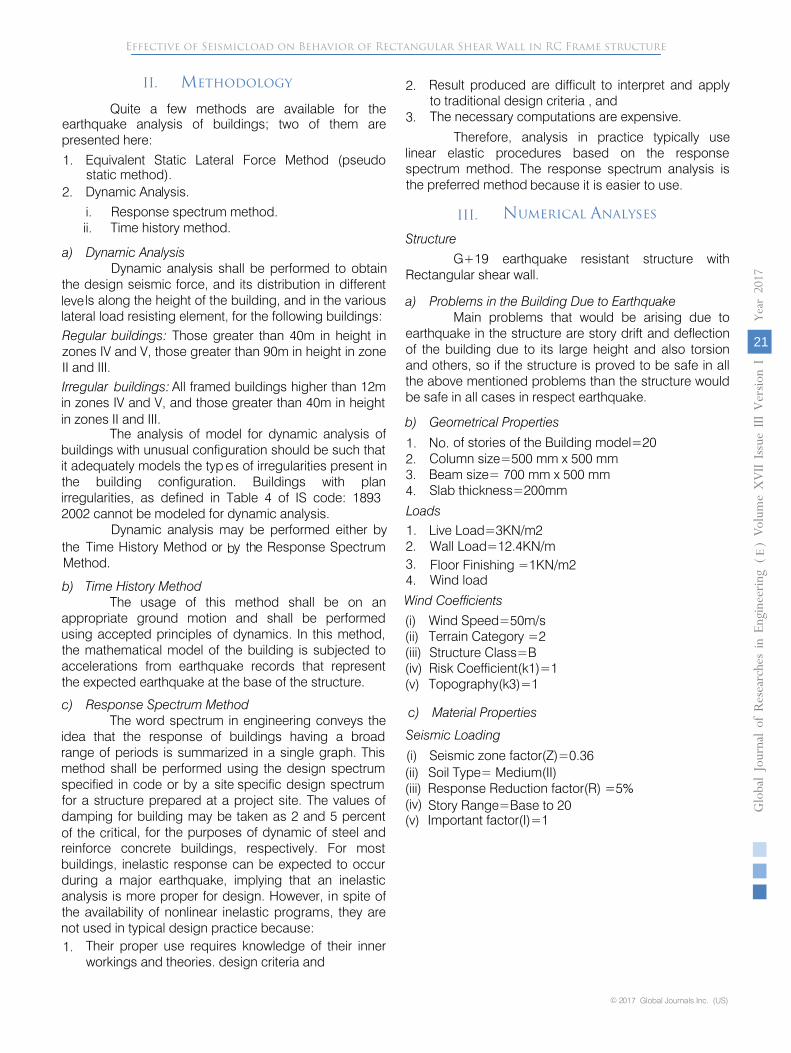
Fig.
2: Elevation of the Building
Fig.
3:
3-D Modeling
Effective of Seismicload on Behavior of Rectangular Shear Wall in RC Frame structure
© 2017 Global Journals Inc. (US)
Globa
l Jo
urna
l of
Resea
rche
s in E
nginee
ring
(
)Volum
e XVII Issue
III V
ersion
I
23
Year
2017
E
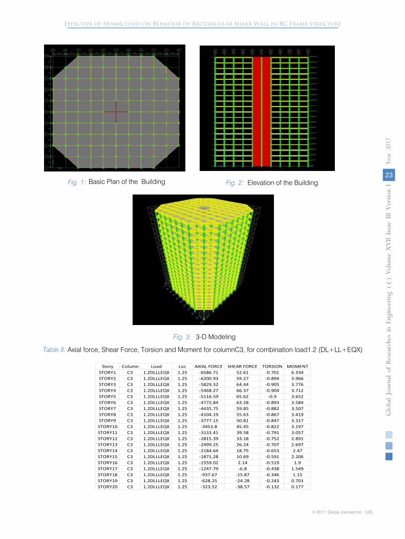
Table II: Axial force, Shear Force, Torsion and Moment for columnC3, for combination load1.2 (DL+LL+EQX)
Story Column Load Loc AXIAL FORCE SHEAR FORCE TORSION MOMENTSTORY1 C3 1.2DLLLEQX 1.25 -6586.71 52.61 -0.701 6.334STORY2 C3 1.2DLLLEQX 1.25 -6200.93 59.27 -0.894 3.966STORY3 C3 1.2DLLLEQX 1.25 -5829.32 64.44 -0.905 3.776STORY4 C3 1.2DLLLEQX 1.25 -5468.27 66.37 -0.904 3.712STORY5 C3 1.2DLLLEQX 1.25 -5116.59 65.62 -0.9 3.652STORY6 C3 1.2DLLLEQX 1.25 -4772.84 63.28 -0.893 3.584STORY7 C3 1.2DLLLEQX 1.25 -4435.75 59.85 -0.882 3.507STORY8 C3 1.2DLLLEQX 1.25 -4104.19 55.63 -0.867 3.419STORY9 C3 1.2DLLLEQX 1.25 -3777.15 50.81 -0.847 3.317STORY10 C3 1.2DLLLEQX 1.25 -3453.8 45.45 -0.822 3.197STORY11 C3 1.2DLLLEQX 1.25 -3133.41 39.58 -0.791 3.057STORY12 C3 1.2DLLLEQX 1.25 -2815.39 33.18 -0.752 2.891STORY13 C3 1.2DLLLEQX 1.25 -2499.25 26.24 -0.707 2.697STORY14 C3 1.2DLLLEQX 1.25 -2184.64 18.75 -0.653 2.47STORY15 C3 1.2DLLLEQX 1.25 -1871.28 10.69 -0.591 2.206STORY16 C3 1.2DLLLEQX 1.25 -1559.02 2.14 -0.519 1.9STORY17 C3 1.2DLLLEQX 1.25 -1247.79 -6.8 -0.438 1.549STORY18 C3 1.2DLLLEQX 1.25 -937.67 -15.87 -0.346 1.15STORY19 C3 1.2DLLLEQX 1.25 -628.25 -24.28 -0.243 0.701STORY20 C3 1.2DLLLEQX 1.25 -323.52 -38.57 -0.132 0.177
Fig. 1:

Effective of Seismicload on Behavior of Rectangular Shear Wall in RC Frame structure
© 2017 Global Journals Inc. (US)
Globa
l Jo
urna
l of
Resea
rche
s in E
nginee
ring
(
)Volum
e XVII Issue
III V
ersion
I
24
Year
2017
E
Graph 1: Axial force, Shear Force, Torsion and Moment for column C3
Table III: Axial force, Shear Force, Torsion and Moment for column C8, For combination load1.2(DL+LL+EQX)
Graph 2: Axial force, Shear Force, Torsion and Moment for column C8
Table IV: Axial force, Shear Force, Torsion and Moment for column C11,For combination load1.2(DL+LL+EQX)
Story Column Load Loc AXIAL FORCE SHEAR FORCE TORSION MOMENTSTORY1 C8 1.2DLLLEQX 1.25 -6483.38 70.63 -0.701 6.098STORY2 C8 1.2DLLLEQX 1.25 -6102.03 76.82 -0.894 3.919STORY3 C8 1.2DLLLEQX 1.25 -5738.56 81.5 -0.905 4.626STORY4 C8 1.2DLLLEQX 1.25 -5386.9 83.06 -0.904 5.194STORY5 C8 1.2DLLLEQX 1.25 -5045.42 82.04 -0.9 5.693STORY6 C8 1.2DLLLEQX 1.25 -4712.14 79.47 -0.893 6.085STORY7 C8 1.2DLLLEQX 1.25 -4385.38 75.81 -0.882 6.378STORY8 C8 1.2DLLLEQX 1.25 -4063.7 71.36 -0.867 6.577STORY9 C8 1.2DLLLEQX 1.25 -3745.86 66.25 -0.847 6.686STORY10 C8 1.2DLLLEQX 1.25 -3430.85 60.54 -0.822 6.711STORY11 C8 1.2DLLLEQX 1.25 -3117.82 54.24 -0.791 6.656STORY12 C8 1.2DLLLEQX 1.25 -2806.06 47.31 -0.752 6.525STORY13 C8 1.2DLLLEQX 1.25 -2495.05 39.72 -0.707 6.322STORY14 C8 1.2DLLLEQX 1.25 -2184.39 31.43 -0.653 6.052STORY15 C8 1.2DLLLEQX 1.25 -1873.8 22.44 -0.591 5.718STORY16 C8 1.2DLLLEQX 1.25 -1563.2 12.76 -0.519 5.326STORY17 C8 1.2DLLLEQX 1.25 -1252.59 2.5 -0.438 4.88STORY18 C8 1.2DLLLEQX 1.25 -942.27 -8.14 -0.346 4.393STORY19 C8 1.2DLLLEQX 1.25 -632.04 -18.38 -0.243 3.859STORY20 C8 1.2DLLLEQX 1.25 -326.92 -34.34 -0.132 2.942
Story Column Load Loc AXIAL FORCE SHEAR FORCE TORSION MOMENTSTORY1 C11 1.2DLLLEQX 1.25 -6934.71 55.69 -0.701 4.552STORY2 C11 1.2DLLLEQX 1.25 -6553.17 70.43 -0.894 3.132STORY3 C11 1.2DLLLEQX 1.25 -6175.2 84.53 -0.905 3.318STORY4 C11 1.2DLLLEQX 1.25 -5801.64 93.99 -0.904 3.609STORY5 C11 1.2DLLLEQX 1.25 -5432.62 100.01 -0.9 3.89STORY6 C11 1.2DLLLEQX 1.25 -5068.25 103.61 -0.893 4.153STORY7 C11 1.2DLLLEQX 1.25 -4708.5 105.35 -0.882 4.393STORY8 C11 1.2DLLLEQX 1.25 -4353.24 105.61 -0.867 4.606STORY9 C11 1.2DLLLEQX 1.25 -4002.28 104.62 -0.847 4.788STORY10 C11 1.2DLLLEQX 1.25 -3655.37 102.52 -0.822 4.935STORY11 C11 1.2DLLLEQX 1.25 -3312.23 99.38 -0.791 5.045STORY12 C11 1.2DLLLEQX 1.25 -2972.55 95.27 -0.752 5.114STORY13 C11 1.2DLLLEQX 1.25 -2636.01 90.21 -0.707 5.14STORY14 C11 1.2DLLLEQX 1.25 -2302.29 84.25 -0.653 5.12STORY15 C11 1.2DLLLEQX 1.25 -1971.05 77.46 -0.591 5.052STORY16 C11 1.2DLLLEQX 1.25 -1641.95 69.92 -0.519 4.934STORY17 C11 1.2DLLLEQX 1.25 -1314.64 61.83 -0.438 4.764STORY18 C11 1.2DLLLEQX 1.25 -988.78 53.48 -0.346 4.534STORY19 C11 1.2DLLLEQX 1.25 -663.86 45.12 -0.243 4.324STORY20 C11 1.2DLLLEQX 1.25 -341.55 41.25 -0.132 3.098

Effective of Seismicload on Behavior of Rectangular Shear Wall in RC Frame structure
© 2017 Global Journals Inc. (US)
Globa
l Jo
urna
l of
Resea
rche
s in E
nginee
ring
(
)Volum
e XVII Issue
III V
ersion
I
25
Year
2017
E
Graph 3: Axial force, Shear Force, Torsion and Moment for column C11
Table V: Axial force, Shear Force, Torsion and Moment for column C14, for combination load1.2 (DL+LL+EQX)
Graph 4: Axial force, Shear Force, Torsion and Moment for column C14
Table VI: Axial force, Shear Force, Torsion and Moment for column C3, for combination load1.2 (DL+LL+EQY)
Story Column Load Loc AXIAL FORCE SHEAR FORCE TORSION MOMENTSTORY1 C14 1.2DLLLEQX 1.25 -6783.79 68.36 -0.701 5.024STORY2 C14 1.2DLLLEQX 1.25 -6402.91 86.42 -0.894 2.786STORY3 C14 1.2DLLLEQX 1.25 -6026.73 103.62 -0.905 2.16STORY4 C14 1.2DLLLEQX 1.25 -5656.24 116.05 -0.904 1.645STORY5 C14 1.2DLLLEQX 1.25 -5291.65 124.87 -0.9 1.14STORY6 C14 1.2DLLLEQX 1.25 -4932.95 131.05 -0.893 0.644STORY7 C14 1.2DLLLEQX 1.25 -4579.98 135.11 -0.882 0.16STORY8 C14 1.2DLLLEQX 1.25 -4232.4 137.42 -0.867 -0.311STORY9 C14 1.2DLLLEQX 1.25 -3889.84 138.19 -0.847 -0.769STORY10 C14 1.2DLLLEQX 1.25 -3551.85 137.55 -0.822 -1.214STORY11 C14 1.2DLLLEQX 1.25 -3217.98 135.59 -0.791 -1.647STORY12 C14 1.2DLLLEQX 1.25 -2887.78 132.36 -0.752 -2.069STORY13 C14 1.2DLLLEQX 1.25 -2560.83 127.9 -0.707 -2.484STORY14 C14 1.2DLLLEQX 1.25 -2236.72 122.26 -0.653 -2.894STORY15 C14 1.2DLLLEQX 1.25 -1915.07 115.51 -0.591 -3.302STORY16 C14 1.2DLLLEQX 1.25 -1595.53 107.77 -0.519 -3.712STORY17 C14 1.2DLLLEQX 1.25 -1277.79 99.22 -0.438 -4.128STORY18 C14 1.2DLLLEQX 1.25 -961.52 90.17 -0.346 -4.537STORY19 C14 1.2DLLLEQX 1.25 -646.26 80.65 -0.243 -5.113STORY20 C14 1.2DLLLEQX 1.25 -333.95 79.49 -0.132 -3.98
Story Column Load Loc AXIAL FORCE SHEAR FORCE TORSION MOMENTSTORY1 C3 1.2DLLLEQY 1.25 -6800.3 4.62 0.699 22.041STORY2 C3 1.2DLLLEQY 1.25 -6418.46 -1.51 0.888 18.985STORY3 C3 1.2DLLLEQY 1.25 -6047 -7.82 0.899 21.631STORY4 C3 1.2DLLLEQY 1.25 -5683.41 -13.23 0.898 23.242STORY5 C3 1.2DLLLEQY 1.25 -5326.54 -18.08 0.894 24.182STORY6 C3 1.2DLLLEQY 1.25 -4975.29 -22.37 0.887 24.671STORY7 C3 1.2DLLLEQY 1.25 -4628.75 -26.18 0.876 24.792STORY8 C3 1.2DLLLEQY 1.25 -4286.17 -29.55 0.861 24.613STORY9 C3 1.2DLLLEQY 1.25 -3946.92 -32.55 0.841 24.169STORY10 C3 1.2DLLLEQY 1.25 -3610.48 -35.22 0.816 23.484STORY11 C3 1.2DLLLEQY 1.25 -3276.39 -37.61 0.784 22.572STORY12 C3 1.2DLLLEQY 1.25 -2944.31 -39.76 0.746 21.443STORY13 C3 1.2DLLLEQY 1.25 -2613.93 -41.71 0.7 20.104STORY14 C3 1.2DLLLEQY 1.25 -2284.99 -43.49 0.646 18.571STORY15 C3 1.2DLLLEQY 1.25 -1957.31 -45.15 0.584 16.865STORY16 C3 1.2DLLLEQY 1.25 -1630.72 -46.71 0.512 15.021STORY17 C3 1.2DLLLEQY 1.25 -1305.11 -48.21 0.431 13.102STORY18 C3 1.2DLLLEQY 1.25 -980.44 -49.65 0.339 11.198STORY19 C3 1.2DLLLEQY 1.25 -656.24 -50.72 0.236 9.531STORY20 C3 1.2DLLLEQY 1.25 -335.79 -59.21 0.125 6.297

Effective of Seismicload on Behavior of Rectangular Shear Wall in RC Frame structure
© 2017 Global Journals Inc. (US)
Globa
l Jo
urna
l of
Resea
rche
s in E
nginee
ring
(
)Volum
e XVII Issue
III V
ersion
I
26
Year
2017
E
Graph 5: Axial force, Shear Force, Torsion and Moment for column C3
Table VII: Axial force, Shear Force, Torsion and Moment for column C8, For combination load1.2 (DL+LL+EQY)
Graph 6: Axial force, Shear Force, Torsion and Moment for column C8
Table VIII: Axial force, Shear Force, Torsion and Moment for column C11, For combination load1.2(DL+LL+EQY)
Story Column Load Loc AXIAL FORCE SHEAR FORCE TORSION MOMENTSTORY1 C8 1.2DLLLEQY 1.25 -7206.65 -12.14 0.699 22.482STORY2 C8 1.2DLLLEQY 1.25 -6830.45 -15.16 0.888 18.521STORY3 C8 1.2DLLLEQY 1.25 -6457.85 -18.41 0.899 20.64STORY4 C8 1.2DLLLEQY 1.25 -6087.2 -21.12 0.898 21.731STORY5 C8 1.2DLLLEQY 1.25 -5718.21 -23.56 0.894 22.221STORY6 C8 1.2DLLLEQY 1.25 -5350.65 -25.72 0.887 22.322STORY7 C8 1.2DLLLEQY 1.25 -4984.45 -27.66 0.876 22.115STORY8 C8 1.2DLLLEQY 1.25 -4619.6 -29.38 0.861 21.665STORY9 C8 1.2DLLLEQY 1.25 -4256.11 -30.9 0.841 21.004STORY10 C8 1.2DLLLEQY 1.25 -3894.04 -32.25 0.816 20.152STORY11 C8 1.2DLLLEQY 1.25 -3533.42 -33.41 0.784 19.118STORY12 C8 1.2DLLLEQY 1.25 -3174.31 -34.4 0.746 17.909STORY13 C8 1.2DLLLEQY 1.25 -2816.75 -35.21 0.7 16.53STORY14 C8 1.2DLLLEQY 1.25 -2460.74 -35.84 0.646 14.991STORY15 C8 1.2DLLLEQY 1.25 -2106.3 -36.26 0.584 13.309STORY16 C8 1.2DLLLEQY 1.25 -1753.39 -36.47 0.512 11.516STORY17 C8 1.2DLLLEQY 1.25 -1401.92 -36.44 0.431 9.663STORY18 C8 1.2DLLLEQY 1.25 -1051.81 -36.13 0.339 7.851STORY19 C8 1.2DLLLEQY 1.25 -702.51 -35.39 0.236 6.167STORY20 C8 1.2DLLLEQY 1.25 -356.75 -38.38 0.125 3.988
Story Column Load Loc AXIAL FORCE SHEAR FORCE TORSION MOMENTSTORY1 C11 1.2DLLLEQY 1.25 -7019.18 7.49 0.699 23.415STORY2 C11 1.2DLLLEQY 1.25 -6636.78 7.82 0.888 20.128STORY3 C11 1.2DLLLEQY 1.25 -6257.96 8 0.899 23.039STORY4 C11 1.2DLLLEQY 1.25 -5883.17 8.11 0.898 24.968STORY5 C11 1.2DLLLEQY 1.25 -5512.48 8.2 0.894 26.213STORY6 C11 1.2DLLLEQY 1.25 -5145.94 8.27 0.887 26.992STORY7 C11 1.2DLLLEQY 1.25 -4783.48 8.33 0.876 27.383STORY8 C11 1.2DLLLEQY 1.25 -4425 8.38 0.861 27.449STORY9 C11 1.2DLLLEQY 1.25 -4070.31 8.41 0.841 27.224STORY10 C11 1.2DLLLEQY 1.25 -3719.21 8.41 0.816 26.731STORY11 C11 1.2DLLLEQY 1.25 -3371.44 8.36 0.784 25.981STORY12 C11 1.2DLLLEQY 1.25 -3026.76 8.26 0.746 24.985STORY13 C11 1.2DLLLEQY 1.25 -2684.87 8.09 0.7 23.751STORY14 C11 1.2DLLLEQY 1.25 -2345.49 7.85 0.646 22.292STORY15 C11 1.2DLLLEQY 1.25 -2008.31 7.51 0.584 20.632STORY16 C11 1.2DLLLEQY 1.25 -1673.02 7.07 0.512 18.807STORY17 C11 1.2DLLLEQY 1.25 -1339.31 6.52 0.431 16.878STORY18 C11 1.2DLLLEQY 1.25 -1006.85 5.84 0.339 14.932STORY19 C11 1.2DLLLEQY 1.25 -675.19 5.03 0.236 13.272STORY20 C11 1.2DLLLEQY 1.25 -345.76 4.54 0.125 9.105
Effective of Seismicload on Behavior of Rectangular Shear Wall in RC Frame structure
© 2017 Global Journals Inc. (US)
Globa
l Jo
urna
l of
Resea
rche
s in E
nginee
ring
(
)Volum
e XVII Issue
III V
ersion
I
27
Year
2017
E
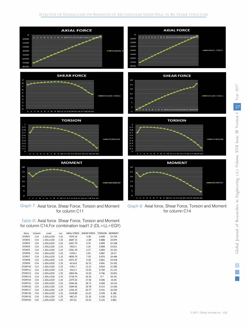
Axial force, Shear Force, Torsion and Moment for column C11
Axial force, Shear Force, Torsion and Moment for column C14
Story Column Load Loc AXIAL FORCE SHEAR FORCE TORSION MOMENTSTORY1 C14 1.2DLLLEQY 1.25 -7070.16 -2.85 0.699 23.743STORY2 C14 1.2DLLLEQY 1.25 -6687.15 -1.09 0.888 19.879STORY3 C14 1.2DLLLEQY 1.25 -6307.79 0.76 0.899 22.248STORY4 C14 1.2DLLLEQY 1.25 -5932.5 2.54 0.898 23.621STORY5 C14 1.2DLLLEQY 1.25 -5561.29 4.27 0.894 24.322STORY6 C14 1.2DLLLEQY 1.25 -5194.1 5.95 0.887 24.57STORY7 C14 1.2DLLLEQY 1.25 -4830.76 7.59 0.876 24.446STORY8 C14 1.2DLLLEQY 1.25 -4471.07 9.18 0.861 24.018STORY9 C14 1.2DLLLEQY 1.25 -4114.8 10.72 0.841 23.322STORY10 C14 1.2DLLLEQY 1.25 -3761.7 12.22 0.816 22.383STORY11 C14 1.2DLLLEQY 1.25 -3411.5 13.65 0.784 21.215STORY12 C14 1.2DLLLEQY 1.25 -3063.94 15.03 0.746 19.831STORY13 C14 1.2DLLLEQY 1.25 -2718.74 16.33 0.7 18.241STORY14 C14 1.2DLLLEQY 1.25 -2375.63 17.56 0.646 16.46STORY15 C14 1.2DLLLEQY 1.25 -2034.36 18.71 0.584 14.513STORY16 C14 1.2DLLLEQY 1.25 -1694.65 19.78 0.512 12.436STORY17 C14 1.2DLLLEQY 1.25 -1356.25 20.77 0.431 10.293STORY18 C14 1.2DLLLEQY 1.25 -1018.89 21.67 0.339 8.186STORY19 C14 1.2DLLLEQY 1.25 -682.23 22.35 0.236 6.223STORY20 C14 1.2DLLLEQY 1.25 -347.61 25.91 0.125 3.862
Graph 7: Graph 8:
Table IX: Axial force Shear Force, Torsion and Moment for column C14,For combination load1.2 (DL+LL+EQY)
Effective of Seismicload on Behavior of Rectangular Shear Wall in RC Frame structure
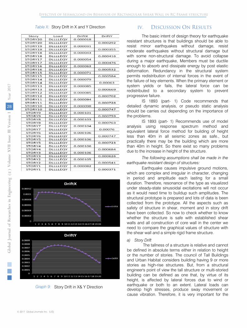
Story Drift in X and Y Direction
Story Drift in X& Y Direction
© 2017 Global Journals Inc. (US)
Globa
l Jo
urna
l of
Resea
rche
s in E
nginee
ring
(
)Volum
e XVII Issue
III V
ersion
I
28
Year
2017
E
IV. DISCUSSION ON RESULTS
The basic intent of design theory for earthquake resistant structures is that buildings should be able to resist minor earthquakes without damage, resist moderate earthquakes without structural damage but with some non-structural damage. To avoid collapse during a major earthquake, Members must be ductile enough to absorb and dissipate energy by post elastic deformation. Redundancy in the structural system permits redistribution of internal forces in the event of the failure of key elements. When the primary element or system yields or fails, the lateral force can be redistributed to a secondary system to prevent progressive failure.
IS 1893 (part- 1) Code recommends that detailed dynamic analysis, or pseudo static analysis should be carries out depending on the importance of the problems.
IS 1893 (part- 1) Recommends use of model analysis using response spectrum method and equivalent lateral force method for building of height less than 40m in all seismic zones as safe., but practically there may be the building which are more than 40m in height. So there exist so many problems due to the increase in height of the structure.
The following assumptions shall be made in the earthquake resistant design of structures:
Earthquake causes impulsive ground motions, which are complex and irregular in character, changing in period and amplitude each lasting for a small duration. Therefore, resonance of the type as visualized under steady-state sinusoidal excitations will not occur as it would need time to buildup such amplitudes. The structural prototype is prepared and lots of data is been collected from the prototype. All the aspects such as safety of structure in shear, moment and in story drift have been collected. So now to check whether to know whether the structure is safe with established shear walls and all construction of core wall in the center we need to compare the graphical values of structure with the shear wall and a simple rigid frame structure.
a) Story DriftThe tallness of a structure is relative and cannot
be defined in absolute terms either in relation to height or the number of stories. The council of Tall Buildings and Urban Habitat considers building having 9 or more stories as high-rise structures. But, from a structural engineer's point of view the tall structure or multi-storied building can be defined as one that, by virtue of its height, is affected by lateral forces due to wind or earthquake or both to an extent. Lateral loads can develop high stresses, produce sway movement or cause vibration. Therefore, it is very important for the
Table X:
Graph 9:
structure to have sufficient strength against vertical loads together with adequate stiffness to resist lateral forces. So lateral forces due to wind or seismic loading must be considered for tall building design along with gravity forces vertical loads. Tall and slender buildings are strongly wind sensitive and wind forces are applied to the exposed surfaces of the building, whereas seismic forces are inertial (body forces), which result from the distortion of the ground and the inertial resistance of the building. These forces cause horizontal
deflection is the predicted movement of a structure under lateral loads and story drift is defined as the difference in lateral deflection between two adjacent stories. Lateral deflection and drift have three effects on a structure; the movement can affect the structural elements (such as beams and columns); the movements can affect non-structural elements (such as the windows and cladding); and the movements can affect adjacent structures. Without proper consideration during the design process, large deflections and drifts can have adverse effects on structural elements, nonstructural elements, and adjacent structures.
When the initial sizes of the frame members have been selected, an approximate check on the horizontal drift of the structures can be made. The drift in the non-slender rigid frame is mainly caused by racking. This racking may be considered as comprising two components: the first is due to rotation of the joints, as allowed by the double bending of the girders, while the second is caused by double bending of the columns. If the rigid frame is slender, a contribution to drift caused by the overall bending of the frame, resulting from axial deformations of the columns, may be significant. If the frame has height width ratio less than 4:1, the contribution of overall bending to the total drift at the top of the structure is usually less than 10% of that due to racking. The following method of calculation for drift allows the separate determination of the components attributable to beam bending, and overall cantilever action. Drift problem as the horizontal displacement of all tall buildings is one of the most serious issues in tall building design, relating to the dynamic characteristics of the building during earthquakes and strong winds. Drift shall be caused by the accumulated deformations of each member, such as a beam, column and shear wall. In this study analysis is done with changing structural parameters to observe the effect on the drift (lateral deflection) of the tall building due to earthquake loading.
IS 1893 Part 1 Codal
Provoisions for Storey Drift Limitations
The storey drift in any storey due to the minimum specified design lateral force, with partial load factor of 1.0, shall not exceed 0.004 times the storey height For the purposes of displacement requirements
only, it is permissible to use seismic force obtained from the computed fundamental period (T) of the building without the lower bound limit on design seismic force
Effective of Seismicload on Behavior of Rectangular Shear Wall in RC Frame structure
© 2017 Global Journals Inc. (US)
Globa
l Jo
urna
l of
Resea
rche
s in E
nginee
ring
(
)Volum
e XVII Issue
III V
ersion
I
29
Year
2017
E
specified in dynamic analysis. The tallness of a structure is relative and cannot be defined in absolute terms either in relation to height or the number of stories.
V. Conclusion
It is evident from the observing result that the shear wall should be near to center of mass and center of rigidity of structure.
Shear walls must provide the necessary lateral strength to resist horizontal earthquake forces.
When shear walls are strong enough, they will transfer these horizontal forces to the next element in the load path below them, such as other shear walls, floors, foundation walls, slabs or footings.
For the columns located away from the shear wall the Bending Moment is high and shear force is less when compared with the columns connected to the shear wall.
Shear walls also provide lateral stiffness to prevent the roof or floor above from excessive side-sway.
When shear walls are stiff enough, they will prevent floor and roof framing members from moving off their supports. Also, buildings that are sufficiently stiff will usually suffer less nonstructural damage.
The vertical reinforcement that is uniformly distributed in the shear wall shall not be less than the horizontal reinforcement. This provision is particularly for squat walls (i.e. Height-to-width ratio is about 1.0). However, for walls whit height-to-width ratio less than 1.0, a major part of the shear force is resisted by the vertical reinforcement. Hence,
It is evident from the observing result that the shear wall are making value of torsion very low.
Based on the analysis and discussion, shear wall are very much suitable for resisting earthquake induced lateral forces in multistoried structural systems when compared to multistoried structural systems whit out shear walls. They can be made to behave in a ductile manner by adopting proper detailing techniques.
It is evident from the observing result that for combination loads 1.2 (DLLLEQX) & 1.2 (DLLLEQY) maximum value of moment at story one and minimum value of shear force also at story one. The Moment is maximum when the shear force is minimum or changes sign.
The story drift for the combination load(DL+LL+EQY) in X & Y direction shown different performance and less value for story drift in all combinations at story 20.The value of story drift is very low because of adding shear walls to the building.
adequate vertical reinforcement should be provided for such walls.
References
Références Referencias
1.
Chopra, A.K., “Dynamics of Structures: Theory and Application to Earthquake Engineering”, Pearson Education, 4th edition, 2012.
2.
Duggal, S.K., “Earthquake Resistant Design of Structures” Oxford University
Press, New Delhi 2010
3.
Bureau of Indian Standars, IS 456: 2000, “Plain and Reinforced Concrete-Code of practice”, New Delhi, India.
4.
Bureau
of Indian Standards: IS 13920: 1993, “Ductile detailing of reinforced concrete structures subjected to seismic forces-Code of Practice”, New Delhi, India.
5.
Bureau of Indian Standards: IS 875( part 1): 1987, “Dead loads on buildings and Structures”, New Delhi, India.
6.
Bureau of Indian Standards: IS 875( part 2 ): 1987, “Live loads on buildings and Structures”,
New Delhi, India.
7.
Bureau of Indian Standards: IS 1893 (part 1): 2002, “Criteria for earthquake resistant design of structures: Part 1 General provisions and buildings”, New Delhi, India.
8.
Ashraf, M., Siddiqi, Z.A., Javed, M.A., “Configuration of a multi-story building subjected to lateral forces”, Asian journal of civil engineering, Vol. 9, No. 5, pp. 525-537, 2008.
9.
Chandurkar, P.P., Dr. Pajgade, P.S., “Seismic analysis of RCC building with and without shear wall”, International Journal of Modern Engineering Research. Vol. 3, Issue 3, pp. 1805-1810, 2013.
10.
Prajapati, R.J.,
Patel, V.R., “ Effect of different position of shear wall on deflection in high rise building” , ISSN: 22311963, International Journal of Advances in Engineering & Technology, September 2013.
11.
Rahangdale, H., Satone, S.R., “Design and analysis of multi-storied building with effect of shear wall”, International journal of engineering research and application", Vol. 3, Issue 3, pp. 223-232, 2013.
12.
Shrestha, M., “Effects Of Openings In Shear Wall On Seismic Response Of Frame-Shear Wall Structures”, M.E. Thesis, Graduate School, Kasetsart University, 2008.
Effective of Seismicload on Behavior of Rectangular Shear Wall in RC Frame structure
© 2017 Global Journals Inc. (US)
Globa
l Jo
urna
l of
Resea
rche
s in E
nginee
ring
(
)Volum
e XVII Issue
III V
ersion
I
30
Year
2017
E