effective sectional area 30 mm - content.smcetech.com
TRANSCRIPT

CAT.EUS50-20 -UKB
Blow Gun
Series VMG
Special valve design and construction saves energyReduced pressure drop due to smooth flow of fluid
Conventional construction
PAT.PEND
Series VMG
<Dark blue>Bottom piping
<White>Top piping
Pressure loss is less than 1%.
(Nozzle size: ø2.5)
Effective sectional area
30 mm2

Piping direction
Bottom
Top
Body colour
White
Dark blue
Piping type
With S coupler(quick connect) plug
Rc, NPT, G 1/4, 3/8
Nozzle type
Male thread nozzle
Low noise nozzle
High efficiency nozzle
Copper extension nozzle
Pressure loss
0 1.0
Conventional product
Op
erat
ion
al f
orc
e
Supply pressure (MPa)
Larg
eS
mal
l
Blow Gun
0
0.01
0.02
0.03
0.04
0.05
0 0.2 0.4 0.6 0.8 1 1.2Supply pressure (MPa)
Pre
ssu
re lo
ss (
MP
a)
∗ Male thread nozzle ø2.5
0.005 MPa pressure loss at 0.5 MPa
Top piping
Bottom pipingWith S coupler plug
Provides constant operational force irrespective of the supply pressure
Features 1
Male threadnozzle
High efficiency nozzle
0.05 0.1 0.15 0.2Internal pressure (MPa)
Th
rust
(g)
15
10
5
0
20
25
30
35
40
45
100 mm
Sample
Scale: Accuracy Measurement value ±0.2% or less
Temperature: 20°C
Distance between a sample and the scale: 100 mm
High efficiency nozzleAir blow thrust has been increased by 10%. (comparison with nozzles of the same diameter)

Example of Improvement
Filterregulator
S couplerCoiltube
S2
S1
ø2Nozzle
ø2
Effective area ratio10.7 : 1
After Improvement
Before Improvement
Pressure loss
Change to fittings, tubing and Blow Gun with large effective areas.
S2
S1
ø3
Upstream side S1: 15 Nozzle side S2: 6.4
S1 : S2 = 2.3 : 1ø31
0.700 MPa0.300 MPa0.260 MPa
0.040 MPa
Upstream side S1: 30 Nozzle side S2: 2.8
S1 : S2 = 10.7 : 1ø21
0.700 MPa0.300 MPa0.297 MPa
0.003 MPa
Effective area (mm2)
Effective area ratioNozzle size (mm)Number of nozzlesSupply pressureRegulator pressureOutlet pressurePressure loss
Without nozzleø3
In the case of air guns, energy saving measures are not considered.
Pressure loss
Effect of Energy Saving Improvement
Nozzle: Series KN⋅⋅⋅⋅⋅⋅⋅⋅⋅⋅⋅⋅⋅⋅⋅⋅⋅⋅⋅⋅⋅⋅⋅⋅⋅Page 4S Coupler: Series KK ⋅⋅⋅⋅⋅⋅⋅⋅⋅⋅⋅⋅⋅⋅⋅⋅⋅⋅⋅⋅Page 5S Coupler: Series KKH ⋅⋅⋅⋅⋅⋅⋅⋅⋅⋅⋅⋅⋅⋅⋅⋅⋅⋅Page 7
Regulator: Series AR ⋅⋅⋅⋅⋅⋅⋅⋅⋅⋅⋅⋅⋅⋅⋅⋅⋅⋅⋅⋅⋅Page 8Filter Regulator: Series AW⋅⋅⋅⋅⋅⋅⋅⋅⋅⋅⋅⋅⋅Page 9
Related Products:
Pressure Loss of Air Gun Only
Pressure Loss of Blow Gun Only
Effective area ratio2.3 : 1
Large
Pressure loss Small
Effective area (mm2)
Effective area ratioNozzle size (mm)Number of nozzlesSupply pressureRegulator pressureOutlet pressurePressure loss
Min. 90%ReductionMin. 90%Reduction
Before After
S2Upstream side SI
S2Upstream side SI
e.g.0,04MPa
e.g.0,003MPa
Features 2

Series VMGBlow Gun
Blow gun Nozzle
-01 02 03 04 11 12 13 21 22 23 24 31 32 33 34
Type Nozzle modelWithout nozzleKN-R02-100KN-R02-150 KN-R02-200 KN-R02-250
KNH-R02-100 KNH-R02-150 KNH-R02-200
KNS-R02-075-4KNS-R02-090-8KNS-R02-100-4KNS-R02-110-8
KNL3-06-150KNL3-06-200KNL6-06-150KNL6-06-200
ø1 ø1.5ø2
ø2.5 ø1
ø1.5 ø2
ø0.75 x 4 ø0.9 x 8 ø1 x 4
ø1.1 x 8ø1.5 ø2
ø1.5 ø2
Nozzle size
How to Order
VMG 1
Series
Piping entry
Body colour
Piping connection type
1 03 01W
1 Resin body lever type
1 BottomTop2
Standard type
W WhiteDark blueBU
-NF
RcNPT
G
Connection size
02 03 11
Piping connection system
Screw-in type
With S coupler plug
Port size
Plug part no.
Size and part no.1/43/8
KK4P-02MSNote 1)
Male thread nozzle
High efficiency nozzle
Low noise nozzle with male thread
Copper extensionnozzle
Length 300 mm
Length 600 mm
Specifications
Fluid
Operating pressure range
Proof pressure
Ambient and fluid temperature
Effective area
Port size
Piping entry
Nozzle port size
Weight
Operational force (when the valve is fully open)
Air
0 to 1.0 MPa
1.5 MPa
�5 to 60�C (With no condensation)
30 mm2 (without nozzle)
Rc, NPT, G 1/4, 3/8
Rc 1/4
180 g
7 N
Bottom Top
Note 1)
Note 1) One piece of H06-02 self-align fitting is attached.When a copper extension nozzle is ordered separately, a self-align fitting will also be required for connection. Order one with the above part number in addition to the nozzle.
Note 1) In the case of a type with an S coupler plug, specify no symbol (Rc) for the piping connection type. The size is Rc 1/4.
1
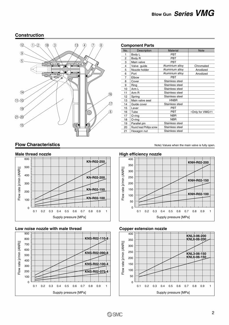
Construction
Flow Characteristics
No.123456789
101112131415161718192021
Body LBody RMain valveValve guideNozzle holderPortElbowCoverRingArm LArm RSpringMain valve sealGuide coverLeverTubeO-ringO-ringParallel pinRound head Phillips screwHexagon nut
MaterialDescription
ChromatedAnodizedAnodized
∗Only for VMG11
PBTPBTPBT
Aluminium alloyAluminium alloyAluminium alloy
PBTStainless steelStainless steelStainless steelStainless steelStainless steel
HNBRStainless steel
PBTPBTNBRNBR
Stainless steelStainless steelStainless steel
Note
Component Parts
600
500
400
300
200
100
00.1 0.2 0.3 0.4 0.5 0.6 0.7 0.8 0.9 1
KN-R02-250
KN-R02-200
KN-R02-100
400
350
300
250
200
150
100
50
00.1 0.2 0.3 0.4 0.5 0.6 0.7 0.8 0.9 1
KNH-R02-200
KNH-R02-150
KNH-R02-100
400
350
300
250
200
150
100
50
00.1 0.2 0.3 0.4 0.5 0.6 0.7 0.8 0.9 1
KNL3-06-200
KNL3-06-150
KNL6-06-200
KNL6-06-150
900
800
700
600
500
400
300
200
100
00.1 0.2 0.3 0.4 0.5 0.6 0.7 0.8 0.9 1
KNS-R02-110-8
KNS-R02-090-8
KNS-R02-100-4
KNS-R02-075-4
Supply pressure [MPa]
Flo
w r
ate
[l/m
in (
AN
R)]
Supply pressure [MPa]
Flo
w r
ate
[l/m
in (
AN
R)]
Supply pressure [MPa]
Flo
w r
ate
[l/m
in (
AN
R)]
Supply pressure [MPa]
Flo
w r
ate
[l/m
in (
AN
R)]
Male thread nozzle High efficiency nozzle
Low noise nozzle with male thread Copper extension nozzle
KN-R02-150
Note) Values when the main valve is fully open.
i
y
ureq w
o
t
!3!8!2
!7
!4
!1 !0
!9
@1 @0
!5
!6
2
Blow Gun Series VMG

Dimensions
23
23
A
172.
5
34.2
30
147
117.5
102
A
30
156
117.5
102
Rc, NPT, G 1/4, 3/8
Width across flats 22
Rc, NPT, G 1/4, 3/8
Width across flats 22
VMG12/Piping entry: Top
VMG11/Piping entry: Bottom
S coupler plug mounting
Rc 1/4
Rc 1/4
Type Nozzle modelKNS-R02-075-4KNS-R02-090-8KNS-R02-100-4KNS-R02-110-8
KNL3-06-150KNL3-06-200KNL6-06-150KNL6-06-200
Low noise nozzle with male thread
Copper extension nozzle (with self-align fitting H06-02)
Nozzle sizeø0.75 x 4 ø0.9 x 8 ø1 x 4
ø1.1 x 8ø1.5 ø2
ø1.5 ø2
A12 12 12 12
305.3 305.3 605.3 605.3
Type Nozzle modelKN-R02-100KN-R02-150 KN-R02-200 KN-R02-250
KNH-R02-100 KNH-R02-150 KNH-R02-200
Male thread nozzle
High efficiency nozzle
Nozzle sizeø1
ø1.5ø2
ø2.5 ø1
ø1.5 ø2
Note 1) Note 1)A23.4 23
22.5 22.1 44 44 44
34.2
Not
e 1)
Note 1) Reference dimensions after installation
(mm) (mm)
Nozzle
Nozzle
Not
e 1)
S coupler plug mounting
3
Series VMG

KNL3-06-150KNL3-06-200KNL6-06-150KNL6-06-200
ø1.5ø2ø1.5ø2
ø6ø6ø6ø6
300300600600
Copper extension nozzle: KNL (mm)
Model Nozzle sizeD Outside diameter L1
øD
L1
Out
side
diam
eter
KN-R02-100KN-R02-150KN-R02-200KN-R02-250
ø1ø1.5ø2ø2.5
R 1/4R 1/4R 1/4R 1/4
14141414
31.43130.530.1
25.42524.524.1
Male thread nozzle: KN (mm)
ModelNozzle size
DConnection
thread L1 AWidth across flats
H1
A
L1
øD
H1
Connection thread
Low noise nozzle with male thread: KNS
ModelNozzle size
DConnection
thread L1 AWidth across flats
H1
KNS-R02-075-4KNS-R02-090-8KNS-R02-100-4KNS-R02-110-8
ø0.75 x 4ø0.9 x 8ø1 x 4ø1.1 x 8
R 1/4R 1/4R 1/4R 1/4
14141414
20202020
14141414
(mm)
øD
2
A
L1
Connection threadH1
High efficiency nozzle: KNH
ModelNozzle size
DConnection
thread L1 AWidth across flats
H1
KNH-R02-100KNH-R02-150KNH-R02-200
ø1ø1.5ø2
R 1/4R 1/4R 1/4
141414
525252
464646
(mm)
AL1
øD
H1
Connection thread
Self-align fittings (For copper extension nozzle connection)
Male connectorH06-02
Dimensions: Nozzle/Series KN
Air blow thrust has beenincreased by 10%.
Note) When a copper extension nozzle is ordered separately, a self-align fitting will also be required for connection with the blow gun. Order one with the following part number in addition to the nozzle.
4
Blow Gun Series VMG

Fluid
Operating pressure range
Proof pressure
Ambient and fluid temperature
Plating, Sealant
Air, Water (standard industrial water)
0 to 1.0 MPa
1.5 MPa
Air: –5 to 60°C Water: 5 to 40°C
Electroless nickel plated (copper-free application), With male thread sealant
Specifications
Plug and socket connection
Check valve
Sleeve lock mechanism
One-touch connection and release
Socket: Built-in check valve (standard)
Locking manual type (standard)
Performance
Body size
1/4
Plug
KK4P-02MS
Socket
KK4S-02MS
Effective area mm2
39
Effective Area
Large effective areasLight weight
JIS Symbol
Single plug Single socket
Connected plug and socket
Related Products: S Coupler
Series KK
Together with a reduction of the body size, pressing parts and resin parts are used to achieve an overall weight reduction.
� Light weight
Low leakage seal constructionReliable sealing is achieved by surface contact.
Employs a unique connection methodA slim body design and large effective area areachieved with a construction that does not usesteel balls and therefore does not restrict theflow path.
Sleeve cover(Except for Series KK2)
Lock ringShock absorbent PBT
No spring located in the flow pathLoss of effective area is minimised becausethere is no valve spring to block the flow path.
Check valve end configurationfacilitates rectifying effectAllows smooth flow of fluids.
The pulling strength for the plugs and sockets has been improved.We standardised the product with a sleeve cover. Changing the lock ring material to a shockabsorbing PBT further improved the shock absorbent performance.
PAT.
5

Male thread type
1/4 KK4P-02MS
Part no.Body size Port size
Male thread type
Plug (P) Socket (S)
1/4
KK4S-02MS
-03MS
-04MS
Part no.Body size Port size
1 4R
Female thread type
1/4KK4S-02F
-03F
Part no.Body size Port size
1 4
3 8
Rc
Rc
3 8
1 2
1 4R
R
R
1/4KK4S-80N
-85N
Part no.Body sizeApplicable hose
I.D./O.D. mm
Nut fitting type (for fiber reinforced urethane hose)
8/12
8.5/12.5
Straight type with One-touch fitting
1/410
12
KK4S-10H
-12H
Part no.Body sizeApplicable
tubing O.D. mm
Elbow type with One-touch fitting
1/410
12
KK4S-10L
-12L
Part no.Body sizeApplicable
tubing O.D. mm
6
Blow Gun Series KK

PAT.
Fluid
Operating pressure range
Proof pressure
Ambient and fluid temperature
Plating, Sealant
Connection plug
Air, Water (standard industrial water)
0 to 1.0 MPa
1.5 MPa
Air: –5 to 60°C Water: 5 to 40°C
Electroless nickel plated (copper-free application), With male thread sealant
Series KK plug
Specifications
Plug and socket connection
Check valve
Sleeve lock mechanism
One-touch connection and release
Socket: Built-in check valve (standard)
None
Performance
Body size
1/4
Plug
KK4P-02MS
Socket
KKH4S-02MS
Effective area mm2
39
Effective Area
The flow is the same since the internal parts use the common parts as the circle-shaped standard products.
� A rubber cover and a super high impact absorbent PBT resin are used in the body’s outer edge to absorb impact from a drop which is equiva-lent to 0.5 J impact energy.
� The flow is equivalent to the conventional models (Series KK).
� The pulling strength for the plugs and sockets has been improved. Twice as strong as the conventional models.
JIS Symbol Socket (S)
Male thread type
1/4
KKH4S-02MS
-03MS
-04MS
Part no.Body size Port size
1/4KKH4S-80N
-85N
Part no.Body size
Female thread type
1/4KKH4S-02F
-03F
Part no.Body size Port size
Nut fitting type (for fiber reinforced urethane hose)
Applicable hoseI.D./O.D. mm
1 4
3 8
R
R
3 8
1 2
1 4R
R
R
Series KKH are only available as sockets.
Series KK should be used as plugs.
8/12
8.5/12.5
Related Products: S Coupler
Series KKH
Cover ring(Super high impact PBT)Spacer
(High impact PBT)
Sleeve cover(Rubber)
Single plug Single socket
Connected plug and socket
7

Body size
Related Products: Regulator
Series AR30 to 60
Standard Specifications
How to Order
Port sizeFluidProof pressureMaximum operating pressureRegulating pressure rangeGauge port sizeRelief pressureAmbient and fluid temperatureConstructionWeight (kg)
AR40
0.44
AR40-06
Air1.5 MPa1.0 MPa
0.05 to 0.85 MPa
Set pressure + 0.05 MPa (at relief flow rate of 0.1 l/min (ANR))�5 to 60�C (With no condensation)
Relieving type0.47
AR50
1.17
AR601
1.22
Applicable model
Accessory
Bracket assembly
Set nut
Pressuregauge
Round typeSquare embedded type
Round typeSquare embedded type
1.0 MPa
0.2 MPa
AR30
AR30P-270AS
AR30P-260S
G36-10-�01
GC3-10AS
G36-2-�01
GC3-2AS
AR40
AR40P-270AS
AR40P-260S
G46-10-�02
GC3-10AS
G46-2-�02
GC3-2AS
AR40-06
AR40P-270AS
AR40P-260S
G46-10-�02
GC3-10AS
G46-2-�02
GC3-2AS
AR50
AR50P-270AS
�
AR60
AR50P-270AS
�
G46-10-�02
GC3-10AS
G46-2-�02
GC3-2AS
G46-10-�02
GC3-10AS
G46-2-�02
GC3-2AS
Accessory Part No.
Note 1) Assembly includes a bracket and set nuts.Note 2) � in part numbers for a round type pressure gauge indicates a type of connection threads. No indication is necessary for R; however,
indicate and N for NPT. Contact SMC for regarding the connection thread NPT and pressure gauge supply for PSI unit specifications.Note 3) Includes one O-ring and 2 mounting screws.Note 4) Assembly includes a bracket and 2 mounting screws.Note 5) Contact SMC regarding the set nuts for AR50 and AR60.
Note 1) The type with square embedded pressure gauge does not have connection threads.
AR 30 BEF 1N03
Regulator
Thread typePort size
Option
30405060
0203040610
NF
-Metric thread
(M5)
RcNPT
G
Accessory/Optional Combinations
Accessory/Optional specifications
Combination
With bracket (with set nut)
Square embedded type pressure gauge
Round type pressure gauge
With set nut (for panel mount)
0.02 to 0.2 MPa setting
Non-relieving type
Flow direction: Right � LeftDisplay units for product nameplate and pressure gauge: PSI, °F
Accessory Option ApplicableregulatorSymbol
BEGH –1 –N –R
–Z
B E G H 1 N R Z AR30 to 60
Accessory
AR30
0.29
AR30
JIS Symbol
1
1 23 4
3 8
1
1 2
1 4
3 4
3 8
Symbol
1NRZ
0.02 to 0.2 MPa settingNon-relievingFlow direction: Right � LeftDisplay units for product name plate and pressure gauge: PSI, �F
Applicable modelAR30 to 60AR30 to 60AR30 to 60AR30 to 60
When more than one specification is required, indicate in ascending alphanumeric order.Note 3) The only difference from the standard specifications is the adjusting spring
for the regulator. It does not restrict the setting of 0.2 MPa or more.Note 4) For M5 and NPT thread types. Under the New Measurement Law, the product
is only sold outside Japan. (The SI unit is used inside Japan.)
Note 3)
Note 4)
Note 1) Bracket assembly is not mounted at the time of shipment, but rather packaged together with the regulator for shipment.
Note 2) Mounting threads pressure gauge: AR30�1/8; AR40 to 60�1/4. Pressure gauge is not mounted at the time of shipment, but rather packaged together with the regulator for shipment.
Symbol
-BEGH
Applicable model�
AR30 to 60AR30 to 60AR30 to 60AR30 to 40
Contents�
With bracketWith square embedded type pressure gauge (with limit indicator)
Round type pressure gauge (with limit indicator)With set nut (for panel mount)
Note 1)
Note 2)
: Combination available : Combination not available: Varies depending on a model : Available only with NPT thread
Op
tio
nA
cces
sory
1 4 3 8, 1 21 4 3 8, , 43 3 4 1,
1 41 8 1 4 1 4 1 4
Model
Note 1)
Note 2)Note 3)
Note 4)
Note 5)
Note 4)
Note 5)
Note 3)
Contents
8

Related Products: Filter Regulator
Series AW30/40Integration of a filter and regu-lator allows simple wiring.
AW40
Combination
03 BE30 1NAW FOption
Accessory
Port size
Body size
Thread type
Filterregulator
Nil
0.02 to 0.2 MPa settingMetal bowlNylon bowlMetal bowl with level gaugeDrain guide 1/4Non-relievingFlow direction: Right � LeftDrain cock with barb fitting: ø6 x ø4 nylon tubeDisplay units for product name plate, caution plate for bowl, and pressure gauge: PSI, �F
Applicable modelAW30/40AW30/40AW30/40AW30/40AW30/40AW30/40AW30/40AW30/40AW30/40
Metric thread (M5)
RcNPT
G
30 40
1268JNRWZ
Acc
esso
ryO
pti
on
With bracket (with set nut)Float type auto-drain (N.C.)Float type auto-drain (N.O.)Square embedded type pressure gaugeRound pressure gaugePanel mount (with set nut)0.02 to 0.2 MPa settingMetal bowlNylon bowlMetal bowl with level gaugeWith bowl guardDrain guide 1/4Non-relieving typeFlow direction: Right � LeftDrain cock with barb fitting: ø6 x ø4 nylon tubingDisplay units for product name plate, caution plate for bowl, and pressure gauge: PSI, °F
B C D E G P 1 2 6 8 C J N R W ZOption Applicable filter regulator
AW30/40Accessory
Symbol
BCDE G P –1 –2–6–8–C–J–N–R–W–Z
B CDEG P
With bracketFloat type auto-drain (N.C)Float type auto-drain (N.O)With square embedded type pressure gauge (with limit indicator)With round type pressure gauge (with limit indicator)Panel mount (with set nut)
Applicable model—
AW30/40AW30/40AW30/40AW30/40AW30/40AW30/40
Note 1)
Note 2)
Drain guide is NPT1/4 (applicable to AW30 and 40), and the exhaust port for auto-drain comes with ø3/8" One-touch fit-ting (applicable to AW30 and 40).Drain guide is G1/4 (ap-plicable to AW30 and 40).
When more than one specification is required, indicate in ascending alphabetical order.Note 5) The only difference from the standard specifications is the adjusting spring for the
regulator. It does not restrict the setting of 0.2 MPa or more.Note 6) Without valve function.Note 7) For M5 and NPT thread types. Under the New Measurement Law, this type is only
sold outside Japan. (The SI unit is used inside Japan.)
Note 3) Bracket assembly is not mounted at the time of shipment, but rather packaged together with the filter regulator for shipment.
Note 4) Mounting thread for pressure gauge: AW30—1/8; AR40—1/4. Pressure gauge is not mounted at the time of shipment, but rather packaged together with the regulator for shipment.
NF
ModelPort sizeFluidProof pressureMaximum operating pressureRegulating pressure rangePressure gauge port sizeRelief pressureAmbient and fluid temperatureNominal filtration ratingDrain capacity (cm3)Bowl materialConstructionWeight (kg) Attachment Bowl guard
AW40-06
45
0.75
�
AW40
45
0.72
�
Standard SpecificationsAW30
25
0.40
�Note 1) The type with square embedded pressure gauge does not have connection threads.
Bracket assembly
Set nut
Pressuregauge
Applicable model
1.0 MPa
0.2 MPa
AW40-06AW40AW30
AR30P-270AS
AR30P-260S
G36-10-�01
GC3-10AS
G36-2-�01
GC3-2AS
AD38
AD37
AR40P-270AS
AR40P-260S
G46-10-�02
GC3-10AS
G46-2-�02
GC3-2AS
AD48
AD47
AR40P-270AS
AR40P-260S
G46-10-�02
GC3-10AS
G46-2-�02
GC3-2AS
AD48
AD47
Accessory Part No.
Note 1) Assembly includes a bracket and set nuts.Note 2) � in part numbers of the round type pressure gauge indicates a type
of connection thread. No indication is necessary for R; however, indicate N for NPT. Contact SMC regarding the connection thread NPT and supply of the pressure gauge for PSI unit specifications.
Note 3) Includes one O-ring and 2 mounting screws.Note 4) Minimum operating pressure: N.O. type—0.1 MPa; N.C. type— 0.15
MPa. Contact SMC regarding the specifications for PSI unit and �F.
Air1.5 MPa1.0 MPa
0.05 to 0.85 MPa
Set pressure + 0.05 MPa (at relief flow rate of 0.1 l/min (ANR))�5 to 60�C (With no condensation)
5 µm
PolycarbonateRelieving type
How to Order
ContentsSymbol
SymbolNil
Note 5)
Note 6)
Note 3)
Note 4)
Note 1)
Note 2)
Note 7)
Direct operated type,Relieving type
JIS Symbol
1 2
3 8
02030406
1 4
1 2
3 8
3 4
Accessory/Optional specifications
: Combination available : Combination not available : Varies depending on a model : Available only with NPT thread
1 4 3 8, 1 21 4 3 8, , 43
1 8 1 4 41
Accessory
Round typeSquare embedded type
Round typeSquare embedded type
Note 3)
Note 3)
Float typeauto-drain
N.O.
N.C.
Note 1)
Note 1)
Contents—
Accessory/Optional Combinations
9

These safety instructions are intended to prevent a hazardous situation and/or equipment damage. These instructions indicate the level of potential hazard by labels of "Caution", "Warning" or "Danger". To ensure safety, be sure to observe ISO 4414 Note 1), JIS B 8370 Note 2) and other safety practices.
1. The compatibility of the pneumatic equipment is the responsibility of the person who designs the pneumatic system or decides its specifications.Since the products specified here are used in various operating conditions, their compatibility for the specific pneumatic system must be based on specifications or post analysis and/or tests to meet your specific requirements. The expected performance and safety assurance are the responsibility of the person who has determined the compatibility of the system. This person should continuously review the suitability of all items specified, referring to the latest catalogue information with a view to giving due consideration to any possibility of equipment failure when configuring a system.
2. Only trained personnel should operate pneumatically operated machinery and equipment.Compressed air can be dangerous if handled incorrrectly. Assembly, handling or repair of pneumatic systems should be performed by trained and experienced operators.
3. Do not service machinery/equipment or attempt to remove components until safety is confirmed.1. Inspection and maintenance of machinery/equipment should only be performed once measures to
prevent falling or runaway of the driven objects have been confirmed. 2. When equipment is removed, confirm that safety process as mentioned above. Turn off the supply
pressure for this equipment and exhaust all residual compressed air in the system.3. Before machinery/equipment is restarted, take measures to prevent quick extension of a cylinder
piston rod, etc.
4. Contact SMC if the product will be used in any of the following conditions:1. Conditions and environments beyond the given specifications, or if product is used outdoors.2. Installation on equipment in conjunction with atomic energy, railway, air navigation, vehicles,
medical equipment, food and beverages, recreation equipment, emergency stop circuits, clutch and brake circuits in press applications, or safety equipment.
3. An application which has the possibility of having negative effects on people, property, or animals, requiring special safety analysis.
Note 1) ISO 4414: Pneumatic fluid power--General rules relating to systems.
Note 2) JIS B 8370: General Rules for Pneumatic Equipment
Warning
Caution : Operator error could result in injury or equipment damage.
Warning : Operator error could result in serious injury or loss of life.
Danger : In extreme conditions, there is a possible result of serious injury or loss of life.
Series VMG
Safety Instructions
Back page 1

Nozzle holder
Spanner
Insufficient tightening may cause loosening of the nozzle.
1. Do not apply the blow gun to flammable, explosive or toxic substances such as gas, fuel gas or refrigerant. Such substances may exude from inside the blow gun.
1. Install a stop valve on the supply pressure side of the blow gun to enable emergency shut off in case of unexpected leakage or damage.
2. When installing a nozzle on the blow gun, wrap seal tape around the threads of the nozzle.
3. When installing the nozzle, secure the nozzle holder of the blow gun by applying a spanner of 22 mm width across flats to the two chamfered surfaces of the holder without applying force to the body. Then tighten the nozzle with force within the following torque ranges. As a guideline, it is equivalent to 2 to 3 additional turns with a tool after manual tightening.
1. Confirm the specifications.The products in this catalogue are designed to be used in compressed air systems only. If the products are used in an environment where pressure or temperature is out of the specified range, damage and/or malfunction may result. Do not use under such conditions.
5. Allow extra length when connecting the tube to accommodate changes in tube length due to pressure.
6. Make sure that no twisting, turning or tensile force or moment load is applied to the port or tube. It may cause the fittings to fracture or the tubing to crush, explode or come loose.
7. Do not abrade, entangle or scratch the tubing. It may cause the tubing to crush, explode or come loose.
4. When tightening the threads, secure the nozzle holder of the blow gun by applying a spanner of 22 mm width across flats to the two chamfered surfaces of the holder without applying force to the body. Then tighten the nozzle with torque specified in the table below. As a guideline, it is equivalent to 2 to 3 additional turns using a tool after manual tightening.Be careful that tightening with torque beyond the ranges in the table below may cause damage to the body.
Selection
Mounting
Warning
Warning
Male thread
R 1/4
R 3/8
Tightening torque N⋅m
12 to 14
22 to 24
Nozzle tightening torque range 12 to 14 N �m
Caution
1. Confirm the model, type and size before installation.Also make sure that there is no scratches, gouges or cracks on the product.
2. Before pipingBefore piping, it should be thoroughly blown out with air (flushing) or washed to remove chips, cutting oil and other debris from inside the pipe.
3. Wrapping of pipe tapeWhen screwing together pipes and fittings, etc., be certain that chips from the pipe threads and sealing material do not get inside the piping. Also, when the pipe tape is used, leave 1.5 to 2 thread ridges exposed at the end of the threads.
Piping
Caution
Wrapping direction
Pipe tape
Expose approx. 2 threads
Port
Spanner
Series VMGSpecific Product Precautions 1Be sure to read this and "Precautions for Handling Peumatic Devices" (M-03-E3A) before using.
Back page 2

Hook
1. Do not use in an atmosphere of corrosive gases, chemicals, sea water, water or water vapour or in an environment where such substances may adhere.
2. Provide shading in an environment where the product is exposed to the sunlight.
3. Do not use in an environment where a heat source is at a close distance.
4. Do not use in an environment where static electricity is a problem. It may cause malfunction or failure of the system. Consult with SMC for use in such an environment.
5. Do not use in an environment where spatters are generated. There is danger of fires caused by spattering. Contact SMC for use in such an environment.
6. Do not use in an environment where the product is exposed to cutting oil, lubricant oil or coolant oil. Contact SMC for use in an environment where the product is exposed to such liquid as cutting oil, lubricant oil or coolant oil.
Operating Environment
Warning
1. To prevent lurching of the nozzle due to air pressure, confirm that the nozzle is not loosened or rattling by pulling it by hand before operation.
2. Be sure to wear safety goggles to protect yourself from splashed substances.
3. Do not direct the tip of the nozzle at the face or other parts of a human body. It may cause danger to personnel.
4. Do not use the product to clean or remove toxic substances or chemicals.
5. Do not drop, step on or hit the product. It may cause damage to the product.
6. Do not use the product to disturb public order or public hygiene.
7. This product is not a toy.8. After blowing, be sure to hang the product
on a hook, etc.If leaving the product in a dusty place, particles will enter the product and may result in a malfunction.
Handling
Warning
1. In periodical inspections, check the follow-ing items and replace the parts if necessary.a) Scratches, gouges, abrasion, corrosionb) Air leakagec) Twisting, crushing and turning of connected tubesd) Hardening, deterioration and softening of connected tubese) Loosening of the nozzle
2. When removing the product, first stop the pressure supply, exhaust compressed air in the piping and confirm the condition of atmospheric release.
3. Do not disassemble or remodel the body of the product.
Maintenance
Caution
1. Install air filters.Install air filters at the upstream side of blow gun. The filtration de-gree should be 5 µm or finer.
2. Install an after-cooler, air dryer or water separator, etc.Air excessive drainage may cause malfunction of blow gun and contaminate or damage the target object. To prevent this, install an after-cooler, air dryer or water separator, etc.
1. Use clean air.Do not use compressed air which includes chemicals, synthetic oils containing organic solvents, salt or corrosive gases, etc., as it can cause damage or malfunction.
Air Supply
Warning
Caution
1. Do not lubricate the product. It may contaminate or damage the target object.
Lubrication
Warning
Series VMGSpecific Product Precautions 2Be sure to read this and "Precautions for Handling Peumatic Devices" (M-03-E3A) before using.
Back page 3

SMC CORPORATION 1-16-4 Shimbashi, Minato-ku, Tokio 105 JAPAN; Phone:03-3502-2740 Fax:03-3508-2480Specifications are subject to change without prior notice
and any obligation on the part of the manufacturer.
ARGENTINA, AUSTRALIA, BOLIVIA, BRASIL, CANADA, CHILE,CHINA, HONG KONG, INDIA, INDONESIA, MALAYSIA, MEXICO,NEW ZEALAND, PHILIPPINES, SINGAPORE, SOUTH KOREA,
TAIWAN, THAILAND, USA, VENEZUELA
OTHER SUBSIDIARIES WORLDWIDE:
© DiskArt™ 1988
© DiskArt™ UKSMC Pneumatics (UK) LtdVincent Avenue, Crownhill, Milton Keynes, MK8 0ANPhone: +44 (0)800 1382930 Fax: +44 (0)1908-555064E-mail: [email protected]://www.smcpneumatics.co.uk
AustriaSMC Pneumatik GmbH (Austria).Girakstrasse 8, A-2100 KorneuburgPhone: +43 2262-62280, Fax: +43 2262-62285E-mail: [email protected]://www.smc.at
Czech RepublicSMC Industrial Automation CZ s.r.o.Hudcova 78a, CZ-61200 BrnoPhone: +420 5 414 24611, Fax: +420 5 412 18034E-mail: [email protected]://www.smc.cz
PortugalSMC Sucursal Portugal, S.A.Rua de Engº Ferreira Dias 452, 4100-246 PortoPhone: +351 22-610-89-22, Fax: +351 22-610-89-36E-mail: [email protected]://www.smces.es
BelgiumSMC Pneumatics N.V./S.A.Nijverheidsstraat 20, B-2160 WommelgemPhone: +32 (0)3-355-1464, Fax: +32 (0)3-355-1466E-mail: [email protected]://www.smcpneumatics.be
LithuaniaSMC Pneumatics Lietuva, UABSavanoriu pr. 180, LT-01354 Vilnius, LithuaniaPhone: +370 5 264 81 26, Fax: +370 5 264 81 26
LatviaSMC Pneumatics Latvia SIASmerla 1-705, Riga LV-1006, LatviaPhone: +371 781-77-00, Fax: +371 781-77-01E-mail: [email protected]://www.smclv.lv
SwedenSMC Pneumatics Sweden ABEkhagsvägen 29-31, S-141 71 HuddingePhone: +46 (0)8-603 12 00, Fax: +46 (0)8-603 12 90E-mail: [email protected]://www.smc.nu
FranceSMC Pneumatique, S.A.1, Boulevard de Strasbourg, Parc Gustave EiffelBussy Saint Georges F-77607 Marne La Vallee Cedex 3Phone: +33 (0)1-6476 1000, Fax: +33 (0)1-6476 1010E-mail: [email protected]://www.smc-france.fr
FinlandSMC Pneumatics Finland OYPL72, Tiistinniityntie 4, SF-02031 ESPOOPhone: +358 207 513513, Fax: +358 207 513595E-mail: [email protected]://www.smc.fi
EstoniaSMC Pneumatics Estonia OÜLaki 12-101, 106 21 TallinnPhone: +372 (0)6 593540, Fax: +372 (0)6 593541E-mail: [email protected]://www.smcpneumatics.ee
GreeceS. Parianopoulus S.A.7, Konstantinoupoleos Street, GR-11855 AthensPhone: +30 (0)1-3426076, Fax: +30 (0)1-3455578E-mail: [email protected]://www.smceu.com
TurkeyEntek Pnömatik San. ve Tic Ltd. Sti.Perpa Tic. Merkezi Kat: 11 No: 1625, TR-80270 Okmeydani IstanbulPhone: +90 (0)212-221-1512, Fax: +90 (0)212-221-1519E-mail: [email protected]://www.entek.com.tr
PolandSMC Industrial Automation Polska Sp.z.o.o.ul. Konstruktorska 11A, PL-02-673 Warszawa, Phone: +48 22 548 5085, Fax: +48 22 548 5087E-mail: [email protected]://www.smc.pl
NetherlandsSMC Pneumatics BVDe Ruyterkade 120, NL-1011 AB AmsterdamPhone: +31 (0)20-5318888, Fax: +31 (0)20-5318880E-mail: [email protected]://www.smcpneumatics.nl
IrelandSMC Pneumatics (Ireland) Ltd.2002 Citywest Business Campus, Naas Road, Saggart, Co. DublinPhone: +353 (0)1-403 9000, Fax: +353 (0)1-464-0500E-mail: [email protected]://www.smcpneumatics.ie
HungarySMC Hungary Ipari Automatizálási Kft.Budafoki ut 107-113, H-1117 BudapestPhone: +36 1 371 1343, Fax: +36 1 371 1344E-mail: [email protected]://www.smc-automation.hu
SwitzerlandSMC Pneumatik AGDorfstrasse 7, CH-8484 WeisslingenPhone: +41 (0)52-396-3131, Fax: +41 (0)52-396-3191E-mail: [email protected]://www.smc.ch
ItalySMC Italia S.p.AVia Garibaldi 62, I-20061Carugate, (Milano)Phone: +39 (0)2-92711, Fax: +39 (0)2-9271365E-mail: [email protected]://www.smcitalia.it
GermanySMC Pneumatik GmbHBoschring 13-15, D-63329 EgelsbachPhone: +49 (0)6103-4020, Fax: +49 (0)6103-402139E-mail: [email protected]://www.smc-pneumatik.de
SloveniaSMC industrijska Avtomatika d.o.o.Grajski trg 15, SLO-8360 ZuzemberkPhone: +386 738 85240 Fax: +386 738 85249E-mail: [email protected]://www.smc-ind-avtom.si
SlovakiaSMC Priemyselná Automatizáciá, s.r.o.Námestie Martina Benku 10, SK-81107 BratislavaPhone: +421 2 444 56725, Fax: +421 2 444 56028E-mail: [email protected]://www.smc.sk
RomaniaSMC Romania srlStr Frunzei 29, Sector 2, BucharestPhone: +40 213205111, Fax: +40 213261489E-mail: [email protected]://www.smcromania.ro
NorwaySMC Pneumatics Norway A/SVollsveien 13 C, Granfos Næringspark N-1366 LysakerTel: +47 67 12 90 20, Fax: +47 67 12 90 21E-mail: [email protected]://www.smc-norge.no
DenmarkSMC Pneumatik A/SKnudsminde 4B, DK-8300 OdderPhone: +45 70252900, Fax: +45 70252901E-mail: [email protected]://www.smc-pneumatik.com
RussiaSMC Pneumatik LLC.4B Sverdlovskaja nab, St. Petersburg 195009Phone.:+812 718 5445, Fax:+812 718 5449E-mail: [email protected]://www.smc-pneumatik.ru
SpainSMC España, S.A.Zuazobidea 14, 01015 VitoriaPhone: +34 945-184 100, Fax: +34 945-184 124E-mail: [email protected]://www.smces.es
http://www.smceu.comhttp://www.smcworld.com
EUROPEAN SUBSIDIARIES:
BulgariaSMC Industrial Automation Bulgaria EOOD16 kliment Ohridski Blvd., fl.13 BG-1756 SofiaPhone:+359 2 9744492, Fax:+359 2 9744519E-mail: [email protected]://www.smc.bg
CroatiaSMC Industrijska automatika d.o.o.Crnomerec 12, 10000 ZAGREBPhone: +385 1 377 66 74, Fax: +385 1 377 66 74E-mail: [email protected]://www.smceu.com
1st printing JZ printing JZ 30 UK Printed in Spain