effective wind velocity formula sheet - … · effective wind velocity formula sheet ... ground...
TRANSCRIPT


Phone (309) 566-3000 • Fax (309) 566-3079 • www.rohnnet.com • The Industry Standard
R O O F M O U N T S
252© 2011 ROHN PRODUCTS LLC
RM
E F F E C T I V E W I N D V E L O C I T Y F O R M U L A S H E E T
V = (C1) (C2) (V)e
V = E�ective Wind Velocity at centerline of antenna for calculating required ballast. eC1 = Importance factor coe�cient from Table 1.C2 = Combined exposure and gust e�ect factor coe�cient from Table 2.V = Design ground wind speed for location, per ANSI/TIA-222-G.
Table 1: Values of C1
I Low hazard to human life and/or damage to property, optional services provided. 1.29 0.93II Signi�cant hazard to human life and/or damage to property, services available by other means. 1.38 1.00III Substantial hazard to human life and/or damage to property, essential services provided. 1.48 1.07
Class Description for installing considering height, use or location 60 ft. > 60 ft. Roof Height
Urban and suburban areas, wooded areas, or other terrain with numerous closely spaced obstructions having the size of single-family dwellings or larger. Open terrain with scattered obstructions having heights generally less than 30’ [9.1m], including �at, open country and grasslands. Flat, unobstructed shorelines exposed to wind �owing over open water, smooth mud �ats, salt �ats, and other similar terrain.
Exposure Description of Surrounding Terrain
B
C
D
Example: 30’ antenna elevation, 90 mph design ground wind speed, Class I, Exposure B V = (1.29) (0.82) (90) = 95 mph The minimum E�ective Wind Velocity for determining ballast requirements for this example would be 95 mph.
e
0-15 0.82 0.90 0.9920 0.82 0.92 1.0125 0.82 0.95 1.0430 0.82 0.96 1.0540 0.85 0.99 1.0850 0.88 1.02 1.1060 0.90 1.04 1.1270 0.92 1.05 1.1380 0.94 1.07 1.1490 0.95 1.09 1.16100 0.97 1.10 1.17120 0.99 1.12 1.19140 1.02 1.14 1.20160 1.04 1.15 1.21180 1.05 1.17 1.23200 1.07 1.18 1.24250 1.10 1.21 1.26300 1.13 1.23 1.28350 1.16 1.25 1.30400 1.18 1.27 1.31450 1.20 1.29 1.33500 1.22 1.30 1.34
Antenna Centerline
Elevation AboveGround Level (ft.)
Urban orWooded
Areas
Open Country& Grasslands
Open Water or Smooth Terrain
B C DExposure
Table 2: Values of C2
This data sheet is provided to assist consumers in determining the minimum E�ective Wind Velocity to be used for determiningballast requirements from a ROHN Non-Penetrating Roof MountBallast Chart. Higher velocities may be required for sites located on hills, escarpments or ridges (refer to ANSI/TIA-222-G). Potential increases in wind velocity due to channeling, roof projections and other obstructions must also be considered. The information shown should not be relied upon without competent professional examination and veri�cation of its accuracy and suitability for a speci�c site or application.
ROHN recommends a minimum 75 mph E�ective Wind Velocity be used for determining ballast requirements.Refer to page 270 for ballast requirements and general notes.
<_

253Phone (309) 566-3000 • Fax (309) 566-3079 • www.rohnnet.com • The Industry Standard© 2011 ROHN PRODUCTS LLC
ROOF MOUNTS - FRM RM
F R MN O N - P E N E T R A T I N G
Mount Part No.
FRM125
FRM150
FRM166
FRM238
FRM225
FRM238SP5
MastPart No.
FY202
FY203
FY204
FY205
FY205SP
FY253
Mast Description & Height
1.25” O.D. x 16 GA. x 5.0’ (PG)
1.50” O.D. x 16 GA. x 2.5’ (PG)
1.66” O.D. x 16 GA. x 2.5’ (PG)
2.38” O.D. x 0.154“ wall x 2.5’ (HDG)
2.25” O.D. x 14 GA. x 5.0’ (HDG)
2.38” O.D. x 0.154“ wall x 5.0’ (HDG)
MAST SPECIFICATIONS
F R M B A L L A S T R E Q U I R E M E N T SEffectiveProjectedArea (EPA)
(FT )2
Ballast(LBS)
ZeroVelocity
Load(PSF)
Vs(MPH)
Vmax at centroid of projected area, (MPH)
h=2 FT h=3 FT h=4 FT h=5 FT
100200300400
100200300400
100200300400
12243648
12243648
12243648
140198242280
99140171198
81114140161
135188222269
96133157190
78108128155
110153182
219 (197)
78108129
155 (139)
6488
105127 (114)
96133
157 (154)190 (154)
6894
111134(109)
5577
91 (89)110 (89)
85119
141 (131)170 (131)
6084
99 (93)120 (93)
4968
81 (76)98 (76)
2
4
6
h = Distance from support surface to centroid of EPA.Vs = Effective wind velocity resulting in sliding on a flat surface with a .50 coefficient of friction.Vmax = Effective wind velocity based on strength or overturning.
NOTE: The velocities in ( ) apply to the FRM125 mount when the strength of the FRM125 mast governs.
3’ Square
The FRM mount is a lightweight mount and is galvanized for corrosion protection. The FRM mount is easily shipped via UPS.
Order (1) optional FRMMAT (1/8” thick) or (1) optional FRMPAD (3/8” thick) for a protective barrier between the mount and the roof. Order (1) optional SCK150safety cable kit (3/16” x 150’).
1.25” to 2.38” MastTube Diameters
2.5’ and 5’ OverallMast Heights(See Mast Descriptions)
PG = Pre-galvanized mastHDG = Hot-dip galvanized mast
16” Nominal Blocks

Phone (309) 566-3000 • Fax (309) 566-3079 • www.rohnnet.com • The Industry Standard
R O O F M O U N T S - J R M
254© 2011 ROHN PRODUCTS LLC
RM
J R MN O N - P E N E T R A T I N G
5’ Square
The JRM ships broken down on one skid and weighs approximately 50 lbs. when assembled. The JRM is galvanized for corrosionprotection. The JRM is used in cellular, PCS, broadband and other applications.
Order (1) optional JRMMAT (1/8” thick) or (1) optional JRMPAD (3/8” thick) for a protective barrier between the mount and the roof. Order (1) optional SCK150 safety cable kit (3/16” x 150’).
Refer to pages 255-256 for ballast requirements.
MountPart No.
JRM23805
JRM23855
JRM23810
JRM27505
JRM27555
JRM27510
JRM35010
Mast Description & Height
2.38” O.D. x 0.154“ wall x 5.0’ (HDG) (1 piece)
2.38” O.D. x 0.154“ wall x 10.0‘ (HDG) (2 pieces)
2.38” O.D. x 0.154“ wall x 10.0’ (HDG) (1 piece)
2.88” O.D. x 0.203“ wall x 5.0‘ (HDG) (1 piece)
2.88” O.D. x 0.203“ wall x 10.0’ (HDG) (2 pieces)
2.88” O.D. x 0.203“ wall x 10.0‘ (HDG) (1 piece)
3.50” O.D. x 0.216” wall x 10.0’ (HDG) (1 piece)
MAST SPECIFICATIONSMast
Part No.
FZ1755
FZ1753 / FZ1754
FZ1756
FZ1757
FZ1758 / FZ1759
FZ1760
FZ1761
HDG = Hot-dip galvanized mast
2.38” to 3.50” Mast Tube Diameters,1 and 2 piece options
5’ or 10’ (1 & 2 piece) Overall Mast Heights(See Mast Descriptions)
16” Nominal Blocks
255Phone (309) 566-3000 • Fax (309) 566-3079 • www.rohnnet.com • The Industry Standard© 2011 ROHN PRODUCTS LLC
ROOF MOUNTS - JRM RMJ R M
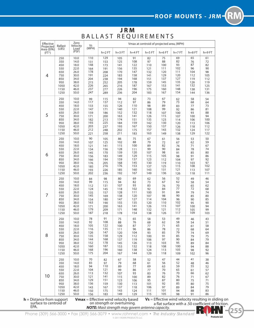
B A L L A S T R E Q U I R E M E N T SEffectiveProjectedArea (EPA)
(FT )2
Ballast(LBS)
ZeroVelocity
Load(PSF)
Vs(MPH)
Vmax at centroid of projected area, (MPH)
h=2 FT h=3 FT h=4 FT h=5 FT h=6 FT h=7 FT h=8 FT h=9 FT
250350450550650750850950
105011501250
250350450550650750850950
105011501250
250350450550650750850950
105011501250
250350450550650750850950
105011501250
250350450550650750850950
105011501250
250350450550650750850950
105011501250
10.014.018.022.026.030.034.038.042.046.050.0
10.014.018.022.026.030.034.038.042.046.050.0
10.014.018.022.026.030.034.038.042.046.050.0
10.014.018.022.026.030.034.038.042.046.050.0
10.014.018.022.026.030.034.038.042.046.050.0
10.014.018.022.026.030.034.038.042.046.050.0
110131148164178191204215226237247
99117133147159171182193203212221
90107121134145156166176185193202
8499
112124135145154163171179187
7892
105116126135144152160168175
708394
104113121129136143150156
129153173191208224238252265277289
115137155171186200213225237248258
105125141156170183194205216226236
98115131145157169180190200209218
91108122135147158168178187196204
8297
110121132141151159167175183
105125141156170183194205216226236
94112126140152163174184193202211
86102115128139149159168176185192
8094
107118128138147155163171178
7588
100111120129137145153160167
67798999
107115123130137143149
91108122135147158168178187196204
8297
110121132141151159167175183
7588
100111120129137145153160167
698293
102111120127135141148154
65768796
104112119126132138144
5868778693
100106113118124129
8297
110121132141151159167175183
738698
108118126135142150157163
67798999
107115123130137143149
62738392
100107114120126132138
5868778693
100106113118124129
52616977838995
101106111115
7588
100111120129137145153160167
67798999
107115123130137143149
6172829098
105112119125131136
566776849198
104110115121126
53627178859197
103108113118
475663707682879297
101105
698293
102111120127135141148154
62738392
100107114120126132138
566776849198
104110115121126
52627077849096
102107112117
4958657279859095
100105109
4452596570768085899498
65768796
104112119126132138144
5868778693
100106113118124129
53627178859197
103108113118
4958657279859095
100105109
46546168747984899498
102
4148556166717580848891
6172829098
105112119125131136
546473818894
100106112117122
5059677480869297
102107111
46546268748085909499
103
4351586469757984889296
3846525762677175798386
4
5
6
7
8
10
Vmax = Effective wind velocity based on strength or overturning.
h = Distance from support surface to centroid of EPA.
Vs = Effective wind velocity resulting in sliding on a flat surface with a .50 coefficient of friction.
NOTE: Mast strength may govern antenna capacity.

Phone (309) 566-3000 • Fax (309) 566-3079 • www.rohnnet.com • The Industry Standard
R O O F M O U N T S - J R M
256© 2011 ROHN PRODUCTS LLC
RMJ R M
B A L L A S T R E Q U I R E M E N T SEffectiveProjectedArea (EPA)
(FT )2
Ballast(LBS)
ZeroVelocity
Load(PSF)
Vs(MPH)
Vmax at centroid of projected area, (MPH)
h=2 FT h=3 FT h=4 FT h=5 FT h=6 FT h=7 FT h=8 FT h=9 FT
250350450550650750850950
105011501250
250350450550650750850950
105011501250
250350450550650750850950
105011501250
250350450550650750850950
105011501250
250350450550650750850950
105011501250
250350450550650750850950
105011501250
10.014.018.022.026.030.034.038.042.046.050.0
10.014.018.022.026.030.034.038.042.046.050.0
10.014.018.022.026.030.034.038.042.046.050.0
10.014.018.022.026.030.034.038.042.046.050.0
10.014.018.022.026.030.034.038.042.046.050.0
10.014.018.022.026.030.034.038.042.046.050.0
64758695
103110118124131137143
5970798895
102109115121127132
556574828996
102108113118124
52627077849096
102107112116
4958667380869196
101106110
475663707682879297
101105
7588
100111120129137145153160167
698293
102111120127135141148154
65768796
104112119126132138144
6172829098
105112119125131136
5868778693
100106113118124129
556574828995
102107113118123
6172829098
105112119125131136
566776849198
104110115121126
53627178859197
103108113118
5059677480869297
102107111
475663707682879297
101105
45536067727883889296
101
53627178859197
103108113118
4958657279859095
100105109
46546168747984899498
102
4351586469757984889296
4148556166717580848891
3946525863677276808387
475663707682879297
101105
4452596570768085899498
4148556166717580848891
3846525762677175798386
3743495459636771757882
3541475256606468717578
4351586469757984889296
4047535964697378828589
3744505560656973768083
3542475257616568727579
3339454954586165687175
3238434751555962656871
4047535964697378828589
3744495559646872767982
3541465156606467717477
3338444852566063677073
3137414650535760636669
2935394447515457606366
3744505560656973768083
3541465156606467717477
3238434852566063666972
3036414549535659626568
2934394347505356596265
2833374144485154565962
3542475257616568727579
3338444852566063677073
3036414549535659626568
2934384346505356596264
2732374044475053565861
2631353842454851535658
12
14
16
18
20
22
Vmax = Effective wind velocity based on strength or overturning.
h = Distance from support surface to centroid of EPA.
Vs = Effective wind velocity resulting in sliding on a flat surface with a .50 coefficient of friction.
NOTE: Mast strength may govern antenna capacity.

257Phone (309) 566-3000 • Fax (309)566-3079 • www.rohnnet.com • The Industry Standard© 2011 ROHN PRODUCTS LLC
ROOF MOUNTS - BRM4 RM
B R M 4N O N - P E N E T R A T I N G
Mount Part No.
BRM425
BRM430
BRM435
BRM440
BRM445
BRM455
BRM42510
BRM43510
BRM44510
Mast Part No.
KY1590
KY1592
KY1594
KY1596
KY1598
KY1600
KY2061
KY2063
KY2065
Mast Description & Height
2.38” O.D. x 0.154“ wall x 3.0’
2.88” O.D. x 0.203“ wall x 3.0‘
3.50” O.D. x 0.216“ wall x 3.0’
4.00” O.D. x 0.226“ wall x 3.0‘
4.50” O.D. x 0.237” wall x 3.0’
5.56“ O.D. x 0.258” wall x 3.0‘
2.38“ O.D. x 0.154” wall x 10.0’
3.50“ O.D. x 0.216” wall x 10.0‘
4.50” O.D. x 0.237” wall x 10.0’
MAST SPECIFICATIONS
6.5’Square
The BRM4 mount is hot-dip galvanized after fabrication for corrosion protection.
Order (1) optional BRM4MAT (1/8” thick) or (1) optional BRM4PAD (3/8” thick) for a protective barrier between the mount and the roof. Order (1) optional SCK150safety cable kit (3/16” x 150’).
Refer to pages 258-259 for ballast requirements. 2.38” to 5.56” Mast Tube Diameters
3’ and 10’ Overall Mast Heights(See Mast Descriptions)
16” Nominal Blocks

Phone (309) 566-3000 • Fax (309) 566-3079 • www.rohnnet.com • The Industry Standard
R O O F M O U N T S - B R M 4
258© 2011 ROHN PRODUCTS LLC
RMB R M 4
B A L L A S T R E Q U I R E M E N T SEffectiveProjectedArea (EPA)
(FT )2
Ballast(LBS)
ZeroVelocity
Load(PSF)
Vs(MPH)
Vmax at centroid of projected area, (MPH)
h=2 FT h=3 FT h=4 FT h=5 FT h=6 FT h=7 FT h=8 FT h=9 FT
300500700900
1100130015001700190021002300
300500700900
1100130015001700190021002300
300500700900
1100130015001700190021002300
300500700900
1100130015001700190021002300
300500700900
1100130015001700190021002300
300500700900
1100130015001700190021002300
7.111.816.621.326.030.835.540.245.049.754.4
7.111.816.621.326.030.835.540.245.049.754.4
7.111.816.621.326.030.835.540.245.049.754.4
7.111.816.621.326.030.835.540.245.049.754.4
7.111.816.621.326.030.835.540.245.049.754.4
7.111.816.621.326.030.835.540.245.049.754.4
171221261296328356383407431453474
121156185210232252271288305320335
99128151171189206221235249261274
86110131148164178191204215226237
7799
117133147159171182193203212
7090
107121134145156166176185193
242313370416448478506533558583604
171221262294317328358377395412427
140181214240259276292308322336349
121157185208224239253267279291302
108140166186201214226238250261270
99128151170183195207218228238247
198256302340366391414435456476493
140181214240259276292308322336349
114148175196211225239251263275285
99128151170183195207218228238247
89114135152164175185195204213220
81104123139149159169178186194201
171221262294317338358377395412427
121157185208224239253267279291302
99128151170183195207218228238247
86111131147159169179188197206213
7799
117132142151160169177184191
7090
107120129138146154161168174
153198234263284302320337353369382
108140166186201214226238250261270
89114135152164175185195204213220
7799
117132142151160169177184191
6989
105118127135143151158165171
638196
107116123131138144150156
140181214240259276292308322336349
99128151170183195207218228238247
81104123139149159169178186194201
7090
107120129138146154161168174
638196
107116123131138144150156
57748798
106113119126132137142
130167198223240256271285299312323
92118140157169181191201211220228
7597
114128138148156165172180186
658499
111120128135142149156161
587589
100107114121127134139144
5368819198
104111116122127132
121157185208224239253267279291302
86111131147159169179188197206213
7090
107120129138146154161168174
617893
104112120127133140146151
54708393
100107113119125130135
496476859298
103109114119123
114148175196211225239251263275285
81104123139149159169178186194201
6685
101113122130138145152159164
57748798
106113119126132137142
5166788895
101107112118123127
47607180869297
103107112116
2
4
6
8
10
12
Vmax = Effective wind velocity based on strength or overturning.
h = Distance from support surface to centroid of EPA.
Vs = Effective wind velocity resulting in sliding on a flat surface with a .50 coefficient of friction.
NOTE: Mast strength may govern antenna capacity.

259Phone (309) 566-3000 • Fax (309) 566-3079 • www.rohnnet.com • The Industry Standard© 2011 ROHN PRODUCTS LLC
ROOF MOUNTS - BRM4 RMB R M 4
B A L L A S T R E Q U I R E M E N T SEffectiveProjectedArea (EPA)
(FT )2
Ballast(LBS)
ZeroVelocity
Load(PSF)
Vs(MPH)
Vmax at centroid of projected area, (MPH)
h=2 FT h=3 FT h=4 FT h=5 FT h=6 FT h=7 FT h=8 FT h=9 FT
300500700900
1100130015001700190021002300
300500700900
1100130015001700190021002300
300500700900
1100130015001700190021002300
300500700900
1100130015001700190021002300
300500700900
1100130015001700190021002300
300500700900
1100130015001700190021002300
7.111.816.621.326.030.835.540.245.049.754.4
7.111.816.621.326.030.835.540.245.049.754.4
7.111.816.621.326.030.835.540.245.049.754.4
7.111.816.621.326.030.835.540.245.049.754.4
7.111.816.621.326.030.835.540.245.049.754.4
7.111.816.621.326.030.835.540.245.049.754.4
658499
112124135145154163171179
617892
105116126135144152160168
57748799
109119128136144151158
54708394
104113121129136143150
5267798999
107115123130137143
4964758695
103110118124131137
92118140157169181191201211220228
86111131147159169179188197206213
81104123139149159169178186194201
7799
117132142151160169177184191
7394
112126135144153161168176182
7090
107120129138146154161168174
7597
114128138148156165172180186
7090
107120129138146154161168174
6685
101113122130138145152159164
638196
107116123131138144150156
607791
102110118125131137143149
57748798
106113119126132137142
658499
111120128135142149156161
617893
104112120127133140146151
57748798
106113119126132137142
54708393
100107113119125130135
5267798996
102108114119124129
496476859298
103109114119123
587589
100107114121127134139144
54708393
100107113119125130135
5166788895
101107112118123127
486374839096
101107112117121
46607179869197
102106111115
4457687682879297
102106110
5368819198
104111116122127132
496476859298
103109114119123
47607180869297
103107112116
4457687682879297
102106110
425464727883889397
101105
40526269758084899397
101
496375849197
102108113118122
46597079859096
101106110114
4356667480859095
100104108
41536370768186909499
102
3950606772778286909497
3748576469747882869093
46597079859096
101106110114
435565747985909499
103107
40526269758084899397
101
3849596671768084889295
3747566368727680848891
3545536065697377818487
4356667480859095
100104108
40526269758084899397
101
3849586570758084889295
3647556267717579838790
3444535964687276798386
3343505761656973767982
14
16
18
20
22
24
Vmax = Effective wind velocity based on strength or overturning.
h = Distance from support surface to centroid of EPA.
Vs = Effective wind velocity resulting in sliding on a flat surface with a .50 coefficient of friction.
NOTE: Mast strength may govern antenna capacity.

Phone (309) 566-3000 • Fax (309) 566-3079 • www.rohnnet.com • The Industry Standard
R O O F M O U N T S - B R M 6
260© 2011 ROHN PRODUCTS LLC
RM
10’Square
B R M 6N O N - P E N E T R A T I N G
Mount Part No.
BRM630M
BRM635M
BRM640M
BRM645M
BRM655M
BRM665M
BRM64510M
Mast Description & Height
2.88” O.D. x 0.203“ wall x 4.0’
3.50” O.D. x 0.216“ wall x 4.0’
4.00” O.D. x 0.226“ wall x 4.0’
4.50” O.D. x 0.237“ wall x 4.0’
5.56” O.D. x 0.258” wall x 4.0’
6.63“ O.D. x 0.280” wall x 4.0’
4.50” O.D. x 0.237” wall x 10.0’
MAST SPECIFICATIONSMast Part No.
KY2110
KY1570
KY1578
KY1579
KY1580
KY1581
KY2043
The BRM6 mount is hot-dip galvanized after fabrication for corrosion protection.
Order (1) optional BRM6MAT (1/8” thick) or (1) optional BRM6PAD (3/8” thick)for a protective barrier between the mount and the roof. Order (1) optional SCK150 safety cable kit (3/16” x 150’).
Optional additional inner ballast support angle kit available, order P/N BRM6ABK.
Refer to pages 261-263 for ballast requirements.
2.88” to 6.63” Mast Tube Diameters
4’ and 10’ Overall Mast Heights(See Mast Descriptions)
16” Nominal Blocks

261Phone (309) 566-3000 • Fax (309) 566-3079 • www.rohnnet.com • The Industry Standard© 2011 ROHN PRODUCTS LLC
ROOF MOUNTS - BRM6 RM
B R M 64 F T . D I S H E L E V A T I O N
B A L L A S T R E Q U I R E M E N T S
DishDiameter
Ballast(LBS)
ZeroVelocity
Load(PSF)
Design Wind Velocities(MPH)
EL=0º EL=20º EL=40º
500750
10001250150017502000
500750
100012501500175020002250250027503000
750100012501500175020002250250027503000
4’(1.2 m)
6’(1.8 m)
8’(2.4 m)
Vmax Vs Vmax Vs Vmax Vs5.07.5
10.012.515.017.520.0
5.07.5
10.012.515.017.520.022.525.027.530.0
7.510.012.515.017.520.022.525.027.530.0
87107125139148157165
5871839399
105110115120125127
53626974788286909495
678295
106117126135
4555637178849095
100105110
41475358636771757982
103131154169180190196
658399
112120127130130130130130
57697985919798989898
7592
107119131141151
506171798794
101107113118123
46535965707580848892
112142167189203211211
6989
106120129137141141141141141
6073849096
102103103103103
92113131146160173185
61758797
107115123131138141141
56657380869298
103103103
Vmax = Effective wind velocity based on strength or overturning.
EL = Dish antenna azimuth angle with horizontal.
Vs = Effective wind velocity resulting in sliding on a flat surface with a .50 coefficient of friction.
NOTE: Mast strength may govern antenna capacity.

Phone (309) 566-3000 • Fax (309) 566-3079 • www.rohnnet.com • The Industry Standard
R O O F M O U N T S - B R M 6
262© 2011 ROHN PRODUCTS LLC
RMB R M 6
B A L L A S T R E Q U I R E M E N T SEffectiveProjectedArea (EPA)
(FT )2
Ballast(LBS)
ZeroVelocity
Load(PSF)
Vs(MPH)
Vmax at centroid of projected area, (MPH)
h=4 FT h=5 FT h=6 FT h=7 FT h=8 FT h=9 FT h=10 FT
500750
100012501500175020002250250027503000
500750
100012501500175020002250250027503000
500750
100012501500175020002250250027503000
500750
100012501500175020002250250027503000
500750
100012501500175020002250250027503000
500750
100012501500175020002250250027503000
5.07.5
10.012.515.017.520.022.525.027.530.0
5.07.5
10.012.515.017.520.022.525.027.530.0
5.07.5
10.012.515.017.520.022.525.027.530.0
5.07.5
10.012.515.017.520.022.525.027.530.0
5.07.5
10.012.515.017.520.022.525.027.530.0
5.07.5
10.012.515.017.520.022.525.027.530.0
99121140156171185198210221232242
8199
114128140151161171180189198
708699
110121131140148156164171
63778899
108117125133140147153
5770819099
107114121128134140
536575849199
106112118124129
128156180202218230242254265275280
104128147165178188198207216225228
90110128143154163171179187195198
8199
114128138146153160167174177
7490
104116126133140147153159161
688496
108116123130136141147149
114140161180195206217227237246250
93114132147159168177185193201204
8199
114128138146153160167174177
7288
102114123130137144150156158
668193
104113119125131137142144
61758696
104110116121127132134
104128147165178188198207216225228
85104120134145154162169176183186
7490
104116126133140147153159161
668193
104113119125131137142144
60748595
103109114120125130132
5668798895
101106111115120122
96118136152165174183192200208211
7996
111125134142150157163170173
688496
108116123130136141147149
61758696
104110116121127132134
5668798895
101106111115120122
52637382889398
103107111113
90110128143154163171179187195198
7490
104116126133140147153159161
647890
101109115121127132138140
5770819097
103108113118123125
52647482899499
104108112114
4859687682879296
100104106
85104120134145154162169176183186
698598
110119125132138144150152
60748595
103109114120125130132
546676859297
102107112116118
4960697884899398
102106108
45566472788286909498
100
8199
114128138146153160167174177
668193
104113119125131137142144
5770819097
103108113118123125
51637281879297
101106110112
475766748084899397
100102
4353616874788286899394
10
15
20
25
30
35
Vmax = Effective wind velocity based on strength or overturning.
EL = Dish antenna angle with horizontal.
Vs = Effective wind velocity resulting in sliding on a flat surface with a .50 coefficient of friction.
NOTE: Mast strength may govern antenna capacity.

263Phone (309) 566-3000 • Fax (309) 566-3079 • www.rohnnet.com • The Industry Standard© 2011 ROHN PRODUCTS LLC
ROOF MOUNTS - BRM6 RM
B R M 6B A L L A S T R E Q U I R E M E N T S
EffectiveProjectedArea (EPA)
(FT )2
Ballast(LBS)
ZeroVelocity
Load(PSF)
Vs(MPH)
Vmax at centroid of projected area, (MPH)
h=4 FT h=5 FT h=6 FT h=7 FT h=8 FT h=9 FT h=10 FT
500750
100012501500175020002250250027503000
500750
100012501500175020002250250027503000
500750
100012501500175020002250250027503000
5.07.5
10.012.515.017.520.022.525.027.530.0
5.07.5
10.012.515.017.520.022.525.027.530.0
5.07.5
10.012.515.017.520.022.525.027.530.0
49617078869299
105110116121
4757667481879399
104109114
445463707783889499
104108
647890
101109115121127132138140
60748595
103109114120125130132
5770819097
103108113118123125
5770819097
103108113118123125
546676859297
102107112116118
51637281879297
101106110112
52647482899499
104108112114
4960697884899398
102106108
475766748084899397
100102
4859687682879296
100104106
45566472788286909498
100
4353616874788286899394
4555647177818690949799
4352606773778185889293
4049576469737780848788
4352606773778185889293
4049576368727680838688
3847546065697276798283
4049576469737780848788
3847546065697276798283
3644515762656972757879
40
45
50
Vmax = Effective wind velocity based on strength or overturning.
EL = Dish antenna angle with horizontal.
Vs = Effective wind velocity resulting in sliding on a flat surface with a .50 coefficient of friction.
NOTE: Mast strength may govern antenna capacity.

Phone (309) 566-3000 • Fax (309) 566-3079 • www.rohnnet.com • The Industry Standard
R O O F M O U N T S - N P P K
264© 2011 ROHN PRODUCTS LLC
RM
N P P KN O N - P E N E T R A T I N G
3.4’
Mount Adjusts to Roof Angle
The NPPK mount is a great solution for broadband antennas and satellite TV dishes. The adjustable mounting plate can be center mounted or to one side as needed to accommodate other satellite TV dish mounts. Our 1LG mount (located on page 274) with a base and 1-1/4” mounting tube can be attached to the NPPK. The mount comes standard with double ballast trays on each side tohold concrete blocks. The NPPK mount is hot-dip galvanized after fabrication for corrosion protection.
Order (2) optional FRMMAT (1/8” thick) or (2) optional FRMPAD (3/8” thick) for a protective barrier between the mount and the roof. Order (1) optional SCK150 safety cable kit (3/16” x 150’).
3’
AdjustableMounting Plate
16” NominalBlocks

265Phone (309) 566-3000 • Fax (309) 566-3079 • www.rohnnet.com • The Industry Standard© 2011 ROHN PRODUCTS LLC
ROOF MOUNTS - 25GBRM RM
2 5 G B R MN O N - P E N E T R A T I N G
The 25GBRM mount is designed to support one or two 25G tower sections in a self-supporting application. The 25GBRM mount is galvanized after fabrication for corrosion protection.
Order (1) optional BRM6MAT (1/8” thick) or (1) optional BRM6PAD (3/8” thick) for a protective barrier between the mount and the roof. Order (1) optional SCK150 safety cable kit (3/16” x 150’).
Refer to page 266 for ballast requirements.
Standard 25G sections mountto top of 25GBRM
10’ Square
Overall Mast Heights(1) 25G Section - 12.4’(2) 25G Sections - 22.4’
16” Nominal Blocks
Phone (309) 566-3000 • Fax (309) 566-3079 • www.rohnnet.com • The Industry Standard
R O O F M O U N T S - 2 5 G B R M
266© 2011 ROHN PRODUCTS LLC
RM
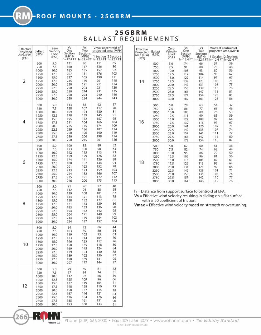
2 5 G B R MB A L L A S T R E Q U I R E M E N T S
EffectiveProjectedArea (EPA)
(FT )2
Ballast(LBS)
ZeroVelocity
Load(PSF)
VsOne
Section(MPH)
h=12.4 FT
Vmax at centroid of projected area, (MPH)
VsTwo
Sections(MPH)
h=22.4 FT1 Sectionh=12.4 FT
2 Sectionsh=22.4 FT
500750
100012501500175020002250250027503000
500750
100012501500175020002250250027503000
500750
100012501500175020002250250027503000
500750
100012501500175020002250250027503000
500750
100012501500175020002250250027503000
500750
100012501500175020002250250027503000
5.07.5
10.012.515.017.520.022.525.027.530.0
5.07.5
10.012.515.017.520.022.525.027.530.0
5.07.5
10.012.515.017.520.022.525.027.530.0
5.07.5
10.012.515.017.520.022.525.027.530.0
5.07.5
10.012.515.017.520.022.525.027.530.0
5.07.5
10.012.515.017.520.022.525.027.530.0
131160185207227245250250250250250
113138159178195211225239250250250
100123142159174188201213224235246
91112129144158171183194204214224
84103119133146158169179189198207
7997
112125137148158167176185193
96117135151165179191203214224234
88107124139152164175186196206215
82100115129141152163173182191200
7694
108121132143153162171179187
7289
102114125135145153162169177
698497
109119128137146154161168
111136157176190201211221231240244
92112130145157166174182190198201
8098
113126136144152159166172175
7288
101113122129136142149154157
668093
104112118124130136141144
61748696
104110115121126131133
658092
103111118124130135140143
5770819198
104109114119124126
52637382889498
103107112113
485867758186909599
103104
4454637076808488929597
4251596671757983869091
2
4
6
8
10
12
EffectiveProjectedArea (EPA)
(FT )2
Ballast(LBS)
ZeroVelocity
Load(PSF)
VsOne
Section(MPH)
h=12.4 FT
Vmax at centroid of projected area, (MPH)
VsTwo
Sections(MPH)
h=22.4 FT1 Sectionh=12.4 FT
2 Sectionsh=22.4 FT
500750
100012501500175020002250250027503000
500750
100012501500175020002250250027503000
500750
100012501500175020002250250027503000
5.07.5
10.012.515.017.520.022.525.027.530.0
5.07.5
10.012.515.017.520.022.525.027.530.0
5.07.5
10.012.515.017.520.022.525.027.530.0
7491
105117129139149158166174182
7086
100111122132141149157165172
678295
106116126134142150157164
668093
104114123131139147154161
63778999
109118126133141147154
60748696
105113121128135142148
5770809097
103108113118123125
546676859297
102107111116118
51627281879297
101106110112
3948566267717578818586
3746535964677174778082
3644505661646871747778
14
16
18
h = Distance from support surface to centroid of EPA.Vs = Effective wind velocity resulting in sliding on a flat surface with a .50 coefficient of friction.Vmax = Effective wind velocity based on strength or overturning.

267Phone (309) 566-3000 • Fax (309) 566-3079 • www.rohnnet.com • The Industry Standard© 2011 ROHN PRODUCTS LLC
ROOF MOUNTS - AAGM RM
A A G MN O N - P E N E T R A T I N G
Mount Part No.
AAGM35
AAGM40
AAGM45
AAGM55
AAGM6560
Mast Part No.
FYS75
FYS76
FYS77
FYS78
FYS96
Mast Description & Height
3.50” O.D. x 0.216” wall x 4.5’
4.00” O.D. x 0.226” wall x 4.5’
4.50” O.D. x 0.237 wall x 4.5’
5.56” O.D. x 0.258” wall x 4.5’
6.63” O.D. x 0.280” wall x 5.0’
MAST SPECIFICATIONS
16.3’
14.3’
The AAGM mount is capable of supporting dishes with diameters up to 10 feet. The AAGM mount is hot-dip galvanized after fabrication for corrosion protection.
Order (1) optional AGMMAT (1/8” thick) or (1) optional AGMPAD (3/8” thick) for a protective barrier between the mount and the roof. Order (1) optional SCK150 safety cable kit (3/16” x 150’).
Refer to page 268 for ballast requirements.
3.50” to 6.63” Mast Tube Diameters2.5’ and 5’ Overall Mast Heights(See Mast Descriptions)
16” Nominal Blocks

Phone (309) 566-3000 • Fax (309) 566-3079 • www.rohnnet.com • The Industry Standard
R O O F M O U N T S - A A G M
268© 2011 ROHN PRODUCTS LLC
RM
A A G M4 . 5 F T D I S H E L E V A T I O N
B A L L A S T R E Q U I R E M E N T S
DishDiameter
Ballast(LBS)
ZeroVelocity
Load(PSF)
Vmax(MPH)
Vs (MPH)
EL=0º EL=20º EL=40º
100015002000250030003500400050006000
100015002000250030003500400050006000
100015002000250030003500400050006000
100015002000250030003500400050006000
4’(1.2 m)
6’(1.8 m)
8’(2.4 m)
10’(3.0 m)
6.09.0
12.015.118.121.124.130.136.1
6.09.0
12.015.118.121.124.130.136.1
6.09.0
12.015.118.121.124.130.136.1
6.09.0
12.015.118.121.124.130.136.1
135164187207225240250250250
90109125138150160165165165
688294
104112120125125125
465664717782858585
91111128143157170181203222
60748596
105113121135148
45566472798591
101111
313844495458626976
93114132147161174186208228
62768898
108116124139152
47576674818793
104114
334046525761657380
101123142159174188201225246
678295
106116125134150164
506271798794
101112123
404957647075808585
Vmax = Effective wind velocity based on strength or overturning.
EL = Dish antenna azimuth angle with horizontal.
Vs = Effective wind velocity resulting in sliding on a flat surface with a .50 coefficient of friction.
NOTE: Mast strength may govern antenna capacity.

269Phone (309) 566-3000 • Fax (309) 566-3079 • www.rohnnet.com • The Industry Standard© 2011 ROHN PRODUCTS LLC
ROOF MOUNTS - PRM6 RM
P R M 6N O N - P E N E T R A T I N G
Mount Part No.
PRM635
PRM640
PRM645
PRM655
Mast Description
3.50” O.D. x 0.216“ wall
4.00” O.D. x 0.226“ wall
4.50” O.D. x 0.237“ wall
5.50” O.D. x 0.258” wall
MAST SPECIFICATIONSMast Part No.
KY1672
KY1673
KY1674
KY1675
2.4’
10.4 ’
DishDiameter
Ballast(LBS)
ZeroVelocity
Load(PSF)
Design Wind Velocities(MPH)
EL=0º EL=20º EL=40º
16001800200022002400
160018002000220024002600280030003200340036003800
4’(1.2 m)
6’(1.8 m)
Vmax Vs Vmax Vs Vmax Vs17.219.421.523.725.8
17.219.421.523.725.828.030.132.334.436.638.740.9
145154162168171
97102108112114116118120122124125125
122130137144150
81869196
100104108112115119122125
180184187189189
117123125126126126126126126126126126
137146154161168
9197
102107112117121125126126126126
198198198198198
126132132132132132132132132132132132
168179188197198
112119125131132132132132132132132132
BALLAST REQUIREMENTS
The PRM6 mount is capable of supporting dishes with diameters up to 6 feet. The mount is hot-dip galvanized after fabrication forcorrosion protection. Th PRM6 mount is also UPS shippable.
Order (1) optional PRM6MAT (1/8” thick) or (1) optional PRM6PAD (3/8” thick) for a protective barrier between the mount and the roof. Order (1) optional SCK150 safety cable kit (3/16” x 150’).
Vmax = Effective wind velocity based on strength or overturning.
EL = Dish antenna azimuth angle with horizontal.
Vs = Effective wind velocity resulting in sliding on a flat surface with a .50 coefficient of friction.
NOTE: Mast strength may govern antenna capacity.
Concrete blocks notprovided with mount.
Post Tensioning Rods (TYP)
3.50” to 5.50” Mast Tube Diameters 5.0’ Overall Mast Heights(See Mast Descriptions)

Phone (309) 566-3000 • Fax (309) 566-3079 • www.rohnnet.com • The Industry Standard
R O O F M O U N T S
270© 2011 ROHN PRODUCTS LLC
RM
B A L L A S T R E Q U I R E M E N T S F O R R O O F M O U N T S 1. Ballast requirements are provided to assist consumers in determining the applicability of a non-penetrating roof mount for an antenna installation and to assist in determining the amount of ballast required. The ballast requirements should not be relied upon without competent local professional examination and verification of its accuracy and suitability for a specific site or application. 2. Specific antennas and/or other mounting configurations may require more stringent strength and ballast requirements and must be investigated for each installation. The load carrying requirements of the supporting surface, the mount and mast, the antenna and the antenna’s connection to the mast must be investigated for each installation. 3. When antenna areas are indicated vs. specific antenna types, the areas tabulated are effective projected areas that include appropriate wind drag factors applied to the projected areas of the supported antennas and the exposed portions of the mount and ballast. The center of the effective projected area is assumed to be at the top of the mounting pipe or the height indicated in the ballast table. Unless otherwise indicated, tabulated ballast requirements assume that the effective projected areas are concentric to the mount and that uplift or download wind forces are insignificant. 4. The tabulated wind velocities are considered to occur at the centroid of the effective projected areas. The wind velocity appropriate for an installation must be determined on an individual site basis considering the location and elevation of the mount. The wind velocity at ground level must be multiplied by appropriate height escalation and gust factors. Potential increases in wind velocity due to channeling, roof projections, and other obstructions, must also be considered when determining ballast requirements. 5. The ballast weights indicated are assumed to be uniformly distributed on the mount. The weight of the mount and antenna may be considered as ballast. Mounts are assumed to be mounted on a flat supporting surface. 6. The zero velocity loads shown are equal to the tabulated ballast weights divided by the total area enclosed by the perimeter of the mount. This area is greater than the ballast contact area. Loads which must be investigated include reactions caused by wind forces and moments, live loads, ice loads, earthquake loads and the dead loads of ballast, mount, antenna, mounting hardware, miscellaneous equipment and roof pads. 7. The tabulated maximum wind velocities (Vmax) are based on a minimum 1.5 factor of safety against structural failure and overturning. 8. The tabulated wind velocities resulting in sliding (Vs) are based on a factor of safety equal to 1.0 and an effective coefficient of friction equal to 0.50 between the mount and a flat supporting surface. A 1.0 factor of safety was used assuming that at higher wind velocities, safety cables or other suitable attachments to the support structure would prevent sliding beyond a safe, designated area. 9. The appropriate coefficient of friction and factor of safety to determine wind velocities resulting in sliding must be determined on an individual site basis. The coefficient of friction may vary under changing moisture and temperature conditions. The minimum coefficient of friction must be used to evaluate sliding resistance. Wind speeds resulting in sliding for other factors of safety or for other coefficients of friction may be found by multiplying the tabulated values of Vs by the following modification factor: Modification Factor = [µ /(.5 x FS)]1/2
µ= Coefficient of Friction FS = Factor of Safety10. The values of Vs indicated do not apply for installations which are prevented from sliding by cables or other suitable attachments to the supporting structure.
11. Roof pads are recommended to prevent damage to roof membranes. Pads should be placed under all contact areas.
12. ROHN recommends that ballast material always be placed prior to mounting the antenna and that roof pads and mount be secured to prevent hazards from occurring under extreme wind loading conditions. Precautions should also be taken to prevent the inadvertent removal of ballast material after installation and to insure that all ballast material is fully supported by the mount (required for ballast to be effective in resisting overturning and sliding).
13. When adhesives are used to secure roof pads, the adhesive must be compatible with the supporting surface. Precautions should be taken to insure that damage to the supporting surface will not occur upon wind loading.
14. The installation, roof material and supporting structure must be capable of withstanding all loads imposed by the antenna system. Supporting surfaces, anchors and/or safety cables must be sufficient to resist the reactions from the antenna system. The installation must meet all applicable local, state and federal requirements.

271Phone (309) 566-3000 • Fax (309) 566-3079 • www.rohnnet.com • The Industry Standard© 2011 ROHN PRODUCTS LLC
ROOF MOUNTS - URM RM
U R M
Features: 1. URM mount can be used on a flat roof, sloped roof or over a roof peak. 2. URM mount can be used with 2.88” to 4.50” O.D. masts (order separately). 3. Bottom of mount pivots to match roof pitch. 4. Rear leg adjusts for extra length. 5. Mount base angles are pre-drilled to accept 1/2” diameter connectors.
Optional Masts - Ordered Separately
P2530 2.88” O.D. x 0.203“ wall x 30” LongP330 3.50” O.D. x 0.216“ wall x 30” LongP3530 4.00” O.D. x 0.226“ wall x 30” LongP430 4.50” O.D. x 0.237“ wall x 30” Long
16”24” 28”
25”
ROHN’s Universal Roof Mount (URM) is capable of supporting most PCS, Cellular, and Microwave antennas. The URM adapts to various roof pitches and the fully adjustable rear-leg allows for use on a �at or up to a 12”/12” pitched roof. Installation is easy because of the quick adaptability, plus there’s no need for concrete blocks. The URM is hot-dip galvanized after fabrication for corrosion protection, and can easily ship UPS.
Braces provided with multiple holes to allow+ / - 26” of lengthadjustment.

Phone (309) 566-3000 • Fax (309) 566-3079 • www.rohnnet.com • The Industry Standard
R O O F M O U N T S - S H R M
272© 2011 ROHN PRODUCTS LLC
RM
S H R M
26”28”
24”
16”
Features: 1. SHRM mount can be used on a flat roof or on a roof peak, up to 45 degrees maximum pitch. 2. SHRM mount can be used with 2.88” to 5.00” O.D. masts (ordered separately). 3. Bottom of mount pivots to match roof pitch. 4. Mount base angles are pre-drilled to accept 1/2” diameter connectors.
ROHN’s Saw Horse Roof Mount (SHRM) is capable of supporting most PCS, Cellular, and Microwave antennas. The SHRM allows for placement of antennas on �at roofs or roof peaks with up to a 12”/12” pitch. The SHRM is also able to be installed on �at roofs. Installation is easy because of the quick adaptability, plus there’s no need for concrete blocks. The SHRM is hot-dip galvanized after fabrication for corrosion protection, and can easily ship UPS.
Optional Masts - Ordered Separately
P2530 2.88” O.D. x 0.203“ wall x 30” LongP330 3.50” O.D. x 0.216“ wall x 30” LongP3530 4.00” O.D. x 0.226“ wall x 30” LongP430 4.50” O.D. x 0.237“ wall x 30” Long
28”

273Phone (309) 566-3000 • Fax (309) 566-3079 • www.rohnnet.com • The Industry Standard© 2011 ROHN PRODUCTS LLC
ROOF MOUNTS - TRT RM
T R T 3 6 / T R T 6 0 / T R T A G 2
Description
3’ tall, tube legs (PG)
5’ tall, tube legs (PG)
5’ tall, angle legs (HDG)with 2.38” O.D. x 0.154“ wall x 3.5’ long mast (HDG)
SPECIFICATIONSPart No.
TRT36
TRT60
TRTAG2
TRT60
The TRT is a Tripod Roof Tower, which comes fully assembled and snaps out into position for quick installation using up to 1/4” dia. connectors. The TRTAG2 mount comes with a 2 3/8” O.D. hot-dip galvanized mast, the TRT36 and TRT60 mounts accept masts up to 1 3/4” O.D. (ordered separately). The bolt-on swivel feet adjust to most any pitch roof. TRT mounts are galvanized for corrosion protection. All TRT mounts are UPS shippable.
TRTAG2
TRT36
Angle leg
Tube leg
TRTAG2 comes with a 2 3/8” O.D. mast.Masts must be ordered separately for
the TRT36 and TRT60.
Please see page 301 for mast options.
TRT36 and TRT60 �t ROHN’s Telescoping masts
(see pages 244-249).
PG = Pre-galvanizedHDG = Hot-dip galvanized
Mast