effectiveness of rectangular spiral shear reinforcement on infilled r/c frames...
TRANSCRIPT

This article was downloaded by: [TEI of Serres ]On: 17 November 2011, At: 22:20Publisher: Taylor & FrancisInforma Ltd Registered in England and Wales Registered Number: 1072954 Registeredoffice: Mortimer House, 37-41 Mortimer Street, London W1T 3JH, UK
Journal of Earthquake EngineeringPublication details, including instructions for authors andsubscription information:http://www.tandfonline.com/loi/ueqe20
Effectiveness of Rectangular Spiral ShearReinforcement on Infilled R/C FramesUnder Cyclic LoadingD. J. Kakaletsis a , C. G. Karayannis b & G. K. Panagopoulos aa Department of Civil Engineering, Technological EducationalInstitution of Serres, Serres, Greeceb Department of Civil Engineering, Democritus Univercity of Thrace,Xanthi, Greece
Available online: 09 Nov 2011
To cite this article: D. J. Kakaletsis, C. G. Karayannis & G. K. Panagopoulos (2011): Effectivenessof Rectangular Spiral Shear Reinforcement on Infilled R/C Frames Under Cyclic Loading, Journal ofEarthquake Engineering, 15:8, 1178-1193
To link to this article: http://dx.doi.org/10.1080/13632469.2011.560361
PLEASE SCROLL DOWN FOR ARTICLE
Full terms and conditions of use: http://www.tandfonline.com/page/terms-and-conditions
This article may be used for research, teaching, and private study purposes. Anysubstantial or systematic reproduction, redistribution, reselling, loan, sub-licensing,systematic supply, or distribution in any form to anyone is expressly forbidden.
The publisher does not give any warranty express or implied or make any representationthat the contents will be complete or accurate or up to date. The accuracy of anyinstructions, formulae, and drug doses should be independently verified with primarysources. The publisher shall not be liable for any loss, actions, claims, proceedings,demand, or costs or damages whatsoever or howsoever caused arising directly orindirectly in connection with or arising out of the use of this material.

Journal of Earthquake Engineering, 15:1178–1193, 2011Copyright © A. S. Elnashai & N. N. AmbraseysISSN: 1363-2469 print / 1559-808X onlineDOI: 10.1080/13632469.2011.560361
Effectiveness of Rectangular Spiral ShearReinforcement on Infilled R/C Frames Under
Cyclic Loading
D. J. KAKALETSIS1, C. G. KARAYANNIS2,and G. K. PANAGOPOULOS1
1Department of Civil Engineering, Technological Educational Institution ofSerres, Serres, Greece2Department of Civil Engineering, Democritus Univercity of Thrace, Xanthi,Greece
The effect of two types of shear reinforcement, with reference to two types of masonry infills, onthe seismic performance of reinforced concrete (RC) frames was experimentally investigated. Sixsingle-story, one-bay, 1/3-scale frame specimens were tested under cyclic horizontal loading, up toa drift level of 40‰. Bare frames and infilled frames with two different infill compressive strengthswere sorted into two groups based on stirrups or spirals as shear reinforcement. From the observedresponses it can be deduced that rectangular spiral reinforcement is a first experience and moreexperiments are needed.
Keywords Infilled R/C Frames; Experiments; Shear Reinforcement; Rectangular Spirals; MasonryStrength
1. Introduction
In concrete buildings, in addition to the vertical elements (walls and columns) and thebeams framing into them, which form the system charged with the task of resisting theseismic action, some elements may have secondary role in, and contribution to earthquakeresistance — or considered so by the designer, for convenience. Among them, non struc-tural elements, notably masonry infills, may interfere in the seismic response with meansother than their mass. Field experience and analytical and experimental research [Fardis andPanagiotakos, 1997; Fardis, 2000] demonstrated their overall beneficial effect on seismicperformance, especially when the building structure itself has poor engineered earthquakeresistance. However, if the contribution of masonry infills to the lateral strength and stiff-ness of the building is large relative to the strength and stiffness of the structure itself, theinfills may override the seismic design of the structure and undermine the efforts of thedesigner and the intention of design codes to control the inelastic response by spreadingthe inelastic deformation demands throughout the structure [Fardis, 2009].
In addition to this potential detrimental effect of infills on global response, there mayalso be local adverse effects of infills [Moghadam and Dowling, 1987; CEB, 1996; FEMA
Received 13 July 2010; accepted 28 January 2011.Address correspondence to D. J. Kakaletsis, Technological Educational Institution of Serres, Serres 62124,
Greece; E-mail: [email protected]
1178
Dow
nloa
ded
by [
TE
I of
Ser
res
] at
22:
20 1
7 N
ovem
ber
2011

Effectiveness of Rectangular Spiral Reinforcement 1179
356, 2000]. Among these, there is the case of stiff and strong infills that may shear–offweak columns, especially for imbalanced (i.e., one–sided) contact. According to the aboveadverse local effect, failure or heavy damage of an infill panel may dislodge part of it,exerting a concentrated force on the adjacent column. The stronger the infill, the larger is themagnitude of this force and the higher the likelihood of column shear failure. Infill panelsare more likely to fail or suffer heavy damage, from plane mechanisms, at the ground storey,as there the shear force demand is largest, although it has been observed in earthquakesthat panels at higher stories might collapse due to combined in-plane and out-of-planeaction and that out-of-plane action typically increases with the height. Column failure dueto imbalanced contact with infills may take place in columns which are exterior in the planeof the frame.
Eurocode 8 [CEN, 2004], has rules to protect concrete buildings from this type ofadverse local effects. They apply to buildings designed for DC H or M (not for L), no matterthe structural system (wall or frame). According to these rules, if there is no architecturalor conceptual design solution for the captive columns, we are left with dimensioning anddetailing them for the adverse effect of the infill as follows:
To prevent failure, the length of the column against which the diagonal strut bearsshould be verified in shear for the smallest of the following design shear forces, as shownin Fig. 1:
a. the horizontal component of the strut force of the infill, taken equal to the horizontalshear strength of the panel estimated from the shear resistance of bed joints (shearstrength of bed joints times the wall thickness, tw, times the clear length of the infillpanel L) ; or
b. the capacity design shear force, VCD,c, taken equal to twice the design value of thecolumn flexural capacity, 2M Rc, times the factor γ RD, divided by the clear lengthof the column, H, taking as equal to the contact length, lc.
In case (b), the contact length should be taken equal to the full vertical width of the diagonalstrut of the infill, winf / cosθ , where winf is the strut width in the plane of the infill and θ isthe angle between the horizontal and the panel diagonal: θ = arctan (H / L). This contact
FIGURE 1 Shear loading of column by the strut force of the infill.
Dow
nloa
ded
by [
TE
I of
Ser
res
] at
22:
20 1
7 N
ovem
ber
2011

1180 D. J. Kakaletsis et al.
length is consistent with the calculation in case (a), which conservatively assumes that thefull strut force is applied to the column. It is also closer to reality at the column, as therethe joint between the top of the infill and the soffit of the beam may already be open due toshrinkage of masonry, construction details or inadequate mortar filling.
Behind this calculation, in buildings with masonry infills, Eurocode 8 [CEN, 2004]imposes the special detailing and confinement requirements for column critical regionsover the full clear height of the columns of the ground story, to help them withstand localoverloading due to dislodgement of the infill at any point along their height. Eurocode 8[CEN, 2004] subjects also the entire length of columns that are in contact with infills on oneside only per vertical plane to the special detailing and confinement requirements applyingto critical regions. This transverse reinforcement increases the nominal shear resistanceof the captive column over its full height beyond the design shear force for which it hasbeen verified and enhances its deformation capacity for any potential location of the plastichinges.
However, if the clear length of the column, H, (i.e., the contact length, lc) is short, thedesign shear force may come out so large that it may not be feasible to verify the column forit, especially if shear resistance is governed by shear compression and cannot be increasedfurther through transverse reinforcement.
Another option is to place continuous rectangular spiral shear reinforcement alongRC frame members. Such alternative reinforcement, replacing the conventional trans-verse reinforcement of the column, is expected to be effective for energy dissipationand deformation capacity and they may be dimensioned to resist at the same time thedesign shear force. Considering that the application of the rectangular spiral reinforcement(RSR) can contribute to the improvement of the external beam-column joint properties,as it, already, has been presented in Karayannis et al. [2005] and Kakaletsis [2007], it isexpected to contribute to the total improvement of the response of infilled frames, if someadverse aspects that have been noted in the past for circular spirals — which, at least insome countries, have been prohibited — could be experimentally clarified for rectangularspirals too.
On the other hand, it is generally accepted that the use of continuous spiral reinforce-ment in concrete elements with cyclic cross section can substantial improve the strengthand the ductility of the concrete and henceforth the total seismic response and capacity ofthe structural element [Park and Paulay, 1975]. International codes in these cases proposeincreased performance factors for the concrete confinement (ACI 318, EC8). The extensionof the use of continuous spiral reinforcement in elements with rectangular cross sectionscould be an alternative specific technical choice for stirrups, taking into account that nowa-days the possible industrialization of reinforcing steel is essential to maintain the R/Cstructures sustainable for economic issues.
In this article the experimental results that are presented are a part from an experi-mental program that has the aim to investigate the performance of masonry–infilled RCframes under in-plane lateral cyclic loads [Kakaletsis and Karayannis, 2008; Kakaletsis,2009]. The purpose of the present article is primarily: (a) finding the effect of two typesof shear reinforcement that is spirals and equally spaced stirrups, on the lateral strength,stiffness, and energy dissipation capacity of infilled frames; (b) examining the shear rein-forcement efficiency with reference to two types of masonry infills that had differentcompressive strength but almost identical shear strength, under identical geometry andloading conditions. Both qualitative and quantitative conclusions, based on the observedmaximum loads, loading stiffness and hysteretic energy absorption are presented andcompared.
Dow
nloa
ded
by [
TE
I of
Ser
res
] at
22:
20 1
7 N
ovem
ber
2011

Effectiveness of Rectangular Spiral Reinforcement 1181
2. Experimental Program
2.1. Test Specimens
The experimental program, as shown in Table 1, consisted of testing six single-story, one-bay, 1/3-scale specimens of reinforced concrete bare frames and frames with infills ofclay brick and vitrified ceramic brick. The program results provide data for the evalua-tion of the influence of different transverse reinforcement and different infill compressivestrengths on the surrounding frames. Specimens of group A had transverse steel in theform of common stirrups while specimens of group B had continuous rectangular spi-ral reinforcement of the same spacing respectively. The geometric characteristics of theRC frames were the same for all specimens. The elevation, the corresponding cross-sections of the members, and the design details for the RC frame specimens are shownin Figs. 2a,b. The beam and the column cross sections were 100×200 mm and 150×150mm respectively. The above dimensions corresponds to 1/3 scale of the prototype framesections, 300×600 mm for the beam and 450×450 mm for the column. The two rein-forcement arrangements considered in tests are presented in Fig. 3. The column hadcloser ties throughout the length, because the entire length of columns that are in con-tact with infills on one side per vertical plane are subjected to the special detailing andconfinement requirements applying to critical regions. The beam had more shear rein-forcement in the critical regions. Each beam-to-column joint had five horizontal stirrupsto prohibit brittle shear failure. The longitudinal reinforcement diameter �5.60 mm andstirrups diameter �3 mm of the frame members corresponds to 1/3 scale of �18 mmand �8 mm reinforcement diameters, respectively, of the prototype frame. The trans-verse reinforcement in the critical regions of specimens satisfied the requirements of theGreek standards, sh = 34 mm ≈ sh(required) = 33.3 mm for the columns and sh = 40 mm <
sh(required) = 56 mm for the beams and corresponds to 1/3 scale of sh = 100 mm ≈ sh(required)
for the columns and sh = 120 mm < sh(required) = 180 cm for the beams of the prototypeframe. At the specimens, low strength plain bars were used, although the rule for the con-struction practice is to use high strength deformed bars. The reinforced concrete frame
TABLE 1 Test specimens
Masonry type Shear reinforcement type
Group SpecimenBareframe Weak Strong
Commonstirrups
Rectangularspirals
A B � �
S � �
IS � �
B BS � �
SS � �
ISS � �
Dow
nloa
ded
by [
TE
I of
Ser
res
] at
22:
20 1
7 N
ovem
ber
2011

1182 D. J. Kakaletsis et al.
(a)
(b) (c)
FIGURE 2 Description of infilled frame specimens: (a) reinforcement detailing of the RCframe models (mm); (b) infilled frame and instrumentation (cm); (c) weak and strong brickunits (mm).
(a) (b)
FIGURE 3 Reinforcement arrangements considered in tests: (a) Specimens of group Awith stirrups; (b) specimens of group B with spirals (color figure available online).
represented a typical ductile concrete construction, built in accordance with the currentlyused codes and standards in Greece, which are very similar to EC2 and EC8. The aver-age sum of the flexural capacity of column to that of beam was also confirmed by thesestandards. Thus, for the beam-column connections examined in this investigation, the ratio
Dow
nloa
ded
by [
TE
I of
Ser
res
] at
22:
20 1
7 N
ovem
ber
2011

Effectiveness of Rectangular Spiral Reinforcement 1183
was 1.50, greater than 1.40. The purpose was to push the formation of plastic hinge in thebeams. Masonry infill in the model had a height of 800 mm and a length of 1,200 mm, asshown in Fig. 2b, representing an exterior partition wall of the prototype structure with aheight of 2.40 m and a length of 3.60 m (height against length ratio H/L=1/1.50). In theexperiments, a brick with dimensions 60×60×93 mm was used for the “weak” commonclay brick usually used in Greece and obtained by cutting a certain brick with dimensions60×90×185 mm. The experimental brick unit corresponds to 1/3 scale of the prototypebrick unit with dimensions 180×180×300 mm, which is used in typical partition walls.On the other hand, a brick with dimensions 52×45×95 mm was used for the “strong” vit-rified ceramic brick that proved to be important for the specimen behaviour and obtainedby cutting an available on the market brick with dimensions 52×45×190 mm. The exper-imental brick unit corresponds to 1/3 scale of the prototype brick unit with dimensions160×140×300 mm. It is obvious that the partition wall was not scaled down very success-fully in this case. Brick shape is shown in Fig. 2c. A representative mortar mix was usedfor the two types of infills contained the portions 1:1:6 (cement: lime: sand) and producedmechanical properties similarly to type M1 mortar according to EN 998-2 standard [CEN,2001]. Infills were designed so that the lateral cracking load of the infill is less than theavailable column shear resistance. Masonry properties, as presented in Sec. 2.2, were cho-sen in such a way to obtain the desired weak masonry lateral strength for both infill types.Cracking shear of infill without the confinement offered by the surrounding frame was:
Vw,u = fv · t · L = 27.36 or 25.58 kN, (1)
where fv is the masonry shear strength of the bed joints subjected to normal stress fn, fromdiagonal tests on full size bare infills (fv/fn = L/H= 1.5/1, as shown in Table 2), L is thelength of masonry infill, t is the thickness of masonry infill. It must be pointed out thatshear strength of the weak masonry wall is a little higher than the corresponding one of thestrong masonry, due to the thickness reduction. Assuming that plastic hinges occurred atthe bottom and the top of the columns, flexural resistance of the bare frame was:
Ff = Mpc/h = 42.48 kN, (2)
where 4Mpc is the plastic moment of the column considering the effect of the axial force,h = H-lp, H is the height of masonry infill, lp is the plastic hinge length equal to 0.5 timesthe column depth. Vw,u was lower than Ff. This closely represents actual construction inGreece.
2.2. Material Properties
Material tests were conducted on concrete, reinforcing steel and masonry samples as havebeen presented in Kakaletsis and Karayannis, [2008]. The mean compressive strength ofthe frame concrete was 28.51 MPa. The yield stress of longitudinal and transverse steel was390.47 and 212.2 MPa, respectively. The main results of mortar, bricks, and infill masonrytests are presented in Table 2. The relationship of the shear strength of the bed joints fv
vs. the normal stress fn, derived from the cohesion tests and the diagonal compression testsof masonry panels with various length L to height H ratios and full size panels as well(fv/fn = L/H) is presented in Table 2. It can be noted from Table 2 that the compressivestrength of the “weak” masonry prisms was lower than that of the “strong” ones while the
Dow
nloa
ded
by [
TE
I of
Ser
res
] at
22:
20 1
7 N
ovem
ber
2011

1184 D. J. Kakaletsis et al.
TABLE 2 Mechanical properties of the materials used (MPa)
Masonry type
Material properties Weak t = 6 cm Strong t = 5.2 cm
MORTAR CompressiveStrength
fm 1.53 1.75
BRICK UNITS CompressiveStrength
fbc 3.1 26.4
MASONRYCompressive Strength ⊥ to
hollowsfc 2.63 15.18
Elastic Modulus ⊥ tohollows
E 660.66 2837.14
Compressive strength // tohollows
fc90 5.11 17.68
Elastic Modulus // tohollows
E90 670.3 540.19
Friction Coefficient (withoutunits)
μ 0.77 0.957
Shear Modulus G 259.39 351.37Shear Strength without
normal stressfvo 0.08 0.12
Shear Strength with normalstress
fv / fn† 0.38/0.25∗ 0.41/0.27∗
0.33/0.22 0.26/0.170.39/0.30 0.60/0.610.21/0.37 0.39/0.720.20/0.73 0.41/1.55
†On masonry panels of length L and height H, fv / fn = L / H∗On full-size infills L/H = 120 cm / 80 cm
shear strength of the bed joints in the “weak” and “strong” specimens compared with thesame of the full size infills length / height ratio (L/H = 1.5/1) were almost identical.
2.3. Test Setup and Instrumentation
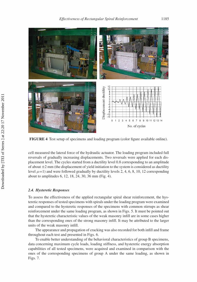
Since the scope of this study was to compare the shear reinforcement type with referenceto masonry infill type, an arbitrarily selected quasi-static reversed cyclic lateral load andan axial compressive load per column were applied. The test setup is shown in Fig. 4. Thelateral load was applied by means of a double action hydraulic actuator. The vertical loadswere exerted by manually controlled hydraulic jacks that were tensioning four strands atthe top of the column whose forces were maintained constant during each test. The levelof this axial compressive load per column was set 50 kN (0.1 of the ultimate). The axialforce applied to the columns of 50 kN was considered to prevent the columns from devel-oping tension, as shown from the moment-thrust interaction diagram for the columns ofthe frame. Besides, axial force was dictated by the availability of the formwork and thelaboratory testing capacities. One LVDT measured the lateral drift of the frame and a load
Dow
nloa
ded
by [
TE
I of
Ser
res
] at
22:
20 1
7 N
ovem
ber
2011
Effectiveness of Rectangular Spiral Reinforcement 1185
FIGURE 4 Test setup of specimens and loading program (color figure available online).
cell measured the lateral force of the hydraulic actuator. The loading program included fullreversals of gradually increasing displacements. Two reversals were applied for each dis-placement level. The cycles started from a ductility level 0.8 corresponding to an amplitudeof about ±2 mm (the displacement of yield initiation to the system is considered as ductilitylevel μ=1) and were followed gradually by ductility levels 2, 4, 6, 8, 10, 12 correspondingabout to amplitudes 6, 12, 18, 24, 30, 36 mm (Fig. 4).
2.4. Hysteretic Responses
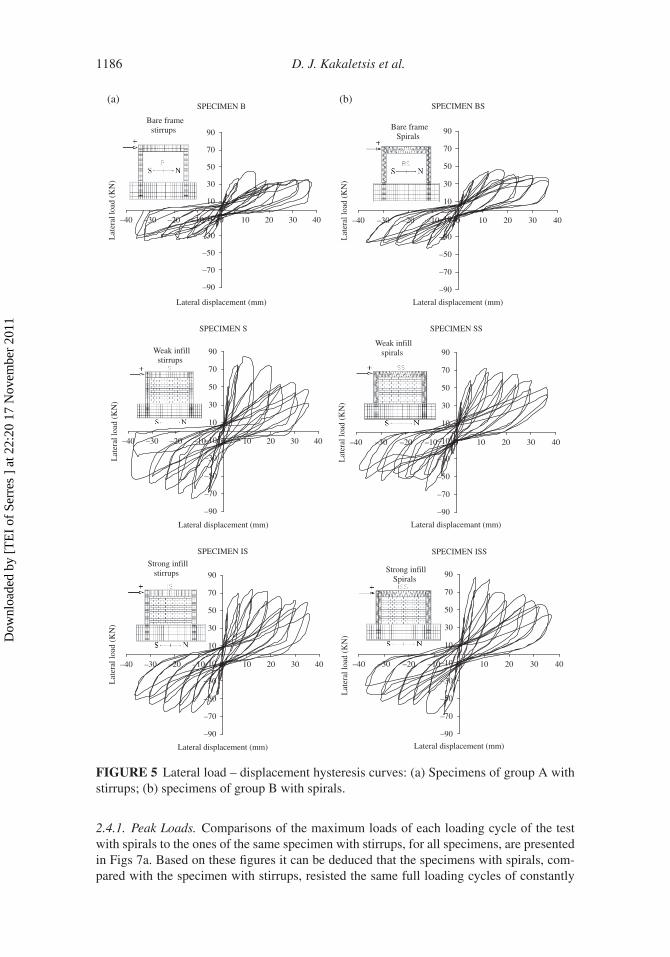
To assess the effectiveness of the applied rectangular spiral shear reinforcement, the hys-teretic responses of tested specimens with spirals under the loading program were examinedand compared to the hysteretic responses of the specimens with common stirrups as shearreinforcement under the same loading program, as shown in Figs. 5. It must be pointed outthat the hysteretic characteristic values of the weak masonry infill are in some cases higherthan the corresponding ones of the strong masonry infill. It may be attributed to the largerunits of the weak masonry infill.
The appearance and propagation of cracking was also recorded for both infill and framethroughout each test and presented in Figs. 6.
To enable better understanding of the behavioral characteristics of group B specimens,data concerning maximum cycle loads, loading stiffness, and hysteretic energy absorptioncapabilities of all tested specimens, were acquired and examined in comparison with theones of the corresponding specimens of group A under the same loading, as shown inFigs. 7.
Dow
nloa
ded
by [
TE
I of
Ser
res
] at
22:
20 1
7 N
ovem
ber
2011
1186 D. J. Kakaletsis et al.
SPECIMEN B
–90
–70
–50
–30
–10
10
30
50
70
90
(a) (b)
–40 –30 –20 –10 0 10 20 30 40
Lateral displacement (mm)
Lat
eral
load
(Κ
Ν)
Bare framestirrups
SPECIMEN BS
–90
–70
–50
–30
–10
10
30
50
70
90
–40 –30 –20 –10 0 10 20 30 40
Lateral displacement (mm)
Lat
eral
load
(Κ
Ν)
Bare frame Spirals
SPECIMEN S
–90
–70
–50
–30
–10
10
30
50
70
90
–40 –30 –20 –10 0 10 20 30 40
Lateral displacement (mm)
Lat
eral
load
(Κ
Ν)
Weak infillstirrups
SPECIMEN SS
–90
–70
–50
–30
–10
10
30
50
70
90
–40 –30 –20 –10 0 10 20 30 40
Lateral displacemant (mm)
Lat
eral
load
(Κ
Ν)
Weak infillspirals
SPECIMEN IS
–90
–70
–50
–30
–10
10
30
50
70
90
–40 –30 –20 –10 0 10 20 30 40
Lateral displacement (mm)
Lat
eral
load
(Κ
Ν)
Strong infillstirrups
SPECIMEN ISS
–90
–70
–50
–30
–10
10
30
50
70
90
–40 –30 –20 –10 0 10 20 30 40
Lateral displacement (mm)
Lat
eral
load
(Κ
Ν)
Strong infillSpirals
FIGURE 5 Lateral load – displacement hysteresis curves: (a) Specimens of group A withstirrups; (b) specimens of group B with spirals.
2.4.1. Peak Loads. Comparisons of the maximum loads of each loading cycle of the testwith spirals to the ones of the same specimen with stirrups, for all specimens, are presentedin Figs 7a. Based on these figures it can be deduced that the specimens with spirals, com-pared with the specimen with stirrups, resisted the same full loading cycles of constantly
Dow
nloa
ded
by [
TE
I of
Ser
res
] at
22:
20 1
7 N
ovem
ber
2011

Effectiveness of Rectangular Spiral Reinforcement 1187
(a)
(e)
(c)
(b)
(f)
(d)
FIGURE 6 Photographs of distress and failure modes of specimens with stirrups or spirals:(a), (b) bare frames B, BS; (c), (d) weak solid infill S, SS; (e), (f) strong solid infill IS, ISS(color figure available online).
increasing displacement, almost without any significant loss of their strength. Furthermore,it is also observed that the specimens with spirals BS and ISS exhibit higher maximumloading cycle response values than the corresponding specimens with stirrups B and IS.Especially for specimen with spirals SS it has noted an insignificant loss of strength at 1stuntil 7th loading cycles and a slight load drop can be seen at the load-displacement envelopversus specimen with stirrups S. Table 4 shows the ratio of the response loads of specimenswith stirrups over the response loads of the corresponding specimens with spirals for thefirst loading cycles of all tested specimens.
Dow
nloa
ded
by [
TE
I of
Ser
res
] at
22:
20 1
7 N
ovem
ber
2011

1188 D. J. Kakaletsis et al.
(a)
BARE FRAME
-90
-70
-50
-30
-10
10
30
50
70
90
-40 -35 -30 -25 -20 -15 -10 -5 0 5 10 15 20 25 30 35 40
Lateral Displacement δ (mm)
Lat
eral
Loa
d (k
N)
SPIRALS - SPECIMEN BS
STIRRUPS - SPECIMEN Β
SPIRALS - SPECIMEN BS
STIRRUPS - SPECIMEN Β
SPIRALS - SPECIMEN BS
STIRRUPS - SPECIMEN Β
FRAME WITH WEAK INFILL
-90
-70
-50
-30
-10
10
30
50
70
90
-40 -35 -30 -25 -20 -15 -10 -5 0 5 10 15 20 25 30 35 40
Lateral Displacement δ (mm)
Lat
eral
Loa
d V
(kN
)
SPIRALS - SPECIMEN SS
STIRRUPS - SPECIMEN S
FRAME WITH STRONG INFILL
-90
-70
-50
-30
-10
10
30
50
70
90
-40 -35 -30 -25 -20 -15 -10 -5 0 5 10 15 20 25 30 35 40
Lateral Displacement δ (mm)
Lat
eral
Loa
d V
(kN
)
SPIRALS - SPECIMEN ISS
STIRRUPS - SPECIMEN IS
(b)BARE FRAME
0
2
4
6
8
10
12
14
16
18
20
22
24
0 5 10 15 20 25 30 35 40
Lateral Displacement δ (mm)
Stif
fnes
s Κ
(kN
/mm
)
FRAME WITH WEAK INFILL
0
2
4
6
8
10
12
14
16
18
20
22
24
0 5 10 15 20 25 30 35 40
Lateral Displacement δ (mm)
Stif
fnes
s K
(kN
/mm
)
FRAME WITH STRONG INFILL
0
2
4
6
8
10
12
14
16
18
20
22
24
0 5 10 15 20 25 30 35 40
Lateral Displacement δ (mm)
Stif
fnes
s K
(kN
/mm
)(c)
BARE FRAME
0100020003000400050006000700080009000
1000011000120001300014000
0 1 2 3 4 5 6 7 8 9 10 11 12 13 14
Loading Cycles
Cum
ulat
ive
Ene
rgy
ΣWi
(KN
*mm
)
SPIRALS - SPECIMEN SS
STIRRUPS - SPECIMEN S
SPIRALS - SPECIMEN ISS
STIRRUPS - SPECIMEN IS
FRAME WITH WEAK INFILL
0100020003000400050006000700080009000
1000011000120001300014000
0 1 2 3 4 5 6 7 8 9 10 11 12 13 14
Loading Cycles
Cum
ulat
ive
Ene
rgy
ΣWi
(KN
*mm
)
FRAME WITH STRONG INFILL
0100020003000400050006000700080009000
1000011000120001300014000
0 1 2 3 4 5 6 7 8 9 10 11 12 13 14
Loading Cycles
Cum
ulat
ive
Ene
rgy
ΣWi
(KN
*mm
)
SPIRALS - SPECIMEN SS
STIRRUPS - SPECIMEN S
SPIRALS - SPECIMEN ISS
STIRRUPS - SPECIMEN IS
FIGURE 7 Comparison of responses between specimens with stirrups and specimens withspirals: (a) load-displacement envelops; (b) stiiffnesses; (c) energy dissipation capacities(color figure available online).
2.4.2. Stiffness. The effectiveness of the examined continuous rectangular spiral reinforce-ment in the stiffness of specimens is evaluated by studying the loading stiffness of allloading cycles. Thus, values of the loading tangent stiffness were measured in the testsboth for specimens with spirals and specimens with stirrups for all loading cycles, as pre-sented in Fig. 7b. The ratios of the measured loading stiffness of the specimens with stirrupsover the stiffness of the corresponding specimens with spirals for the first loading cycles ofall tested specimens are presented in Table 4. Thus, it can be seen that for the specimenswith spirals BS and ISS the loading stiffness was restored satisfactorily achieving similaror higher stiffness levels to the corresponding specimens with stirrups B and IS. Especiallyfor specimen with spirals SS it has noted an insignificant loss of stiffness at 1st until 7thloading cycles versus specimen with stirrups S. This may be attributed to the higher levelof initial damage of the specimen SS.
2.4.3. Hysteretic Energy Adsorption. In order to ascertain the hysteretic energy absorptioncapabilities of test specimens with spirals, the energy dissipated per cycle, in terms of the
Dow
nloa
ded
by [
TE
I of
Ser
res
] at
22:
20 1
7 N
ovem
ber
2011

Effectiveness of Rectangular Spiral Reinforcement 1189
area of the response loading cycle is used, both for specimens with spirals and specimenswith stirrups. The ratios of the measured energy absorption of the specimens with stirrupsover the energy absorption of the corresponding specimens with spirals are presented inTable 4. Based on these values, it can be deduced that the energy absorption capabilityof all specimens with spirals appears to have decreased during almost all loading cycles,in comparison with the ones of the corresponding specimens with stirrups. The smallerdissipated energy may derive from the fact that a deterioration in one part of the spiral caninfluence the adjacent zones, due to lack of anchoring. This phenomenon has been noted inthe past for circular spirals too.
As shown in Fig. 7c and Table 4, the contribution of spirals to energy dissipationcapacity of the system seems to be slightly greater than the contribution of stirrups, onlyat very high distortions and only in bare frame and frame with strong infill. For thesespecimens the slight improvement of the energy absorption capability of the loading cyclesafter a drift of about γ=20‰ (7th cycle), compared to the corresponding specimens withstirrups, could be hardly attributed mainly to the higher rate deterioration the specimenwith stirrups exhibit during the loading sequence.
2.4.4. Failure Modes. In order to investigate whether the applied rectangular spiral shearreinforcement alters the character of the infilled frame failure, observed failure modes ofboth specimens with stirrups and specimens with spirals are examined and compared toeach other.
Specimens “B” and “BS” were bare reference frames. Flexural cracks and correspond-ing plastic hinges occurred at predicted critical locations at the bottom and the top of thecolumns and the ends of the beam — at a drift 4–6‰(Figs. 6a, b).
Specimens “S”, “SS” and “IS”, “ISS” had solid weak and solid strong infill, respec-tively. The nonlinear behavior was initiated by the cracking of the infill. Then plastic hingesdeveloped at the top and the bottom of the columns — at a drift 4–11‰. However, as shownby the damage patterns of specimens, the failure of the specimens “S” and “SS” with theweak solid infill (Figs. 6c, d) was dominated by internal crushing in the infill — at a drift19‰ — while the failure of the specimens “IS” and “ISS” with the strong solid infill(Figs. 6e, f) was dominated by sliding of the infill along its bed joints — at a drift 14‰.
In all infilled specimens the cracking of the beam occurred far from the column facetowards the mid-span vicinity of the beam. Plastic hinges were developed at drifts higherthan 11‰ or they did not developed at all. Generally, the infills restrained the beams frombending and, there by, postpone the development of plastic hinges in the beams. In the caseof the present project, shear failure of the columns was not observed.
It can be seen that the examined shear reinforcement does not alter the character of thefailure behavior of the bare and infilled frames.
2.4.5. Other Response Data. The initial stiffnesses, critical loads, energy dissipationcapacities, and critical displacements attained during the tests of the six specimens werederived. It must be pointed out that the hysteretic characteristics of the weak masonry infillwere some times larger because of the larger net bedded area for the weak masonry units.From the data shown in Table 3 the following can be concluded.
For all cases lateral resistance (v) of infilled frames was from 1.63 up to 1.94 timesthat of the corresponding bare frames. Spirals increased resistance as far strong infills only.The residual resistance (βres) was observed to be increased in the case of strong infills.Spirals did not influenced very much residual resistance. The presence of strong infillsincreased considerably the initial stiffness (k) of the system. Spirals decreased the initialstiffness. It should be noted that the confinement type of the surrounding frame members,
Dow
nloa
ded
by [
TE
I of
Ser
res
] at
22:
20 1
7 N
ovem
ber
2011

TAB
LE
3C
ompa
riso
nof
resp
onse
data
for
test
spec
imen
sve
rsus
shea
rre
info
rcem
entt
ype
(a)
Spec
.St
ruct
ural
mor
phol
ogy
vγ
y(‰
)γ
u(‰
)k
v lim
μ0,
85β
res
V2/V
1(m
.v.)
W2/W
1(m
.v.)
�W
/�
WB
BB
are
fram
est
irru
ps1.
005.
0612
.09
1.00
0.74
2.81
1.00
0.89
0.84
1.00
SW
eak
infil
lst
irru
ps1.
842.
829.
232.
880.
654.
241.
400.
870.
851.
64
ISSt
rong
infil
lst
irru
ps1.
653.
1013
.69
3.04
0.84
6.31
1.75
0.87
0.70
1.48
(b)
Spec
.St
ruct
ural
mor
phol
ogy
vγ
y(‰
)γ
u(‰
)k
v lim
μ0,
85β
res
V2/V
1(m
.v.)
W2/W
1(m
.v.)
�W
/�
WB
S
BS
Bar
efr
ame
spir
als
1.00
3.44
15.5
01.
000.
543.
971.
000.
900.
701.
00
SSW
eak
infil
lsp
iral
s1.
632.
7713
.33
1.92
0.51
4.09
1.47
0.87
0.79
1.46
ISS
Stro
ngin
fill
spir
als
1.94
3.33
6.81
2.36
0.65
3.36
1.56
0.87
0.70
1.44
v:L
ater
alno
rm.
resi
stan
ce,β
res:
Res
idua
lno
r.re
sist
ance
,γ
y:
Serv
icea
bilit
ylim
it,γ
u:
Ulti
mat
elim
it,k:
In.
norm
.st
iffn
ess,
μ0,
85:
Duc
tility
fact
or,�
W:
cum
ulat
ive
ener
gy,V
:max
.Rec
orde
dfo
rce,
W:E
nerg
ydi
ssip
atio
n,1/
2:1st
/2nd
cycl
e.
1190
Dow
nloa
ded
by [
TE
I of
Ser
res
] at
22:
20 1
7 N
ovem
ber
2011

Effectiveness of Rectangular Spiral Reinforcement 1191
TABLE 4 Comparison of response ratios (frame with stirrups/frame with spirals)
Loads ratio
Cycles
Specimen 1st 3rd 5th 7th 9th 11th 13th Mean value
B/BS 1.06 1.11 0.97 0.79 0.80 0.91 0.96 0.94S/SS 1.09 1.29 1.08 1.05 0.80 0.91 0.91 1.02IS/ISS 1.19 0.79 0.87 1.01 0.94 0.99 1.07 0.98
Stiffness ratio
Cycles
Specimen 1st 3rd 5th 7th 9th 11th 13th Mean value
B/BS 1.06 0.93 0.84 0.78 0.74 0.88 0.94 0.88S/SS 1.15 1.29 1.06 1.13 0.80 0.91 0.93 1.04IS/ISS 1.16 0.75 0.84 0.96 1.02 0.96 1.11 0.97
Energy ratio
Cycles
Specimen 1st 3rd 5th 7th 9th 11th 13th Mean value
B/BS 0.77 1.41 1.52 0.80 0.70 1.06 0.78 1.01S/SS 0.80 1.65 2.01 1.19 0.94 1.15 1.13 1.27IS/ISS – 1.05 1.13 0.96 1.02 1.04 0.98 1.03
did not influence considerably the limit states which had been regarded corresponding tothe drifts (γ y) and (γ u). Only the specimen with strong infill of group B had ultimate limitoccurring at a much lower drift level than that of group A. The presence and behavior ofspirals increased the ductility factor (μ0,85), corresponding to a lateral force response equalto 85% of the maximum, only in the bare frame while the specimens with infills exhibitedhigher ductility than that of the bare frames. The total energy dissipation capacity (�W) ofthe infilled frames was of order 1,44 up to 1,64 times the capacity of the corresponding bareframes. It must be pointed out that infill strength and type of shear reinforcement did notgreatly influence the values of dissipation ratio. Specimens with strong infills and spiralsseemed to loose a larger amount of strength and energy during the second loading cycle.
3. Conclusions
The authors have carried out investigations on several bare frames and infilled frames withweak and strong infills that were sorted into two groups based on the shear reinforcement,providing data for a parametric evaluation of different shear reinforcement and differentinfill compressive strengths. Despite the inherent weakness, that results from the smallnumber of specimens tested, that is particularly true for specimens with infills, due to thevariability of masonry and the contact between infill and frame, the following conclusionsconcerning the applied shear reinforcement with reference to the strength of the masonryinfill could be drown from the test reported herein.
Dow
nloa
ded
by [
TE
I of
Ser
res
] at
22:
20 1
7 N
ovem
ber
2011

1192 D. J. Kakaletsis et al.
a. The character of the failure behavior of the bare and infilled frames was a ductileflexural one, no matter of infill’s compressive strength and frame’s shear reinforce-ment type. Rectangular spirals were found to be as efficient in preventing concretebrittle shear failure as traditional stirrups.
b. If the lateral load capacity of all specimens is compared, it can be said that lateralload capacity has only slightly increased with reinforcing by spirals. The meanresponse load ratio (frame with stirrups / frame with spirals) for bare frame andinfilled frame specimens is 0.98.
c. If a comparison is to be made for initial stiffness between specimens with transversesteel in the form of common stirrups and those with continuous rectangular spiralreinforcement of the same spacing, it should be pointed out that all specimens havevery close mean response stiffness ratio (frame with stirrups/frame with spirals)with a mean value of 0.96.
d. It is obvious that the use of spirals by any type of frame specimen has decreasedenergy dissipation. Nevertheless, energy dissipation capacity has the biggest degra-dation with infilling by a weak infill panel. The mean response energy ratio (framewith stirrups / frame with spirals) for all specimens is 1.10, against 1.27 for infilledframe specimens with weak infill, because those specimens developed a moreadverse crack system than the others.
e. Even if these disadvantages of rectangular spiral reinforcement, that was notobserved to offer a clear total improvement of the response of specimens, areignored, it is also clear that the economical and practical feasibility of the solution islimited by additional execution difficulties of spiral reinforcement.
f. Furthermore, some evident lower performances, in particular concerning energydissipation, have been shown. In fact, the failure in one point can render uselessthe efficiency of the whole transverse reinforcement. Therefore, it is emphasizedthe necessity of a deeper knowledge for continuous spirals, even rectangular, byinvestigating the effects of different variables on the behaviour of frames, such asamount of lateral steel, lateral steel spacing, specimen size, and by critically exam-ining code requirements for circular spirals, related to the minimum volumetric ratioof spiral reinforcement, and the maximum spiral pitch, in the case they could applyfor rectangular spirals too.
g. Finally, taking into account all the involved uncertainties, the scale effects and theinadequate number of samples for each specimen, it has to be emphasized that theexperimental results of the presented work and the above yielded conclusions aremainly limited to the study cases and must be used and extrapolated carefully andcautiously. It is recommended that more refined experimental techniques be pursuedin future research.
Acknowledgments
The authors would like to thank the Research Committee of Technological EducationalInstitution of Serres for funding of this research project with ID: SAT/CE/59/15/1-/2-2010/6.
References
CEB Comite Euro-International du Beton [1996] RC Frames under Earthquake Loading – Stateof the art report. Chapter 5: Reinforced Concrete Infilled frames, Thomas Telford, London, pp.231–303.
Dow
nloa
ded
by [
TE
I of
Ser
res
] at
22:
20 1
7 N
ovem
ber
2011

Effectiveness of Rectangular Spiral Reinforcement 1193
CEN European Standard EN 998-2 [2001] Specification for Mortar for Masonry, EuropeanCommittee for Standardization, Brussels, pp. 1–17.
CEN European Standard EN 1998-1 [2004] Eurocode 8: Design of Structures for EarthquakeResistance, Part 1: General Rules, Seismic Actions and Rules for Buildings, Comite Europeende Normalisation, Brusells.
Fardis, M. N. [2000] “ Design provisions for masonry – infilled RC frames,” 12th World Conferenceon Earthquake Engineering, Auckland, New Zealand, Paper 2553.
Fardis, Michael N. [2009] Seismic Design, Assessment and Retrofitting of Concrete Buildings,based on EN-Eurocode 8, Series: Geotechnical, Geological, and Earthquake Engineering, Vol.8, Springer, New York.
Fardis, M. N. and Panagiotakos, T. B. [1997] “Seismic design and response of bare and masonry-infilled reinforced concrete buildings. Part II: Infilled structures,” Journal of EarthquakeEngineering 1(3), 475–503.
FEMA 356 [2000] Prestandard and Commentary for the Seismic Rehabilitation of Buildings. Chapter7: Masonry, Washington, D.C., pp. 7.23–7.29.
Kakaletsis, D. J. [2007] “Influence of masonry strength and rectangular spiral shear reinforcementon infilled R/C frames under cycling loading,” Proc. of Thirteenth International Conferenceon Computational Methods and Experimental Measurements (CMEM 2007), Prague, CzechRepublic, pp. 643–653.
Kakaletsis, D. J. and Karayannis, C. G. [2008] “Influence of masonry strength and openings oninfilled R/C frames under cycling loading,” Journal of Earthquake Engineering, 12(2), 197–221.
Karayannis, C. G., Sirkelis, G. M., and Mavroeidis, P. [2005] “Improvement of seismic capac-ity of external beam-column joints using rectangular spiral shear reinforcement,” Proc. of theFifth International Conference on Earthquake Resistant Engineering Structures, Wessex Instituteof Technology, University of Patras, Aristotele University of Thessaloniki, National TechnicalUniversity of Athens, Skiathos, pp. 147–156.
Moghaddam, H. A. and Dowling, P. J. [1987] “The state of the art in infilled frames,” CivilEngineering Department, Imperial College, ESEE Research Report No, 87-2, London, pp.231–284.
Park, R. and Paulay, T. [1975] Reinforced Concrete Structures, John Wiley & Sons, New York.
Dow
nloa
ded
by [
TE
I of
Ser
res
] at
22:
20 1
7 N
ovem
ber
2011