effects of bell mouth geometries on the flow rate of …€¦ · · 2016-10-20effects of bell...
TRANSCRIPT

Journal of Mechanical Science and Technology 25 (9) (2011) 2267~2276
www.springerlink.com/content/1738-494x DOI 10.1007/s12206-011-0609-3
Effects of bell mouth geometries on the flow rate of centrifugal blowers†
Pham Ngoc Son1,*, Jaewon Kim1 and E. Y. Ahn2 1Department of Mechanical Engineering, Sunmoon Graduate School, Asan 336-708, Korea
2Department of Multimedia, Hanbat National University, Daejon 305-719, Korea
(Manuscript received November 7, 2010; Revised May 24, 2011; Accepted May 26, 2011)
----------------------------------------------------------------------------------------------------------------------------------------------------------------------------------------------------------------------------------------------------------------------------------------------
Abstract In the present study, the effects of bell mouth geometries on the flow rate of centrifugal blowers were numerically simulated using a
commercial computational fluid dynamics (CFD) program, FLUENT. A total of 12 numerical models were prepared by combining the different values of bell mouth radii and gaps between the bell mouth and the upper fan case; the cross section of bell mouth was chosen as a circular arc. All models were meshed with hexahedra elements using the Gambit software. The frozen rotor method combined with a realizable k-epsilon turbulence model and nonequilibrium wall function was used to simulate the three-dimensional flow inside the cen-trifugal blowers. CFD investigation showed that the bell mouth radius had a strong effect on the flow rate, which can vary by more than 5% with different bell mouth models, whereas the effect of the gap between the bell mouth and the upper fan case on the flow rate was weaker. On the basis of CFD results, experiments were carried out for five typical bell mouths to verify the effect of the bell mouth radius, the gap between the bell mouth and the upper fan case on the flow rate. CFD results were validated by the good agreement between the CFD results and the parallel experimental results.
Keywords: Bell mouth; Centrifugal blower; CFD; Fan performance ---------------------------------------------------------------------------------------------------------------------------------------------------------------------------------------------------------------------------------------------------------------------------------------------- 1. Introduction
Centrifugal blowers, which are capable of providing moder-ate to high-pressure rise and flow rates, are widely used in different industrial applications, such as air-conditioning sys-tems in buildings and blowers in automotive cooling units, among others.
Centrifugal blowers are composed of four main parts, namely, the casing, impeller, hub, and bell mouth. The role of the bell mouth is to guide the inlet flow and to prevent the back flow from the impeller. Although studies on the casing and impeller are easily available, in-depth studies on the bell mouth of centrifugal blowers are rare.
The effect of inlet geometries on the performance of a squir-rel cage fan has been studied by Montazerin et al. [1]. In their research, the geometries of the inlet, such as the radius and the gap between the inlet and the impeller, were taken into con-sideration. Experiments were carried out for various inlet con-figurations in the cases of the inward and outward inlets using a wind tunnel with laser Doppler anemometry. Finally, the optimum design was achieved on the basis of performance curves and velocity profiles.
At present, most of the experimental works could be re-placed by computational fluid dynamics (CFD) simulation be-cause of the significant progress of computing technology. Thus, a new design process, or CFD-based design process, has been created. Instead of making a real model for experiments, computer models were built using CAD software. CFD pro-grams, such as FLUENT, are used to simulate the flow after the meshing process. Typical models were thereafter prepared to validate the CFD results. The geometries of the model could be easily modified so that a number of models could be simulated to obtain the optimum model without the huge ac-companying expense of research.
Numerous successful studies have been achieved using the CFD-based design process. To optimize the fan design, we created 32 numerical fan models based on the CFD simulation by Lee et al. [2]. This is an improvement over the use of tradi-tional design method which requires a considerable length of time and budget to complete the process. Engin [3] studied the effects of tip clearance in a centrifugal fan using the CFD method. The simulation was performed with a commercial CFD code FLUENT, using a standard k–ε turbulence model, to obtain the complex three-dimensional flow field inside the centrifugal fan. Subsequently, the CFD results were compared with the experimental data. The maximum deviation between CFD and experiments is approximately 5%, which shows the good accuracy of the CFD prediction. Gasparovic and Carno-
† This paper was recommended for publication in revised form by Associate Editor Byeong Rog Shin
*Corresponding author. Tel.: +82 41 543 2337, Fax.: +82 41 530 2659 E-mail address: [email protected]
© KSME & Springer 2011

2268 P. N. Son et al. / Journal of Mechanical Science and Technology 25 (9) (2011) 2267~2276
gurska [4] used CFD simulation to optimize the case of the double-outlet centrifugal fan. The flow field of the original model was simulated using the commercial code FLUENT. The unsteadiness of the flow field was achieved with a sliding mesh method. On the basis of the detail of the flow field ob-tained using CFD simulation, they modified the casing so that the flow will be equally divided between two outlets. The CFD result was again correctly confirmed by experiments. Sharma et al. [5] discussed the relationship between the posi-tion of splitter vanes and the performance of the centrifugal fan. On the basis of the CFD simulation of a two-dimensional model, the static pressure recovery coefficient was improved by optimizing the position of splitter vanes. Huang and Hsieh [6] optimized the design of the blade and volute in a centrifu-gal fan using FLUENT, a commercial CFD software. The shape of the cutoff in the centrifugal fan was also optimized by Han and Maeng [7] using two-dimensional CFD analysis combined with a neural network. The performance curves and the detail of the flow field for each design of cutoff were ob-tained using CFD simulation and subsequently validated by experiments. Finally, neural network analysis was performed to determine the optimal angle and radius of the cutoff.
The present research focuses on finding the effect of bell mouth geometries on the flow rate of centrifugal blowers. The main purposes of the bell mouth are to guide the inlet flow and to prevent the back flow from the impeller. The inefficient design of the bell mouth could result in the reduction of the flow rate of the blower. In the present work, the detail of the flow field around the bell mouth with various geometrical parameters was simulated using the FLUENT software to figure out the effect of bell mouth geometries on flow rate.
2. Numerical method for performance evaluation
2.1 Governing equation
To simplify the problem, several assumptions were pro-posed. First, the flow was assumed to be incompressible. This was validated by the relatively low speed of the flow com-pared with the speed of sound (Mach number was approxi-mately 0.05).
Second, to deal with the turbulence flows inside the cen-trifugal blower, the equations of motion for fluid flow, known as the Reynolds-averaged Navier–Stokes equations (RANS) were time-averaged. Consequently, the continuity and mo-mentum equations for the three-dimensional incompressible flow could be written as follows using the Einstein notation:
• Continuity
(1)
• Momentum
(2)
To close the RANS equations, additional modeling for
Reynolds stress term ' '( )l Ju uρ was required. Among several turbulence models, which were created to calculate the Rey-nolds stress term, the two-equation realizable k-ε turbulence model [8] was selected for this case. The turbulence model, which can provide advanced performance for flows involving rotation, boundary layers under strong adverse pressure gradi-ent, separation, and recirculation, has been successfully ap-plied in CFD for centrifugal blowers, pumps, and compressors, among others. The requirement for computing power to ana-lyze the turbulence model is reasonable, compared with LES or DNS, which normally requires a super computer to run the simulation. The equations of the realizable k–ε turbulence model are written as follows:
Transport equations for turbulence kinetic energy k,
(3)
For turbulence dissipation rate ε ,
(4)
In this equation,
(5)
The eddy viscosity is computed as follows:
(6)
where
(7) The following are the model constants: 1 1.44,C ε = 2 1.9,C = 1.0,kσ = and 1.2.εσ = For the region near the wall, the nonequilibrium wall func-
tion [9] was used to save on computing time. The wall func-tion can provide higher accuracy than standard wall functions in case of separation or reattachment flow, which is often ob-served in flow inside the centrifugal blower. The equations for this wall function have the following form:
(8)
where
(9)
.

P. N. Son et al. / Journal of Mechanical Science and Technology 25 (9) (2011) 2267~2276 2269
2.2 Geometrical models and grid generation
In the present work, the cross section of the bell mouth was chosen as a circular arc. The main parameters of the bell mouth are the following:
- r/R: ratio between the bell mouth radius and the impeller radius.
- h/H: ratio between the distance from the bell mouth center to the upper fan case and the gap between the fan case and the impeller.
These parameters are illustrated in Fig. 1. Table 1 shows that a total of 12 cases were simulated. Table 2 shows the parameters of the impeller. The rotational speed of the impeller is 500 rpm. The geometrical model of the centrifugal blower was de-
signed using Catia V5 R17. The inlet and the outlet regions of centrifugal blowers were extended 10 times their diameters with the purpose of preventing back flow and creating uni-form velocity profile at inlet and outlet.
The Catia models shown in Fig. 3 were subsequently im-ported to perform meshing using Gambit Version 2.4.6 soft-ware. As for the meshing elements, hexahedra were chosen over tetrahedra because hexahedra elements tend to have higher accuracy than tetrahedra in the case of equal meshing number. In particular, when the mesh is aligned with the flow, the hexahedra, even with a lower number of elements can
achieve higher accuracy than the tetrahedra. For regions with complicated geometry such as the impeller,
bell mouth, or casing, obtaining a high quality of structured mesh is impossible; hence, unstructured mesh was applied. For simple geometry regions such as the inlet and outlet, structured mesh were preferred to improve the accuracy and to reduce calculating time.
For monitoring the mesh quality, two main parameters of gambit were proposed: equal size skewness and equal size angle. The mesh quality in the casing, bell mouth, and the inlet and the outlet regions was approximately 0.61, which indi-cates good mesh quality. The mesh quality in the impeller
Table 1. Cases of CFD simulation (all units in mm). r/R h/H
6% (10/155)
9% (14/155)
11% (17.5/155)
6% (0.5/8.5) Case 1* Case 5 Case 9
29% (2.5/8.5) Case 2 Case 6 Case 10
53%.(4.5/8.5) Case 3 Case 7 Case 11
71% (6/8.5) Case 4 Case 8 Case 12
*Running model in the market.
Table 2. Impeller specifications.
Impeller OD (mm)
Impeller ID (mm) Blade number Blade outer angle (°)
310 256 48 156
Fig. 1. Parameters of the bell mouth.
Fig. 2. Front view of the blower.
Fig. 3. Casing draft and guide vanes.
Fig. 4. Full model meshing (includes inlet and outlet).

2270 P. N. Son et al. / Journal of Mechanical Science and Technology 25 (9) (2011) 2267~2276
region was 0.75 because of its complex nature. This is worse than the mesh quality in other regions but still an acceptable value.
To assure the mesh independence of CFD solution, we car-ried out a mesh refinement test as a model (r/R = 9%, h/H = 6%). The inlet mass flow rate was fixed at 0.21 kg/s (flow rate coefficient φ = 0.28). The size of the hexahedra elements was
reduced (except for the boundary layer cells) to increase the number of the meshing element (Fig. 8).
After 1,400,000, the difference between CFD solutions was negligible; hence, no further meshing refinement was needed.
Table 4 shows the grid number for each region of chosen mesh.
2.3 Solver setting and boundary conditions
Quasi-steady flow field simulations have been performed using multiple rotating reference frames or “frozen rotor” [10]. To achieve the steady state simulation, we applied a rotating reference frame to the rotating region around the impeller with the same rotation speed as that of the impeller. A fixed refer-ence frame was applied to static regions. The nonconformal interfaces were used for the interfaces between static and ro-tating regions.
The inlet boundary condition was chosen as the mass flow inlet (mass flow rate was fixed at inlet). The outlet boundary condition was selected as the pressure outlet [11], which was set at atmospheric pressure. For wall condition, the no-slip wall condition was applied. The inlet and the outlet were ex-tended 10 times their diameter to ensure a fully developed flow at the inlet and outlet regions (as shown in Fig. 4).
The couple solver and the second-order upwind discretiza-
Table 3. Dependence of Y+ value on grid number.
Grid number (million) 1.12 1.25 1.42 1.61 1.83
Y+ min 35.1 34.8 32.7 30.6 28.6
Y+ max 225 222 221 218 219
Table 4. Grid number of chosen mesh.
Case Impeller Bell mouth Inlet Outlet
Number of element 268412 470070 11872 281475 404613
Mesh quality* 0.62 0.75 0.56 0.59 0.50
* “Equal angle skewness,” checked by the Gambit program. The best value is 0 whereas the worst is 1. In most cases, the acceptable value is less than 0.9.
Fig. 8. Dependence of static pressure rise on grid number.
Fig. 5. Casing meshing with all hexahedra elements.
Fig. 6. Close-up of the meshing region between the bell mouth and thecasing.
Fig. 7. Unstructured hexahedra meshing of the impeller region.
P. N. Son et al. / Journal of Mechanical Science and Technology 25 (9) (2011) 2267~2276 2271
tion scheme were used to ensure the fast convergence and high accuracy solutions.
The convergence criterion was set at 10-3 for all residuals. In addition to the monitoring of residuals, the levels of static pressure at the inlet and outlet were checked every cycle. To ensure the true convergence of the solution, we ended the simulation when the change in static pressure was less than 0.1% or when a periodical change in pressure was observed.
A total of 96 cases (12 models with 8 points for each model) were simulated using an eight-core 3 GHz work sta-tion with 16 GB RAM. Approximately 30 days were needed to finish all simulations.
3. CFD results
3.1. Nondimensional parameters
All the parameters of the performance of centrifugal blow-ers were normalized as follows:
- Flow rate coefficient
(10)
- Pressure coefficient
(11)
- Power coefficient
(12)
- Static efficiency
(13)
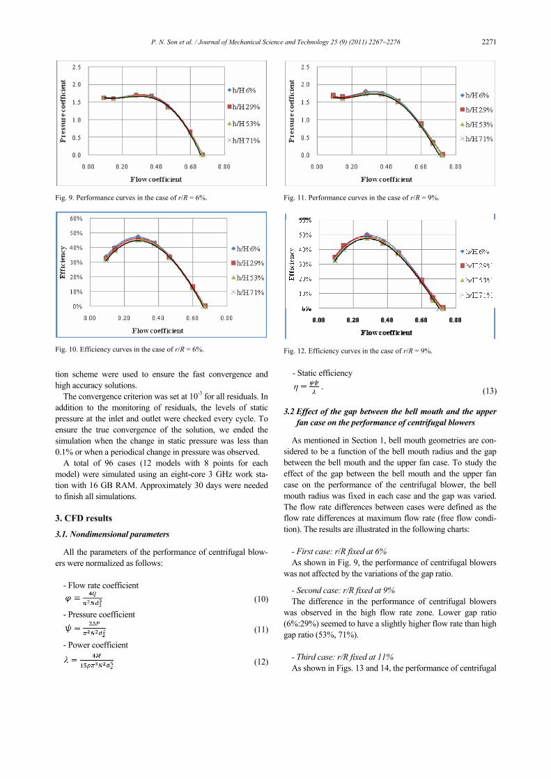
3.2 Effect of the gap between the bell mouth and the upper fan case on the performance of centrifugal blowers
As mentioned in Section 1, bell mouth geometries are con-sidered to be a function of the bell mouth radius and the gap between the bell mouth and the upper fan case. To study the effect of the gap between the bell mouth and the upper fan case on the performance of the centrifugal blower, the bell mouth radius was fixed in each case and the gap was varied. The flow rate differences between cases were defined as the flow rate differences at maximum flow rate (free flow condi-tion). The results are illustrated in the following charts:
- First case: r/R fixed at 6% As shown in Fig. 9, the performance of centrifugal blowers
was not affected by the variations of the gap ratio.
- Second case: r/R fixed at 9% The difference in the performance of centrifugal blowers
was observed in the high flow rate zone. Lower gap ratio (6%:29%) seemed to have a slightly higher flow rate than high gap ratio (53%, 71%).
- Third case: r/R fixed at 11% As shown in Figs. 13 and 14, the performance of centrifugal
Fig. 9. Performance curves in the case of r/R = 6%.
Fig. 10. Efficiency curves in the case of r/R = 6%.
Fig. 11. Performance curves in the case of r/R = 9%.
Fig. 12. Efficiency curves in the case of r/R = 9%.
2272 P. N. Son et al. / Journal of Mechanical Science and Technology 25 (9) (2011) 2267~2276
blowers was not affected as the gap ratio varied.
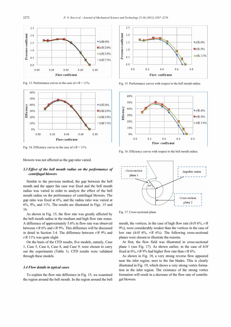
3.3 Effect of the bell mouth radius on the performance of centrifugal blowers
Similar to the previous method, the gap between the bell mouth and the upper fan case was fixed and the bell mouth radius was varied in order to analyze the effect of the bell mouth radius on the performance of centrifugal blowers. The gap ratio was fixed at 6%, and the radius ratio was varied at 6%, 9%, and 11%. The results are illustrated in Figs. 15 and 16.
As shown in Fig. 15, the flow rate was greatly affected by the bell mouth radius in the medium and high flow rate zones. A difference of approximately 5.6% in flow rate was observed between r/R 6% and r/R 9%. This difference will be discussed in detail in Section 3.4. The difference between r/R 9% and r/R 11% was quite slight.
On the basis of the CFD results, five models, namely, Case 1, Case 5, Case 6, Case 8, and Case 9, were chosen to carry out the experiments (Table 1). CFD results were validated through these models.
3.4 Flow details in typical cases
To explain the flow rate difference in Fig. 15, we examined the region around the bell mouth. In the region around the bell
mouth, the vortices, in the case of high flow rate (h/H 6%, r/R 9%), were considerably weaker than the vortices in the case of low rate (h/H 6%, r/R 6%). The following cross-sectional planes were chosen to illustrate the reasons.
At first, the flow field was illustrated in cross-sectional plane 1 (see Fig. 17). As shown earlier, in the case of h/H fixed at 6%, r/R 9% had higher flow rate than r/R 6%.
As shown in Fig. 18, a very strong reverse flow appeared near the inlet region, next to the fan blades. This is clearly illustrated in Fig. 19, which shows a very strong vortex forma-tion in the inlet region. The existence of the strong vortex formation will result in a decrease of the flow rate of centrifu-gal blowers.
Fig. 13. Performance curves in the case of r/R = 11%.
Fig. 14. Efficiency curves in the case of r/R = 11%.
Fig. 15. Performance curves with respect to the bell mouth radius.
Fig. 16. Efficiency curves with respect to the bell mouth radius.
Fig. 17. Cross-sectional plane.

P. N. Son et al. / Journal of Mechanical Science and Technology 25 (9) (2011) 2267~2276 2273
In Figs. 20 and 21, the vortex was also observed under the bell mouth region but was significantly weaker than that in Figs. 18 and 19. As a consequence, the flow was less dis-turbed than the previous case. Thus, the flow rate of this case should be higher than that of the previous case.
Figs. 22 and 23 show the detail of the flow field in cross-sectional plane 2.
Fig. 22 shows a strong reverse flow right under the bell mouth region. The inlet flow was strongly disturbed in this region. A strong vortex formation can be easily observed in Fig. 23, which shows the contours of vorticity under the bell
Fig. 18. Flow detail in the case of h/H 6% and r/R 6%.
Fig. 19. Contours of vorticity in the case of h/H 6% and r/R 6%.
Fig. 20. Flow detail in the case of h/H 6% and r/R 9%.
Fig. 21. Contours of vorticity in the case of h/H 6% and r/R 9%.
Fig. 22. Flow detail in the case of h/H 6% and r/R 6%.
Fig. 23. Contours of vorticity in the case of h/H 6% and r/R 6%.

2274 P. N. Son et al. / Journal of Mechanical Science and Technology 25 (9) (2011) 2267~2276
mouth region. The appearance of this vortex would result in the loss of the flow rate of centrifugal blowers.
The vortex that appeared in Fig. 25 was much weaker than that in Fig. 24.
The reason for the low flow rate in case of h/H 6% and r/R 6% was the appearance of a very strong vortex near the inlet region, next to the fan blades.
4. Experiments
Fig. 26 shows the experiments that have been carried out for the five typical models.
The static pressure and the volume flow rate of centrifugal blowers could be determined by the following equations:
- Static pressure is equal to Pa value - Volume flow rate was calculated from the difference be-
tween Pb and Pc as follows: Q = Cd(Pc-Pb) (m3/min). (14) The Cd value depends on the diameter of the nozzle (Table
5). If several nozzles are used, then the flow rate is equal to the
summation of all the flow rates of the used nozzles. The maximum flow rate of centrifugal blowers was con-
firmed by fully opening the throttle and adjusting the exhaust fan so that the pressure difference (Pc-Pb) was equal to zero. Subsequently, the maximum flow rate was calculated using Eq. (14). This was followed by the gradual closing of the throttle to obtain the performance chart of centrifugal blowers.
Comparisons between experimental and CFD data are illus-trated in the following sections.
4.1 Comparing CFD and experiment in the cases of r/R 9%
and h/H 6%
The difference between CFD and experimental data was approximately 4%, approximately as illustrated in Fig. 27. The CFD data seemed to be less accurate in the very low flow rate region (stall region) or in the very high flow rate region (near the free delivery region).
4.2 Comparing the effects of the bell mouth radius
The gap ratio h/H was fixed at 6%, whereas the bell mouth
Fig. 24. Flow detail in the case of h/H 6% and r/R 9%.
Fig. 25. Contours of vorticity in the case of h/H 6% and r/R 9%.
Table 5. Volume flow rate and nozzle diameters.
D (mm) 50 50.2 74.9 75.1 104.9
Cd 0.466 0.461 1.066 1.061 2.470 Range
(m3/min) 1.7-5 1.7-5 6-10 6-10 11-20
Fig. 26. Fan tester.
Fig. 27. Performance curves derived from data of experiment and CFD.
P. N. Son et al. / Journal of Mechanical Science and Technology 25 (9) (2011) 2267~2276 2275
radius r/R varied from 6% to 11%. In Fig. 28, the smallest radius ratio (6%) had the lowest
flow rate, whereas the 9% radius had the highest flow rate. The flow rate difference between r/R 6% and r/R 9% was approximately 4.4% in the experimental results and 5.6% in the CFD results. The difference between radius ratio 9% and 11% was quite slight in both experiments and CFD simulation.
In this case, the CFD and experimental results are in good agreement.
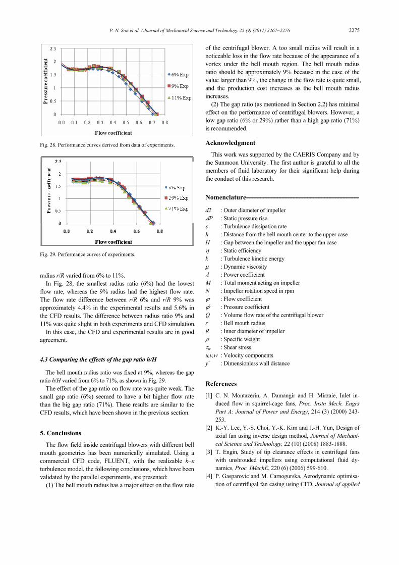
4.3 Comparing the effects of the gap ratio h/H
The bell mouth radius ratio was fixed at 9%, whereas the gap ratio h/H varied from 6% to 71%, as shown in Fig. 29.
The effect of the gap ratio on flow rate was quite weak. The small gap ratio (6%) seemed to have a bit higher flow rate than the big gap ratio (71%). These results are similar to the CFD results, which have been shown in the previous section.
5. Conclusions
The flow field inside centrifugal blowers with different bell mouth geometries has been numerically simulated. Using a commercial CFD code, FLUENT, with the realizable k–ε turbulence model, the following conclusions, which have been validated by the parallel experiments, are presented:
(1) The bell mouth radius has a major effect on the flow rate
of the centrifugal blower. A too small radius will result in a noticeable loss in the flow rate because of the appearance of a vortex under the bell mouth region. The bell mouth radius ratio should be approximately 9% because in the case of the value larger than 9%, the change in the flow rate is quite small, and the production cost increases as the bell mouth radius increases.
(2) The gap ratio (as mentioned in Section 2.2) has minimal effect on the performance of centrifugal blowers. However, a low gap ratio (6% or 29%) rather than a high gap ratio (71%) is recommended.
Acknowledgment
This work was supported by the CAERIS Company and by the Sunmoon University. The first author is grateful to all the members of fluid laboratory for their significant help during the conduct of this research.
Nomenclature------------------------------------------------------------------------
d2 : Outer diameter of impeller P : Static pressure rise
ε : Turbulence dissipation rate h : Distance from the bell mouth center to the upper case H : Gap between the impeller and the upper fan case η : Static efficiency k : Turbulence kinetic energy μ : Dynamic viscosity : Power coefficient
M : Total moment acting on impeller N : Impeller rotation speed in rpm
: Flow coefficient : Pressure coefficient
Q : Volume flow rate of the centrifugal blower r : Bell mouth radius R : Inner diameter of impeller
: Specific weight τw : Shear stress u,v,w : Velocity components y+ : Dimensionless wall distance
References
[1] C. N. Montazerin, A. Damangir and H. Mirzaie, Inlet in-duced flow in squirrel-cage fans, Proc. Instn Mech. Engrs Part A: Journal of Power and Energy, 214 (3) (2000) 243-253.
[2] K.-Y. Lee, Y.-S. Choi, Y.-K. Kim and J.-H. Yun, Design of axial fan using inverse design method, Journal of Mechani-cal Science and Technology, 22 (10) (2008) 1883-1888.
[3] T. Engin, Study of tip clearance effects in centrifugal fans with unshrouded impellers using computational fluid dy-namics, Proc. IMechE, 220 (6) (2006) 599-610.
[4] P. Gasparovic and M. Carnogurska, Aerodynamic optimisa-tion of centrifugal fan casing using CFD, Journal of applied
Fig. 28. Performance curves derived from data of experiments.
Fig. 29. Performance curves of experiments.

2276 P. N. Son et al. / Journal of Mechanical Science and Technology 25 (9) (2011) 2267~2276
in the thermodynamics and fluid mechanics, 2 (1) (2008). [5] N. Y. Sharma and K. V. Karanth, Numerical analysis of a
centrifugal fan for improved performance using splitter vanes, World academy of science, engineering and technol-ogy, 60 (2009) 453-460.
[6] C.-K. Huang and M.-E. Hsieh, Performance analysis and optimized design of backward-curved airfoil centrifugal blowers, HVAC&R Research, 15 (3) (2009) 461-488.
[7] S.-Y. Han and J.-S. Maeng, Shape optimization of cut-off in a multi blade fan/scroll system using neural network, Inter-national journal of heat and mass transfer, 46 (1) (2003) 2833-2839.
[8] Ansys Fluent V12.0 Theory guide, 4-18. [9] Ansys Fluent V12.0 Theory guide, 4-79.
[10] Ansys Fluent V12.0 Theory guide, 2-8. [11] Ansys Fluent V12.0 User's guide, 7-56.
Pham Ngoc Son received a B.S in Aeronautical Engineering (PFIEV) from the Hanoi University of Technology (HUT), Vietnam in 2005. Currently, he is an M.S. student in Mechanical Engineering at Sunmoon University in Asan, Korea. His research interests include computational fluid dynamics
and fluid machinery.