effects of interface coating and nitride enhancing
TRANSCRIPT
NASA/TM--2000-210211
Effects of Interface Coating and Nitride
Enhancing Additive on Properties ofHi-Nicalon SiC Fiber Reinforced Reaction-
Bonded Silicon Nitride Composites
Ramakrishna T. Bhatt
U.S. Army Research Laboratory, Glenn Research Center, Cleveland, Ohio
David R. Hull and Jeffrey I. Eldridge
Glenn Research Center, Cleveland, Ohio
Raymond Babuder
Case Western Reserve University, Cleveland, Ohio
National Aeronautics and
Space Administration
Glenn Research Center
September 2000
Trade names or manufacturers' names are used in this report foridentification only. This usage does not constitute an official
endorsement, either expressed or implied, by the National
Aeronautics and Space Administration.
Available from
NASA Center for Aerospace Information7121 Standard Drive
Hanover, MD 21076Price Code: A03
National Technical Information Service
5285 Port Royal Road
Springfield, VA 22100Price Code: A03
Available electronically at http://gltrs.grc.nasa.gov/GLTRS
EFFECTS OF INTERFACE COATING AND NITRIDE ENHANCING
ADDITIVE ON PROPERTIES OF HI-NICALON SIC FIBER
REINFORCED REACTION-BONDED SILICON
NITRIDE COMPOSITES
Ramakrishna T. Bhatt
U.S. Army Research LaboratoryGlenn Research Center
Cleveland, Ohio 44135
David R. Hull and Jeffrey I. EldridgeGlenn Research Center
Cleveland, Ohio 44135
Raymond Babuder
Case Western Reserve UniversityCleveland, Ohio 44106
SUMMARY
Strong and tough Hi-Nicalon SiC fiber reinforced reaction-bonded silicon nitride matrix composites (SIC/
RBSN) have been fabricated by the fiber lay-up approach. Commercially available uncoated and PBN, PBN/Si-richPBN, and BN/SiC coated SiC Hi-Nicalon fiber tows were used as reinforcement. The composites contained
-24 vol % of aligned 14 lam diameter SiC fibers in a porous RBSN matrix. Both one- and two-dimensional compos-
ites were characterized. The effects of interface coating composition, and the nitridation enhancing additive, NiO,
on the room temperature physical, tensile, and interfacial shear strength properties of SiC/RBSN matrix compositeswere evaluated. Results indicate that for all three coated fibers, the thickness of -the coatings decreased from the
outer periphery to the interior of the tows, and that from 10 to 30 percent of the fibers were not covered with the
interface coating. In the uncoated regions, chemical reaction between the NiO additive and the SiC fiber occurs
causing degradation of tensile properties of the composites. Among the three interface coating combinations investi-
gated, the BN/SiC coated Hi-Nicalon SiC fiber reinforced RBSN matrix composite showed the least amount of un-
coated regions and reasonably uniform interface coating thickness. The matrix cracking stress in SiC/RBSN
composites was predicted using a fracture mechanics based crack bridging model.
1.0 INTRODUCTION
For the development of hot section components of next generation engines strong, tough, and lightweight
materials that can withstand complex thermal cycling under high stresses and corrosive engine environments are
required. For the last two decades, silicon carbide fiber reinforced silicon nitride and silicon carbide matrix compos-
ites have been investigated for uncooled and cooled turbine components. For the first generation of SiC fiber rein-
forced reaction bonded silicon nitride matrix composites (SiC/RBSN) large diameter, -144 _m, SiC fibers prepared
from chemical vapor deposition (CVD) were used as a reinforcement (ref. 1 ). This composite exhibited strong and
tough composite behavior, notch insensitive strength, and excellent thermal shock resistance. In addition, this com-
posite served as a model high temperature system to understand structure and property relationships. However this
composite cannot be pursued for component development for three reasons. First, there is limited complex shape
capability because the large diameter fibers cannot be bent to a radius <1 mm. Second, machining components from
a block of composite is very expensive and time consuming. Third, the composite exhibits poor oxidation resistance
in the intermediate temperature range from 750 to 1000 °C because of the internal oxidation of the porous RBSNmatrix, and oxidation of the carbon at the fiber/matrix interface. Studies have shown that internal oxidation of RBSN
can be avoided by infiltrating the RBSN composites with a silicon nitride yielding polymer or by surface coating
the RBSN composites with a layer of CVD SiC or Si3N 4 (refs, 2 and 3), Results indicate that under unstressed
NASA/TM--2000-210211 !
conditionstheCVDsurfacecoatedRBSNcompositescansurviveat1600°Cfor10hrsinburnerrigtests(ref.4).Thefirsttwoissuescanberesolvedbyemployingsmallerdiameter(-14lam)SiCfibersanddevelopingalternateprocessingapproachesforSiC/RBSNcomposites.
PolymerderivedsmalldiameterSiCfiberssuchasCGNicalonTM and Tyrranno TM fibers that were coated with
a thin layer (<1 _m) of carbon or BN have been explored earlier as reinforcement for RBSN (refs. 5 to 7).
Although in most cases limited strain capability beyond matrix fracture was demonstrated, the ultimate fracture
strength was low because of strength degradation of the fibers during high temperature nitridation. In recent years,second-generation small diameter SiC fibers such as Hi-Nicalon TM, Hi-Nicalon-S TM, UBE-SA TM, and Sylramic TM
fibers with better thermal stability than the first generation SiC fibers have been developed (refs. 8 and 9). In an
earlier study, the microstructural and strength stability of uncoated and CVD coated Hi-Nicalon SiC fibers after heat
treatment at temperature to 2000 °C in N 2 for up to 400 hr have been investigated (ref. 10). Results of this investiga-
tion indicate that this fiber is stable in pure N 2 at least up to 1400 °C. Following this investigation, Bhatt and Hull(ref. 11) studied strength properties of pyrolytic boron nitride (PBN), PBN/Si-rich PBN, and boron nitride (BN)/SiC
coated Hi-Nicalon SiC fiber/RBSN tow composites processed at 1200 and 1400 °C in N 2. This study concluded thatall three CVD coated Hi-Nicalon SiC fibers are stable under RBSN processing conditions at 1200 °C, but fibers
processed at 1400 °C have significantly lower strength when compared with the dry bundle strength of the
as-received tows. Because of the fiber degradation under processing conditions, the traditional processing methodol-
ogy and nitridation cycle developed for monolithic RBSN cannot be used for the fabrication of RBSN composites
reinforced by small diameter SiC fibers. Therefore Bhatt and Palczer (ref. 12) have developed a low temperature,
short time nitridation cycle by controlling the particle size, hence surface area, of the silicon powder.
The objectives of this study were to develop a processing approach for fabricating small diameter SiC fiber
reinforced RBSN composites, to evaluate the effects of interface coating on room temperature mechanical proper-
ties, and to select the best interface coating for future development of RBSN composites.
2.0 EXPERIMENTAL PROCEDURE
2.1 Materials
The Hi-Nicalon TM SiC fiber spools, required for composite fabrication, were procured from Dow Coming
Corporation, Midland, Michigan. A typical fiber tow within the spool contains 500 filaments with filament diam-
eters ranging from 8 to 16 I.tm. The average diameter of the filament as reported by the company is 14 _m. The
as-received fiber tows were coated with one of three interface coatings: a single layer of ~1 lam thick PBN; a dual
layer of -0.5 _tm thick PBN followed by -0.5 lam thick Si-rich PBN; or a dual layer of ~0.8 I.tm thick BN followed
by -0.2 _m thick SiC. All coatings were applied by CVD. Advanced Ceramics Corporation, Cleveland, Ohio
applied the first two coatings and 3M Corporation, Minneapolis, Minnesota applied the last.Commercial grade silicon powder (Silicomill TM grade-IV supplied by Kemanord, Ljungaverk, Sweden) was
used as starting material for slurry preparation for the RBSN matrix. However, the particle size range of the powder
was too big to infiltrate between filaments in the tow. Therefore, the as-received silicon powder was wet attrition
milled in stoddard solvent (a kerosene-based liquid) for 48 hr to reduce its particle size. A Si3N 4 grinding mediumwas used to carry out the milling. The weight ratio of Si powder to grinding media was =40. The attrition millingwas accomplished by the procedure detailed elsewhere (ref. 13). After grinding, the excess grinding fluid was si-
phoned off from the vessel, and the silicon slurry was poured into a rectangular pan and dried for 24 hr in a vacuum
oven set at 600 °C. The dried powder was transferred to a glass jar and stored in a glove box that was purged con-
tinuously with high purity nitrogen. In some attrition milling batches, 2.5 wt % NiO was also added to the silicon
powder to study the influence of this nitridation enhancing additive on the composite mechanical properties.
The impurities in, and the particle size range and specific surface area of the Si powders were determined
respectively, by wet chemistry, laser light scattering (Microtrac, Model 991), and the three point Brunauer-Emmett-Teller (BET) adsorption (Micromeritics, Model ASAP 2010) techniques.
2.2 Composite Fabrication
A silicon slurry was prepared by ball milling 30 wt % attrition milled silicon powder, 5 wt % polybutyl
methacraylate (PBMA), 4 wt % dibutyl phthalate, 1 wt % fish oil, and 60 wt % isopropyl alcohol. The Hi-Nicalon
NASA/TM--2000-210211 2
SiCfibertowwaspassed through a series of rollers to spread the tow and then into a tank filled with the silicon
slurry. The slurry coated fiber tows were wound on a metal drum at a predetermined spacing to prepare a 150-mm
wide fiber mat. After drying in air, the fiber mat was removed from the dram, and cut into 150×150-mm pieces.
Each piece was then coated with 0.5 mm of silicon slurry, by using a doctor blade apparatus. The composition of the
slurry was similar to that used for coating the fiber tows. When dried, each piece was cut into 6-ram wide strips;
some pieces were cut parallel and others transverse to the fiber tows. Eleven strips, either all-unidirectional or alter-
nate strips of unidirectional and transverse lay-up, were stacked in a stainless steel die and prepressed at 3.5 MPa at
room temperature. The prepressed composites were hot pressed at 40 MPa at 800 °C for 15 min and then the loadwas released. Subsequently the temperature was increased to 1200 °C and the panel was nitrided for 4 hr in flowing
nitrogen. The final dimensions of the specimens after hot pressing were 150×12x2.5-mm.
The composite panels were surface ground with a diamond particle impregnated metal bonded grinding wheelto remove the excess matrix layer present on the surface. The densities of the composites were calculated by mea-
suring the physical dimensions and the weight, and by also the Archimedes method.
Some of the specimens were sectioned normal to the fibers, mounted in a metallographic mold, ground succes-
sively on 40 lam down to 1 p.m diamond particle impregnated metal disks, and polished in a vibratory polisher on a
micro cloth using 0.3 tam diamond powder paste. The mounted specimens were coated with a thin layer of carbon or
palladium in a vacuum evaporator to avoid charging during observation in a scanning electron microscope (SEM).The transmission electron microscope specimens were prepared using a procedure similar to that described in
reference 14. To describe the procedure briefly, the composite specimens were sectioned into l-mm slices using a
diamond saw, vacuum infiltrated with epoxy and cured at 130 °C for 15 min. An ultrasonic drill was used to cut
3-mm diameter disks which were mechanically ground from both sides to 120 _tm, dimpled 50 _tm from each side,
argon ion-beam thinned to perforation, and coated with carbon. A Phillips Model EM400T transmission electron
microscope (TEM) operating at 120KV was used for bright field imaging and convergent beam electron diffraction
(CBED). The TEM was equipped with an energy dispersive x-ray spectrometer (EDX) for chemical identification.
Some of the TEM specimens were also examined under a Hitachi Model $4700-S field emission scanning electron
microscope (FESEM).
For tensile testing, dog-bone shaped specimens were machined from the composite block by using an ultrasonic
SiC slurry impact machine. At each specimen end, two glass fiber-reinforced epoxy tabs of dimension 37x 12xl-mm
were bonded, leaving ~60-ram for the gauge section. A spring loaded contact extensometer was attached at the cen-
ter of the gauge section to monitor the strain during the tensile test. The specimens were tested at room temperature
until failure in a servo-controlled tensile testing machine equipped with self-aligning grips at a crosshead speed of
1.3 mm/min. The fractured specimens were coated with a thin layer of carbon and then observed by SEM for fracto-
graphic analysis.The fiber push-in tests were performed using a desktop apparatus equipped with capacitance gauges for dis-
placement measurement (ref. 15). The Hi-Nicalon SiC fibers were pushed-in using a 70°-included-angle conical
diamond indenter with a 10 p.m diameter flat on the bottom. To prevent the sides of the conical indenter from
indenting the matrix, the push-in distances were restricted to just a couple of microns. Each test consisted of an
initial loading up to a selected maximum load followed by an unloading to zero load and then a reloading to thesame maximum load.
3.0 RESULTS AND DISCUSSION
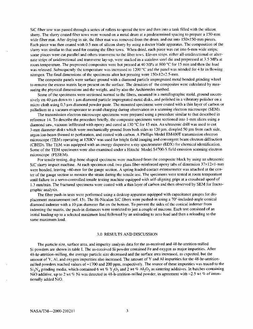
The particle size, surface area, and impurity analysis data for the as-received and 48-hr-attrition-milled
Si powders are shown in table I. The as-received Si powder contained Fe and oxygen as major impurities. After
48-hr-attrition-milling, the average particle size decreased and the surface area increased, as expected, but the
amount of Y, A1, and oxygen impurities also increased. The amount of Y and AI impurities for the 48-hr-attrition-
milled powders reached values of _-1700 and 200 ppm, respectively. The source of these impurities was traced to the
Si3N 4 grinding media, which contained 6 wt % Y203 and 2 wt % AI203 as sintering additives. In batches containingNiO additive, up to 2 wt % Ni was detected in 48-h-attrition-milled powder, in agreement with -2.5 wt % of inten-
tionally added NiO.
NASA/TM--2000-210211 3
3.1PhysicalProperties
Theroomtemperaturedensityandporosityofone-andtwo-dimensionalSiC/RBSNcompositesareshownintableII. Eachdatapointandcorrespondingstandarddeviationinthistablerepresentsanaverageofthreetestresults.The table indicates that the composites contain -23 vol % fibers and -37 vol % porosity.
3.2 Microstructure
To determine the degree of matrix infiltration between filaments in the fiber tows and processing defects, cross-
sections of one- and two-dimensional reinforced uncoated and three CVD coated Hi-Nicalon SiC/RBSN composites
were examined by optical microscopy. A typical cross-section of one-dimensional BN/SiC coated Hi-Nicalon SiC/
RBSN composite is shown in figure 1. This figure shows that the Si3N 4 matrix well infiltrated between filamentswithin the tows, but distinct matrix rich regions exist between the fiber tows. Also notice that the RBSN matrix con-
tains micron sized porosity with some isolated large pores throughout the cross-section. The SEM micrographs ofthe cross-sections of PBN and BN/SiC coated Hi-Nicalon/RBSN composites show that the CVD interface coatings
on Hi-Nicalon fibers are non-uniform and irregular (fig. 2). These two coatings represent coatings supplied by two
different vendors offering two different processing conditions. It is obvious in figure 2 that the thickness of the coat-
ing on the fibers decreases drastically from the periphery to the center of the tows, and in some cases the fibers at thecenter of the tows do not even contain the coating (fig. 2(a)). However, when the three coatings are compared, the
BN/SiC coating appears to be the most uniform. A higher magnification photograph of the cross-section of the com-
posites indicates that the uncoated and nonuniformly coated regions are prevalent where three or more fibers are
touching each other (fig. 3). Quantitative analysis was performed to determine the fraction of uncoated fibers in all
three coated composites. Results show that the number of uncoated filaments within the coated tows vary from tow
to tow and between the types of the coated fibers. In general, PBN, PBN/Si-PBN, and BN/SiC coated Hi-Nicalon
SiC/RBSN composites contained up to 30, 25, and 10 percent uncoated fibers,
respectively.
TEM analysis was performed to determine phase stability of the coating and possible reaction between the SiCfiber and RBSN matrix, or between the interface coating and RBSN matrix. In addition, the reaction between Nit
and uncoated SiC fibers, and between Nit and the interface coating(s) were also investigated. Results are shown in
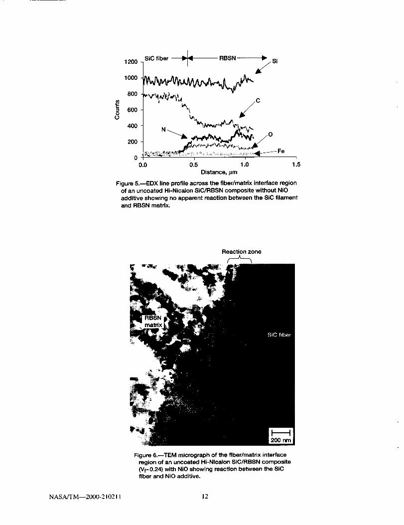
figures 4 and 5. A bright field TEM micrograph of the transverse cross-section, and EDX analysis across the fiber/matrix interface of the uncoated Hi-Nicalon SiC/RBSN composites without Nit show no evidence of a solid state
reaction between the Hi-Nicalon fiber and RBSN matrix (figs. 4 and 5). On the other hand, the uncoated Hi°Nicalon
SiC/RBSN composites containing Nit show chemical reaction wherever the Nit particles are in contact with the
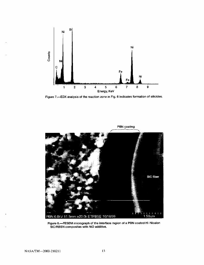
fibers (fig. 6). The average thickness of the reaction zone is ~0.1 _tm. EDX analysis indicates that the reaction zonecontains Fe and Ni (fig. 7). Characterization of the SAD pattern indicates that the reaction zone is composed of Fe
and Ni silicides (ref. 11). The presence of Fe can be traced to the silicon powder.
TEM examination of the interface zone of the composites indicates that except for the SiC coating all other
coatings consist of several layers (fig. 8). The PBN, Si-PBN and BN coatings are amorphous and the SiC coating is
crystalline and nodular. In some specimens, these layers were debonded. It is not clear whether debonding occurred
during specimen preparation or pre-existed. No chemical reaction was observed between the Hi-Nicalon SiC fibersand the PBN or the BN coating, or between the outer coating and RBSN matrix. However, wherever Nit came in
contact with the fiber coating, or the uncoated region of the fibers, chemical reaction was noticed. These observa-
tions are in agreement with the results reported in reference 11.
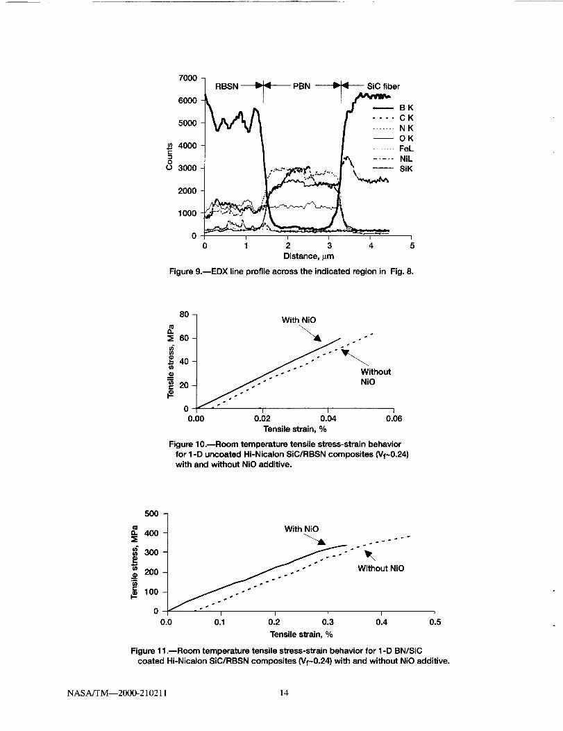
EDX analysis across the PBN, PBN/SiPBN, and BN/SiC coatings indicates small amounts of Si, O, and C
impurities in the BN or PBN coatings (fig. 9). Whether silicon in the BN coating is an artifact due to smearing dur-
ing polishing or silicon diffusing into the coating during processing is not known.
Based on TEM and SEM results we conclude that coatings of PBN, PBN/Si-rich PBN, and BN/SiC provided
adequate protection of the Hi-Nicalon SiC fibers from reaction with the Fe and Ni, but the CVD coating process
must be optimized to avoid uncoated regions on the fibers.
NASA/TM--2000-210211 4
3.3MECHANICALBEHAVIOR
3.3(a)InfluenceofNitridationEnhancingAdditive,NiO,onMechanicalBehavior
Transition metals and their oxides are generally used as nitridation enhancing additives in RBSN processing to
reduce the processing temperature and time. In monolithic RBSN these additives have no significant influence on
the strength. However, in SiC fiber reinforced RBSN composites, these additives react with bare fiber as well as
fiber coatings as reported earlier. To determine the influence of this reaction on tensile properties, uncoated and
BN/SiC coated Hi-Nicalon SiC fiber reinforced RBSN composites with and without NiO additives were tensile
tested at room temperature. The results are shown in figures 10 and 11. In these figures, the stress-strain curves are
displaced by 0.05 percent strain for better clarity. These figures indicate that the ultimate strength values of uncoated
and BN/SiC coated Hi-Nicalon SiC/RBSN composites containing NiO additives are slightly lower than those of
the composite fabricated without NiO. However, these strength values are well within the scatter band of strength
measured for these composites. Therefore, it appears that the nitridation-enhancing additive, NiO, hence NiO/SiC
reaction, may not have a significant effect on tensile properties of the composite.
3.3 (b) Influence of Interface Coating on Mechanical Behavior
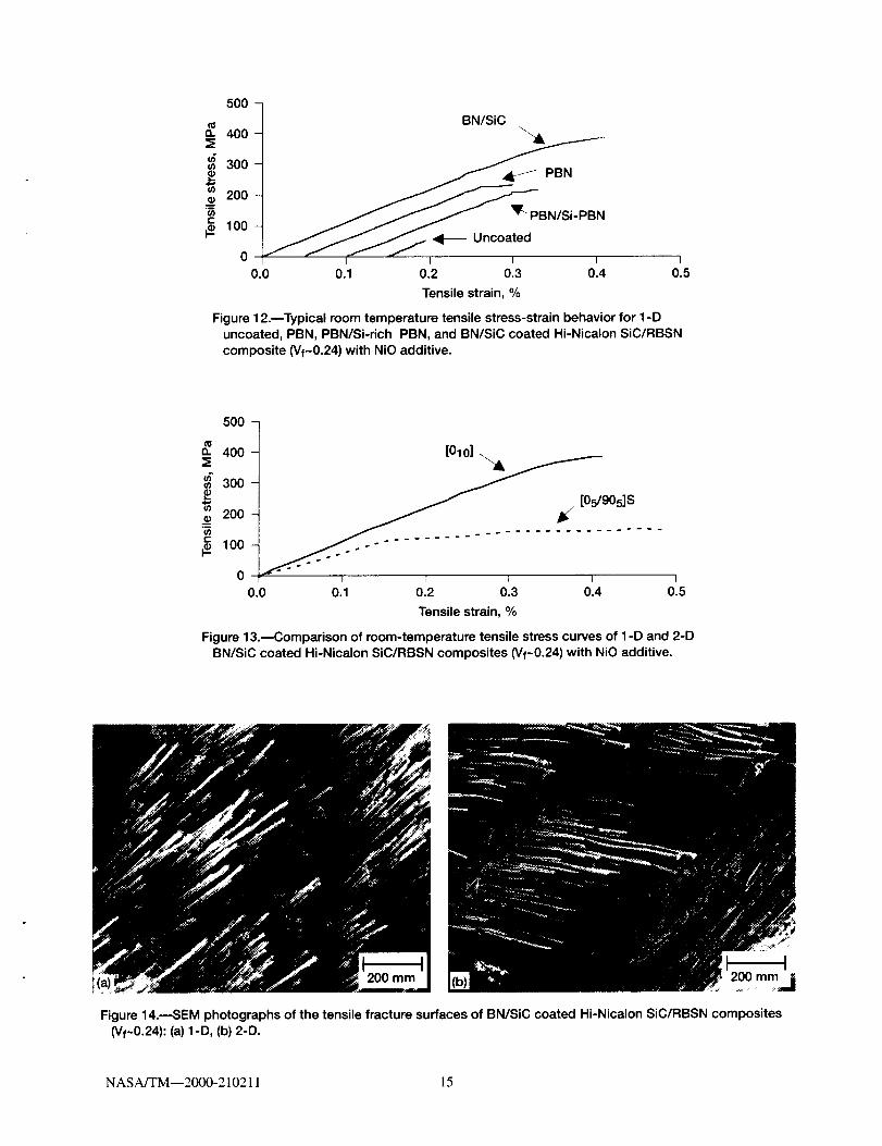
Room temperature tensile stress-strain behaviors of unidirectional reinforced uncoated, PBN, PBN/Si-PBN,
and BN/SiC coated (-24 vol%) Hi-Nicalon SiC/RBSN composites containing NiO additive are shown in figure 12.
In figure 12, the strain scale of PBN and PBN/Si-PBN coated, and uncoated Hi-Nicalon SiC/RBSN composites is
deliberately displaced by 0.05, 0.1, and 0.15 percent respectively, to distinguish the stress-strain behaviors. The
stress-strain curves of the uncoated Hi-Nicalon SiC/RBSN composites exhibited a linear elastic behavior until frac-
ture. This suggests that the matrix cracks do not deflect at the fiber matrix interface either because of a strong bond
formed between the fiber and the matrix under the processing conditions of the composites or because of the large
tensile residual stress acting upon the fiber. On the other hand, the stress-strain curve of the PBN, PBN/Si-PBN, and
BN/SiC coated Hi-Nicalon/RBSN composite shows an initial elastic region followed by a nonlinear region. The
nonlinear region for the PBN and PBN/Si-PBN coated Hi-Nicalon SiC/RBSN composites is much shorter than that
for the BN/SiC coated Hi-Nicalon/RBSN composite.
Typical room temperature tensile stress-strain behavior of [0] l0 and [05/905] s BN/SiC coated Hi-Nicalon SiC/RBSN composites (~24 vol %) is shown in figure 13. The stress-strain curves of the one- and two-dimensional rein-
forced BN/SiC coated Hi-Nicalon SiC/RBSN composites show two distinct regions: an initial linear region followed
by a non-linear region. At ultimate load the composite specimens failed abruptly. The tensile data for the one- and
two-dimensional RBSN composites reinforced by uncoated and three CVD coated Hi-Nicaion SiC fibers are tabu-lated in table III.
Figure 14 shows the fracture surfaces of one- and two-dimensional BN/SiC coated Hi-Nicalon SiC/RBSN com-
posites. In some regions of the fracture surface, flat fracture is noticed, while other regions exhibited significant
amount of fiber pullout, typical of a tough composite. In the flat fracture regions, the fibers appear to have no inter-
face coating. When the fractured specimen was viewed edge on, no multiple matrix cracks were observed. This
suggests that the matrix cracks are closed upon unloading the fractured specimen or that the fracture process is local-ized near the fracture surface.
3.4 INTERFACIAL SHEAR STRENGTH
The fiber push-in tests were performed at room temperature to measure interfacial shear strength properties of
each composite. The data were analyzed by subtracting the appropriate load-train compliance correction from the
measured displacements. The fiber debond initiation stress was determined and the frictional sliding stresses were
estimated. An estimate of frictional sliding stress, _, was made using the constant "t model of Marshall and Oliver(ref. 16) by fitting the following relationship to the reloading curves:
NASA/TM--2000-210211 5
u= uo+F2/8_2r3Efx
Whereuisthe fiber end displacement, uo is the residual fiber end displacement after the previous unloading, F
is the applied load, r is the fiber radius, and Ef is the fiber modulus. In addition, a debond initiation stress, Od, could
be calculated from the debond initiation load, Fa, (the load at which fiber end begins to move) by the relation, c d =Fd/_r2.
3.4 (a) Influence of Nitride Enhancing Additive, NiO, on Interfacial Shear
Many of the push-in tests of uncoated fibers could not be successfully completed due to the very, high fiber/
matrix bonding for uncoated fibers. For this reason, meaningful averages of debond initiation and frictional sliding
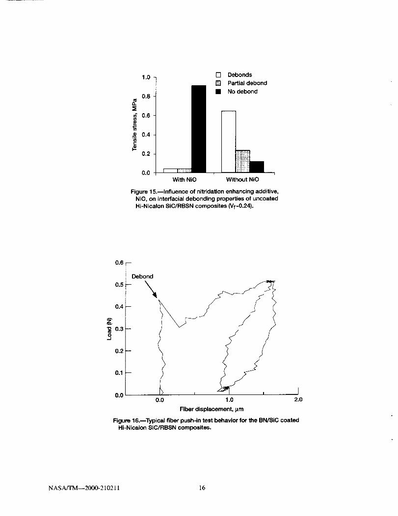
stresses could not be obtained. However, a significant effect of the presence of the NiO additive was still evident
from comparing the fraction of fibers that could be successfully debonded and pushed in for the uncoated SiC/RBSN
composites with and without the NiO additive (fig. 15). In the case of uncoated SiC/RBSN composites containing
no NiO, a large fraction of the fibers can be debonded, but these fibers are difficult to slide. On the other hand, in the
uncoated SiC/RBSN composites containing NiO, a large fraction of the fibers could not be debonded at all: signifi-
cant fiber damage occurred before debonding could be achieved. These differences in interfacial behavior can be
analyzed based on surface roughness of the fibers, and the chemical reaction between the fiber and the NiO additive.
Although there is no evidence of chemical reaction between uncoated SiC fiber and RBSN matrix without NiO
(figs. 4 and 5), roughening of the fiber surface can occur because of the Si3N 4 grains indenting on the fibers duringfabrication. As a result even though it is easier to debond the fiber, pushing the roughened fibers out of the RBSN
matrix during push-in test is difficult without damaging the fibers. In contrast, in the uncoated SiC/RBSN compos-
ites containing NiO, chemical reaction is seen in regions where the NiO additive in matrix encountered the fiber
(figs. 6 and 7). The strong bond formed between the SiC fiber and matrix results in high interfacial debond strength.
3.4 (b) Influence of Interface Coating on Interfacial Shear
The load-displacement curves generated from the push-in tests for the three-coated Hi-Nicalon SiC/RBSN com-
posites containing NiO additive are similar. A typical load-displacement curve for the one-dimensional BN/SiC
coated Hi-Nicalon SiC/RBSN composites with NiO additive is shown in figure 16. According to this figure, initially
the displacement increases with increase in load up to a critical load level at which the fiber debonded from the ma-
trix. Beyond this point the load momentarily decreased and then again increased with increasing displacement. The
interfacial property data for the composites with coated and uncoated fibers are summarized in table IV. Each data
point and the corresponding standard deviation in the table represent an average of 8 to 21 tests on coated fibers:
meaningful averages for the composite with uncoated fibers could not be obtained because the fiber/matrix bond
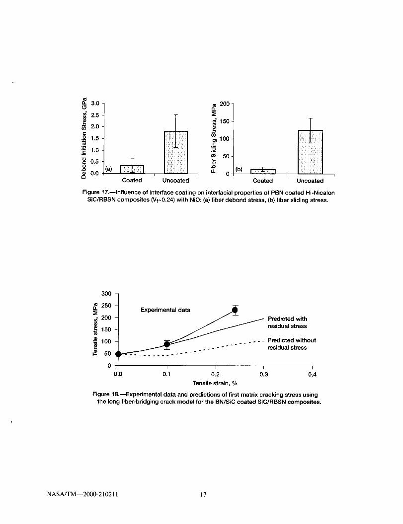
was too strong for most of the tests to achieve fiber/matrix debonding. As stated earlier, 10 to 30 vol % of the fibers
were found to contain uncoated regions in the coated composites. The interfacial frictional shear strength of the
poorly coated fibers reached values similar to those of uncoated composites (fig. 17). This shows that in order to
obtain reproducible interfacial shear properties, poorly coated and uncoated regions must be avoided.
3.5. MATRIX CRACKING STRENGTH PREDICTION
A fiber bridging crack model developed by Aveston, Cooper, and Kelly (ref. 17) was used to predict the matrix
cracking strength. The following expression for predicting the steady state matrix cracking strength (_ss) was used.
t_ss = [6XfFmVf2EfE 2 / RVmE_n] 1/3 (1)
Where F_,f,Em, and E C are the elastic moduli of the fiber, the matrix, and the composite (in the longitudinal direc-
tion), respectively, xf is the interfacial frictional shear strength, R is the fiber radius, F m is the matrix fracture energy,
NASA/TM--2000-210211 6
Vfisthefibervolumefraction,andV m is the matrix volume fraction. Accounting for the (longitudinal) thermalresidual stresses due to mismatch in the thermoelastic properties between the fiber and matrix in equation ( l ).
(Ycr = (3ss +G'R (21
and OR can be approximated by
(YR = ((Zf --O_ m)AT EfVf (3)
Where ctf and £tm are the linear thermal expansion coefficients of the fiber and the matrix, respectively, and ATis the temperature differential during processing. The variation of matrix cracking strength with fiber fraction was
predicted with and without accounting for thermal residual stresses using the values: Ef = 270 GPa, Em= 60 GPa, F m
= 36 J/m 2, t_f =3.8x10⁻⁶/°C, O_m = 5.4x10⁻⁶/°C, "r= 15 MPa, AT = 1175 °C and R = 7 lam. Predicted results and the
measured values are plotted in figure 18. The plot indicates that the predicted values for the matrix cracking strength
accounting for thermal residual stresses agree well with the measured values at low fiber fractions.
4.0 SUMMARY OF RESULTS
A processing method for small diameter SiC fiber reinforced RBSN composites has been developed, and the
effect of interfacial coating composition and nitridation enhancing additive on the properties of the composites have
been determined. Key findings are the following.
(1) Strong and tough small diameter Hi-Nicalon SiC fiber reinforced RBSN composites can be fabricated using
fiber lay-up method and a low temperature nitridation cycle.
(2) Significant variation in interface coating thickness and uncoated regions were noticed in PBN, PBN/
Si-PBN, and BN/SiC coated SiC/RBSN composites across the fiber tows.
(3) In the uncoated regions, the fiber surface is roughened and NiO additive reacted with the fibers to form
NiSi 2 and FeSi 2. Both these factors caused degradation of tensile strength in the SiC/RBSN composites.(4) All three-interface coatings namely the PBN, Si-PBN and BN/SiC are compatible with RBSN matrix. No
reaction was observed between these coatings and Hi-Nicalon SiC fibers or RBSN matrix.
(5) The first matrix cracking strength in SiC/RBSN composites can be conservatively predicted using a fiber
bridging crack model when residual stresses are taken into account.
5.0 CONCLUSIONS
Strong and tough SiC/RBSN composites can be fabricated using coated SiC tows. However, interface-coating
uniformity is a major issue affecting properties of the composites. Further improvements in composite properties are
possible by optimizing both the CVD coating process to achieve uniform interface coating thickness, and the fiber
lay up process to reduce matrix rich regions.
REFERENCES
1. R.T. Bhatt, "Effects of Fabrication Conditions on the Properties of SiC Fiber Reinforced Reaction-Bonded
Silicon Nitride Matrix Composites (SiC/RBSN)," NASA TM-88814 (1986).
2. O.J. Gregory and M.H. Richman, "Thermal Oxidation of Sputter-Coated Reaction-Bonded Silicon Nitride,"
J. Amer. Ceram. Soc. 67, #5, pp. 335-340 (1984).3. J. Desmaison, N. Rods, and P. Belair, "High-Temperature Oxidation-Protection CVD Coatings for Structural
Ceramics: Oxidation Behavior of CVD-Coated Reaction-Bonded Silicon Nitride," Mater. Sci. and Engin., A 121,
pp. 441--447 (1989).
4. W.R. Fohey, R.T. Bhatt, and G.Y. Baaklini, "Burner Rig and Engine Test Results of SiC/RBSN Composites,"
NASA-CP-19117, pp. 68, (1993).
NASA/TM--2000-210211 7
5. J.W.Lucek,G.A.Rossetti,Jr.,andS.D.Hartline,"StabilityofContinuousSi-C(-O)ReinforcingElementsinReaction-BondedSiliconNitrideProcessenvironments,"pp.27,inMetalMatrix,Carbon,andCeramicmatrixComposites1985,NASACP-2406,EditedbyJ.D.Buckley,NASA,Washington,D.C.,1985.6. T.L.Starr,D.L.Mohr,W.J.Lackey,andJ.A.Hanigofsky,"ContinuousFiber-ReinforcedReactionSintered
SiliconNitrideComposites,"Cer.Eng.Sci.Proc.,14[9-10]pp.1125-1132,(1993).7. G.H.WoblewskaandG.Ziegler,"Reaction-BondedSi3N4ReinforcedwithContinuousSiCFibers:Processing
andInterfaceCharacteristics,"in High-Temperature Ceramic-Matrix Composites II: Manufacturing and
Materials Development, Edited by A.G. Evans and R. Naslain, Ceramic Trans., 58, pp. 131-136 (1995).
8. M. Takeda, Y. Imai, H. Ichikawa, T. Ishikawa, N. Kasai, T. Seguchi, and K. Okamura, "Thermal Stability of the
Low Oxygen Silicon Carbide Fibers Derived from Polycarbosilane," Ceram. Eng. Sci. Proc., 13 (7-8), pp. 209-217
(1992).9. J.B. Hurst, D. Gorican, and H.M. Yun, "A Comparison of the Mechanical Properties of Three Polymer Derived
Small Diameter SiC Fibers," in Advances in Ceramic Matrix Composites III Edited by N.P. Bansal and J.P. Singh,
Ceramic Trans. 58, pp. 131-136 (1995).10. R.T. Bhatt and A. Garg, "Strength and Microstructural Stability of Hi-Nicalon SiC Fibers in N 2 and in Nitrida-
tion Environment," Proc. ICCM 10, Eds. A. Poursartip, and K. L Street, VI, pp. 339-347 (1995).
11. R.T. Bhatt and D.R. Hull, "Effects of Fiber Coatings on Tensile Properties of Hi-Nicalon SiC/RBSN Tow Com-
posites," NASA TM-113170.12. R.T. Bhatt and A.R. Palczer, "Effects of Surface Area, Polymer Char, Oxidation, and NiO Additive on Nitrida-
tion Kinetics of Silicon Powder Compacts," J. Mat. Sci., 34, pp. 1483-1492 (1999).
13. T.P. Herbell, T.K. Glasgow and N.W. Orth, "Demonstration of a Silicon Nitride Mill for Production of Fine
Pure Si and Si3N 4 Powders," Bull. Amer. Ceram. Soc. 63 [9], pp. 1176, (1984).14. R. Koch and A.F. Marshall, "Specimen Preparation for Transmission Electron Microscopy of Materials II,"
Mater. Res. Soc. Symp. Proc., 199, pp. 145-152 (1990).15. J.I. Eldridge, "Desktop Fiber Push-Out Apparatus," NASA TM-105341 (1991).16. D.B. Marshall and W.C. Oliver, "An Indentation Method for Measuring Residual Stresses in Fiber-Reinforced
Ceramics," Mater. Sci. Eng. A, 126, pp. 95-103 (1990).17. J. Aveston, G. Cooper, and A. Kelly, Single and Multiple Fracture, in: The Properties of Fiber Composites
(Conference Proceedings, National Physical Laboratory, Guildford) IPC Science and Technology Press Ltd., 1971.
NASA/TM--2000-210211 8
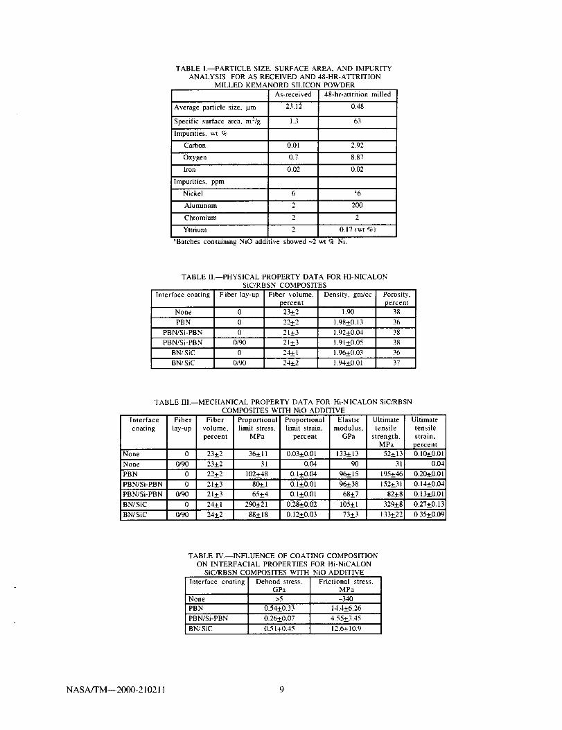
TABLE I.--PARTICLE SIZE, SURFACE AREA, AND IMPURITYANALYSIS FOR AS RECEIVED AND 48-HR-ATTRITION
MILLED KEMANORD SILICON POWDER
As-received 48-hr-attrition milled
Average particle size, _tm 23.12 0.48
Specific surface area, m2/g 1.3 63
Impurities. wt %
Carbon 0.01 2.92
Oxygen 0.7 8.87
Iron 0.02 0.02
Impurities, ppm
Nickel 6 _6
Aluminum 2 200
Chromium 2 2
Yttrium 2 0.17 _wt %
aBatches containing NiO additive showed -2 "art % Ni.
TABLE II.--PHYSICAL PROPERTY DATA FOR HI-NICALON
SiC/RBSN COMPOSITES
Interface coating
None
Fiber lay-up Fiber volume,
percent23±2
Density. gnffcc
1.90
Porosity,
percent38
PB N 0 22±2 1.98±0.13 36
PBN/Si-PBN 0 21±3 1.92+_0.04 38
PBN/Si-PBN 0/90 21 +_3 1.91 ±0.05 38
BN/SiC 0 24+_1 1.96+_0.03 36
BN/SiC 0/90 2'4+_2 1.94+_0.01 37
TABLE III.--MECHANICAL PROPERTY DATA FOR Hi-NICALON SiC/RBSN
COMPOSITES WITH NiO ADDITIVE
Interface Fiber Fiber
coating lay-up volume,
percent
None 0 23+2
None 0/90 23+2
PBN 0 22+_2
PBN/Si-PBN 0 21±3
PBN/Si-PBN 0/90 21+_3
BN/SiC 0 24±1
BN/SiC 0/90 24+_2
Proportional Proportionallimit stress, limit strain,
MPa percent
36+11 0.03+0.01
31 0.04
102+_48 0.1+0.04
80+_1 0.1+0.01
65+4 0.1+0.01
290+21 0.28+0.02
88+18 0.12+0.03
Elastic Ultimate
modulus, tensile
GPa strength,MPa
133+_13 52+_13
90 31
96+_ 15 195+46
96+_38 152+31
68+7 82+8
105+1 329±8
73+_3 133+22
Ultimate
tensile
strain,
percent0.10+0.01
0.04
0.20+_0.01
O. 14+_0.04
0.13+0.01
0.27±0.13
0.35+-0.09
TABLE IV.--INFLUENCE OF COATING COMPOSITION
ON INTERFACIAL PROPERTIES FOR Hi-NiCALON
SiC/RBSN COMPOSITES WITH NiO ADDITIVE
Interface coating Debond stress, Frictional stress,GPa MPa
None >5 ~340
PBN 0.54+_0.33 14.4+_6.26
PBN/Si-PBN 0.26±0.07 4.55+-3.45
BN/SiC 0.5 l±0.45 12.6+_10.9
NASA/TM--2000-21021 1 9
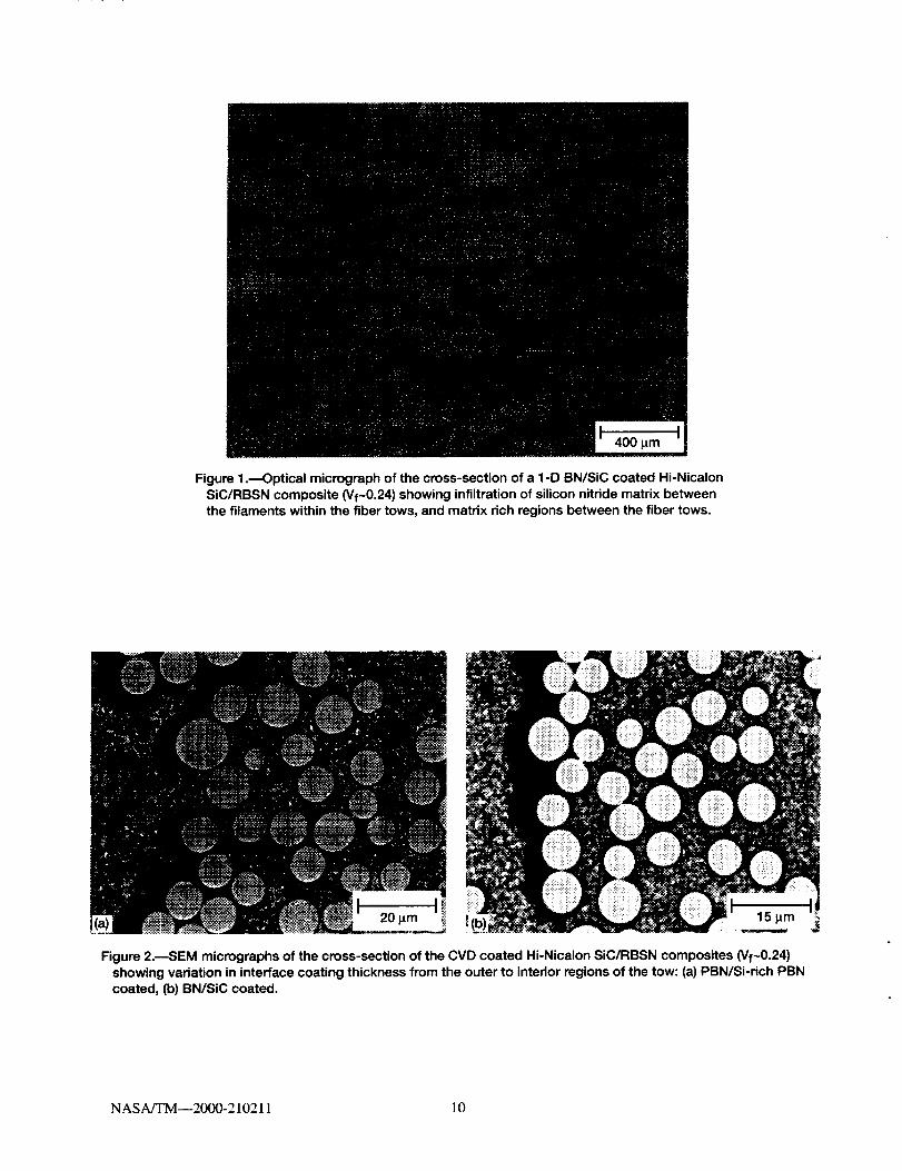
Figure 1 .--Optical micrograph of the cross-section of a 1-D BN/SiC coated Hi-Nicalon
SiC/RBSN composite (Vf-0.24) showing infiltration of silicon nitride matrix betweenthe filaments within the fiber tows, and matrix rich regions between the fiber tows.
20.m I!i_! 15 t_m
Figure 2.--SEM micrographs of the cross-section of the CVD coated Hi-Nicalon SiC/RBSN composites (Vf-0.24)
showing variation in interface coating thickness from the outer to intedor regions of the tow: (a) PBN/Si-rich PBN
coated, (b) BN/SiC coated.
I
NASA/TM--2000-210211 10
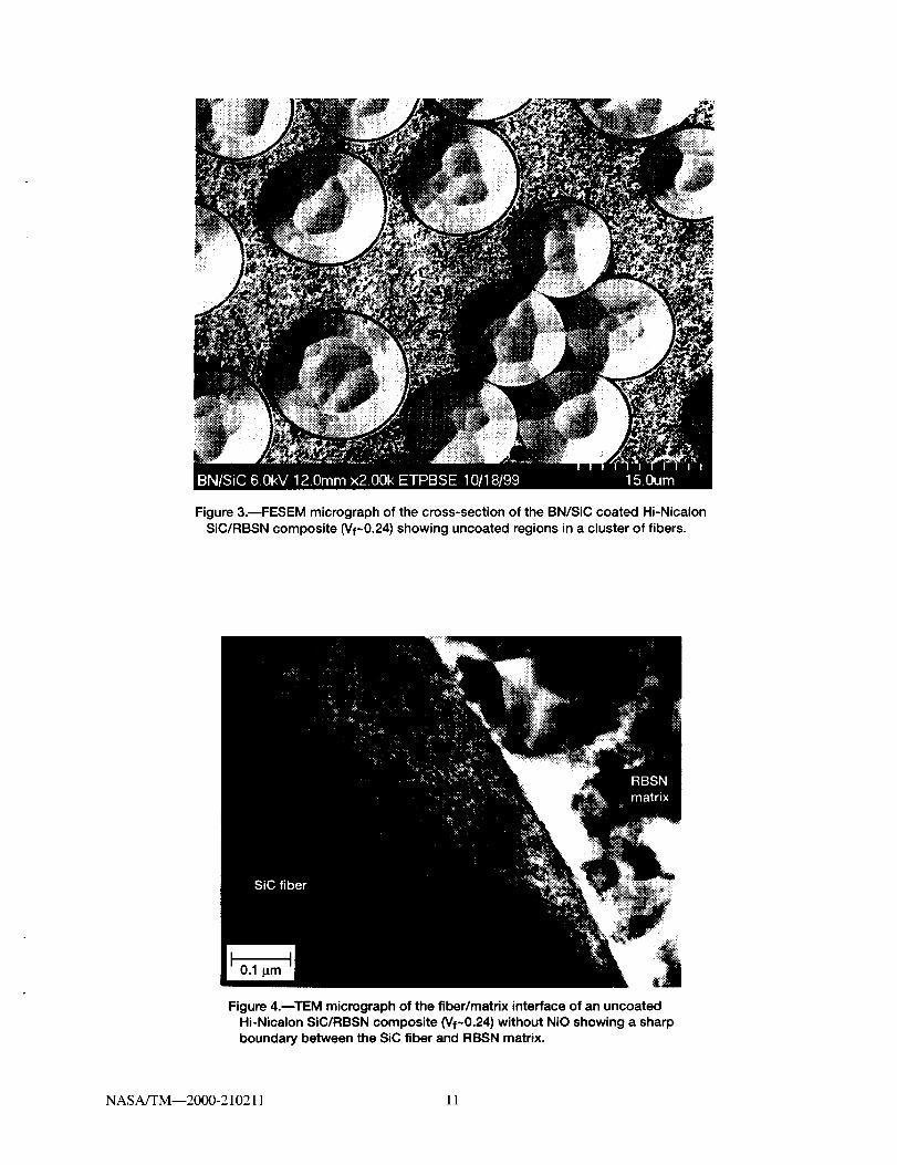
Figure 3.--FESEM micrograph of the cross-section of the BN/SiC coated Hi-Nicalon
SiC/RBSN composite (Vf~0.24) showing uncoated regions in a cluster of fibers.
Figure 4.BTEM micrograph of the fiber/matrix interface of an uncoated
Hi-Nicalon SiC/RBSN composite (Vf~0.24) without NiO showing a sharp
boundary between the SiC fiber and RBSN matrix.
NASA/TM--2000-210211 11
C
0(3
1200 SiC fiber ,=1_, RBSN .__1TM Si
800_r_.,_j'._,,_ c600 I,%\ /
4oo4 N '_'_""_'" '-' _ "=_'_ o
0 '_:_:_:_-_:_'__ ...............................i........................................'_:_:_ ...........i......"0.0 0.5 1.0 1.5
Distance, I_m
Figure 5.--EDX line profile across the fiber/matrix interface regionof an uncoated Hi-Nicalon SiC/RBSN composite without NiO
additive showing no apparent reaction between the SiC filamentand RBSN matrix.
Reaction zone
Figure 6.toTEM micrograph of the fiber/matrix interface
region of an uncoated Hi-Nicalon SiC/RBSN composite(Vf~0.24) with NiO showing reaction between the SiCfiber and NiO additive.
NASA/TM--2000-210211 12
r",._O
O
NiSi
Fe
Ni
Ni
1 2 3 4 5 6 7 8 9
Energy, KeY
Figure 7.mEDX analysis of the reaction zone in Fig. 6 indicates formation of silicides.
PBN coating
Figure 8.mFESEM micrograph of the interface region of a PBN coated Hi-NicalonSiC/RBSN composites with NiO additive.
NASA/TM--2000-210211 13
7000
6000
5000
4000E
0o 3000
2000
1000
0
RBSN _ PBN _ SiC fiber
• FeL
_'_ ..... NiL
I I I I I
0 1 2 3 4 5
Distance, Hm
Figure 9.--EDX line profile across the indicated region in Fig. 8.
8O
O.
60
_ 40
I1)
_ 2o
With NiO
0 i I i i0.00 0.02 0.04 0.06
Tensile strain, %
Figure 10.--Room temperature tensile stress-strain behaviorfor 1-D uncoated Hi-Nicaion SiC/RBSN composites (Vf~0.24)with and without NiO additive.
5OO
400
300
¢ 200
lO0
0
With NiO
Without NiO
I I I I t
0.0 0.1 0.2 0.3 0.4 0.5
Tensile strain, %
Figure 11 .--Room temperature tensile stress-strain behavior for 1-D BN/SiC
coated Hi-Nicalon SiC/RBSN composites (Vf~0.24) with and without NiO additive.
NASA/TM--2000-210211 14
500 -
_; 400-
300==
¢_ 200
IO" 100
BN/SiC
BN/Si-PBN
o coate 0 I I i I I
0.0 0.1 0.2 0.3 0.4 0.5
Tensile strain, %
Figure 12.nTypical room temperature tensile stress-strain behavior for 1-Duncoated, PBN, PBN/Si-rich PBN, and BN/SiC coated Hi-Nicalon SiC/RBSN
composite (Vf~0.24) with NiO additive.
_; 400-
300
• 200
_. loo
I I I I I
0.0 0.1 0.2 0.3 0.4 0.5
Tensile strain, %
Figure 13.nComparison of room-temperature tensile stress curves of 1-D and 2-DBN/SiC coated Hi-Nicalon SiC/RBSN composites (Vf~0.24) with NiO additive.
Figure 14.---SEM photographs of the tensile fracture surfaces of BN/SiC coated Hi-Nicalon SiC/RBSN composites(Vf~0.24): (a) 1-D, (b) 2-D.
NASA/TM--2000-210211 15
O.
u}
_¢
e=
1.0
0.8
0.6
0.4
0.2
0.0With NiO
[] Debonds
[] Partialdebond
• No debond
Figure 15.--Influence of nitridation enhancing additive,NiO, on interfacial debonding properties of uncoatedHi-Nicalon SiC/RBSN composites (Vf~0.24).
z
O.J
0.6 m
0.5
0.4
0.3
0.2
0.1
Debond
-\
0.0 i = I0.0 1.0 2.0
Fiber displacement, I_m
Figure 16.--Typical fiber push-in test behavior for the BN/SiC coatedHi-Nicalon SiC/RBSN composites.
NASA/TM--2000-210211 16
con 3.0L9
2.5
_ 2.0¢-
o 1;5co
,D
'_ 1.0
"_ 0.5o
0.0a
co 200a.
_ 150
m 100t--
"o
_ 50
ir 0Coated Uncoated Coated Uncoated
Figure 17.Dlnfluence of interface coating on interfacial properties of PBN coated Hi-Nicalon
SiC/RBSN composites (Vf~0.24) with NiO: (a) fiber debond stress, (b) fiber sliding stress.
300 -
co 250 -
__a. Experimental data
d 200 - Predicted witho_ residual stress=¢ 150 -
0_= 100 - Predicted without_" residual stress
50(
0 I I E I0.0 0.1 0.2 0.3 0.4
Tensile strain, %
Figure 18.DExperimental data and predictions of first matrix cracking stress usingthe long fiber-bridging crack model for the BN/SiC coated SiC/RBSN composites.
NASA/TM--2000-210211 17
Form ApprovedREPORT DOCUMENTATION PAGE
OMB No. 0704-0188
Public reporting burden for this collection of information is estimated to average 1 hour per response, including the time for reviewing instructions, searching existing data sources,gathering and maintaining the data needed, and compleling and reviewing the collection of information. Send comments regarding this burden estimate or any other aspect ol thiscollection of intormation, including suggestions for reducing this burden, to Washington Headquarters Services, Direclorate for Information Operations and Reports, 1215 JeffersonDavis Highway, Suite 1204, Arlington, VA 22202-4302, and to the Office of Management and Budget, Paperwork Reduction Project (0704-0188), Washington, DC 20503.
1. AGENCY USE ONLY (Leave blank) 2. REPORT DATE 3. REPORT TYPE AND DATES COVERED
September 2000 Technical Memorandum
4. TITLE AND SUBTITLE 5. FUNDING NUMBERS
Effects of Interface Coating and Nitride Enhancing Additive on Properties of
Hi-Nicalon SiC Fiber Reinforced Reaction-Bonded Silicon Nitride Composites
6. AUTHOR(S)
Ramakrishna T. Bhatt, David R. Hull, Jeffrey I. Eldridge, and Raymond Babuder
7. PERFORMING ORGANIZATION NAME(S) AND ADDRESS(ES)
National Aeronautics and Space Administration
John H. Glenn Research Center at Lewis Field
Cleveland, Ohio 44135-3191
i 9. SPONSORING/MONITORING AGENCY NAME(S) AND ADDRESS(ES)
National Aeronautics and Space Administration
Washington, DC 20546-0001
WU-523-31-13-00
8. PERFORMING ORGANIZATION
REPORT NUMBER
E-12330
10. SPONSORING/MONITORING
AGENCY REPORT NUMBER
NASA TM--2000-210211
11. SUPPLEMENTARY NOTES
Ramakrishna T. Bhatt, U.S. Army Research Laboratory, NASA Glenn Research Center, Cleveland, Ohio; David R. Hull
and Jeffrey I. Eldridge, NASA Glenn Research Center: Raymond Babuder, Case Western Reserve University, Cleveland,
Ohio 44106. Responsible person, Ramakrishna T. Bhatt, organization code 5130, (216) 433-5513.
12a. DISTRIBUTION/AVAILABILITY STATEMENT
Unclassified- Unlimited
Subject Category: 24 Distribution: Standard
This publication is available from the NASA Center for AeroSpace Information. (301) 621-0390.
12b. DISTRIBUTION CODE
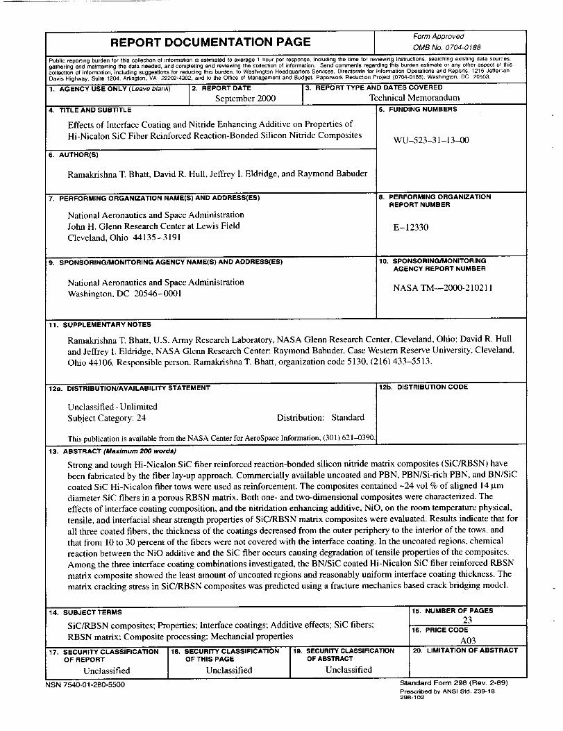
13. ABSTRACT (Maximum 200 words)
Strong and tough Hi-Nicalon SiC fiber reinforced reaction-bonded silicon nitride matrix composites (SiC/RBSN) have
been fabricated by the fiber lay-up approach. Commercially available uncoated and PBN, PBN/Si-rich PBN, and BN/SiC
coated SiC Hi-Nicalon fiber tows were used as reinforcement. The composites contained -24 vol % of aligned 14 _tm
diameter SiC fibers in a porous RBSN matrix. Both one- and two-dimensional composites were characterized. The
effects of interface coating composition, and the nitridation enhancing additive, NiO, on the room temperature physical,
tensile, and interfacial shear strength properties of SiC/RBSN matrix composites were evaluated. Results indicate that for
all three coated fibers, the thickness of the coatings decreased from the outer periphery to the interior of the tows, and
that from l0 to 30 percent of the fibers were not covered with the interface coating. In the uncoated regions, chemical
reaction between the NiO additive and the SiC fiber occurs causing degradation of tensile properties of the composites.
Among the three interface coating combinations investigated, the BN/SiC coated Hi-Nicalon SiC fiber reinforced RBSN
matrix composite showed the least amount of uncoated regions and reasonably uniform interface coating thickness. The
matrix cracking stress in SiC/RBSN composites was predicted using a fracture mechanics based crack bridging model.
14. SUBJECT TERMS
SiC/RBSN composites; Properties; Interface coatings; Additive effects; SiC fibers;
RBSN matrix: Composite processing; Mechancial properties
, 17. SECURITY CLASSIFICATION 18. SECURITY CLASSIFICATION 19. SECURITY CLASSIRCATION
OF REPORT OF THIS PAGE OF ABSTRACT
Unclassified Unclassified Unclassified
NSN 7540-01-280-5500
15. NUMBER OFPAGES
2316. PRICE CODE
A03
20. LIMITATION OF ABSTRACT
Standard Form 298 (Rev. 2-89)
Prescribed by ANSI Stcl. Z39-18298-102