effects of surface polishing the · pdf fileeffects of surface polishing ... a sketch of the...
TRANSCRIPT

The r i n c i p
EFFECTS OF SURFACE POLISHING ON THE MICROSTRAIN BEHAVIOR
OF TELESCOPE MIRROR MATERIALS
By W i l l i a m A. Eul & W. W i l l i a m Woods The Boeing Company*
SUMMARY
1 obj t ive of t h i s program has been t o determine t h e ex ten t of removal by po l i sh ing techniques of t h e s u r f a c e damage engendered by m i l l i n g o r grinding of candida te mir ror s u b s t r a t e materials. This o b j e c t i v e has been f u l f i l l e d wi th t h e p re sen ta t ion of q u a n t i t a t i v e f i g u r e s of m e r i t obtained when var ious su r face t rea tments are employed.
Materials t e s t e d inc lude fused s i l i ca (Corning 7 9 4 0 ) , t i t an ium doped s i l ica (Corning 7 9 7 1 ) , CER-VIT 101 (Owens-Illinois), and p o l y c r y s t a l l i n e s i l i c o n (Exotic Mate r i a l s ) .
Specimens were t e s t e d i n t o r s i o n a l shea r i n f o u r states of s u r f a c e prepara t ion : mi l led o r coarse ground, etched, lapped o r f i n e ground, and polished. Two schedules of lapping o r f i n e gr inding were inves t iga t ed ;
p i t s produced by t h e previous ab ras ive , and "controlled" lapping i n which t h e s u r f a c e material is removed t o a depth equal t o t h r e e t i m e s t h e average diameter of t h e previous abras ive . Specimens subjec ted t o t h e con t ro l l ed lapping sequence e x h i b i t s i g n i f i c a n t l y lower su r face damage e f f e c t s than those i n t h e conventionally lapped condi t ion . F i n a l po l i sh ing of specimens a f t e r f i n e grinding reduces t h e su r face y i e l d s t i l l f u r t h e r , t o w i th in t h e uncer- t a i n t y band presented by measuring and d a t a reduct ion system p rec i s ion l i m i t s .
conventional" lapping i n which material is removed only t o t h e base of t h e I I
INTRODUCTION
S tudies of proposed o r b i t a l astronomical t e l e scopes have ind ica t ed t h e need f o r d i f f r a c t i o n l imi t ed o p t i c s i n order t o d e r i v e t h e maximum b e n e f i t from operating i n t h e space environment. performance of l a r g e space t e l e scope mi r ro r s , t h e s t r a i n s t a b i l i t y of t h e s u b s t r a t e material must be optimized, Mirror s u b s t r a t e s are i n i t i a l l y shaped by m i l l i n g o r rough grinding opera t ions . on fused s i l i ca and d e v i t r i f i e d g l a s s i n t o r s i o n ( re ferences 1 and 2) have
To i n s u r e d i f f r a c t i o n l imi t ed
Previous mic ros t r a in tests
* Research and Engineering Division, S e a t t l e , Washington
https://ntrs.nasa.gov/search.jsp?R=19730008920 2018-05-08T14:21:33+00:00Z

ABSTRACT
Rough ground s i l i c i c mir ror s u b s t r a t e materials have been found i n previous inves t iga t ions t o e x h i b i t s i g n i f i c a n t s u r f a c e y i e l d . by su r face e tch ing , a procedure not normally employed i n t h e f i n i s h i n g of o p t i c a l t e lescope mir rors . The present work i n v e s t i g a t e s e f f e c t s of f i n e grinding and pol i sh ing techniques as w e l l as graded etching. measurements of y i e l d s t r a i n versus stress are made on fou r can s u b s t r a t e materials: p o l y c r y s t a l l i n e s i l i c o n , ULE si l ica 7971, and fused s i l i c a 7940. Commonly employed f i n e gr inding and pol are shown t o remove a major po r t ion of t h e su r face y i e l d found i n rough ground mir ror s u b s t r a t e materials.
This e f f e c t w a s removed
Tors iona l shear

i nd ica t ed t h a t su r f ace damage from rough gr inding imparts a permanent y i e l d c h a r a c t e r i s t i c t o t h e sur face . Removal of a few t e n t h s of a m i l l i m e t e r of su r f ace by ac id e t c h removes t h e y i e l d c h a r a c t e r i s t i c , l eav ing t h e base material without apprec iab le permanent deformation a t a l l loads up t o f r a c t u r e .
The por t ions of a t e l e scope mir ror not a c t i v e l y employed f o r o p t i c a l r e f l e c t i o n are o f t e n ac id etched su r face roughness is unsui t h e active r e f l e c t i n g s prepared by mechanical l a p t h f i n e gr inding The su r face y i e l d c h a r a c t e r i s t i c produced by t h i s determined, and ques t ions have been r a i s e d as t o t h e s u i t a b i l i t y of p re sen t ly employed f i n e gr inding and pol i sh ing procedures.
remove su r face damage.
The f i r s t o b j e c t i v e of t h e present program w a s t o determine t h e depth of su r face damage from coarse grinding. By t e s t i n g specimens a f t e r success ive etches of t h e order of 0.01 mm removal each, t h e gradual improvement of c h a r a c t e r i s t i c s from t h e rough gr ind t o t h e f u l l y e tched base material w a s expected t o be revea led , and t h e e f f e c t i v e depth of damage determined.
The second, and major ob jec t ive of t h i s program w a s t o determine t h e ex ten t of su r f ace damage removable by graded lapping o r f i n e gr inding techniques and t h e establishment of a f i n e gr inding and po l i sh ing schedule o r r ec ipe t o achieve an optimum sur face . T e s t s of "conventionally" lapped specimens, where material i s removed only t o t h e base of previous p i t s , are compared with specimens lapped t o g r e a t e r depths.
The t h i r d ob jec t ive is t h e determinat ion of mic ros t r a in behavior of poly- c r y s t a l l i n e s i l i c o n mir ror s u b s t r a t e material, i n t h e ground, e tched , and polished condi t ions .
EXPERIMENTAL APPARATUS
The experimental apparatus used i n t h i s program is t h e t o r s i o n test equipment described i n r e fe rence 2, with minor c i r c u i t r y modif icat ions t o s impl i fy opera t ion . The b a s i c loading and readout systems are unchanged. A manually operated hydraul ic pump opera tes a hydraul ic cy l inde r which loads t h e specimen through a strain-gaged lever arm. t o determine load level. Load release is e f f e c t e d by va lv ing a pressur ized accumulator under t h e automatic c o n t r o l of d e f l e c t i o n l i m i t switches, When load is r e l eased , t h e designed-in backlash of t h e loading system completely uncouples t h e loading t r a i n from t h e specimen and t h e specimen is f r e e t o r e l a x without f r i c t i o n o r load t r a i n inf luence . A ske tch of t h e t o r s i o n mic ros t r a in apparatus is shown i n f i g u r e 1. A concent r ic double walled thermal enclosure with two-zone thermal c o n t r o l system maintains t h e t e s t i n g appara tus a t a near-constant temperature of 306K.
The s t r a i n gages are monitored
2

T SWITCH PLATE
-LOAaING ARM, IN NEUTRAL POSlTION HYDRAULIC LI
HYDRAULIC ACTUATOR-
.f-
VIEW A-A
d FRAME ASSEMBLY
I
A l+l I 1
3

The extensometer, i n t h e form of instrumented lava cups, is cemented t o
Linear v a r i a b l e d i f f e r e n t i a l t ransformers , low stress shoulders on t h e specimen between t h e end loading s e c t i o n s and t h e test s e c t i o n (see f i g u r e 2). mounted around t h e periphery of t h e cups, are summed t o read out d i f f e r e n t i a l angular motion and t o d i sc r imina te aga ins t d i f f e r e n t i a l l i n e a r o r bending motions. Provis ions are made t o monitor bending
Readout of specimen loading and d e f l e c t i o n voltmeter and p r i n t e r , t r i g g e r s t h e vol tmeter -pr in te r t o l o g of 5, 50, 500, and 5000 seconds u n t i l quasi- logari thmic t i m e scale is chosen t o f a c i l i t a t e d a t a reduction. The sequencer resets automat ica l ly at t h e end of a present i n t e r v a l , and a c t i v a t e s an alarm t o alert t h e opera tor t o i n i t i a t e t h e succeeding loading sequence.
Upon release o
1
TEST SPECIMENS
T e s t specimens, as shown i n f i g u r e 3, have a convent ional c y l i n d r i c a l tes t s e c t i o n terminated by low-stress shoulders t o which t h e extensometer is cemented. Threaded, l a r g e c ross -sec t ion ends allow secure f a s t en ing t o cemented-on load g r ips .
Materials chosen f o r t h e test were as follows:
Material No. of Blanks Specimen Numbers
P o l y c r y s t a l l i n e S i l i c o n Mirror Blank Grade
7971 ULE Fused S i l i c a Mirror Blank Qual i ty
4 201-204
CER-VIT C-101 6 Premium Grade Mirror Blank Quality
6 211-2 16
221-226
7940 Fused S i l i ca Mirror Blank Quality
6 231-236
Specimen Prep ar a t i o n
T e s t specimens were machined from each material upon r e c e i p t from t h e supp l i e r wi th a 120-grit diamond wheel. subjec ted t o a hea t treatment of 810 K f o r one hour wi th oven cooling. Although t h i s treatment cannot be considered an anneal ing treatment f o r t h e base material, i t has been found adequate t o s t a b i l i z e su r face stresses. An attempt w a s made t o provide an annealing treatment i n vacuum t o t h e f i r s t two s i l i c o n specimens, bu t i n t h e process a e u t e c t i c w a s formed wi th t h e
P r i o r t o t e s t i n g , specimens were
4

- UPPER ZlUT
UPPEK LAVA CUP
1,OIJER LAVA CUI’
I
Fi’re 2: SPECIMEtV - EX TER A LY 5

r 7 / 8 -20 UNEF-2A
.125 f.003 TYP
(7.111.021
- CHAMFER .77+_.01 D I A (19.6+. 2 1
1 . 1 0 0 ~ . 0 0 1 DIA, TYP L' (27.94k.02)
.OS+_.Ol R. TYP (1.3% 2)
(12 .7f . 1) - .500~.005 D I A TYP
ALL DIMENSIONS I N INCHES (mm)
PART TO BE STRESS RELIEVED BEFORE AND AFTER MACHINING.
. BREAK ALL CORNERS .005 to .010 R ( . l to . 2 ) ALL DIAMETERS TO BE CONCENTRIC,WITH
END CENTERS WITHIN -001 T I R . (.02)
Figure 3: TEST SPECIMEN SKETCH
6

steel holding f i x t u r e and t h e specimens w e r e destroyed. s u r f a c e s t a b i l i z a t i o n hea t treatment was employed.
The rea f t e r only t h e
Surface Treatment
Af t e r an i n i t i a l test i n rough ground condi t ion subjec ted t o an a c i d etch. E t formulations p e c u l i a r l i s t e d i n Appendix A. Tests of specimens etched t o mo depths showed a d r a s t i c ovement over t h e rough g sequent e tch ing produced y l i t t l e change, and no at grada t ion of e tch.
The b a s i c i n t e n t of t h i s work was t o eva lua te convent ional and c u r r e n t p r a c t i c e s of mi r ro r s u r f a c e prepara t ion . chosen f o r eva lua t ion , adapted from t h e work of r e fe rence 3 wherein s u r f a c e t e n s i l e s t r e n g t h of p lane s i r r o r s w a s r e l a t e d t o removal of su r f ace micro- cracks. The "conventional" f i n e grind procedure employed i n t h e pas t employed each abras ive only t o t h e poin t of removal of p i t s f r o m t h e previous abras ive . The above r e fe rence calls out a schedule of su r face removal f o r each abras ive corresponding t o 60% of t h e average diameter of t h e previous abras ive . con t ro l l ed f i n e grind schedule on t h e o the r hand, calls f o r removal of t h r e e times t h e diameter of t h e previous abras ive . I n t h i s program, t h e choice of abras ive material type w a s unimportant t o t h e test r e s u l t s , and w a s l a r g e l y determined by shop personnel preference f o r optimum c u t t i n g rates. Grindin and pol i sh ing schedules followed i n t h i s program are l i s t e d i n Appendix A.
Two f i n e gr ind procedures were
The
Prepara t ion , t e s t i n g and s u r f a c e treatment h i s t o r i e s of each specimen me l i s t e d i n Appendix B.
TEST PROGRAM
A t t h e start of t h i s program, a series of 32 tests was scheduled t o determine t h e t o r s i o n microyield p rope r t i e s of s i l i c o n , fused si l ica, and d e v i t r i f i e d g l a s s mir ror s u b s t r a t e s . Surface conditions t o be inves t iga t e4 included coarse ground (mi l led) , etched, f i n e ground (lapped), and pol i shed , This schedule has been followed as c lose ly as poss ib l e , although problems with specimen breakage and f a b r i c a t i o n procedures have caused a few devia t ions . Appendix B lists t h e h i s t o r i e s of test specimens.
T e s t Procedures
The specimen under test is cemented t o t h e extensometer cups wi th a thermoplastic cement, Phenoxy 880, which has a working temperature of 440 K, Threaded loading g r i p s are a t tached t o t h e threaded ends of t h e specimen wi th a s i l i ca t e - loaded wax which has a working temperature of 370 K. With
7

t h i s combination, secure , s t r a i n - f r e e attachment i s made i n success ive opera t ions without mutual i n t e r f e rence .
Af te r i n s t a l l a t i o n i n t h e t o r s i o n test apparatus , the specimen and extensometer are g iven a minimum of 24 hours t o come t o thermal equilibrium. Temperature i n t h e inner test chamber i s con t ro l l ed t o 306K wi th a s t a b i l i t y of - +.005 K.
Specimen loading is accomplished i n logari thmic i t h e f i f t h r o o t of t en , from 0.7 t o 30 meganewtons increments are made i n a l t e r n a t e d i r e c t i o n s t o zero re ference . Load i s appl ied by opera t ion of a hydraul ic cy l inder with a hand pump. When t h e des i r ed load i s reached, t h e load and extensometer readings are recorded. The load is r e l eased over a per iod of two seconds o r less by va lv ing a pressur ized accumulator t o r e t u r n t h e hydraul ic cy l inder t o zero pos i t i on , where a l i m i t switch s tops t h e r e t u r n motion automatical ly . D i g i t a l vol tmeter recordings of t h e extensometer output are programmed by a n e l e c t r o n i c t i m e r a t prescr ibed i n t e r v a l s t o y i e l d a quasi-logarithmic t i m e sequence of readings.
Res i s to r s tandards wi th in t h e equipment are used as re ferences f o r both loading torque and angular d e f l e c t i o n va lues . before t h e start of t h e t e s t program by comparing output s i g n a l s from r e s i s t o r s t imu la t ion with s i g n a l s generated by dead weight loading ( torque) and o p t i c a l autocollimator-measured angular de f l ec t ions . The r e s i s t o r s tandards are used t o s t imu la t e torque and angle sensors and s tandard ize ga ins of t h e measuring equipment a t t h e s ta r t of each test run. t i o n s are employed by t h e da t a reduct ion computer program as c a l i b r a t i o n f a c t o r s .
These s tandards are c a l i b r a t e d
D i g i t a l recordings of t h e s e st imula-
Yield measurements i n t h e range of one mic ros t r a in and below are accomplished by loading t h e specimen, r e l e a s i n g t h e load , and measuring t h e r e s u l t i n g o f f s e t . I n t h i s range s i g n i f i c a n t time-dependent o r v i s c o e l a s t i c s t r a i n may complicate t h e determinat ion of permanent y i e ld . Some materials, such as t h e s i l icas , recover r ap id ly and may be measured without ex t r apo la t ion wi th in t e n t o f i f t e e n minutes a f t e r each load release. Others such as CER-VIT have extended decay per iods , and must b e ex t rapola ted t o f i n a l end po in t i f reasonable test t i m e s are t o b e employed. Computer programs descr ibed i n t h e next subsec t ion , "Data Reduction," are employed t o accomplish t h e ex t rapola t ion .
Data Reduction
Detai led reduct ion of t h e printed-out test d a t a i s accomplished with t h e computer program of Appendix B of r e fe rence 2. Minor changes have been made to accommodate changes i n computer sof tware s i n c e t h e previous test program. Zero and ga in levels of t h e test equipment, e s t ab l i shed a t t h e start of every run , are appl ied t o t h e reduct ion of t h e test da ta . V i scoe la s t i c r e l a x a t i o n p r o f i l e s of each specimen are ext rapola ted t o determine permanent microyield end poin ts . f o r convenient v i s u a l examinatjon.
P l o t s of v i s c o e l a s t i c decay are made on t h e computer p r i n t o u t
8
A review of the d a t a derived from the f i r s t test runs by t h e above computer program indica ted that minor thermal d r i f t s and random no i se i n the recorded te$t d a t a were adversely a f f e c t i n g the ex t r apo la t ion of v i s c o e l a s t i c decay curves t o t h e i r end poin ts . A t t he same t i m e , i t w a s noted t h a t t h e most cons i s t en t der ived d a t a was obtained when t h e v i s c o e l a s t i c decay could be c lose ly represented by an exact t i m e r ec ip roca l funct ion. involving intervals of t a f t e r release of stress w a s der ived
appl ied t o previo y recorded test data . A da ta consis tency and r ep roduc ib i l i t y w a s ob and shortened d a t a reduct ion computer program
An expression
f o r processing a l l the specimen runs f o r microyield data .
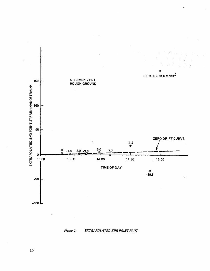
Once the ind iv idua l loading end po in t s are determined, they are p l o t t e d vs. t i m e of day on a l i n e a r s c a l e , as i n f i g u r e 4. A series of t en t o f i f t e e n loadings customarily takes from two t o twelve hours t o complete, depending upon the material, i t s su r face condi t ion, and t h e des i red end poin t accuracy. Over such t i m e i n t e r v a l s , s l i g h t zero d r i f t s of t h e order of one t o t en nano- s t r a i n are d i f f i c u l t t o avoid. With the stress loads and t h e y i e ld values a l t e rna ted at each succeeding load, zero o f f s e t and zero d r i f t are r e a d i l y evaluated from t h e t i m e p l o t and subt rac ted from t h e end poin t data . Although t h i s should fu rn i sh t r u e y i e l d da t a , another systematic f a c t o r e n t e r s t h e p i c t u r e when specimens of very low y i e l d are t e s t ed . Brit t le specimens which have had 0.2 mm o r more etched or lapped from t h e i r test sec t ion diameter, exh ib i t a "negative hys t e re s i s " or "negative y ie ld" e f f e c t p ropor t iona l t o the f i r s t power of appl ied torque, This e f f e c t is repea tab le but v a r i e s with material. The "moduli of negat ive y ie ld ," normalized f o r specimens of 7.6 mm diameter are as follows:
2 Material Nodulus, TN/m
S i l i con - 24,000
7971 ULE S i l i c a
CER-VIT
- 6,200
- 5,700
It is i l l o g i c a l t o assume t h a t t h i s e f f e c t occurs i n t h e test sec t ion of t h e specimen, "over-reacting" t o the appl ied stress, The de f l ec t ions , roughly one mi l l i on th of t h e de f l ec t ion under load, are most probably t h e r e s u l t of s m a l l e l a s t i c and v i s c o e l a s t i c s t r a i n s i n the specimen shoulder , r eac t ing with the cemented attachment t o t h e extensometer cups. A s t h i s attachment does not change with the test s e c t i o n diameter, t h e e f f e c t is more properly descr ibed as an angle vs . torque r e l a t ionsh ip r a t h e r than s t r a i n vs. stress, To determine the magnitude of t he e f f e c t i n terms of apparent negat ive s t r a i n vs. stress i n a given test, the above moduli are mul t ip l ied by t h e fou r th power of t h e r a t i o of t h e re ference diameter (7.6 mm) t o t h e test sec t ion diameter. (See Appendix E.) T e s t stress l e v e l s are divided by the r e s u l t i n g appl icable modulus t o y i e l d the instrumental "negative yield" s t r a i n . These values of s t r a i n are added t o the ex t rapola ted zero-corrected y i e l d s t r a i n values and t h e r e s u l t is the test sec t ion t r u e y i e ld s t r a i n (negative y i e l d e f f e c t e l iminated) . etched condi t ion, a negat ive y i e l d modulus was not determined, and the modulus f o r ULE s i l i c a w a s used t o reduce the f i n a l po l i sh d a t a ,
A s t h e 7940 s i l i ca w a s not t e s t e d i n the
9
150
z d
2 100
d
I- o 0 z 2-
z I- o I-
2 50 z n
a 2
z W
4 ~
2 0 2 1:
-50
-100
0
STRESS = 31.0 MNl'TI12 SPECIMEN 21 1-1 ROUGHGROUND
ZERO DRIFT CURVE 11.2 0 I
13:30 14:OO 14:30 15:OO
TIME OF DAY 0
-19.8
figun 4: EXTRAPOLATED END POINTPLOT
10

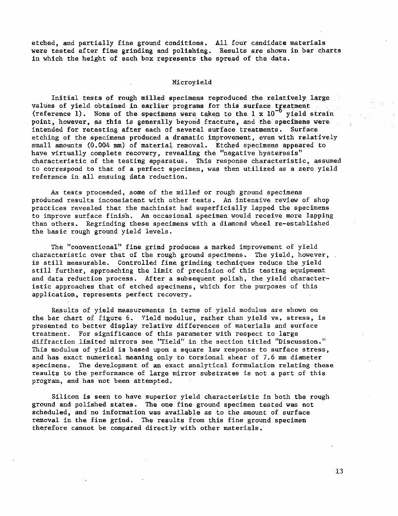
These cor rec ted end po in t y i e l d s t r a i n values are p l o t t e d vs. stress on a log-log p l o t . A r ep resen ta t ive p l o t is shown i n f i g u r e 5. The curves so formed tend t o b e s t r a i g h t l i n e s with a s l o p e of one-half f o r a l l materials t e s t e d i n t h i s program, suggest ing t h a t t h e y i e l d v a r i e s as t h e square of t h e stress. A s t h i s appears t o be a genera l r u l e f o r t h e b r i t t l e materials of t h i s test program, a pseudo-modulus of y i e l d 5 such tha @ y i e l d ) was developed t o allow convenient c behavior. That t h i s is no t a t r u e b complete dependence upon su r face con is f i n a l l y cor rec ted f o r test s e c t i o n diameter as
The magnitudes of delayed e las t ic s t r a i n of t h e m a t widely i n magnitude, b u t e x h i b i t a s t rong p ropor t iona l i t y t o stress divided by t i m e a f t e r release of stress. such t h a t
A modulus of delayed elastic s t r a i n
S t r e s s
where
E = s t r a i n a t 50 seconds a f t e r release of stress 50
and
= s t r a i n a t 100 seconds a f t e r release of stress 10 0 E
w a s u t i l i z e d t o compare v i s c o e l a s t i c behavior of d i f f e r e n t materials wi th var ious su r face condi t ions.
A t h i r d modulus, t h e f a m i l i a r e las t ic shear modulus G, w a s der ived from specimen de f l ec t ion under load f o r t h e materials t e s t ed . This adds l i t t l e t o b a s i c knowledge of t he materials, bu t provides a comparison t o t h e o the r moduli.
RESULTS
In the following desc r ip t ion of r e s u l t s , stress is expressed i n metric u n i t s of newtons per square meter. A conversion f a c t o r t o t h e English system is :
1 meganewton pe r square meter = 145 p s i
Two candidate mir ror s u b s t r a t e materials, CER-VIT and 7971 s i l i ca , were t e s t e d i n var ious states of su r face condi t ioning, inc luding rough mi l l i ng , e tch ing , and f i n e gr inding. S i l i c o n w a s given cursory tests i n mi l led ,
11

ULE 21 1-1 ROUGH GROUND
INTERCEPT 9.8MN/m2
0 0
,/0 /’
0 0
0
0
MODULUS OF YIELD - 0.1 TN/m2
1 10 100
YIELD STRAIN (UNITS OF ONE NANOSTRAIN)
figure 5: YIELD STRAIN VS STRESS
etched, and p a r t i a l l y f i n e ground condi t ions. A l l four candida te materials w e r e t e s t e d a f t e r f i n e gr inding and pol ishing. i n which t h e he igh t of each box r ep resen t s t h e spread of t h e da ta .
Resul t s are shown i n b a r c h a r t s
Microyield
I n i t i a l tests of rough mi l led spec values of y i e l d obtained i n earlier pro ( re ference 1). po in t , however, as t h i s is genera l ly beyond f r a c t u r e , an intended f o r r e t e s t i n g a f t e r each of several su r face t r e tch ing of t h e specimens produced a dramatic improvement, even with r e l a t i v e l y s m a l l amounts (0.004 mm) of material removal. Etched specimens appeared t o have v i r t u a l l y complete recovery , revea l ing t h e "negative hys te res i s ' ' c h a r a c t e r i s t i c of t h e t e s t i n g apparatus . This response c h a r a c t e r i s t i c , assumed t o correspond t o t h a t of a p e r f e c t specimen, w a s then u t i l i z e d as a zero y i e l d re ference i n a l l ensuing da ta reduct ion.
None of t h e specimens
ce
A s tests proceeded, some of t he mi l led o r rough ground specimens produced r e s u l t s i ncons i s t en t with o the r tests. An i n t e n s i v e review of shop p r a c t i c e s revealed t h a t t h e machinis t had s u p e r f i c i a l l y lapped the specimens t o improve s u r f a c e f i n i s h . than o the r s , Regrinding t h e s e specimens wi th a diamond wheel re-establ ished t h e b a s i c rough ground y i e l d levels.
An occas iona l specimen would r ece ive more lapping
The "conventional" f i n e gr ind produces a marked improvement of y i e l d c h a r a c t e r i s t i c over t h a t of t h e rough ground specimens. The y i e l d , however, i s s t i l l measurable. Control led f i n e gr inding techniques reduce t h e y i e l d s t i l l f u r t h e r , approaching t h e l i m i t of p rec i s ion of t h i s t e s t i n g equipment and d a t a reduct ion process. Af t e r a subsequent po l i sh , t h e y i e l d character- i s t i c approaches t h a t of etched specimens, which f o r t h e purposes of t h i s app l i ca t ion , represents pe r fec t recovery.
Resul ts of y i e l d measurements i n terms of y i e l d modulus are shown on t h e b a r char t of f i g u r e 6. Yield modulus, r a t h e r than y i e l d vs. stress, i s presented t o b e t t e r d i sp lay relative d i f f e rences of materials and su r face t reatment . For s ign i f i cance of t h i s parameter with respec t t o l a r g e d i f f r a c t i o n l imi ted mir rors see "Yield" i n t h e s e c t i o n t i t l e d 'tDiscussion. It This modulus of y i e l d is based upon a square l a w response t o su r face stress, and has exact numerical meaning only t o t o r s i o n a l shear of 7.6 mm diameter specimens. The development of an exact a n a l y t i c a l formulat ion r e l a t i n g these r e s u l t s t o t h e performance of l a r g e mirror s u b s t r a t e s is no t a p a r t of t h i s program, and has no t been attempted.
S i l i c o n is seen t o have supe r io r y i e l d c h a r a c t e r i s t i c i n both t h e rough ground and pol ished states. scheduled, and no information w a s a v a i l a b l e as t o t h e amount of s u r f a c e removal i n t h e f i n e gr ind. The r e s u l t s from t h i s f i n e ground specimen the re fo re cannot be compared d i r e c t l y with o t h e r materials.
The one f i n e ground specimen t e s t e d w a s no t
13

A a w
g 1.00 w
3
a a $
0.8 w n * 2
0.6 a a I- w - >
0.4 9 : u. 0 * 0.2
n 2 3
0 5
CONVENT1 ONAL FINE GROUND
Z K t
d 2 E z 3 0 0 O R ?
-
-
-
- tza
’
CONTROLLED FINE GROUND
YIELD STRAIN = (STRESS/M#
NOTES:
FINE GROUND WITH 600 MESH BORON CARBIDE UNSCHEDULED
FINE GROUND WITH 600 MESH BORON CARBIDE TO A DEPTH OF 0.04 mm VALUES GREATER THAN 1.0 ARE SHOWN AS 1.0
Figure 6: MODUL US O f YIELD
POLISHED
14

CER-VIT has a l a r g e r value of y i e l d modulus (lower y i e l d ) than t h e ULE s i l i ca with similar s u r f a c e t reatment , bu t t h e d i f f e r e n c e is r e l a t i v e l y s m a l l . A few tests of ULE s i l ica i n a p a r t i a l l y f i n e ground condi t ion, f ab r i ca t ed i n most cases without measurement of su r face removal, imply gradual improvement of y i e l d c h a r a c t e r i s t i c with depth of f i n e gr inding.
Af te r rough gr inding , p a r t i a l f i n e gr inding , o r conventional f i n e gr inding t h e hea t t reatment discussed under "Specimen Preparat ion" i n t h e s e c t i o n t i t l e d "Tes t Specimens" w a s requi red t o s t a b i l i z e s u r t o provide reproducible test r e s u l t s . Af t e r con t ro l l ed f i n e sh t reatment , however, adequate s t a b i l i t y w a s obtained without hea t (heat treat only s t a b i l i z e s su r face c racks) .
and
Delayed Elastic S t r a i n
The s e n s i t i v i t y and r e so lu t ion requi red of t he test equipment t o measure t h e small y i e l d s t r a i n s of t h i s test program s t rong ly i l lumina ted t h e delayed e las t ic s t r a i n c h a r a c t e r i s t i c s of t h e test materials. Delayed elastic, visco- elastic, o r t i m e dependent s t r a i n , as i t is var ious ly termed, is obviously a t r u e body material c h a r a c t e r i s t i c as opposed t o s u r f a c e e f f e c t s . It v a r i e s by orders of magnitude between materials, and i s only moderately inf luenced by su r face treatment. Figure 7 shows i n b a r cha r t form t h e range of values of delayed e las t ic modulus measured f o r t h e test materials of t h i s program.
S i l i c o n is seen t o have the h ighes t modulus ( f a s t e s t r e t u r n ) and CER-VIT t h e lowest modulus of delayed elastic s t r a i n (slowest r e t u r n t o rest p o s i t i o n ) . The si l icas take a pos i t i on c l o s e t o t h e geometric mean between these two responses.
Delayed elastic s t r a i n i n CER-VIT is v i r t u a l l y independent of su r f ace treatment , probably because t h e i n t r i n s i c low modulus overpowers any su r face e f f e c t . A s t h e modulus of t h e material increases t h e su r face e f f e c t s are more e a s i l y observed, as i n t h e s i l icas and s i l i c o n . The rough ground su r faces appear t o lower t h e e f f e c t i v e modulus as compared t o t h e etched su r faces . Differences of modulus with depth of e tch is apparent i n ULE s i l i c a . The apparent lowering of the.delayed elastic modulus with con t ro l l ed f i n e gr ind and pol i sh ing on t h e si l icas and s i l i c o n may be due t o e f f e c t s of t h e viscous damping system a t tached t o the extensometer becoming apprec iab le a t s h o r t t i m e i n t e r v a l s a f t e r release with reduced-diameter, low-st i f fness test sec t ions . It would appear unl ike ly t h a t t h e f i n e gr inding o r po l i sh ing t reatments themselves are res ponsib le.
Elas t i c Shear
Values of elastic shear modulus (G) were der ived from the specimen de f l ec t ions under load f o r the four test materials. Within t h e reproduc- i b i l i t y of t h e test equipment, t h i s modulus w a s independent of specimen t reatment o r su r f ace condi t ion. The modulus i s suppl ied he re t o compare
15

10
1
trm
era
Ra
E2a
ROUGH CONVENTIONAL CONTROLLED GROUND FINE GROUND FINE GROUND
NOTES:
ETCHED 5 p m ETCHED 30 pm
ea
POLISH ED
STRESS STRAIN = MDE t
t = TIME AFTER RELEASE OF STRESS
ETCH ED
R&re 7: DElA YED ELASTIC MODULUS
16

with t h e o the r moduli measured. Figure 8 shows t h e range of values determined f o r t h i s modulus of each material.
DISCUSSION
Yield S t r a i n
of modulus of n a l l materials S d 0.8 teranewto
cont ro l led f i n e gr ind and pol i sh ing treatment. The f i r s t obvious ques t ion t o be asked is, what does t h i s mean i n terms of a l a r g e mir ror s u b s t r a t e . Because t h e e f f e c t is apparent ly caused by su r face de fec t s , and w i l l b e inf luenced s t rong ly by s u b s t r a t e geometry, exact values w i l l r equ i r e ex tens ive ana lys i s and computation. It should b e v a l i d t o assume, however, t h a t t h e tes t specimen geometry u t i l i z e d i n t h i s program is much more s e n s i t i v e t o t h e su r face y i e l d e f f e c t than any p r a c t i c a l l a r g e mir ror s u b s t r a t e . For a given stress l e v e l , t he re fo re , t h e apparent y i e l d s t r a i n exhib i ted by t h i s test specimen geometry should b e an upper l i m i t t o t h e apparent y i e l d s t r a i n of a l a r g e mir ror s u b s t r a t e . I f w e assume a maximum peak shear stress l e v e l i n t h e mir ror su r face of 80 meganewtons pe r square meter (11,600 p s i ) , which approximates t h e breaking s t r eng th of most such b r i t t l e s t r u c t u r e s , our specimen w i l l have a y i e l d of less than 1 x A s t r u c t u r e of maximum dimension of 3 meters and a uniform s t r a i n of 1 x w i l l e x h i b i t a def lec- t i o n of 30 nanometers, o r roughly 1/130 t h e wavelength of 400 nanometer v i s i b l e l i g h t . "his dimension is less than common cri teria f o r f igu r ing a high grade d i f f r a c t i o n l imi ted mir ror .
A s s t a t e d above, t h i s e f f e c t i v e y i e l d i s regarded as an upper l i m i t and a p r a c t i c a l mir ror s u b s t r a t e should exh ib i t less y i e l d by more than an o rde r of magnitude. As a l l four materials t e s t e d had y i e l d moduli exceeding 0.8 TN/m2 when t h e su r face is c a r e f u l l y f i n e ground and pol ished, t h e s u r f a c e y i e l d c r i t e r i o n should not be important i n t h e choice of a s u b s t r a t e material.
Delayed Elastic S t r a i n
Delayed elastic s t r a i n is important i n an o p t i c a l system when accura t e f i g u r e is required a s h o r t t i m e i n t e r v a l a f t e r being subjec ted t o high stress levels from mechanical o r thermal loading. L e t us consider CER-VIT, which has t h e lowest delayed s t r a i n modulus (two teranewtons per square meter- second) of t h e four materials t e s t ed . When subjec ted t o a stress of 80 meganewtons pe r square meter, which approaches i t s u l t ima te s t r e n g t h i n shea r , i t w i l l r t a i n a s t r a i n of 4 x one second a f t e r load release, 6.7 x a t one minute, and 1.1 x a t one hour. Assuming worst case, as i n t h e previous sec t ion , a t h r e e meter CER-VIT mir ror s u b s t r a t e subjec ted t o breaking s t r eng th load should recover t o wi th in t h e d i f f r a c t i o n l i m i t c r i t e r i o n wi th in one hour. s e c ) t h e recovery would t ake p l ace wi th in t h r e e minutes, and f o r s i l i c o n
For a s i l i ca mir ror (modulus = 40 TN/m2 -
17

7940 SILICA CER-VIT ULE
SILICA SILICON
figure 8: ELASTIC SHEAR MODULUS
18
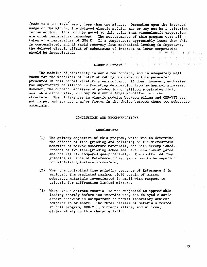
2 (modulus = 200 TN/m -sec) less than one minute. usage of t h e mir ror , t h e delayed elastic modulus may o r may no t b e a c r i t e r i o n f o r s e l ec t ion . are o f t en temperature dependent. taken a t a temperature of 306 K. is contemplated, and i f r ap id recovery from mechanical l o t h e delayed elastic e f f e c t of s u b s t r a t e s of i n t e r e s t a t 1 should be inves t iga ted .
Depending upon t h e intended
It should be noted at t h i s po in t t h a t v i s c o e l a s t i c p rope r t i e s The measurements of t h i s program were a l l I f a temperature appreciably lower than t h i s
Elastic S t r a i n
The modulus of e l a s t i c i t y is not a new concept, and is adequately w e l l known f o r t h e materials of i n t e r e s t making t h e d a t a on t h i s parameter presented i n t h i s r e p o r t r e l a t i v e l y unimportant. It does, however, emphasize t h e s u p e r i o r i t y of s i l i c o n i n r e s i s t i n g deformation from mechanical stresses. However, t h e cur ren t processes of production of s i l i c o n s u b s t r a t e s l i m i t a v a i l a b l e mir ror s i z e , and may r u l e out a l a r g e monoli thic s i l i c o n s t r u c t u r e . The d i f f e rences i n elastic modulus between s i l i ca and CER-VIT are not l a rge , and are no t a major f a c t o r i n t h e choice between these two s u b s t r a t e materials.
CONCLUSIONS AND RECOMMENDATIONS
Conclusions
(1) The primary ob jec t ive of this program, which w a s t o determine t h e e f f e c t s o f ' f i n e gr inding and pol i sh ing on t h e mic ros t r a in behavior of mirror s u b s t r a t e materials, has been accomplished. E f fec t s of two f ine-gr inding schedules have been inves t iga t ed and t h e r e s u l t s compared quan t i t a t ive ly . The cont ro l led f i n e gr inding sequence of Reference 3 has been shown t o be super ior f o r minimizing su r face microyield.
(2) When the con t ro l l ed f i n e gr inding sequence of Reference 3 is employed, t h e pred ic ted maximum y i e l d s t r a i n of mir ror s u b s t r a t e materials inves t iga t ed i s s m a l l wi th r e spec t t o cr i ter ia f o r d i f f r a c t i o n l imi t ed mir rors .
(3) Where the s u b s t r a t e material is not subjec ted t o apprec iab le loading s h o r t l y before its intended use, t h e delayed elastic s t r a i n behavior i s unimportant a t normal labora tory ambient temperature o r above. The t h r e e classes of materials t e s t e d
d i f f e r widely i n t h i s c h a r a c t e r i s t i c . gram, CER-VIT, v i t r e o u s s i l ica , and s i l i c o n ,
19
( 4 ) Of t h e materials t e s t e d i n t h i s program, s i l i c o n is outstanding i n i t s elastic, delayed elastic, and su r face y i e l d p rope r t i e s .
Of t h e materials o the r than s i l i c o n t e s t e d i n t h i s program, no c l e a r s u p e r i o r i t y i s evident. delayed elastic s t r a i n e f f e c t s , but t h i s is of l i t t l e s i g n i f i c a n c e i n conventional t e l e scope mir ror usage.
(5) CER-VIT shows d r a s t i c a l l y g r e a t e r
Recommendations
The ob jec t ives of t h i s program have been m e t wi thout s i g n i f i c a n t unanswered questions. This program w a s l imi t ed i n i t s ob jec t ives , however, and several areas remain t o be explored. These are d e t a i l e d as follows:
Thermal e f f e c t s . Delayed e l a s t i c s t r a i n , a l though r e l a t i v e l y unimportant a t 300 K , may be s i g n i f i c a n t a t lower temperatures. Determination of t h e thermal dependence of t h i s c h a r a c t e r i s t i c , e s p e c i a l l y f o r CER-VIT, i s recommended.
Creep. P a s t eva lua t ion of t h e v i s c o s i t y of g l a s sy materials i n t h e 300 K temperature range i s a t b e s t con t rove r s i a l . of c u r r e n t l y accepted e leva ted temperature v i s c o s i t y f i g u r e s t o temperatures approaching 300 K i s recommended.
Extension
Beryllium. Or ig ina l ly intended f o r test i n t h i s program, copper a l l o y s of beryl l ium w e r e removed from cons ide ra t ion by l i m i t a t i o n s of funding and calendar test t i m e . Beryllium and i ts a l l o y s are s t i l l of i n t e r e s t f o r mir ror s u b s t r a t e f a b r i c a t i o n . The p r e c i s e nanos t ra in behavior of t h e e m a t e r i a l s remains t o b e documented, and should be considered. 7

I :
APPENDIX A
Material S i l i c o n
Reagent
SPECIMEN SURFACE TREATMENT
Etch Formulations
HF 14%
m03 32%
H2S04
C2H300H
H2°
27%
27%
G r i t
Conventional Fine Grind
#400 S i l i c o n Carbide R225 Aluminum Oxide #125 Aluminum Oxide 1'195 Aluminum Oxide
Controlled Fine Grind
8240 Boron Carbide f600 Boron Carbide 1'115 Diamond 116 Diamond
ULE S i l i c a CER-VIT
50% 10 %
10 %
50% 80 %
Fine Grind Schedules
G r i t Diameter Surface Removal Micrometers Micrometers
45 22 12 9
60 30 15
6
60 28 18 10
480 180 90 45
Po l i sh
Rouge
21

APPENDIX B
SPECIMEN HISTORY I
Material SIN* TIN*
S i l i c o n 201 1
Treatment
Rough ground, annealed Destroyed i n anneal
---
202 1 Rough ground, annealed Destroyed i n anneal
203 1 Rough ground, p a r t i a l l y f i n e ground (unscheduled) , h e a t t r e a t e d
0.61
2 Control led f i n e ground, pol ished
.1.0
204 Rough ground, heat t r e a t e d 1
2
0.35
>1.0
>1.0
Diameter etched 120 u m
3
ULE S i l i c a 211 1
212 1
2
3
Controlled f i n e ground, pol ished
Ground, s u p e r f i c i a l l y lapped, h e a t t r e a t e d . Broken i n test
0.10
Rough ground, h e a t t r e a t e d , diameter etched 200 1-1 m
>1.0
D i a m e t e r etched a d d i t i o n a l 50 u m
>1.0
0.68 Reground (rough) p a r t i a l l y f i n e ground (unscheduled), h e a t t r e a t e d
4 Conventional f i n e ground, h e a t t r e a t e d
0.75
5 Reground (rough), h e a t t r e a t e d
0.15
*SIN - Specimen number T/N = Test number
22

APPENDIX B (Continued)
Material S/N*
ULE S i l i c a 212
213
- T /N* Treatment
6 Control led f i n e ground
7 Polished
1 
heat t r e a t e d
2
2 14 1
2
215 1
2
3
CER-VIT 101 221 1
222 1
223 1
2
224 1
2
Heat t r e a t e d , diameter etched 8 1.1 m Broken i n test
Rough ground, s u p e r f i c i a l l y lapped, hea t t r e a t e d
Fine ground .083 mm on diameter with #600 boron carbide. Broken i n test
Rough ground, hea t t r e a t e d
Controlled f i n e ground
Yield M2dulus, TN/m
0.95
>1.0
0.12
0.56
0.12
0.91
Pol ished 0.93
Rough ground, hea t t r e a t e d --- Broken i n mounting
Rough ground, heat t r e a t e d --- Broken i n mounting
Rough ground, p a r t i a l l y 0.35 f i n e ground (unscheduled) hea t t r e a t e d
H e a t t r e a t e d , diameter >1.0 etched 70 1.1 m Broken i n test
Rough ground, p a r t i a l l y f i n e 0.38 ground (unscheduled), heat t r e a t e d
Heat t r e a t e d , diameter etched 10 1.1 m
>1.0
23

APPENDIX B (Concluded)
Material S/N* - T/N* Treatment Yield M?dulus,
TN/m
CER-VIT 101 224 3 Heat t r e a t e d , diameter etched >1.0 a d d i t i o n a l 10 p m
4
225
S i l i c a 7940 231
232
5 Conventional f i n e ground, 0.83 hea t t r e a t e d
6 Reground (rough), hea t t r e a t e d 0.16
6
1
Controlled f i n e ground
Pol ished
Rough ground, s u p e r f i c i a l l y f i n e ground, hea t t r e a t e d
Conventional f i n e ground
H e a t t r e a t e d
Reground (rough), hea t t r e a t e d
Controlled f i n e ground, hea t t r e a t e d
Pol ished
Rough ground, con t ro l l ed . f i n e ground, pol ished
1 Rough ground, con t ro l l ed f i n e ground, pol ished
1.0
>1.0
0.23
poor d a t a
0.76
0.20
0.99
>1.0
1.0
0.90

APPENDIX C
DELAYED ELASTIC STRAIN EXTRAPOLATION
Determination of End Po .-
Assumption :
The time history of a rest specimen after re1 of represented closely by the expression
B A = - + K t
where: A is the total instantaneous strain
B is a factor representing the delayed elastic strain at unity time
t is time after release of load
K is the end point or steady state strain
Let us take time intervals t and t such 1 2 that
t2 = 10 t1
then
B = tl(A1 - K) t2(A2-K)
and
2 t - . A2 - A1
K = - -
or
25

APPENDIX C (Concluded)
Determination of Delayed Elastic Modulus
If we take times t of 50 and 100 seconds and subscript the parameters A accordingly, we have
= - + K AIOO 100
B B B = - - - = - A50 - AIOO 50 100 100
B = 100(A50 - Aloe) and Delayed Elastic Modulus is found by
= stress/100*(A50 - Aloe)
26
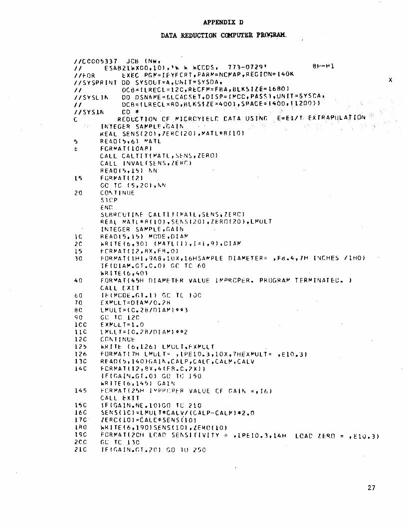
APPENDIX D
DATA REDUCTION COMPUTER PRWW
t
5 c
15
2c
1c 2 c 15 3c
40
6 0 70 8 C 9 0 1cc 11c 1 2 c 125 1 2 6 13C 1 4 C
1 4 5
15C 1 b G 1 7 C l R 0 19c 2cc 21c
/ / C C C O 5 3 3 7 JCH (NWr / / E S A B 2 l k X C O ~ l O ) r ’ k h hCCCSI 773-0729’ 8P-P 1 / / F O R / / S Y S P R I Y T 00 S Y S O U T = A r C h I T = S Y S O A v / / O C 8 = 1 L R E C L = 1 2 C r R t C F C = F H A , B L K S I Z E = l b R O ) / / S Y S L I F , OD D S N A V E = C L C A C / / D C R = I L R E C L = 8 0 r H / / S Y S L h CD *
E X E C P G P / = I F YF CP T 9 F A R w = N C P A P 9 R E G ION= W O K X
R E O U C T I ON P I C R C Y I E L T : C A T A U S I N G I K T E G t i R S A V P L H E A L S E N S ( 2 0 1 , I E R C ( 2 0 ) r P A T L * R ( 1 0 1
27

APPENDIX D (Continued)
2 ZC 2 3 C
S E h S ( G A I N 1 =E X V L L T * C A L V * ? O/ ( C A L P - C A L C 7 E R C I GA I h I = C A L C * S E hS ( G A I N ) k H I T E ( 6 9 2 3 5 ) G A I N . S E N S ( G A I N ) r Z E R O I G A I N )
235 f O R P A T I 1 3 H G A I N N L P R E H = , 1 4 ~ 1 0 X , 1 2 H S E N S I T I V I T Y = * l P E 1 1 * 4 * l O % * 1 5 H Z E R O = r E 11.4 1
2 4 C GT: TC 1 3 C 2 5 C C O N T I N U E
R E T L R N E h C S b B R O U T I N E I N V A L ( S E N S * Z E H O I R E A L S E N S ( 2 O ) r Z F R C ( 2 0 ) ~ L S T R N I L B E ~ O I L O A D V I N T E G E R G A I N
C C O C P L T E S I h G L E P O I N T V A L U E S B Y F O R M U L A E X T H A P U L A T I O N 2 8 5 k R I T E ( 6 9 2 8 6 ) 2 6 C H E A D f 5 * 7 7 0 ) G A l h * L C A D V p E L V e E W V * E l V ~ E X V M l O * E X V 2 7 C F O R V A T ( I Z * ~ X * ~ ( F R . C S ~ X ) 1 2 8 0 I F ( G A I N o G T e 2 Q ) GC TU 3 7 0 . 286 F O R C A T ( l H O ~ Z C X ~ 4 1 H S I N G L E P C I N T V A L U E S - F C R P U L A E X T K A P O L A T ION/ lHO/ 19
1 X ~ 5 H Y I ~ L D ~ 6 X ~ 4 H L C A C ~ ~ X ~ 5 H L C ~ ~ , ~ 7 X ~ 7 H L A T E R A L / 6 X ~ 6 ~ S T R E S S ~ 6 % ~ 6 H S T H A f 2 N r 6 X * 6 t ! S T R A I h 1 , 6 X * 7 H ~ E ~ C t h 1 ~ r S X , 7 H B E N D I N G / 1H 1
29C S T R E S S = L C A l ? V * S E N S ( l O ) - Z F R O ( 1 0 ) 3 C C Y I E L D = l . l l l * S E h S ( G A l h ) * ( E X V - O ~ l * E X V ~ l O ~ - Z E R C ( G A I N ~
IF (E lV .EC,C .O) G C T C 3 3 5 3 1 C L B E N D ~ ~ E L V * S E Y S ~ 1 1 l - Z E R 0 o ) / 1 2 ~
3 3 G L S T H N = € l V * S E N S f 1 ) - L t K C ( l l 3 2 C k B E N C = ~ E k V * S F N S ( L 2 ) - Z t R C ~ 1 2 1 ~ / 1 2 ~
GO TO 340
k B E h C = O , C LSTRN=O,C
3 3 5 L B E h D = C e C
3 4 0 h R I T E ( 6 r 3 5 0 ) S T Y E S S * Y I E L D * L S T R Y * L H E N D * W B E N D 3 5 C F C H P A T f 1H 9 2 X r 5 ( 1 P E 1 2 . 3 ) ) 3 6 C C C TC 2 6 C 37C R E T I J K N
E A C / * / / L K E D E X F C P G ~ = L I N K E D I T ~ C O N D = ( 5 , L T ) , R E G I O N = l 4 O K / / S Y S P R I N T DD S Y S O b T = A * L h I T = S Y S D A * / / D C B = ( L R E C L = 1 2 l r R E C F ~ = F B A 1 8 L K S I Z E = l 5 7 3 ) / / S Y S L I6 U f l 01 S P = S H R * C S h 1 A M E = S Y S l , F O K r L 1H / / S Y S L p O D DD ~ Y I T = S Y S D A r D I S P = ( * P A S S ~ * C S N A ~ F = ~ & ~ D S ( ~ E ~ B l * / / S P A C E = ( 1 0 2 4 r ( 2 0 0 ~ 1 0 ~ l ~ ~ R ~ S E ) r C C B = B L K S I L E ~ l ~ 2 4 / / S Y S C I T l 00 L N I T = S y S O A , S f ‘ A C E = ( ~ 2 5 0 1 ( 2 5 0 * S ) r R C S t ) r C C E = B L K S I Z ~ = 1 ~ ~ 4 / / S Y S L I N DD P S N A p E = 2 L O A D S E T r D I SP= O L E C € L f T E 1 / / G O t X E C PGY=*. L K E D . S Y S L MCD ,CTKC= ( 5 9 L 1 9 L K f C 1 * R E G 10N= 1 4 0 K //FTCSFCCl CD C C N A h ’ E = S Y S I h
/ / F T 0 6 F C O l DD S Y S 3 U T = A * G h l T = S Y S D A * X
/ / F T C B F C C l DD D S N A ~ E = E E R h ~ D I S P = ( N E W ~ C E L E T E ~ ~ U N ( T = S Y S D A ~ X
/ / D C B = ( L Q E C L = ~ ~ C I R E C F ~ - F C A I H L K S I Z € = ~ ~ ~ O )
/ / D C R = ~ L R E C L = R O ~ R E C F ~ = F R I H L K S l Z E = 4 O O ~ ~ S P A C ~ ~ ( ~ ~ ~ , ~ ~ / / S Y S I R OD * e 1 C . 3 C 1
C A T E 4 / 4 / 7 2 U L E 211-1 A S GHCUhtD
1 c C, 9 9 5 5 -0 . C C O Y - 0 . Y 9 5 A 9 1 ,5
X

APPENDIX D (Concluded)
11 12 0 1 c 4 3c c 4 04 64 c 4 0 4 c 4 c4 04 04 3c C?
C.0180 CoC177 0.02co 1,9951
Coo106 -C, 02 14
-0,0492 C - 0 6 7 2
C . 1 5 1 1 -0 ,2692 0.4289
Coo258
-0.1045
-0.CC28 -0,0246 1,00€-05 -C,CC32 -0.0245 LeOOf-05 - 0 , COO8 -0,0219 1.00E-05 G o C CCO -1 .9837 1o00f-06
- 0 , C036 -0,0024 o.ccc0 -0.0048 - 0 o C O 2 R -0.0011
0 , o c c o -0,0131 - O * C O 2 2 ~ 0.0061 c , c c c o -0,031 5 0. o o c o n . O O 5 5
0, OR20 -0,1226
-1 ,5430 7,0100
0,0139 0,0067
0,4434 0 ,328Y
29

APPENDIX E
ADJUSTMENT OF NEGATIVE YIELD MODULUS TO TEST DIAMETER
Assume that the I'n is a function only of t
Thus
n per unit length (a)
a = K T
The apparent specimen strain (E) is found by 1 ~ = - d a 2
where d is the specimen test section diameter.
The stress (S) exerted upon the test section by the torque T is 16T s = -
3 rd
so that the "Modulus" of negative yield M is
The "modulus" so defined is obviously a function of diameter. If we have the modulus defined at a particular diameter d and wish to determine the effective apparent negative yield strain at a 8ifferent diameter d 1' then we have
S 4 Mo (do/dl)
€1 = and
APPENDIX F
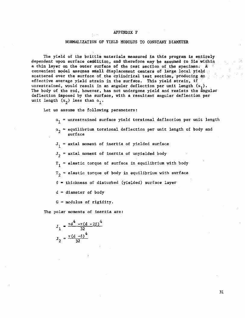
NORMALIZATION OF YIELD MODULUS TO CONSTANT DIAMETER
The y i e ld of t h dependent upon sur f a t h i n l a y e r on t h e
e f f e c t i v e average y unres t ra ined , would r e s u l t i n an angular de f l ec t ion per u n i t l ength (a1). The body of t he rod, however, has not undergone y i e l d and resists t h e angular de f l ec t ion imposed by the sur face , with a r e s u l t a n t angular de f l ec t ion per u n i t length (a2 ) less than 01 1'
L e t us assume t h e following parameters :
a = unrestrained sur face y i e ld t o r s i o n a l de f l ec t ion per u n i t l ength
a2 = equi l ibr ium t o r s i o n a l de f l ec t ion per u n i t length of body and
1
sur f ace
J1 = a x i a l moment of i ne r t i a of yielded su r face
J2 = axial moment of i n e r t i a of unyielded body
T1 = elastic torque of sur face i n equi l ibr ium with body
T2 = elastic torque of body i n equi l ibr ium with su r face
6 = thickness of d i s turbed (yielded) su r face l a y e r
d = diameter of body
G = modulus of r i g i d i t y .
The polar moments of i n e r t i a are:
4 - vd4 -v(d -28) J1 - 32
J2 = 32
4 m(d -6)
31

APPENDIX F (Continued)
If w e assume t h e thickness (6) of t h e d i s tu rbed s u r f a c e t o b e s m a l l wi th respec t t o t h e o v e r a l l diameter, t h e expressions f o r moment of i n e r t i a reduce t o
J1 = 114 n6d3
J2 = 1/32 n d 4
The elastic torques exer ted upon two por equi l ibr ium are equal , and expressed by:
T1 = G J (a -a ) = 114 G (a1-a2)n6d 3 1 1 2
and
4 T2 = G J 01 = 1/32 G a2nd 2 2
thus
a2 = 8 a16/(86f d)
If w e again assume t h a t
w e may make t h e approximation
a2 =8 a1 6/d
L e t
y1 = y i e l d s t r a i n of s u r f a c e l a y e r
y2 = apparent y i e l d s t r a i n of combined su r face and body
then
32

APPENDIX F (Concluded)
For a given sur face y i e l d , this ind ica t e s the apparent y i e ld t o vary inverse ly as t h e test sec t ion diameter.
The pseudo-modulus M su r face condi t ions be’
o r
11 2 M = stress (d / (8 y l B ) ) Y
which implies t h a t t he observed modulus of y i e l d is propor t iona l t o the square root of t he specimen test sec t ion diameter. To normalize t h e r e s u l t s t o a given diameter d the operat ion ind ica ted by
0’
M (normalized) = M (apparent) e (do/d) 112 Y Y
must be performed.
33
REFERENCES
1. Eul, W i l l i a m A.; and Woods, W. W i l l i a m : Shear S t r a i n P rope r t i e s t o
10-l' of Selected Opt ica l Materials. NASA CR-1257 , 1969
2. Woods, W. W i l l i a m : Microyield P rope r t i e s of Teles
NASA CR-66886, 1970
3. S t o l l , R.; Forman, P. F.; and Edelman, J.: The E f f e c t of Di f f e ren t
Grinding Procedures on t h e S t rength of Scratched and Unscratched
Fused S i l i c a . Paper presented at Symposium s u r l a r e s i s t a n c e mecanique
du v e r r e e t les moyens de lamel ior , Union S c i e n t i f i q u e Contentale du
Verre (Florence) , September 25-29, 1961.
34