efficient and secured rekeying based key distribution in ... · efficient and secured rekeying...
TRANSCRIPT

University of Lethbridge Research Repository
OPUS https://opus.uleth.ca
Theses Arts and Science, Faculty of
Kabir, A.F.M. Sultanul
2015
Efficient and secured rekeying based
key distribution in wireless sensor
architecture with Arduino and XBee
Department of Mathematics and Computer Science
https://hdl.handle.net/10133/3679
Downloaded from OPUS, University of Lethbridge Research Repository

EFFICIENT AND SECURED REKEYING BASED KEY DISTRIBUTION INWIRELESS SENSOR ARCHITECTURE WITH ARDUINO AND XBEE
A. F. M SULTANUL KABIRMasters of Science, Royal Institute of Technology, 2009
A ThesisSubmitted to the School of Graduate Studies
of the University of Lethbridgein Partial Fulfillment of the
Requirements for the Degree
MASTER OF SCIENCE
Department of Mathematics and Computer ScienceUniversity of Lethbridge
LETHBRIDGE, ALBERTA, CANADA
c© A. F. M Sultanul Kabir, 2015

EFFICIENT AND SECURED REKEYING BASED KEY DISTRIBUTION INWIRELESS SENSOR ARCHITECTURE WITH ARDUINO AND XBEE
A. F. M SULTANUL KABIR
Date of Defense: April 24, 2015
Dr. Hua LiSupervisor Associate Professor Ph.D.
Dr. Gongbing ShanCommittee Member Professor Ph.D.
Dr. Robert BenkocziCommittee Member Associate Professor Ph.D.
Dr. Howard ChengChair, Thesis Examination Com-mittee
Associate Professor Ph.D.

Dedication
To my parents and wife.
iii

Abstract
Since the time of their introduction, Wireless Sensor Networks (WSN) have been catching
the interest of researchers. WSN have a wide range of applications, some even involving
sensitive and secret information, thereby raising security concerns. Nevertheless, WSN
have some constraints like limited memory, energy and computational capability, which
pose an obstacle for the addition of proper security in sensor nodes. This thesis introduces
a new rekeying design for WSN security framework whose implementation would dispense
effective security in the sensor nodes. This proposed security framework is endowed with
the capacity to address security issues, such as message integrity, confidentiality, authen-
ticity and freshness based on symmetric key cryptography. In addition, this design does
not allow the storage of any key except the initial master key in the sensor nodes prior to
network deployment. This thesis also investigates reconfigurable sensor nodes in terms of
execution time, memory, power consumption, and cost while running the security frame-
work. Finally, the findings of this thesis are compared with previous studies conducted in
this interesting field.
iv

Acknowledgments
First and foremost, I would like to render my utmost thanks and gratitude to my supervisor,
Dr. Hua Li, for his continuous guidance, support and cooperation throughout the journey
of my MSc program. His direction, valuable opinion and effort have led me on the path of
my thesis.
I wish to express my thanks to Dr. Robert Benkoczi for his encouragement and insight-
ful advice which certainly has helped me to ascertain my research objective. He took the
time to review my thesis and his valuable feedback has helped me in the successful comple-
tion of my thesis. My sincere thanks also to Dr. Gongbing Shan for his thoughtful advice
and invaluable feedback regarding my thesis work.
I am very thankful to all my fellow graduate students, family members and lab members
whose cooperation has made this path easier for me. Special thanks go to my wife for her
tremendous support, encouragement and help throughout my master’s program.
v

Contents
Contents vi
List of Tables ix
List of Figures x
1 Introduction 11.1 Motivation . . . . . . . . . . . . . . . . . . . . . . . . . . . . . . . . . . . 11.2 Main contribution . . . . . . . . . . . . . . . . . . . . . . . . . . . . . . . 31.3 Thesis organization . . . . . . . . . . . . . . . . . . . . . . . . . . . . . . 3
2 Background Study 52.1 Wireless Sensor Networks . . . . . . . . . . . . . . . . . . . . . . . . . . 52.2 Applications of Wireless Sensor Networks . . . . . . . . . . . . . . . . . . 62.3 Attacks on WSN . . . . . . . . . . . . . . . . . . . . . . . . . . . . . . . 6
2.3.1 Attacks on secrecy and authentication . . . . . . . . . . . . . . . . 62.3.2 Attacks on network availability . . . . . . . . . . . . . . . . . . . 72.3.3 Stealthy attack . . . . . . . . . . . . . . . . . . . . . . . . . . . . 72.3.4 Physical layer attacks . . . . . . . . . . . . . . . . . . . . . . . . . 72.3.5 Data link layer attacks . . . . . . . . . . . . . . . . . . . . . . . . 72.3.6 Network layer attacks . . . . . . . . . . . . . . . . . . . . . . . . 82.3.7 Transport layer attacks . . . . . . . . . . . . . . . . . . . . . . . . 92.3.8 Application layer attacks . . . . . . . . . . . . . . . . . . . . . . . 9
2.4 Performance Requirements in WSN . . . . . . . . . . . . . . . . . . . . . 102.4.1 Energy efficiency . . . . . . . . . . . . . . . . . . . . . . . . . . . 102.4.2 Memory requirement and execution time . . . . . . . . . . . . . . 10
2.5 Security Requirements in WSN . . . . . . . . . . . . . . . . . . . . . . . . 102.5.1 Confidentiality . . . . . . . . . . . . . . . . . . . . . . . . . . . . 112.5.2 Integrity . . . . . . . . . . . . . . . . . . . . . . . . . . . . . . . . 112.5.3 Authentication . . . . . . . . . . . . . . . . . . . . . . . . . . . . 112.5.4 Authorization . . . . . . . . . . . . . . . . . . . . . . . . . . . . . 122.5.5 Current Data . . . . . . . . . . . . . . . . . . . . . . . . . . . . . 122.5.6 Forward and backward secrecy . . . . . . . . . . . . . . . . . . . . 12
2.6 Symmetric Encryption . . . . . . . . . . . . . . . . . . . . . . . . . . . . 122.6.1 Cryptographic dimension . . . . . . . . . . . . . . . . . . . . . . . 13
2.7 RC4 . . . . . . . . . . . . . . . . . . . . . . . . . . . . . . . . . . . . . . 142.8 Hash Functions . . . . . . . . . . . . . . . . . . . . . . . . . . . . . . . . 16
vi

CONTENTS
2.8.1 Properties of Hash value . . . . . . . . . . . . . . . . . . . . . . . 162.9 Secure Hash Algorithm (SHA-1) . . . . . . . . . . . . . . . . . . . . . . . 172.10 IEEE 802.15.4 Protocol . . . . . . . . . . . . . . . . . . . . . . . . . . . . 182.11 ZigBee . . . . . . . . . . . . . . . . . . . . . . . . . . . . . . . . . . . . . 182.12 DigiMesh Network . . . . . . . . . . . . . . . . . . . . . . . . . . . . . . 20
3 Related Contributions and Motivation 21
4 Proposed Framework Design 264.1 Security Issues Attained by the Design . . . . . . . . . . . . . . . . . . . . 28
4.1.1 Confidentiality . . . . . . . . . . . . . . . . . . . . . . . . . . . . 284.1.2 Data integrity and authenticity . . . . . . . . . . . . . . . . . . . . 294.1.3 Forward and backward secrecy . . . . . . . . . . . . . . . . . . . . 29
4.2 Attack Prevention . . . . . . . . . . . . . . . . . . . . . . . . . . . . . . . 294.2.1 Man in the middle attack . . . . . . . . . . . . . . . . . . . . . . . 294.2.2 Reply attack . . . . . . . . . . . . . . . . . . . . . . . . . . . . . 294.2.3 Tampering . . . . . . . . . . . . . . . . . . . . . . . . . . . . . . 304.2.4 Sybil attack and hello flood attack . . . . . . . . . . . . . . . . . . 30
5 Hardware Component 315.1 Arduino . . . . . . . . . . . . . . . . . . . . . . . . . . . . . . . . . . . . 315.2 Arduino Uno . . . . . . . . . . . . . . . . . . . . . . . . . . . . . . . . . 315.3 Arduino XBee Shield . . . . . . . . . . . . . . . . . . . . . . . . . . . . . 335.4 XBee . . . . . . . . . . . . . . . . . . . . . . . . . . . . . . . . . . . . . 335.5 XBee Explorer USB . . . . . . . . . . . . . . . . . . . . . . . . . . . . . 345.6 Temperature Sensor TMP36 . . . . . . . . . . . . . . . . . . . . . . . . . 355.7 Related Sensor Motes . . . . . . . . . . . . . . . . . . . . . . . . . . . . . 36
5.7.1 TelosB . . . . . . . . . . . . . . . . . . . . . . . . . . . . . . . . 365.7.2 MicaZ . . . . . . . . . . . . . . . . . . . . . . . . . . . . . . . . . 375.7.3 Waspmote . . . . . . . . . . . . . . . . . . . . . . . . . . . . . . . 375.7.4 Shimmer . . . . . . . . . . . . . . . . . . . . . . . . . . . . . . . 38
6 Implementation of the Proposed Framework 396.1 Architecture of the System . . . . . . . . . . . . . . . . . . . . . . . . . . 39
6.1.1 Circuit and Wiring . . . . . . . . . . . . . . . . . . . . . . . . . . 396.2 System Programming Phase . . . . . . . . . . . . . . . . . . . . . . . . . 40
6.2.1 Communication establishment . . . . . . . . . . . . . . . . . . . . 406.2.2 Replacing the old key and rekeying . . . . . . . . . . . . . . . . . 426.2.3 Data transfer between the sensor nodes and the receiver . . . . . . . 436.2.4 Implementing the whole concept in Mesh network . . . . . . . . . 456.2.5 Graphical user interface on the receiver side . . . . . . . . . . . . . 46
7 Testing and Evaluation 497.1 Execution Time . . . . . . . . . . . . . . . . . . . . . . . . . . . . . . . . 497.2 Execution time for variable size of sensor data . . . . . . . . . . . . . . . . 51
7.2.1 Encryption . . . . . . . . . . . . . . . . . . . . . . . . . . . . . . 51
vii

CONTENTS
7.2.2 Signature generation . . . . . . . . . . . . . . . . . . . . . . . . . 527.3 Current consumption . . . . . . . . . . . . . . . . . . . . . . . . . . . . . 527.4 Energy consumption . . . . . . . . . . . . . . . . . . . . . . . . . . . . . 547.5 Introducing power saving on the sensor node . . . . . . . . . . . . . . . . 567.6 Comparison with previous works . . . . . . . . . . . . . . . . . . . . . . . 58
7.6.1 Execution time for k . . . . . . . . . . . . . . . . . . . . . . . . . 587.6.2 Current consumption . . . . . . . . . . . . . . . . . . . . . . . . . 597.6.3 Energy consumption . . . . . . . . . . . . . . . . . . . . . . . . . 607.6.4 Explanation for low energy consumption . . . . . . . . . . . . . . 61
7.7 Latency . . . . . . . . . . . . . . . . . . . . . . . . . . . . . . . . . . . . 627.8 Latency calculation in Digimesh . . . . . . . . . . . . . . . . . . . . . . . 647.9 Throughput . . . . . . . . . . . . . . . . . . . . . . . . . . . . . . . . . . 667.10 Throughput in Digimesh . . . . . . . . . . . . . . . . . . . . . . . . . . . 67
8 Conclusion and Future works 698.1 Conclusion . . . . . . . . . . . . . . . . . . . . . . . . . . . . . . . . . . 698.2 Future works . . . . . . . . . . . . . . . . . . . . . . . . . . . . . . . . . 70
Bibliography 72
viii

List of Tables
2.1 Facts regarding SHA-1 . . . . . . . . . . . . . . . . . . . . . . . . . . . . 18
4.1 Notation used in rekeying framework . . . . . . . . . . . . . . . . . . . . . 26
7.1 Execution time for a sensor node . . . . . . . . . . . . . . . . . . . . . . . 507.2 Current consumption by a sensor node . . . . . . . . . . . . . . . . . . . . 537.3 Current consumption by a sensor node including radio . . . . . . . . . . . 537.4 Energy consumption by a sensor node . . . . . . . . . . . . . . . . . . . . 55
ix

List of Figures
2.1 Wireless Sensor Network . . . . . . . . . . . . . . . . . . . . . . . . . . . 52.2 Symmetric encryption model [44] . . . . . . . . . . . . . . . . . . . . . . 132.3 RC4 operation [44] . . . . . . . . . . . . . . . . . . . . . . . . . . . . . . 142.4 Cryptographic Hash function [44] . . . . . . . . . . . . . . . . . . . . . . 162.5 Relationship among the Hash function properties [44] . . . . . . . . . . . 172.6 The ZigBee network architecture [35] . . . . . . . . . . . . . . . . . . . . 192.7 The ZigBe network [10] . . . . . . . . . . . . . . . . . . . . . . . . . . . 192.8 The DigiMesh network [10] . . . . . . . . . . . . . . . . . . . . . . . . . 20
4.1 Rekeying and data transfer between sensor node and receiver . . . . . . . . 27
5.1 Arduino UNO [3] . . . . . . . . . . . . . . . . . . . . . . . . . . . . . . . 325.2 Arduino XBee Shield [4] . . . . . . . . . . . . . . . . . . . . . . . . . . . 335.3 XBee [11] . . . . . . . . . . . . . . . . . . . . . . . . . . . . . . . . . . . 345.4 XBee with explorer [12] . . . . . . . . . . . . . . . . . . . . . . . . . . . 355.5 Temperature sensor [7] . . . . . . . . . . . . . . . . . . . . . . . . . . . . 365.6 TelosB mote [46] . . . . . . . . . . . . . . . . . . . . . . . . . . . . . . . 375.7 MicaZ mote [5] . . . . . . . . . . . . . . . . . . . . . . . . . . . . . . . . 375.8 Waspmote senor node [8] . . . . . . . . . . . . . . . . . . . . . . . . . . 38
6.1 Circuit wiring of Arduino, Breadboard and Sensor . . . . . . . . . . . . . . 396.2 Working sensor node and receiver end . . . . . . . . . . . . . . . . . . . . 406.3 Simple communication between the sender and the receiver . . . . . . . . . 416.4 Key establishment during experiment . . . . . . . . . . . . . . . . . . . . 436.5 Data transfer between the sender and the receiver . . . . . . . . . . . . . . 446.6 The whole concept in Digimesh . . . . . . . . . . . . . . . . . . . . . . . 466.7 The working graphical user interface . . . . . . . . . . . . . . . . . . . . . 47
7.1 Execution time taken by a sensor node . . . . . . . . . . . . . . . . . . . . 507.2 Execution time for different sizes of sensor data with encryption . . . . . . 517.3 Execution time required by different sizes of sensor data for signature gen-
eration . . . . . . . . . . . . . . . . . . . . . . . . . . . . . . . . . . . . . 527.4 Current consumption by a sensor node . . . . . . . . . . . . . . . . . . . . 547.5 Energy consumption by a sensor node . . . . . . . . . . . . . . . . . . . . 557.6 Circuit design to sleep XBee radio . . . . . . . . . . . . . . . . . . . . . . 567.7 Comparison of current consumption with sleep mode on and sleep mode off 577.8 Comparison of energy consumption in sleep mode on and sleep mode off . 577.9 Comparison of execution time with Herrera et al. [26] and Hu et al. [27] . . 597.10 Comparison of current consumption with Herrera et al. [26] and Hu et al. [27] 60
x

LIST OF FIGURES
7.11 Comparison of energy consumption with Herrera et al. [26] and Hu et al. [27] 617.12 Latency calculation for encrypted and non encrypted data . . . . . . . . . . 637.13 Latency calculation for cryptographic hash . . . . . . . . . . . . . . . . . . 647.14 Experimental setup for testing in DigiMesh . . . . . . . . . . . . . . . . . 647.15 Latency experiment for the closest node . . . . . . . . . . . . . . . . . . . 657.16 Latency experiment for the remote node . . . . . . . . . . . . . . . . . . . 667.17 Throughput for sensor data with and without encryption . . . . . . . . . . . 667.18 Throughput for sensor data with hash generating signature . . . . . . . . . 677.19 Throughput for the nearest node in the DigiMesh network . . . . . . . . . . 687.20 Throughput for the farthest node in the DigiMesh network . . . . . . . . . 68
xi

Chapter 1
Introduction
Wireless sensor networks are cost effective, convenient to use and have gained immense im-
portance in a variety of fields including home automation, traffic control, military surveil-
lance, health monitoring, agriculture, and more.
In 1991, Marc Weiser proposed invisible and ubiquitous computing [49] which initiated
the idea of wireless sensor networks. This thought inspired the Smart Dust Team [30] of
the University of California, Berkley, in 1999, who then worked on extremely tiny sensor
nodes. With the passage of time, the Smart Dust project at the University of California led
to the development of wireless sensor network technology where the sensor nodes are the
basic building block.
In this era of globalization, information is easily accessible and, therefore, unsecured.
A sensor network processes data and transmits a signal between the sensor nodes and the
receiver such as a smart phone. Therefore, information can be intercepted by unauthorized
users. This is the reason that security concerns in WSN are now becoming a topic of further
research. There are many open problems and shortcomings in the existing security methods.
These have inspired me to pursue further research on this sensitive issue to propose a more
convenient and efficient framework for ensuring the security of WSN.
1.1 Motivation
Wireless sensor networks are gaining popularity day by day because of their lower cost
and convenient use in remote places. They are used in several important applications like
1

1.1. MOTIVATION
military, health and agriculture monitoring. As WSN are an evolution from research to
practical implementation, it is high time for researchers to consider the sensor nodes as
reprogrammable and to validate the code running on the nodes. When proceeding with
the research in this field, it is observed that most of the research is based on simulation and
proposal with very few practical implementations. The limited experimental applications of
previous work have inspired me to pursue further research in this field. One of the focuses of
my thesis is to choose the appropriate device to implement WSN. After several analyses, I
have selected Arduino UNO for this purpose. It is the reconfigurable property of this device
that d has inspired me to choose this gadget. In addition, the chosen device is cost effective
as well as less power consuming. In my proposed design, the session between sender and
receiver starts from the sensor nodes. To create the Wireless DigiMesh, XBee has been used
as a transceiver as it is a low cost, reconfigurable and low power consumption device. There
are other products available on the market to build the wireless sensor network; however, the
major benefits of the selected device over the others are better flexibility and configurable
property. For other devices, a fixed predefined library is needed to implement the network.
In WSN, data pass through the wireless medium and, hence, are sensitive to external
attacks. In addition, WSN has been deployed in different process control environments like
water, gas or oil usages, in monitoring and billing. In these infrastructures, secret infor-
mation is being passed over the network. Scientists are proposing different cryptographic
solutions for efficient network security. Key management is one of the pivotal issues re-
garding the security of WSN. This motivates me to introduce a new symmetric rekeying
mechanism.
Previous research shows that few numbers of asymmetric and symmetric key based so-
lutions exist [18] [22] [24] where a cryptographic key is preloaded to the sensor nodes prior
to network deployment. This approach has certain advantages like less memory and mes-
sage overhead; however, a single compromised node leads to the destruction of the whole
network [43]. This shortcomings of key management has led me to design a Wireless Sen-
2

1.3. THESIS ORGANIZATION
sor Network based on rekeying. As the sensor nodes operate for a longer period of time,
rekeying is very important after a certain period. Rekeying is proposed by [26] [37] [27]
which are based on a combination of public key and symmetric key, among which two are
practically implemented. The empirical performance of the proposed architecture based on
rekeying is compared with their works. The other details of the background research are
discussed in chapter 3. Moreover, this design also considers the cost and limited computa-
tional and energy resources.
1.2 Main contribution
The major contribution of this thesis is to design and develop a framework incorporat-
ing security measures in WSN. The new rekeying method, based upon symmetric keys as
well as data transfer security has been discussed with authentication and verification. To the
best of my knowledge, Arduino is the first platform where rekeying based authentication
is designed and developed. The whole approach, from hardware design to software imple-
mentation of the program, has been practically implemented in the live DigiMesh network
which is a ZigBee based WSN and tested with real life sensors. Furthermore, for the sen-
sor nodes, a particular device has been used which is economic but powerful and easily
programmable. Extensive assessment of the designed framework on the sensor nodes, in
terms of execution time, cost, energy, throughput and data transfer has been considered. Fi-
nally, the outcome and performance of the framework has been compared with previously
implemented practical versions.
1.3 Thesis organization
The rest of this thesis is organized in the following order. In Chapter 2, the background
information related to the sensor network is discussed. The chapter covers applications
of wireless sensor network and attacks in the network. It also summarizes the security
requirements for a secured wireless sensor network, which is followed by a narration of
3

1.3. THESIS ORGANIZATION
symmetric key cryptography and hash.
In Chapter 3, the related research is discussed. Chapter 4 describes the proposed frame-
work design. It also covers how the proposed system achieves security and prevents against
known attacks in the wireless sensor network.
The implementation detail of the system starts in Chapter 5. This chapter describes
hardware which are used in the experiment. The detailed implementation steps of rekeying
and data transmission over a DigiMesh network are deliberated in Chapter 6.
The performance analysis and testing of the proposed system is shown in Chapter 7.
This chapter also covers the comparison of my work with previous results. Finally, the
thesis is concluded and future plans are proposed in Chapter 8.
4

Chapter 2
Background Study
2.1 Wireless Sensor Networks
Wireless Sensor Networks are a combination of tiny sensor nodes having a micropro-
cessor, memory, radio and an energy source. WSN can combine a variety of sensors to
measure diverse environmental properties and is usually used in remote places. A radio is
introduced in the network for sending data into a receiver such as a laptop or smart phone
device. The network can get power from different sources, such as a battery or solar panel,
but the battery is the most common. A feature of WSN is that they can rest in sleeping
mode most of the time and work when necessary, thus preserving power. The sensor nodes
are deployed in monitoring fields like healthcare, military and agriculture. A sample WSN
is depicted in figure 2.1.
Figure 2.1: Wireless Sensor Network
5

2.3. ATTACKS ON WSN
2.2 Applications of Wireless Sensor Networks
The wide area of utilization of WSN is sorted into tracking and monitoring functions
[51]. When considering the tracking function, it can be applicable to military department
for searching the opponents or intrusions, in traffic inspection, for locating a specific animal
and so on. Moreover, it also aids in business and industrial production by finding the appro-
priate person [51]. As mentioned above, WSN have huge prospects regarding surveillance
and monitoring. This is evident in military fields, as it is used for observing the potential
for biological or chemical attacks which forms an essential part of security monitoring.
WSN can be deployed in the agricultural field for quoting weather, temperature or pressure.
For disaster forecasting, assuming volcanic eruption, they also have immense utilization.
Moreover, WSN have gained popularity for factory, equipment and inventory monitoring.
In healthcare and the biomedical field, patient alarms are greatly improved with the avail-
ability of WSN. Currently, WSN have both residential and industrial uses. Automatic light
switching and temperature sensing are examples of the household benefits of WSN. Out of
the huge range of applications for WSN, only a few of the most used fields are mentioned
here. In practical terms, WSN have great potential to be used in many other sectors [51].
2.3 Attacks on WSN
WSN are prone to many kinds of attacks. Based upon security requirements, the threats
are characterized as [47]:
2.3.1 Attacks on secrecy and authentication
The existing cryptographic protocol can prevent these sorts of attacks [47]. The asym-
metric key, symmetric key or cryptographic hash protects sensor nodes from known attacks
such as reply attacks, contents modification and deceiving data packets.
6

2.3. ATTACKS ON WSN
2.3.2 Attacks on network availability
This is a more common WSN denial of service attack. This attack is very vulnerable
and may occur in any of the network layers of WSN.
2.3.3 Stealthy attack
Stealthy attack denotes inserting false data into the node and tring to validate the false
data in the network. The main goal of the intruders is to validate an outsider node as a
trustworthy node.
2.3.4 Physical layer attacks
The physical layer deals with the generation and selection of frequencies as well as data
encryption. It is susceptible to the following attacks:
(a) Jamming attack: Jamming can be defined as a potential threat that disrupts a net-
work’s radio frequency. A powerful jamming source can shut down the entire network while
a weaker one can affect a smaller portion of the network concerned. There are two possible
protective measures against jamming, namely frequency hopping and code spreading. In
WSN, for cost effectiveness and low power requirement, the sensor nodes commonly use a
single frequency which is easily liable to jamming attacks.
(b) Tampering: Tampering is a direct physical attack on the sensor nodes to obtain
delicate information like asymmetric or symmetric keys from the nodes. To avoid this
attack, the sensor nodes can be made tamper resistant. However, most of the nodes are
not equipped with this package, thereby necessitating a security protocol for physically
compromised nodes.
2.3.5 Data link layer attacks
The Data link layer confirms trustworthy communication between point to point and
point to multipoint connections in the network model. Common attacks in this layer are
discussed below:
7

2.3. ATTACKS ON WSN
(a) Collision: The sensor nodes use the same frequency for commutation, resulting
in collisions of data packets. As a result, some data packets are lost. The intruders can
deliberately cause collisions towards important data packets such as session initialization.
There is no existing protection against such attacks. The only solution is the error correction
code which is applicable for low collision data.
(b) Exhaustion: Excessive collision in the network exhausts the sensor nodes. For
example, if a sensor node is constantly sending a particular data packet, it may lose its
power, resulting in a suddenly broken sensor node. The solution for this attack is to limit
the request for delivering the same data. This technique helps to drain the energy of sensor
nodes.
(c) Unfairness: Unfairness is initiated by the previously discussed attacks of collision
and exhaustion. The remedy for this attack is to use a small packet size, because a small
packet size does not dwell in a channel for a long period of time.
2.3.6 Network layer attacks
The Network layer is designed for routing and addressing. The attacks targeting this
layer are discussed below.
(a) Spoofed or replay routing information: This is the most common routing protocol
attack. The intruder deceives or alters routing information to create an interruption which
creats a routing loop or increased end to end latency in the network. The countermeasure
for this attack is to add a signature to every packet with hash operation. As a result, the
receivers can regenerate the signature in their site to verify that signature.
(b) Sinkhole attack: In this attack, the eavesdroppers compromise a node, misleading
other nodes to transmit their routing information through the compromised node. As a
result, the eavesdroppers can capture all the routing information passing through that node.
(c) Sybil attack: Sybil attack refers to stealing the ID of other nodes in the network. In
this attack, the compromised node has more than one identity. Direct or indirect validation
8

2.3. ATTACKS ON WSN
of the node is the suitable preventive mechanism for this attack.
(d) Acknowledgement spoofing: In the WSN, routing information is acknowledged to
the neighboring nodes. The intruder takes advantage of this routing property by spoofing
the acknowledgement information. For example, an attacker acknowledges on behalf of a
node which is actually wrecked.
2.3.7 Transport layer attacks
End to end communication is achieved by the transport layer. Just like other layers, this
layer is also susceptible to different attacks.
(a) Flooding: The flooding denotes to the exhaustion of memory or energy of sensor
nodes by continuously opening a connection between them. The attackers linger this attack
as long as the nodes reach their maximum capacity to make connection. The nodes may
prevent this attack by avoiding unnecessary connections.
(b) Desynchronization: This attack refers to the interruption of existing connections
between the sensor nodes. The attackers try to fool the nodes by injecting wrong sequence
numbers into the packet. As a result, the receiver assumes that the intended packet is lost,
so again requests for the same data entering a loop. Thereby, sensor nodes lose their energy
and expire. Authentication can be used to avoid this attack.
2.3.8 Application layer attacks
According to Xing et al. [50] the application layer attacks are divisible as below:
(a) Data aggregation distortion: Data aggregation is the modification or alteration of
final data before being sent to the receiver. For example, a patient’s wrong blood pressure
reading may lead a physician to take incorrect action. Encryption and signature verification
can be used to prevent this attack.
(b) Clock skew: Some of the sensor nodes use a real time clock to manage the commu-
nication between themshelves. The sensor nodes generate timestamps using this real time
clock to verify data. In this attack, the intruders skew the clock to distrupt the timestamps.
9

2.5. SECURITY REQUIREMENTS IN WSN
As a result the whole network may become asynchronous [50].
2.4 Performance Requirements in WSN
WSN consist of many battery powered tiny sensor nodes. As a result, performance
issues need special consideration. According to Qian et al. [42], performance and design
issues which need to be addressed in WSN are discussed below:
2.4.1 Energy efficiency:
Many of WSN applications work in remote environments. The main energy source
available to distant locations is battery; therefore, battery power is a vital factor in network
operation. At the time of imposing security, the energy issue needs to be addressed. Sensor
nodes are normally very tiny. Before proposing any algorithm or framework, the energy
requirement of the nodes should be measured. In addition, at the time of deployment,
sleeping functionality is integrated to the node to save as much energy as possible. In
sleeping mode, the sensor nodes only work when required. The nodes wake up because of
some interruption or during a particular period of the day.
2.4.2 Memory requirement and execution time:
Normally, the sensor nodes have low memory and low computation capability. Han-
dling the security in WSN requires calculation of computational time and memory. Crypto-
graphic operations place a high demand on computation and memory resources. Therefore,
a framework and algorithm with less execution time and memory consumption should be
considered for inclusion in the sensor nodes.
2.5 Security Requirements in WSN
The wireless sensor network transmits crucial information and therefore is susceptible
to various attacks. The following are the security attributes of WSN [47]:
10

2.5. SECURITY REQUIREMENTS IN WSN
2.5.1 Confidentiality:
Data confidentiality refers to the attribute that data is only understandable to the receiver
for whom it is meant. The objective is to keep important sensor data secured and confiden-
tial. The norm for keeping data confidential is to use an encryption technique between the
sender and the receiver. A major hazard for attaining data confidentiality is compromised
nodes, which causes hacking of the cryptographic keys stored in the sensor nodes.
2.5.2 Integrity:
Data integrity is concerned with the fact that no messages between the sender and the
receiver are altered by an eavesdropper. When dealing with critical data like healthcare,
contents must not be changed. Therefore, data in an unsafe network are greatly threatened
by vulnerable fields as they can cause disastrous outcomes. As a result, data integrity is
highly important when processing vital sensor data.
2.5.3 Authentication:
Data authentication is a characteristic of WSN where the source node for data can be
verified as legitimate. Therefore, the authentication system is based on verification and dis-
tinguishing of the original sender from the trespassers. It is fundamental for a network to
safeguard against adversary nodes sending fallacious data and to assure that the received
data has been sent from a reliable sender node. For example, in the process control envi-
ronment, it is to be ensured that a water metre bill is recorded and sent from the intended
nodes. Otherwise, there may be a chance of erroneous and disastrous results.
Data authentication is achieved by producing a one time Hash Message Authentica-
tion Code (HMAC), using a symmetric key shared between the two devices. However,
data integrity along with authentication can be attained by using a symmetric key on the
two devices at the same time. Furthermore, for reliable communication, there should be a
mechanism that ensures data integrity and authenticity when sending important sensor data.
11

2.6. SYMMETRIC ENCRYPTION
2.5.4 Authorization:
Authorization denotes that only authorized sensor nodes are involved in the activities
between the sender and the receiver.
2.5.5 Current Data:
In the sensor network, the transmitted data should be up to date. The inclusion of nonce
(number sequence) with every message ensures data freshness and prevents reply attacks
with old messages.
2.5.6 Forward and backward secrecy:
When designing WSN, this is one of the criteria for conferring network security. For-
ward secrecy ensures that gaining access to the current key does not allow any attacker to
read future messages. On the other hand, backward secrecy assures that the attacker does
not get access to previous messages.
2.6 Symmetric Encryption
The symmetric encryption protocol is a cryptographic algorithm using the same key for
conferring network security. It is comprised of five components [44]: plaintext, encryption
algorithm, secret key, cipher text, and decryption algorithm.
Plaintext: This is the data which is used in the algorithm as input.
Encryption algorithm: This is used for alteration and substitution of the plaintext, for
example, AES, DES, RC4, and XTEA.
Secret key: The secret key acts as an input to the encryption algorithm but does not
depend on plaintext or algorithm. The output is different depending upon the various keys
used. Substitution and alteration are achieved by the algorithm.
Ciphertext: The ciphertext can be referred to as the output, which is a somewhat ran-
dom set of data and is incoherent. It is based on plaintext and secret key. For any given
data, a separate key a separate ciphetext.
12

2.6. SYMMETRIC ENCRYPTION
Decryption algorithm: This is the opposite of the algorithm used for encryption. With
the help of ciphertext and secret key, it can extract the original plaintext input.
Figure 2.2: Symmetric encryption model [44]
For any given message A and key K , the encryption algorithm produces the ciphertext
B= [B1,B2,.,BN] which is written as B=E (K,A). On the other hand, the receiver extracts
the plaintext back with the help of a decryption algorithm, by using the formula A=D (K,
B) [44].
To make the encryption technique secured:
1. The encryption algorithm has to be so strong that any eavesdropper knowing the
algorithm and possessing the cipher text will not be capable of deciphering the ciphertext
or finding out the key in a certain amount of time. The third party must not be able to decrypt
ciphertext, even by gaining access to the cipher text with the plaintext that produced it.
2. As it is possible to discover the communication by gaining access to the keys and
algorithm, the main prerequisite for security is that both the sender and the receiver obtain
the keys in a secured fashion.
2.6.1 Cryptographic dimension:
Operations for transforming plaintext to ciphertext: There are two basic operations
for encryption algorithm. The first one is substitution signifying that every component in
the plaintext is mapped into another component. The other is transposition which means
13

2.7. RC4
the rearrangement of the plaintext components. The fundamental constraint is that no data
should be lost. Most of the encryption algorithm involves multiple stages of substitution
and transposition [44].
Key numbers: A system where the sender and the receiver are using the same key is
called symmetric or secret key encryption. On the other hand, if different keys are used, the
system is deemed asymmetric or as having public key encryption [44].
Plaintext processing: There are two techniques for plaintext processing: in a block
cipher, the input block produces an output block for each input block at a time; however,
the stream cipher processes input continuously to produce a one element output at a time
[44].
2.7 RC4
RC4 is a stream cipher based cryptography designed by Ron Rivest. The algorithm is
generated by true random permutation and the key size of the algorithm is variable. The
same key is used for both encryption and decryption.
Cipher text
Key Stream
Generator
Key
OriginalText
Key Stream
Generator
Key
Originaltext
Encryption Decryption
Figure 2.3: RC4 operation [44]
The operation of this algorithm is divided into two parts: one is the key stream generator
phase and the other is the true pseudorandom number generator (PRNG) phase. These two
phases always perform operations for every new key issued in the system [45].
The operation starts with the initialization of state vecotor S box. The initialization is
14

2.8. HASH FUNCTIONS
ensued in ascending order.
/*Initialization*/
for i← 0,255 do
S[i]← i
end for
The randomized S box is created using the pseudocode below
/*Randomizes S box*/
for i, j← 0,255 do
j← ( j+ key[i (mod keylen)]+S[i])mod256
Swap(S[i],S[ j])
end for
After the initialization of the S box, a stream generator is used instead of an input key,
followed by the cycling operation involving all the elements of S[i]. Finally, encryption or
decryption is attained through execution of an XOR operation of the pseudorandom number
outcome (ks) by the plaintext or ciphertext correspondingly. The detail is outlined in the
following code
/*PRNG*/
i, j← 0
while (true) do
i← (i+1) (mod 256)
j← ( j+S[i]) (mod 256)
Swap(S[i],S[ j])
ks← (S[i]+S[ j]) (mod 256)
end while
out put[i−1]← S[ks]⊕ (input[i−1])
15

2.8. HASH FUNCTIONS
2.8 Hash Functions
The hash function accepts a variable length of data and produces the fixed size of output
[44]. A good hash function always produces evenly distributed and random output for a
variable size of input. The hash function ensures data integrity, and any alteration to any
bits causes a variation in the hash code. The algorithm in the hash function has a one
way property, where a message sketches a predetermined hash result and the collision free
property confers that the two messages sketch the same hash result. These features specify
whether or not the data has been transformed. [44].
Figure 2.4: Cryptographic Hash function [44]
2.8.1 Properties of Hash value:
In a cryptographic hash function, there are some unique properties. Among these, the
first is accommodating variable input size which means it can be applied to any size of block
of data. The hash function also allows fixed output size. In a cryptographic hash function
H, H(a) is easier to compute for any given data a which contributes to the efficiency of the
hash function [44].
The other property is preimage resistant or the one way property. In a hash function,
hash value can be produced from a given input but the input cannot be revived from the
16

2.9. SECURE HASH ALGORITHM (SHA-1)
Figure 2.5: Relationship among the Hash function properties [44]
hash value. This means it is computationally infeasible to find ( b ) for any H (b)=h. [44].
A successful cryptographic hash function requires second preimage resistant which can
be also called weak collision resistant. When using the same message as input, it is never
possible to find an altered hash output. For any given message ’a’, it is computationally
impractical to be b6= a. with H(b)= H (a). This property safeguards against fake information
when any encrypted hash code is used [44].
Any hash function that possesses the above mentioned properties is deemed a weak
hash function. To qualify as a strong hash function, a property, collision resistant, is to be
acquired. When the sender generates a message for the receiver to sign, the strong hash
function should have the ability to protect against any interfering attack. It can be noted
that, it is practically impossible to find any pair (a,b) such that H (a) = H (b) [44].
Last but not the least is the pseudo randomness which denotes a random output. Any
given hash function creates a pseudo random output and satisfies the criteria and standard
tests for pseudo randomness [44].
2.9 Secure Hash Algorithm (SHA-1)
SHA-1 is the most extensively used hash function around the world [44]. SHA-1 was
developed by the National Institute of Standard and Technology (NIST), in 1993. SHA-1
17
2.11. ZIGBEE
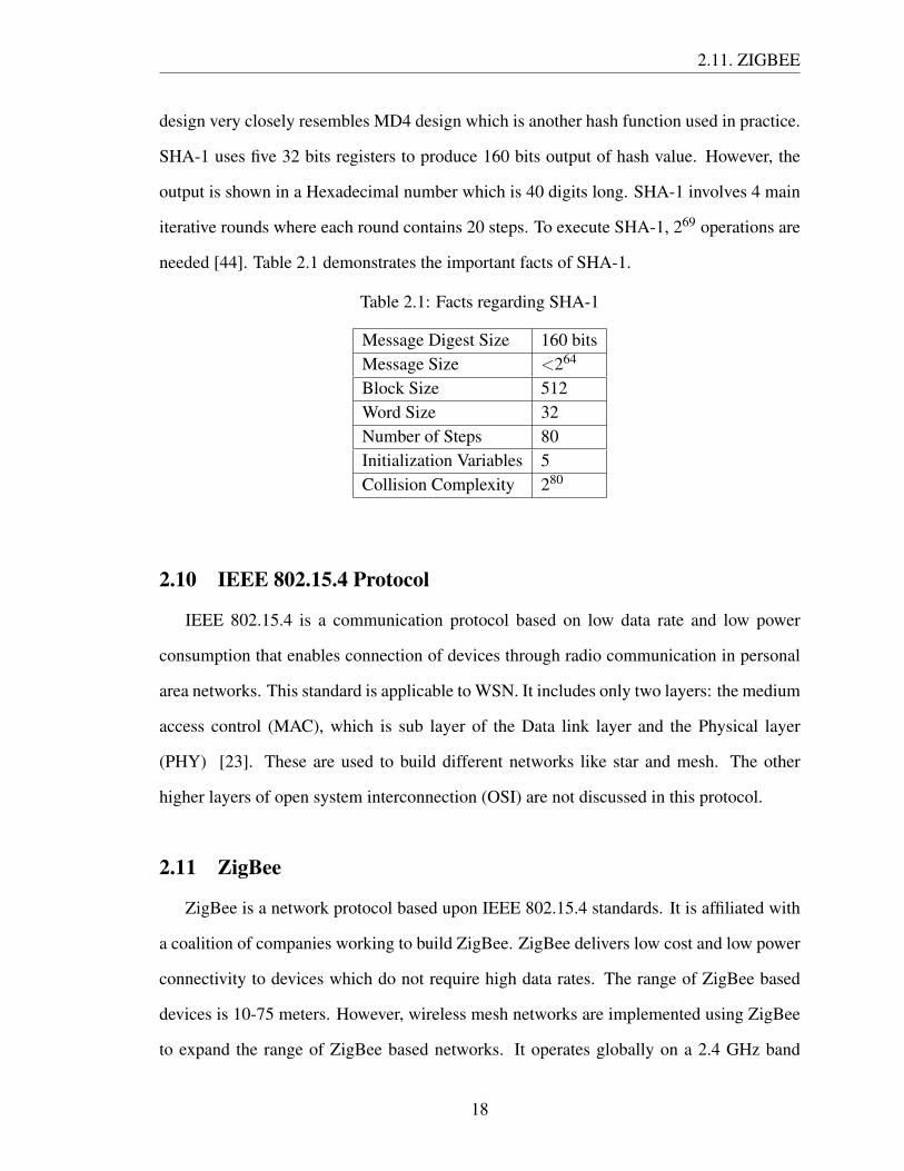
design very closely resembles MD4 design which is another hash function used in practice.
SHA-1 uses five 32 bits registers to produce 160 bits output of hash value. However, the
output is shown in a Hexadecimal number which is 40 digits long. SHA-1 involves 4 main
iterative rounds where each round contains 20 steps. To execute SHA-1, 269 operations are
needed [44]. Table 2.1 demonstrates the important facts of SHA-1.
Table 2.1: Facts regarding SHA-1
Message Digest Size 160 bitsMessage Size <264
Block Size 512Word Size 32Number of Steps 80Initialization Variables 5Collision Complexity 280
2.10 IEEE 802.15.4 Protocol
IEEE 802.15.4 is a communication protocol based on low data rate and low power
consumption that enables connection of devices through radio communication in personal
area networks. This standard is applicable to WSN. It includes only two layers: the medium
access control (MAC), which is sub layer of the Data link layer and the Physical layer
(PHY) [23]. These are used to build different networks like star and mesh. The other
higher layers of open system interconnection (OSI) are not discussed in this protocol.
2.11 ZigBee
ZigBee is a network protocol based upon IEEE 802.15.4 standards. It is affiliated with
a coalition of companies working to build ZigBee. ZigBee delivers low cost and low power
connectivity to devices which do not require high data rates. The range of ZigBee based
devices is 10-75 meters. However, wireless mesh networks are implemented using ZigBee
to expand the range of ZigBee based networks. It operates globally on a 2.4 GHz band
18

2.11. ZIGBEE
where the data transfer rate is 250 kbps [23].
Application
API
Security
NetworkStar/Mesh
MAC
PHY
2.4 GHz
Customer
ZigBee Alliance
IEEE 802.15.4
Figure 2.6: The ZigBee network architecture [35]
The ZigBee protocol is comprised of a coordinator, router and an end node. All these
three types of nodes have individual functions.
Figure 2.7: The ZigBe network [10]
The coordinator is the prime type of node in the network, with the ability to store infor-
mation and keys. Its main function is to manage the network; each network requires only
one coordinator. The router acts as an intermediate node in the pathway of data transmis-
19

2.12. DIGIMESH NETWORK
sion. The end device communicates with the parent devices, like router and coordinator,
and it is unable to relay data from other devices. It is low powered and low cost equipment.
2.12 DigiMesh Network
DigiMesh is a homogenous network of sensor nodes which are battery powered, inter-
changeable and capable of acting as a router. The DigiMesh offers the advantage of simple,
reliable and flexible networking. At the same time, it supports easy expansion of a network
and convenient replacement of the acting routers when they are damaged [10].
To minimize power requirements, a node is allowed to sleep when its functioning is
not required. In ZigBee network, only the end devices are permitted to sleep, whereas the
introduction of DigiMesh allows all the nodes to sleep. Therefore, the DigiMesh is more
power effective as compared to the ZigBee.
Figure 2.8: The DigiMesh network [10]
20

Chapter 3
Related Contributions and Motivation
This chapter provides the objective and motivation behind this research. There are a number
of research studies going on in the field of security of WSN. However, some of the important
research, which acts as the motivation and guidance behind my thesis is described in the
following section.
According to Lian et al. [33], the ZigBee network is noise free which has allowed Zig-
Bee to be established as the best wireless network technology for low power consumping
applications. It is one of the reasons for an increase research in the field of WSN based on
ZigBee technology. In this field the researchers use two approaches towards research: one
is simulation and the other is practical implementation. During practical implementation,
researchers use different sensor nodes to test their results. In previous studies [17] [40] [20],
the authors showed and compared their work on TelosB and MICAz sensor motes. A sensor
mote can be defined as a sensor node capable of processing and gathering sensor informa-
tion. TelosB and MICAz are very popular sensor motes for deploying WSN. However, they
lack the reconfigurability property.
Lian et al. [33] did their experiment on Arduino to deploy hand written word based
authentication for ZigBee. They presented a novel idea which incorporates ZigBee and Wi-
Fi to overcome the shortcomings of existing network technology. In their research, they did
not highlight security measures and the scrawled signature possessed some difficulties in
the verification of indentity. Baraka et al. [16] proposed a framework to remotely control a
home automation system. They used Arduino as a hardware to implement the design. They
21
3. RELATED CONTRIBUTIONS AND MOTIVATION
claimed their design was cost effective as well as energy efficient. A study of sensor cloud
system is outlined by Chandra et al. [19]. They also showed inclusion of an Arduino based
sensor network to read the cloud data. However, security consideration was absent in these
two frameworks [16] [19]. An experiment was done on Arduino [14] to test the outcome of
cryptographic function hash MD5 on an 8 bit microcontroller with 100% accuracy. Another
experiment was done on Arduino [13] to test public key cryptography RSA. Qasem et al.
[13] proposed and designed a microcontroller based RSA. They tested their design with 32
bit key size. Both these works [14] [13] implemented the algorithm on hardware. However,
they did not deal with real life data. In this section, it is observed that not many real life
implementations of WSN are done with Arduino.
The next section focuses on the security deployed in a WSN, and the problems and
threats associated with the existing proposals. During the time of deploying expensive
security measures, the fact of resource-constrained nodes demands consideration.
RSA and elliptic curve cryptography are widely used in public key cryptography. Ac-
cording to some researchers, due to the limitations of the sensor nodes, these two techniques
may place a heavy burden on the network. In spite of this, Gura et al. [25] and Watro et
al. [48] tested public key cryptography in resource constrained WSN. Gura et al. [25] de-
picted that, when ECC and RSA are compared they both are capable of working on an
8 bit CPU. However, the performance of ECC was better than RSA when small devices
were considered. Watro et al. [48] suggested TinyPK, a public key cryptography for in-
corporating security in WSN. This approach tested one MICA2 sensor node in the TinyOS
environment. The authentication and key agreement between two sensor networks is per-
mitted in this protocol without allowing any rekeying among the nodes.
Minisec [36] was implemented on a Telos mote platform. It provides high level security
while consuming less energy. An encryption key is stored in the sensor node in Minisec
but the actual technique for this has not yet been revealed. There is still an opportunity to
upgrade Minisec by improving the key management strategy.
22

3. RELATED CONTRIBUTIONS AND MOTIVATION
Karlof et al. [31] implemented an efficient link layer encryption protocol for WSN
called TinySec which is less energy and memory consuming. In this design a network
key was loaded before the network formation. One of the major drawbacks is, it does not
prevent reply attacks. They mentioned in their design that adding a counter to monitor data
packets might impose heavy burden on the sensor nodes memory. Therefore, they did not
include reply attack prevention in their design.
Liu et al. [34] presented a faster and more energy efficient public key cryptography
algorithm for WSN, named TinyECC, but some factors concerned with the patent have
limited its use.
SPINS [38], was developed by Perrig et al. which is a combination of two protocols,
SNEP and Tesla. A master key shared with the base station is the mainstay of security in
this protocol. Nevertheless, by compromising that master key, the intruders could decrypt
all information.
Though public key cryptography is an option for network security, it is costlier to im-
plement. In a study [47], Wang et al. studied and found that this public key cryptography
takes longer time to perform encryption and decryption which opens the door for the at-
tackers to execute denial of service attacks on the node. Furthermore, they discovered that
this technique consumes more energy in providing effective security. On the other hand,
they tested the symmetric cryptography algorithm on an Atmel ATmega128 processor and
revealed that this algorithm is much faster and more energy efficient when compared to the
public key algorithm. They also mentioned that, although symmetric key cryptography is
preferable to public key cryptography, it also has some limitations. There is no methodical
key changing option in practice which invites more research on flexible rekeying meth-
ods. Herrera et al. [26] pointed out a vital limitation of symmetric key based cryptography;
they said a single node tampering in symmetric key design becomes a threat to the whole
network. As a result, all master keys need to be pre installed in the sensor nodes again.
Nilsson et al. [37] presented asymmetric key management for the wireless process con-
23

3. RELATED CONTRIBUTIONS AND MOTIVATION
trol environment. In their design, they proposed a key changing methodology of sensor
nodes after a certain period of time. Their main intention was to design and verify the
framework. They did not address the resource constraints of the sensor node and their de-
sign was not practically implemented. Their encryption and decryption technique operated
via five symmetric and one public key. This results in adding many computational over-
heads like memory and communication. Establishing rekeying in this protocol requires
three messages.
Hu et al. [27] designed and implemented a sensor node which incorporates a RSA public
key and an XTEA symmetric key. They analyzed the performance in terms of computation
time, memory size, energy and cost. Nevertheless, the procedure of forming the rekeying
key was not highlighted. In addition, the total computational time and energy requirement
is significantly high.
Herrera et al. [26] published a paper which focused on key distribution in WSN. They
designed and implemented symmetric key distribution among sensor nodes using public
key cryptography. Additionally, they did not store the master key in the sensor nodes before
network establishment. They claimed their design as energy efficient as well as scalable.
They showed the result of their architecture in terms of execution time and energy. Gen-
eration of a new key involves six steps which are quite expensive for resource constrained
WSN. Their design also sends the new key over the network which is prone to attack by the
eavesdroppers. They did not mention any protection against attacks on WSN.
In this section, the research based on ZigBee protocol using Arduino and XBee incor-
porating symmetric key cryptography is reviewed. Pu and Chung [41] proposed a group
of key update methods for RC4 use in WSN, and implemented in Telos platform. Aziz et
al. [15] presented a wireless system using XBee to monitor and process the temperature
and humidity data a in tissue culture laboratory, but did not mention the security services
in their proposal. Kukkurainen et al. [32] depicted message encryption and message au-
thentication code based on the RC5 block cipher in a KILAVI sensor network platform.
24

3. RELATED CONTRIBUTIONS AND MOTIVATION
KILAVI is an open platform for deploying low data rate and low power consuming ap-
plications [32]. Dickerson et al. [21] proposed an RC4 based encrypted sensor network
and tested it in Mica2 network sensors with an Atmega128 microcontroller. They also
compared the performance between RC4 and RC5. Hyncica et al. [28] tested the XBee
performance in a small office environment and presented some important features related
to XBee communication.
All of the above mentioned research is centred on choosing the appropriate sensor de-
vice and imposing security in the network. After analyzing the background research it can
be concluded that symmetric key cryptography is more suitable for WSN than public key
cryptography because the provision for changing the keys makes it more robust. In pre-
vious research [26], [37], [27], the authors described rekeying procedure in WSN. In my
design, the shortcomings of the previously stated rekeying methods are mitigated. Accord-
ing to Nilsson et al. [37], five cryptographic keys were required to accomplish their design,
whereas in my design only two cryptographic keys are used to confer the network security.
Hu et al. [27] practically implemented their framework but did not discuss the formation of
a new key. In my proposed architecture a 40 bytes long new key is generated using hash
functions. Herrera et al. [26] used six steps to create a new key which is sent over the net-
work by the sensor nodes and receiver. On the other hand, the proposed design needs only
two steps for building a new key and there is no need to send the keys over the network. All
three of the above mentioned studies only portrayed key distribution mechanisms without
shedding any light on data sending procedure. My proposed framework shows key distri-
bution, as well as data sending, which ensures data authentication and integrity with its real
life implementation.
25

Chapter 4
Proposed Framework Design
This chapter highlights the details of my proposed framework design. It also includes how
my design achieved security features and prevented attacks.
In this thesis, I have proposed a new rekeying based security protocol for WSN. This
scheme provides confidentiality and authentication of sensor data. The notations used in
this protocol are described in Table 4.1.
Table 4.1: Notation used in rekeying framework
Symbol Description
N1,N2.....Nn Sensor Nodes
R Receiver/Base Station
Top One time password based on system time
Mk Initial Symmetric key between receiver and sensor nodes
NMk Unique new symmetric key for every sensor shared with receiver
Ek( ) Encryption operation executed by the sensor nodes
Dk( ) Decryption operation executed by the receiver
Hash( ) Operation to create new key
H ( ) Generate HMAC for data verification
The framework for rekeying is shown in Figure 4.1.
At the time of initiation, the sensor nodes are loaded with the initial master key and the
receiver also possesses the same key. Rekeying can be instituted in the nodes periodically.
26

4. PROPOSED FRAMEWORK DESIGN
Figure 4.1: Rekeying and data transfer between sensor node and receiver
Each node containes a software based real time clock (RTC) to generate a one time pass-
word. To protect against reply attacks, each and every rekeying initiation is accompanied
with this one-time password. This password is a randomly generated number depending
upon the real time clock of that particular system. Here F () is a function which takes the
system time as input and produces a one time password as output.
One time password (Top) = F (system-time)
The system time is based on the current date and time, so the password changes after
using it once. As previously mentioned, this one time password protects against reply
attacks as well as forfends an attacker to reply to old messages which is a fundamental
requirement for the rekeying operation in proposed framework.
This unique password is encrypted with an initial master key and is sent to the receiver
along with a signature. This signature is a hash message authentication code (HMAC). The
receiver decrypts the password, retrieves that exclusive password and verifies the signature.
27

4.1. SECURITY ISSUES ATTAINED BY THE DESIGN
To perform the encryption operation, stream cipher based encryption RC4 is used. The
new master key is formed in both the sensor nodes and in the receiver using a one way hash
function from the initial master key and the one-time password. Following this, the receiver
acknowledges to the sensor nodes that a new master key has been created. To address the
requirement of not reusing a key more than once, each produced key is distinct. The new
master key is the product of a hash function h ( ) based on SHA-1. The new master key is
40 bytes long. It is produced using the following formula:
New master key NMK = h (Top ‖ MK)
When the new master key is generated, the sensor nodes encrypt sensor data using this
key and also calculate a signature using a cryptographic hash. The encrypted data and
signature are then transmitted to the receiver side.
As soon as the receiver receives the encrypted data and signature, it uses the new master
key to decrypt the sensor data and this is followed by the formation of a signature. The
new signature is compared with the received signature and verified. Finally, if everything
is authenticated, the data is displayed on the monitor. The signature is generated using the
following function on both sides. Here HMAC is the message digest of hash function based
on the secret key and input.
Signature= HMACNMK(”Sensor Data”)
4.1 Security Issues Attained by the Design
My proposed framework achieved the following security issues:
4.1.1 Confidentiality:
In my design, symmetric key cryptography RC4 is used to encrypt a new key generation
session as well as during data transmission. As data is encrypted, it is protected from the
intruders and confidentiality is ensured.
28

4.2. ATTACK PREVENTION
4.1.2 Data integrity and authenticity:
The data should not be altered or modified during transmission known as data integrity,
and to confirm that the data is from a genuine sender is termed data authenticity. The
incorporation of HMAC safeguards both data authenticity and integrity. Cryptographic
hash SHA-1 is used to produce HMAC to attain both data integrity and authenticity.
4.1.3 Forward and backward secrecy:
When the attackers compromise a current key, they should not gain access to either the
preceding messages encrypted with the former keys or the upcoming messages encrypted
with the onward keys. These are referred to respectively as backward and forward secrecy.
To attain forward and backward secrecy, the use of the same key for a long period of time
is avoided. Instead, there is an option for changing that key according to the requirements
of the application.
4.2 Attack Prevention
My recommended system prevented the following attacks:
4.2.1 Man in the middle attack:
In the proposed framework, a master key is used at first and later on there is a provi-
sion for changing the master key so that the communicated data is encrypted at all times.
This approach guarantees that no attackers can interfere in the middle pretending to be an
authentic node.
4.2.2 Reply attack:
The system can avoid reply attacks on messages by means of a method generating a
unique number capable of detecting identical successive messages. Each and every commu-
nication in my designed framework is accompanied by a one-time password. This enables
the sender and the receiver to detect and reject replayed messages.
29

4.2. ATTACK PREVENTION
4.2.3 Tampering:
The sensor nodes in the WSN are not fully protected against external attacks. The
attacker may compromise a sensor node and steal cryptographic information. This thesis
highlights this fact and how to resist spreading attacks over all the sensor nodes. Therefore,
the design goal is to protect other nodes if one of the nodes is compromised by the attackers.
As rekeying is done periodically and different keys are used for different sensor nodes’
communication, compromising a sensor node will not compromise the whole network. As
a result, the attackers cannot decrypt information which is intended for the other nodes.
4.2.4 Sybil attack and hello flood attack:
In a Sybil attack, an outsider can act as an internal node. On the other hand, attackers
try to authenticate themshelves by broadcasting hello messages. However, the system can
prevent both of these attacks because every communication is established using a crypto-
graphic operation and HMAC. This makes it difficult for an outsider to act as an insider. As
there is an unique ID in the node, and communication is established using encryption and
HMAC, the authentic node does not respond to other hello flood messages.
30

Chapter 5
Hardware Component
This chapter discusses the hardware which was used in my experiment. This chapter also
includes some of the related sensor motes which are available in the market.
5.1 Arduino
A group of single board microcontrollers simplifying the establishment of interactive
objects or environment are called Arduino. This hardware is comprised of an open source
hardware board containing an 8-bit Atmel AVR microcontroller or a 32-bit Atmel ARM
microcontroller. The most up to date models are also equipped with a USB interface includ-
ing six analogue and fourteen digital pins. The users are allowed to connect the CPU with
various interchangeable add on shields by using the property of Arduino being a standard
connector. Most of the Arduinos deploy megaAVR series of chips with a 5 volt regulator
and a 16 MHz oscillator. Unlike other devices which need an external programmer, the
Arduino microcontroller along with the boot loader makes the uploading of programs on
chip flash memory easier and convenient [2].
5.2 Arduino Uno
The Arduino Uno refers to a microcontroller board consisting of 14 digital input/output
pins, 6 analogue inputs, a 16 MHz ceramic resonator, USB connection, power jack, an ICSP
header and a reset button. This board, based upon ATmega328, can work independently
when connected to a computer via USB or powered with an AC-to-DC adaptor or a battery.
31

5.3. ARDUINO XBEE SHIELD
Figure 5.1: Arduino UNO [3]
The board has a power jack which is connected to the adaptor by plugging a 2.1 mm center
positive plug or the leads from the battery are attached with the Gnd and Vin pin headers.
The major power pins of the board are VIN, 5V, 3V3, GND, IOREF and the optimum power
range for proper working is 7 to 12 volts. The ATmega328 has a memory capacity of 32
KB with 2 KB SRAM and 1 KB EEPROM.
Each of the 14 digital pins in the Uno functions at 5 volts, can provide or receive a
maximum of 50 mA, has an internal resistance of 20-50 kOhms and is capable of work-
ing as both input or output by utilizing pinMode, digitalWrite, and digitalRead functions.
However, some pins can uniquely act as Serial, External Interrupts, PWM, SPI, LED, TWI,
AREF or reset. The Arduino Uno has an excellent communication facility for connecting
with computers, other Arduinos or microcontrollers. The ATmega328 has a provision for
serial communication which materialize as a virtual com port to software on the computer.
Arduino Uno uses Arduino sketch for programming. The ATmega328 is pre equipped with
a boot loader for uploading the code without any external hardware or the device can also
be programmed through ICSP escaping the boot loader [3].
32

5.4. XBEE
5.3 Arduino XBee Shield
The XBee shield, based on the XBee module from Maxstream and constructed in as-
sociation with Libelium, is a device through which the Arduino board can communicate
wirelessly using ZigBee. This has the capability to communicate up to 100 feet indoor or
300 feet outdoor. The XBee shield can be configured for a wide range of broadcast and
mesh networking options and also can work in command mode. This device has the pro-
vision for breaking each of XBees pins to a through hole solder pad. It contains analogue
inputs covered with the shield and female pin headers for the use of digital pin 2 to 7. It
has two small, removable plastic sleeves for fitting onto two of the three pins labeled XBee/
USB, which are known as jumpers. The serial communication between the XBees micro-
controller and FTDI USB-to-serial chip on Arduino board is ascertained by these jumpers
[4].
Figure 5.2: Arduino XBee Shield [4]
5.4 XBee
XBee is a group of radio modules from Digi International. It was introduced in 2005
and is based on point-to-point and star communications. The working requirements of the
XBee radios are power, data in and data out, sleep and reset mode. Programmable XBee,
33

5.5. XBEE EXPLORER USB
Figure 5.3: XBee [11]
which is a special version, also has a built in onboard processor for the users. XBee radios
are capable of supporting a huge range of radio frequencies like 2.4 GHz or 902 - 928 MHz
or 865 - 868 MHz. The XBee radios are available in two hardware footprints: through hole
with 20 pin sockets and 37 pads surface mount.
The latter is compatible with both high and low volume deployments and is also cost-
effective. The XBee is effective at working in both transparent data mode and application
programming interface mode. Data received in the DIN pin is broadcasted to the receiver
radio unmodified in transparent data mode, whereas in API mode the data is wrapped into
packets for addressing, parameter setting and delivery feedback. XBee modules are ap-
propriate for a variety of network architectures including ZigBee, 802.15.4, and Wi-Fi.
Digimesh, a protocol from Digi has decreased the complexity of ZigBee protocol remark-
ably [11].
5.5 XBee Explorer USB
This is a serial based unit for the XBee line which is convenient to use with all XBee
modules and supports Wi-Fi bee and Bluetooth bee. When the unit is plugged into the
XBee explorer and attached to a mini USB cable, it is possible to gain access to serial
34

5.6. TEMPERATURE SENSOR TMP36
Figure 5.4: XBee with explorer [12]
and programming pins of XBee unit. This board is configured with an FT231X USB to
serial converter for translating data between the computer and the XBee, a reset button and
a voltage regulator to supply ample power. The device is also equipped with four LED
indicators for pointing out the power status, data transmission or receiving, signal strength
of data reception and association. These LED indicators are named as received signal
strength indicator (RSSI), Power (PWR), Transmitting (TXD), Receiving (RXD). The use
of a USB adaptor board for the XBee wireless module allows effective communication
between PC to PC or PC to robot and can modify the configuration of an XBee device
using PC through XCTU software. Moreover, the device can act as Communication Device
Class of USB family and gives the opportunity to use the USB port as a normal serial port.
The board can divide each of the XBees I/O pins to a pair of breadboard compatible headers
allowing efficient use of the wide functionality of XBee [12].
5.6 Temperature Sensor TMP36
The TMP36 is a precision centigrade temperature sensor which is low voltage and the
voltage output is linearly proportional to the celcius temperature. It is user friendly and
does not require any external calibration for its accuracy. The voltage input for this sensor
35

5.7. RELATED SENSOR MOTES
is typically 2.7 to 5.5 VDC and the output voltage can be converted to temperature by using
the scale factor of 10 mV/◦C. The functioning range for this sensor is -40◦C to + 125◦C
with an accuracy of 2◦C over temperature and 0.5◦C linearity [7].
Figure 5.5: Temperature sensor [7]
5.7 Related Sensor Motes
5.7.1 TelosB:
The University of California at Berkley first introduces TelosB for performing research
work in sensor network. This equipment consists of 16 bit, 8MHz TI MSP430 microcon-
troller with 10kB RAM, 48 KB flash memory and 16 KB EEPROM. It has built in sensors
like light, temperature or humidity sensors. The indoor range for TelosB is 20 to 30 m
whereas the outdoor range is 75 to 100 m with the data rate of 250 kbps [46].
36

5.7. RELATED SENSOR MOTES
Figure 5.6: TelosB mote [46]
5.7.2 MicaZ:
MicaZ is based on 802.15.4 protocol consisting of microcontroller ATMEL ATMega
128L. The data rate for this device is 250 kbps [5].
Figure 5.7: MicaZ mote [5]
5.7.3 Waspmote:
Waspmote is a product of Libillium having microcontroller ATmega1281 and EEPROM
4 KB. The power requirement is around 0.7uA during the phase of hibernation [8].
37

5.7. RELATED SENSOR MOTES
Figure 5.8: Waspmote senor node [8]
5.7.4 Shimmer:
Shimmer is a sensor node which is principally built for the wireless body sensor net-
work, whose main utilization is in the health sector. An important property of shimmer is
that it can use Wi-Fi and Bluetooth simultaneously [6].
38

Chapter 6
Implementation of the ProposedFramework
This chapter will discuss the implementation of my proposed framework. My description
covers all the small details of system architecture processing and implementation. This
chapter focuses on circuit set up, hardware configuration, program implementation and
communication in a stepwise approach.
6.1 Architecture of the System
6.1.1 Circuit and Wiring:
Figure 6.1: Circuit wiring of Arduino, Breadboard and Sensor
39

6.2. SYSTEM PROGRAMMING PHASE
In my design, four sensor nodes equipped with temperature sensor were used to act
as the sender while a laptop was used as receiver to accomplish the task. On the receiver
end, an XBee was attached to the XBee shield connected with the COM port of a laptop.
The sensor node was composed of Arduino, Arduino XBee shield, XBee, breadboard and
temperature sensors. Wiring was used to connect the Arduino node with the sensors. The
wiring and circuit design is depicted in Figure 6.1.
6.2 System Programming Phase
6.2.1 Communication establishment:
Figure 6.2: Working sensor node and receiver end
The communication started with using the XBee in the proposed design architecture.
In the beginning of the experiment communication was made between two sensor nodes.
One of the key requirements for this step was to configure the XBee to communicate in the
ZigBee network. I used X-CTU software to configure the XBee. During the experiment,
all XBee were configured with the addresses along with PAN ID and baud rate. The PAN
ID and baud rate should be the same to make a communication in an XBee based ZigBee
network. Subsequently, the XBee was attached in the XBee Arduino shield. After that, a
program was written in a Arduino Sketch to transmit sample data between nodes. As the
two sensor nodes had the addresses and were in the same PAN, successful communication
40

6.2. SYSTEM PROGRAMMING PHASE
Figure 6.3: Simple communication between the sender and the receiver
establishment was achieved between the nodes.
The next step was to make a communication between the sensor nodes and the receiver
which was a laptop. Here, both XBee were configured according to the needs of the system.
As XBee was connected in the COM port of the laptop, a program was written to read the
COM port data and processed it accordingly with addresses to identify the sensor nodes
and data. During the time of the experiment, the program was set to read incoming bytes
and was designed to read appropriate bytes received on the XBee receiver node. The whole
program was written in Java to read and process COM port data. Consequently, the design
was verified with different sample data and parameters to check the stability of the network.
The significant finding of this phase lay within data reading from the COM port. Several
problems were encountered in reading the data at the receiver end and few data were lost
during reading. However, this problem was solved by introducing the byte counts in the
program.
41

6.2. SYSTEM PROGRAMMING PHASE
6.2.2 Replacing the old key and rekeying:
At the time of deployment, the sensor nodes and the receiver were loaded with a fixed
key. At the initial phase the sensor nodes changed the predefined key. To change the key,
a program was written and uploaded. The program was based on RTC (real time clock),
which generated a one-time password. This password is a truly random construct from real
time. Even after every second, the program generates a different password. Consequently,
this password was encrypted with an RC4 symmetric key encryption which was written in
Arduino Sketch, and it produced a ciphertext in Hexadecimal format. The initial key was
used to complete the operation and SHA-1 was used to generate a signature. The ciphertext
and signature were transmitted over the network. The receiver received the ciphertext and
signature, extracted the address of the sender and started processing on the receiver side.
A Java based program was written on the receiver side which decrypted the ciphertext
and verified the signature. The receiver also used the initial predefined key to decrypt the
ciphertext. Therefore, the receiver along with the sensor nodes were using cryptographic
hash SHA-1 to produce new keys based on the same one-time password. This new key was
40 bytes long. Both the sender and the receiver replaced their initial key with the new 40
bytes key. Finally, the receiver acknowledged to the sensor nodes that a rekey had been
formed. This key was used for further communication until the formation of a new key.
The fundamental goal of this phase was to create a new key. I surveyed to choose the
method for forming a new key. Finally, cryptographic hash function was picked to create
the new key. The main reason behind choosing hash function is the one-way property of
the hash function. On the receiver side and the sender side the same program was written
which produced a new key. The synchronization between the nodes was also accomplished.
When the sensor nodes began to operate, every node changed its key using the proposed
framework. Thus, the receiver has different symmetric keys for communication with dif-
ferent nodes which made it very hard for the eavesdroppers to break the security of the
network. For larger networks, the use of database to store different keys for different nodes
42

6.2. SYSTEM PROGRAMMING PHASE
Figure 6.4: Key establishment during experiment
is appropriate. The simplified version of this phase is portrayed in the Figure 6.4.
6.2.3 Data transfer between the sensor nodes and the receiver:
After changing the pre-installed key, the sensor nodes began to transmit data with the
new key. A program was written in the sensor nodes to read sensor data continuously.
Encryption algorithm RC4 and hash algorithm SHA-1 were executed in Arduino for en-
cryption as well as signature generation. Next, the data was encrypted with the new key
using RC4 encryption which produced a ciphertext. At the same time, hash function SHA-
1 was used to produce a signature of 20 bytes. The SHA-1 produces a 20 bytes signature
irrespective of the data size. Afterwards, the ciphertext, (for example, B3, CE) was trans-
mitted along with a hash value, like 4d134bc072212ace2df385dae143139da74ec0ef, over
the ZigBee network. Each ciphertext separated itself using a comma, and each hash value
separated itself using new line.
The receiver station received the ciphertext and signature and it split the ciphertext
and hash value in the early stage. Then, it processed both ciphertext and hash value on
the receiver side using the program. On the receiver side the RC4 program decrypted the
43

6.2. SYSTEM PROGRAMMING PHASE
received ciphertext, for example B3, CE, using the same new key shared between the sender
and the receiver. For instance, the receiver got 24 as an output after decryption. Then, the
receiver forwarded 24 to the SHA-1 function. The SHA-1 function generated the new
hash value based on the decrypted value, in this case 24. The new hash value was then
compared with the received hash value to check the authenticity and integrity of the received
messages. After verifying, the value was displayed or stored for further processing.
During the data transmission phase, the sensor nodes might change their keys. So, the
request was initiated from the sensor nodes and the same steps for key generation were
repeated until the keys were replaced with the latest key.
Figure 6.5: Data transfer between the sender and the receiver
At this stage, it was difficult to separate each and every ciphertext, as well as the hash
values. When the ciphertext was sent, it was received in the COM port as an individual value
instead of the original ciphertext. For example, if the original ciphertext was CE, the COM
port would receive it as the individual value C, and individual value E. Then individual
values were combined to extract the original ciphertext. Furthermore, identifying each and
every ciphertext was challenging as the data was arriving very fast (Example: 100 data in
per second). To manage the fast arriving data a code was written. The data transfer stage is
44

6.2. SYSTEM PROGRAMMING PHASE
illustrated in Figure 6.5.
6.2.4 Implementing the whole concept in Mesh network:
As XBee Series 1 was used in my experiment, it comes with the facility of an in built
firmware DigiMesh. This facility of XBee Series 1 was utilized to build mesh networking
in my experiment. The mesh networking protocol is very powerful in terms of flexibility
and scalability. It supports multiple points of failure recovery, as well as it is very easy to
add more nodes to the network. As there are multiple paths in the network, the chances of
losing data were very low.
The work began with configuring XBee Series1 in XCTU. The Digimesh networking
comes with the unique network identifier. So, each XBee was configured with a unique
network identifier and address. As in the proposed framework, communication was built
between the sender and the receiver. Thus, each sender was configured with the destination
address of the receiver. If the sender were out of the range of the receiver, the intermediate
node would act as a router to forward data to the appropriate destination.
After successful configuration of XBee Series 1, the proposed framework was tested
both in closed and open environments. In the closed environment it was hard to understand
the working capability of mesh networking. Therefore, I chose an open environment to
test the framework. For testing purposes, a sensor node was placed far from the receiver
and was checked in the graphical monitor that whether it received any data from a remote
node. The remote node was situated out of the range of the receiver node. To test the
DigiMesh functionality, another sensor node was placed in between the remote node and
the receiver. At this time, the middle node was acting as a router between the remote node
and the receiver. In the meantime, the middle node also sent data to the receiver. After that,
two more nodes were added which were distant from each other. Then, the functionality of
the network was checked again. The Mesh networking protocol is portrayed in Figure 6.6.
At the time of deploying the sensor nodes, problems arose regarding sending data by
45

6.2. SYSTEM PROGRAMMING PHASE
Figure 6.6: The whole concept in Digimesh
the sensor nodes. In the early stage of deployment, few data were coming to the receiver
from the selected node and few data were missing. There were two reasons behind this.
One was the obstacles in the route between the sender and the receiver. The other one
was the synchronization. It was observed that, if all the nodes start sending data at the
same time resulting in collision, it may lead to loss of data. In the Arduino Sketch, there
is a functionality of delay ( ) which was properly maintained in all of the sensor nodes.
This ensured collision free travel towards the network and, thus, confirmed stability and
synchronization of the network.
6.2.5 Graphical user interface on the receiver side:
Figure 6.7 is the working graphical user interface to monitor nodes. For better depiction
and understanding of GUI, a sample model with two nodes are represented and described.
In this figure, GUI is divided into four parts.
46

6.2. SYSTEM PROGRAMMING PHASE
Figure 6.7: The working graphical user interface
The upper part shows inbound traffic; all the traffic which was received in the receiver
end is shown in this portion. The lower left hand portion displays ciphers related to key
changes. That portion illustrates different ciphers received for different nodes. One impor-
tant thing to note is that a unique cipher was always received. The sender sent a one-time
random password which is reflected in the GUI. This side also shows that, after decryption
and processing, a new key was generated that is also unique for each node communication.
The 40 bytes long key was displayed and used for further processing. The middle portion
47

6.2. SYSTEM PROGRAMMING PHASE
and the right portion are almost identical. However, they are showing different data. At the
beginning, it decrypted temperature which is shown to be 26. The signature was generated
and verified based on temperature in these cases, and is shown in the GUI.
48

Chapter 7
Testing and Evaluation
In this chapter, the performance of my proposed framework is demonstrated in terms of
execution time, power, energy, latency and throughput. Every detail of the testing phase and
experiment was considered. I tested the performance of encryption and cryptographic hash
algorithm on my proposed architecture. This chapter also compares my testing outcomes
with previously conducted research.
7.1 Execution Time
In the testing phase the execution time was divided into two parts. One portion dealt
with the time taken by the sensor nodes and the second portion was the time consumed
by the receiver. Code was written, both on the sender and the receiver side, to measure
the execution time. In the sensor node, the Arduino UNO was loaded with a program
which measured the time consumption for each operation. The clock was started before the
operation, which recorded the starting time, while the clock was stopped after operation,
which recorded the ending time. After that, the measurement was taken by subtracting the
starting time from the ending time. The same procedure was followed on the receiver side.
For better performance, the time was calculated in nanoseconds and it was later converted
to milliseconds.
The sensor node spent 26 ms to initialize the key, 8.5 ms for encryption, 4.5 ms for
signature and 0.5 ms in sensor reading. Therefore, 39.5 ms time in total was needed from
sensor reading to cryptographic operation. In contrast, the receiver side needed 2.65 ms
49

7.1. EXECUTION TIME
time in total from generation of key to cryptographic operation, which included 0.35 ms
for key generation, 1.4 ms for decryption and 0.9 ms for signature. When considering tem-
perature reading, the offered architecture took about 42.15 ms for the sender and receiver
portions together. The transmission time for ZigBee DigiMesh varied based on the distance
of the node. In the testing phase, the nearest node took around 85-100 millisecond for 8
byes of data, whereas the farthest node took around 120-130ms, which made the total time
consumed approximately 120 millisecond for the closest node and 165 millisecond for the
farthest node. The computation time in the sensor node is depicted in Table 7.1, followed
by a pictorial demonstration in Figure 7.1
Table 7.1: Execution time for a sensor node
Operation Time (ms)Key initialization 26New rekey generation 4Encryption 8.5Decryption 8.7Signature 4.5Sensor data read 0.5
Figure 7.1: Execution time taken by a sensor node
The above figure displays the data of Table 7.1 where the different segments of the pie
chart show the execution time for different operations. The major portion of time was for
50

7.2. EXECUTION TIME FOR VARIABLE SIZE OF SENSOR DATA
the key initialization, which was around 50% of the total time followed by decryption and
encryption, which consumed around 17% and 16% of the total time respectively. The least
time consuming procedure was the sensor reading, which took only 1% of the total time.
7.2 Execution time for variable size of sensor data
7.2.1 Encryption:
The execution time of the encryption algorithm for diverse data size in sensor nodes is
plotted in the graph below. This graphical representation, in Figure 7.2, shows that, with the
increasing data size, the execution time also increased with the use of encryption algorithm.
The data range considered here was 8 to 128 bytes. For 8 and 16 bytes of data, the time
requirement increased very little: these required 10.2 ms and 11.64 ms respectively. When
the data size was increased from 16 to 32 bytes, the consumed time also increased steeply
from 11.64 to 62.48 ms. After that, this increasing pattern remained identical for both
64 and 128 bytes data. The 64 bytes data consumed 179.85 ms, and the 128 bytes data
deployed 427.08 ms in the sensor nodes with the encryption algorithm.
Figure 7.2: Execution time for different sizes of sensor data with encryption
51

7.3. CURRENT CONSUMPTION
7.2.2 Signature generation:
The linear diagram in Figure 7.3 depicts the execution time for signature generation of
a sensor node when dealing with different sizes of data ranging from 8 to 128 bytes. This
diagram reflects the hash algorithm effects for signature generation over variable data size.
It can be clarified from the figure that, when the data size varied between 8 and 32 bytes,
there was almost no change in execution time for signature. From data size of 32 to 128
bytes, there was a steep linear increase of execution time. For 32 bytes of data, the sensor
node deployed in 4.15 ms, whereas for 64 bytes, the time reached to 8.18 ms. After 64
bytes to 128 bytes, the pattern of increasing time remained unchanged, and 128 bytes of
data needed around 12.316 ms execution time in the sensor node for signature generation.
Figure 7.3: Execution time required by different sizes of sensor data for signature genera-tion
7.3 Current consumption
In the proposed design, the current consumption was measured by the multimeter. For
example, a code for signature generation was uploaded in Arduino Uno and then the cur-
rent consumption of this mote was measured using the multimeter. This procedure was
52

7.3. CURRENT CONSUMPTION
repeated for different operations. A library of the Arduino was used which helped Arduino
to consume less current. For sensor node operations the current consumption for diverse
functions ranged from 50-57 mA. Different processes needed a variable amount of current
which is clearly depicted in the Table 7.2.
Table 7.2: Current consumption by a sensor node
Operation Current consumption (mA)Key initialization 57New rekey generation 56Encryption 53Decryption 54Signature 55Sensor data read 50
In the experiment, the XBee Series 1 radio was used to transmit data over the DigiMesh
network. This radio consumed 50-60 mA of current resulting in a double of the current
consumption of the sensor nodes. The total current consumption of a sensor node after
introducing the radio is outlined in the Table 7.3.
Table 7.3: Current consumption by a sensor node including radio
Operation Current consumption (mA)Key initialization 117New rekey generation 116Encryption 113Decryption 114Signature 115Sensor read 110
The information from the table is represented with the help of a pie chart. The segments
of the pie chart demonstrate the percentage of the total current consumed by different op-
erations in the sensor nodes after introducing the radio. Figure 7.4 demonstrates that the
highest current utilization was for key initialization followed by rekey generation and sig-
nature, whereas the sensor reading needed the lowest current. Though there was some
53

7.4. ENERGY CONSUMPTION
Figure 7.4: Current consumption by a sensor node
difference in current consumption among the different procedures, unlike execution time,
the current consumption was almost identical for diverse operations.
7.4 Energy consumption
The energy E in joules (J) is calculated using the following formula [9]
E(J) = P(W )× t(s) (7.1)
So the formula can be written as
joules = watts× seconds (7.2)
Which is represented as
J =W × s (7.3)
mJ = J/1000 (7.4)
On the other hand, to calculate watts, the following formula is used [1]
E(Wh) = Q(mAh)×V(V )/1000 (7.5)
54

7.5. INTRODUCING POWER SAVING ON THE SENSOR NODE
So, the formula can be demonstrated as
watt−hours = milliampere−hours× volts/1000 (7.6)
Which is represented as
Wh = mAh×V/1000 (7.7)
The energy consumption for different sensor node operations are varied. This informa-
tion is mentioned in Table 7.4 below, followed by a visual demonstration in the pie chart in
Figure 7.5.
Table 7.4: Energy consumption by a sensor node
Operation Energy (mJ)Key initialization 15.21New rekey generation 2.32Encryption 4.80Decryption 4.96Signature 2.59Sensor data read 0.275
Figure 7.5: Energy consumption by a sensor node
55

7.5. INTRODUCING POWER SAVING ON THE SENSOR NODE
7.5 Introducing power saving on the sensor node
As previously discussed in chapter 2, the nodes in a DigiMesh network can act as sleep-
ing nodes at any time. To save power in the network, the radio was activated when needed
to send data over the network. It reduced around 60 mA of current consumption. In a
DigiMesh network, the sleeping and awakening cycle of XBee requires special attention.
The mechanism consists of both hardware and software part. Pin 9 of the XBee functions
as a control pin for the sleep request. To make the radio sleep, the pin is set to a high volt-
age, and to wake, the pin is set to a low voltage. On the other hand, when considering the
programming part, the sleep request is controlled by the Arduino. The nodes used in this
experiment consumed around 35 mA of current when both the micro-controller and radio
were in sleeping mode. When performing an operation on the micro-controller, the current
consumption increased to around 50-60 mA. The procedure used to put the XBee to sleep is
outlined in Figure 7.6. In the figure, a wire which passed the command for voltage variation
from the Arduino was connected from pin 9 of the XBee to digital pin 6 of Arduino.
Figure 7.6: Circuit design to sleep XBee radio
The following figure shows a comparison of current consumption of a sensor node be-
tween active mode and sleep mode.
56

7.6. COMPARISON WITH PREVIOUS WORKS
Figure 7.7: Comparison of current consumption with sleep mode on and sleep mode off
The following figure shows the comparison of the energy consumption of a sensor node
between active mode and sleep mode.
Figure 7.8: Comparison of energy consumption in sleep mode on and sleep mode off
57

7.6. COMPARISON WITH PREVIOUS WORKS
7.6 Comparison with previous works
This work is compared with previously conducted works in respect to execution time,
power and energy.
Herrera et al. [26] tested their proposed design on a CSIRO opal mote [29]. This opal
mote model consisted of an integrated TPM. The TPM has built in RSA. The authors used
RSA to encrypt data. They did not mention the key generation. They described the key
generation time. For signature generation and verification, they used cryptographic hash
SHA-1.
Hu et al. [27] evaluated their performance on TrustedFleck which is based on Atmel
AT97SC3203S TPM chip. They tested their performance based on RSA, TinyECC and
Xtea. However, they focused their results on RSA, as it has built in TPM. Like Herrera et
al. [26], SHA-1 was also used for signature generation and verification.
During their work, the researchers measured the performance of a single sensor node
in terms of key criteria. They uploaded the program and monitored a single sensor node
performance based on execution time, power and energy. In my experiment, the same
steps were conducted for testing and then the results of my work were compared with their
work. During comparison, the memory constraint was also considered for executing the
encryption algorithm.
7.6.1 Execution time:
The following bar diagram represents the comparison between my proposed design and
two other previous studies, in regards to execution time for generating a new key. For
key generation, the difference between my study and others was nominal, whereas in other
operations my framework performed better. For encryption and decryption, the testing
architecture took 8.5 and 8.7 ms. On the other hand, the design by Herrera et al. [26] needed
257 ms for encryption and 972 ms for decryption. When considering the design by Hu et
al. [27], it took 55ms and 750 ms for encryption and decryption respectively. The condition
58

7.6. COMPARISON WITH PREVIOUS WORKS
remained the same for signature and initialization. The testing protocol performed better,
and took 4.5 ms for signature and 26 ms for initialization. In contrast, Herrera et al’s. [26],
study utilized 305 ms for signature and 836 ms for initialization. Hu et al. [27], in their
study, did not mention initialization and their protocol employed 787 ms for signature,
which was more than the time consumed by my offered architecture.
Figure 7.9: Comparison of execution time with Herrera et al. [26] and Hu et al. [27]
7.6.2 Current consumption:
The current consumption between my study and the studies done by Herrera et al. [26]
and Hu et al. [27] is compared and graphed in a bar diagram. It shows that my design
consumed more current than the other two designs in almost all operations. The framework
by Herrera et al. [26] needed 70 mA for key generation, 80 mA for encryption, 80 mA
for decryption, 80 mA for signature and 60 mA for initialization. When considering my
protocol, the figures were 116 mA for key generation, 113 mA for encryption, 114 mA for
decryption, 115 mA for signature and 117 mA for key initialization reflecting more current
consumption for the use of Arduino Uno and XBee radio. Hu et al. [27] did not discuss key
generation or initialization. However, their design needed 50.4 mA for encryption, 60.8
59

7.6. COMPARISON WITH PREVIOUS WORKS
mA for decryption, and 60.8 mA for signature generation. This is less than the current
consumed by the Herrera et al. [26] framework.
Figure 7.10: Comparison of current consumption with Herrera et al. [26] and Hu et al. [27]
7.6.3 Energy consumption:
The comparison of energy consumption between my designed protocols, and the archi-
tecture designed by Herrera et al. [26] and Hu et al. [27], is plotted in the Diagram 7.11.
It reveals a constant lower energy consumption in various operations of my design when
matched to the other two protocols. Among all the functions, the most energy was needed
for initialization, in my design, which was 15.21 mJ. Other energy consuming functions
included 2.32 mJ for key generation, 4.80 mJ for encryption, 4.96 mJ for decryption and
2.59 mJ for signature. As per the protocol of Herrera et al. [26], which was the most energy
consuming, 5.7 mJ was needed for key generation, 84.3 mJ for encryption, 326.59 mJ for
decryption, 323.57 mJ for signature, and 273.87 mJ for initialization, exceeding the amount
of energy used by my protocol. Again Hu et al. [27] limited their description to encryption,
decryption and signature but consumed less energy than the Herrera et al. [26] framework.
In that framework, 8.31 mJ was consumed for encryption, 136 mJ for decryption and 143
60

7.7. LATENCY
Figure 7.11: Comparison of energy consumption with Herrera et al. [26] and Hu et al. [27]
mJ for signature.
7.6.4 Explanation for low energy consumption:
In my experiment all the operations took significantly higher current which was in the
range of 110-117 mA. However, my design consumed considerably less energy which is in
the range of 0.275 mJ to 15.21 mJ for different operations. When comparing my work with
the work of Herrera et al. [26] and Hu et al. [27], the current consumption of their work
is less than my design which was in the range of 60-80 mA. Nevertheless, their operations
consumed significantly high amount of energy ranging from 5.7 to 326.59 mJ. All the op-
erations in my proposed design consumed less execution time and it is reflected in the low
energy consumption by my proposed design. One of the factor that could affect the result,
is the resistant of the device used. I did not consider the resistant in my experiment. The
previous works with which I compared my result, also did not address the resistant of their
device in their experiment.
61

7.7. LATENCY
7.7 Latency
Latency is the indicator of the time required for data transmission between the sender
and the receiver. Latency can be determined as a single trip latency or round trip latency. In
a single trip, one way transmission time is measured, whereas a round trip calculates two
way transmission time. At the time of the experiment, various data sizes were considered
for latency calculation. I tested the impact of different data sizes in several operations on
the sensor nodes. For calculating the latency time, the nearest and the farthest sensor nodes
from the receiver were considered.
The latency was measured with or without incorporating the DigiMesh network. While
encrypting varieties of data size value and generating their signature using hash function,
the latency was measured for different sensor nodes. During the time of experiment, the
receiver was equipped with an XBee connected to a laptop; on the other side, there were
four sensor nodes, two within range of the receiver and two out of range. As DigiMesh
was applied to the network, the nearest node could act as an intermediate router for data
transmission from the far nodes.
As my proposed framework was implemented, first the nearest node was considered for
data encryption and signature generation. In the process of encryption, around 100 sample
data were used and the average was taken. The same procedure was repeated for signature
generation. While performing encryption and signature generation for all other nodes, a
similar procedure was repeated. To accomplish these measurement, a program was written
on the receiver side which counted the bytes and extracted the time difference among the
consecutive data. In my experiment, the data usage was limited to 127 bytes as the XBee
based on the ZigBee network has the capability to transmit a maximum of 127 bytes of
data.
At the beginning of the experiment, the data was sent with encryption and also without
encryption from one of the sensor nodes. The time taken by the data to travel with or
without encryption is compared and diagrammed in the Figure 7.12.
62

7.7. LATENCY
Figure 7.12 shows that the time taken for data transmission was calculated with 8, 16,
32, 64 and 127 bytes of data. When the data was not encrypted, the time consumption was
less, whereas encrypted data took more time. It is noteworthy that the relationship between
increasing time and increasing data size was linear.
Figure 7.12: Latency calculation for encrypted and non encrypted data
In the second step of the latency experiment, signature generation time for a variety of
data size was calculated. It was observed that signature generation travel time was simi-
lar irrespective of the data size and remained in the range of 64-65 milliseconds which is
portrayed in Figure 7.13
Contrary to the previous experiment, the signature generation travel time showed a dif-
ferent trend. In the first experiment, latency was in increasing order, whereas for hash
operation the time difference was negligible. Any size of data took almost the same amount
of time. This phenomenon could be explained by the fact that hash operation creates the
same size of output for any given size of input data. That is the reason behind the negligible
travel time difference for signature generation using hash.
63

7.8. LATENCY CALCULATION IN DIGIMESH
Figure 7.13: Latency calculation for cryptographic hash
7.8 Latency calculation in Digimesh
The following Figure 7.14 is a diagramatic representation of the experiment setup for
testing in DigiMesh.
Figure 7.14: Experimental setup for testing in DigiMesh
In this stage of the experiment, latency was calculated using DigiMesh. The nearest
node was considered for this purpose, as before, and the results are plotted in the Diagram
7.15. It was seen that for RC4 encryption the latency time was showing an increasing
64

7.8. LATENCY CALCULATION IN DIGIMESH
pattern with increasing data size, whereas the hash value remained constant irrespective of
the data size; this supported previous experiments.
Figure 7.15: Latency experiment for the closest node
When comparing Figure 7.12 and 7.13 with Figure 7.15, it is noted that both for RC4
encryption and signature generation, the DigiMesh network consumed more time. For
example, for 8 bytes data without the DigiMesh network, the time consumed for the RC4
encryption was 48.34 millisecond, and for signature generation the time spent was 64.77
milliseconds. When DigiMesh was applied to the nearest node, the consumed times were
88.23 milliseconds for RC4 encryption and 192.47 milliseconds for hash generation.
Figure 7.16 shows the RC4 encryption time and signature generation time for the remote
node. The remote node consumed more time than the nearest node both for RC4 encryption
and hash generation. This was true for any size of data ranging from 8-127 bytes. However,
the trend of increasing latency time for RC4 encryption and similar signature generation
time with increased data size remained the same as for the nearest node.
65

7.9. THROUGHPUT
Figure 7.16: Latency experiment for the remote node
7.9 Throughput
Throughput is the amount of bits transferred over the network for a particular period
of time. Throughput depends on latency which is discussed in the previous section. The
equation to calculate throughput is [39].
T P =8×number o f bytes
total transmission time in milliseconds
Figure 7.17: Throughput for sensor data with and without encryption
66

7.10. THROUGHPUT IN DIGIMESH
The above figure shows throughput of sensor node data with encryption and without
encryption. The throughput increased linearly with the increase of data size. Moreover,
without encryption the throughput rate was better than with encryption.
In the meantime, hash function was applied in the sensor nodes. After introducing
hash function, the performance of the sensor nodes in terms of throughput was increased.
These result are depicted in Figure 7.18. From the figure, it is clear that the hash function
throughput also increased linearly with increased data size. As in the previous section, with
the increased data size, the hash operations performed better than the encryption operation
because of the output data size.
Figure 7.18: Throughput for sensor data with hash generating signature
7.10 Throughput in Digimesh
In Digimesh, the throughput was calculated for the nearest node and for the farthest
node. Figure 7.19 shows the throughput rate for encryption and hash generation in the
nearest node which was faster than the farthest node. For example, if the data size was 127
bytes, the throughput for encryption was 2.11 bits/milliseconds and for hash generation was
5.15 bits/milliseconds
67

7.10. THROUGHPUT IN DIGIMESH
Figure 7.19: Throughput for the nearest node in the DigiMesh network
Figure 7.20 reflects the throughput for the farthest node. Here it is observed that, for the
same data size encryption, throughput was 1.84 bits/milliseconds and signature generation
throughput was 4.04 bits/milliseconds. Both the figures clearly depict that the farthest node
was slower than the nearest node for any data size.
Figure 7.20: Throughput for the farthest node in the DigiMesh network
68

Chapter 8
Conclusion and Future works
8.1 Conclusion
WSN is gaining popularity in recent time which raises concerns about the security issues
of the network. In the background section, the different security attacks and their influences
over the network are mentioned. The details of the security attacks reflect that, node capture
attack is of prime consideration. The use of the same key and its use for a long time,
both leave a network vulnerable to a node capturing attack. Therefore, forming new keys
after a certain period and ensuring proper security in the keys improves the security of the
network. To fulfill this requirement, a new key formation and distribution protocol has been
presented that assures an efficient and secured end to end confidentiality of sensor data. This
scheme was based on the symmetric encryption technique. Following the implementation,
the security issues attained by my offered design are mentioned in the design and analysis
section. At the time of my key formation, a time based password was used with hash
function which also provided uniqueness to the key.
In my research after designing, the protocol was implemented in real life with the help of
an Arduino Uno microcontroller and XBee, along with sensors and a laptop as the receiver.
After successful implementation of the framework, the empirical performance of the design
was studied. The performance of this protocol was measured in respect to execution time,
energy consumption and power. The results were compared with previous works which
showed a better outcome. In conclusion, the secured key distribution and data reading has
provided a better security in the network with the reconfiguribility option, and has been
69

8.2. FUTURE WORKS
efficient regarding energy consumption and execution time.
At the end of the thesis, the following goals have been achieved:
1. Rekeying based key distribution protocol using symmetric encryption was proposed
and implemented.
2. The new 40 bytes of key was generated periodically.
3. The framework achieved data integrity, confidentiality, authenticity, and forward and
backward secrecy.
4. This design prevented some of the common attacks like man in the middle attack,
reply attack, tampering, sybil and hello flood attack.
5. The entire concept was implemented in reconfigurable Arduino UNO nodes with
XBee Series 1 radio. A DigiMesh network was formed to test the outcome of the sensor
network.
6. The performance of the proposed architecture was measured in terms of execution
time, energy utilization, current consumption, latency and throughput.
7. The outcome of the testing protocol was compared with previously implemented
research works and it has shown better result when considering execution time and energy
efficiency.
8.2 Future works
This protocol has been tested on a small network with four nodes. In the future, the
robustness of this protocol could be verified by introducing more nodes in the network.
The further extension of this protocol could be achieved by introducing Bluetooth in
the sensor side along with XBee and Arduino. As every smart phone is equipped with a
Bluetooth facility, the inclusion of Bluetooth would ensure expansion of the framework to
larger group of users.
After processing data in GUI, the data could be further sent over the Internet. This
would help to expand the applications of the proposed framework in the current trend of
70

8.2. FUTURE WORKS
WSN.
The response of the protocol could be tested with different real time attacks on the
sensor nodes. The system could be upgraded with a key which is more than 40 bytes long.
There is also a provision to upgrade the graphical user interface with more user flexibil-
ity and interactivity.
71

Bibliography
[1] Amp to Watt conversion description. http://www.rapidtables.com/convert/electric/mah-to-wh.htm. Accessed: 2015-02-20.
[2] Arduino description. http://arduino.cc/en/Main/Products. Accessed: 2015-02-20.
[3] Arduino UNO description. http://arduino.cc/en/Main/arduinoBoardUno. Ac-cessed: 2015-02-20.
[4] Arduino XBee Shield description. http://www.arduino.cc/en/Main/ArduinoXbeeShield. Accessed: 2015-02-20.
[5] Micaz description. http://www.memsic.com/userfiles/files/Datasheets/WSN/micaz_datasheet-t.pdf. Accessed: 2015-02-20.
[6] Shimmer description. http://www.shimmersensing.com/. Accessed: 2015-02-20.
[7] Temperature Sensor description. https://www.sparkfun.com/products/10988.Accessed: 2015-02-20.
[8] Waspmote description. http://www.libelium.com/products/waspmote/overview/. Accessed: 2015-02-20.
[9] Watt to Joule conversion description. http://www.rapidtables.com/convert/electric/Watt_to_Joule.htm. Accessed: 2015-02-20.
[10] Wireless mesh networking ZigBee vs DigiMesh. http://www.digi.com/pdf/wp_zigbeevsdigimesh.pdf. Accessed: 2015-02-20.
[11] XBee description. http://www.digi.com/xbee/. Accessed: 2015-02-20.
[12] XBee explorer USB description. https://www.sparkfun.com/products/11812.Accessed: 2015-02-20.
[13] Qasem Abu Al-Haija, Mashhoor Al Tarayrah, Hasan Al-Qadeeb, and AbdulmohsenAl-Lwaimi. A tiny RSA cryptosystem based on Arduino microcontroller useful forsmall scale networks. Procedia Computer Science, 34:639–646, 2014.
[14] Mochamad Vicky Ghani Aziz, Rifki Wijaya, Ary Setijadi Prihatmanto, and DiotraHenriyan. HASH MD5 function implementation at 8-bit microcontroller. In JointInternational Conference on Rural Information & Communication Technology andElectric-Vehicle Technology (rICT & ICeV-T), pages 1–5. IEEE, Nov 2013.
72

BIBLIOGRAPHY
[15] Noor Hafizah Abdul Aziz, Suzi Seroja Sarnin, Kama Azura Othman, Norfishah Wa-hab, Norzatina Misman, and Ahmad Tarmizi Hashim. Supervisory data acquisitionof temperature and humidity in oil palm tissue culture laboratory. In Second Inter-national Conference on Computational Intelligence, Modelling and Simulation (CIM-SiM), pages 470–475. IEEE, 2010.
[16] Kim Baraka, Marc Ghobril, Sami Malek, Rouwaida Kanj, and Ayman Kayssi. Lowcost Arduino/Android-based energy-efficient home automation system with smart taskscheduling. In Fifth International Conference on Computational Intelligence, Com-munication Systems and Networks (CICSyN), pages 296–301. IEEE, June 2013.
[17] Bastian Bloessl, Stefan Joerer, Fabian Mauroner, and Falko Dressler. Low-cost inter-ferer detection and classification using TelosB sensor motes. In Proceedings of the18th Annual International Conference on Mobile Computing and Networking, pages403–406. ACM, 2012.
[18] Seyit A Camtepe and Bulent Yener. Key distribution mechanisms for wireless sen-sor networks: a survey. Rensselaer Polytechnic Institute, Troy, New York, TechnicalReport, pages 05–07, 2005.
[19] Abel Avitesh Chandra, Yeonwoo Lee, Beom Mu Kim, Se Yeong Maeng, Sang HyeokPark, and Seong Ro Lee. Review on sensor cloud and its integration with Arduinobased sensor network. In International Conference on IT Convergence and Security(ICITCS), pages 1–4. IEEE, Dec 2013.
[20] Brendan Cody-Kenny, David Guerin, Desmond Ennis, Ricardo Simon Carbajo,Meriel Huggard, and Ciaran Mc Goldrick. Performance evaluation of the 6LoWPANprotocol on MICAz and TelosB motes. In Proceedings of the 4th ACM Workshopon Performance Monitoring and Measurement of Heterogeneous Wireless and WiredNetworks, pages 25–30. ACM, 2009.
[21] Damian Dickerson, Sung H Yoon, Jung H Kim, and Gi T Hur. Efficient RC4 basedencryption system for sensor network. Proc. SPIE,, 5778:819–823, 2005.
[22] Bruno Dutertre, Steven Cheung, and Joshua Levy. Lightweight key management inwireless sensor networks by leveraging initial trust. SRI-SDL-04-02, SRI Interna-tional, Technical Report, 2004.
[23] Sinem Coleri Ergen. Zigbee/ IEEE 802.15. 4 summary. UC Berkeley, September,10:17, 2004.
[24] Laurent Eschenauer and Virgil D Gligor. A key-management scheme for distributedsensor networks. In Proceedings of the 9th ACM Conference on Computer and Com-munications Security, pages 41–47. ACM, 2002.
[25] Nils Gura, Arun Patel, Arvinderpal Wander, Hans Eberle, and Sheueling ChangShantz. Comparing elliptic curve cryptography and RSA on 8-bit cpus. In Cryp-tographic Hardware and Embedded Systems-CHES 2004, pages 119–132. Springer,2004.
73

BIBLIOGRAPHY
[26] Adrian Herrera and Wen Hu. A key distribution protocol for wireless sensor networks.In Proceedings of the 2012 IEEE 37th Conference on Local Computer Networks (LCN2012), pages 140–143. IEEE Computer Society, 2012.
[27] Wen Hu, Hailun Tan, Peter Corke, Wen Chan Shih, and Sanjay Jha. Toward trustedwireless sensor networks. ACM Transactions on Sensor Networks (TOSN), 7(1):5:1–5:25, August 2010.
[28] O Hyncica, P Kacz, P Fiedler, Z Bradac, P Kucera, and R Vrba. The ZigBee ex-perience. In Proceedings of the 2nd International Symposium on Communications,Control, and Signal Processing. Citeseer, 2006.
[29] Raja Jurdak, Kevin Klues, Brano Kusy, Christian Richter, Koen Langendoen, andMichael Brunig. Opal: A multiradio platform for high throughput wireless sensornetworks. Embedded Systems Letters, IEEE, 3(4):121–124, 2011.
[30] Joseph M Kahn, Randy H Katz, and Kristofer SJ Pister. Next century challenges:mobile networking for smart dust. In Proceedings of the 5th Annual ACM/IEEE Inter-national Conference on Mobile Computing and Networking, pages 271–278. ACM,1999.
[31] Chris Karlof, Naveen Sastry, and David Wagner. TinySec: a link layer security archi-tecture for wireless sensor networks. In Proceedings of the 2nd International Confer-ence on Embedded Networked Sensor Systems, pages 162–175. ACM, 2004.
[32] Juha Kukkurainen, Mikael Soini, and Lauri Sydanheimo. RC5-based security in wire-less sensor networks: utilization and performance. WSEAS Transactions on Comput-ers, pages 1191–1200, 2010.
[33] Kuang-Yow Lian, Sung-Jung Hsiao, and Wen-Tsai Sung. Intelligent multi-sensorcontrol system based on innovative technology integration via ZigBee and Wi-Fi net-works. Journal of Network and Computer Applications, 36(2):756–767, 2013.
[34] An Liu and Peng Ning. TinyECC: A configurable library for elliptic curve cryp-tography in wireless sensor networks. In International Conference on InformationProcessing in Sensor Networks IPSN’08, pages 245–256. IEEE, 2008.
[35] Kun-Yung Lu. A plug-and-play data gathering system using ZigBee-based sensornetwork sensor network. Computers in Industry, 62(7):719–728, 2011.
[36] Mark Luk, Ghita Mezzour, Adrian Perrig, and Virgil Gligor. MiniSec: a secure sensornetwork communication architecture. In Proceedings of the 6th International Confer-ence on Information Processing in Sensor Networks, pages 479–488. ACM, 2007.
[37] Dennis K Nilsson, Tanya Roosta, Ulf Lindqvist, and Alfonso Valdes. Key manage-ment and secure software updates in wireless process control environments. In Pro-ceedings of the First ACM Conference on Wireless Network Security, pages 100–108.ACM, 2008.
74

8.2. FUTURE WORKS
[38] Adrian Perrig, Robert Szewczyk, JD Tygar, Victor Wen, and David E Culler. SPINS:Security protocols for sensor networks. Wireless Networks, 8(5):521–534, 2002.
[39] Rajeev Piyare and Seong-ro Lee. Performance analysis of XBee ZB module basedwireless sensor networks. International Journal of Scientific & Engineering Research,4(4):1615–1621, 2013.
[40] Aggeliki Prayati, Ch Antonopoulos, Tsenka Stoyanova, Christos Koulamas, andGeorge Papadopoulos. A modeling approach on the TelosB WSN platform powerconsumption. Journal of Systems and Software, 83(8):1355–1363, 2010.
[41] Chuan-Chin Pu and Wan-Young Chung. Group key update method for improvingRC4 stream cipher in wireless sensor networks. In International Conference on Con-vergence Information Technology, pages 1366–1371. IEEE, 2007.
[42] Yi Qian, Kejie Lu, and David Tipper. A design for secure and survivable wirelesssensor networks. Wireless Communications, IEEE, 14(5):30–37, 2007.
[43] An-Ni Shen, Song Guo, and Hung-Yu Chien. An efficient and scalable key distributionmechanism for hierarchical wireless sensor networks. In Sarnoff Symposium, 2009.SARNOFF’09. IEEE, pages 1–5. IEEE, 2009.
[44] W Stilings. Cryptography and network security principles and practices. Prentice-Hall, 5th edition, 2011.
[45] Kuen Hung Tsoi, Kin-Hong Lee, and Philip Heng Wai Leong. A massively paral-lel rc4 key search engine. In Proceedings 10th Annual IEEE Symposium on Field-Programmable Custom Computing Machines, pages 13–21. IEEE, 2002.
[46] Haodong Wang and Qun Li. Efficient implementation of public key cryptosystems onMICAz and TelosB motes. College of William and Mary, Techical Report. WM-CS-2006, 7, 2006.
[47] Yong Wang, G. Attebury, and B. Ramamurthy. A survey of security issues in wirelesssensor networks. Commun. Surveys Tuts., 8(2):2–23, April 2006.
[48] Ronald Watro, Derrick Kong, Sue-fen Cuti, Charles Gardiner, Charles Lynn, and PeterKruus. TinyPK: securing sensor networks with public key technology. In Proceedingsof the 2nd ACM Workshop on Security of Ad Hoc and Sensor Networks, pages 59–64.ACM, 2004.
[49] Mark Weiser. The computer for the 21st century. Scientific American, 265(3):94–104,1991.
[50] Kai Xing, Shyaam Sundhar Rajamadam Srinivasan, Major Jose, Jiang Li, XiuzhenCheng, et al. Attacks and countermeasures in sensor networks: a survey. In NetworkSecurity, pages 251–272. Springer, 2010.
[51] Jennifer Yick, Biswanath Mukherjee, and Dipak Ghosal. Wireless sensor networksurvey. Computer Networks, 52(12):2292–2330, August 2008.
75