efficient implementation of real-valued fir filters on the...
TRANSCRIPT
Application ReportSPRA655 - April 2000
1
Efficient Implementation of Real-Valued FIR Filterson the TMS320C55x DSP
David M. Alter DSP Applications – Semiconductor Group
ABSTRACT
Real-valued digital finite impulse response (FIR) filters form the basis for numerous digitalsignal processing (DSP) applications. Efficient implementation of these filters on theTMS320C55xx DSP family requires specialized algorithm structuring that can takeadvantage of the dual on-chip hardware multiplier units. This application report presentsimplementations best suited for block FIR and single-sample FIR filters. Example assemblycode is also provided.
Contents
1 Introduction 2. . . . . . . . . . . . . . . . . . . . . . . . . . . . . . . . . . . . . . . . . . . . . . . . . . . . . . . . . . . . . . . . . . . . . . . . .
2 Block FIR Filter Implementation 2. . . . . . . . . . . . . . . . . . . . . . . . . . . . . . . . . . . . . . . . . . . . . . . . . . . . . . .
3 Single-Sample FIR Filter Implementation 3. . . . . . . . . . . . . . . . . . . . . . . . . . . . . . . . . . . . . . . . . . . . . .
4 Example Code Descriptions 5. . . . . . . . . . . . . . . . . . . . . . . . . . . . . . . . . . . . . . . . . . . . . . . . . . . . . . . . . . 4.1 General Information About Both Programs 5. . . . . . . . . . . . . . . . . . . . . . . . . . . . . . . . . . . . . . . . . . . 4.2 Block-FIR Filter Program Information 6. . . . . . . . . . . . . . . . . . . . . . . . . . . . . . . . . . . . . . . . . . . . . . . . 4.3 Single-Sample FIR Filter Program Information 6. . . . . . . . . . . . . . . . . . . . . . . . . . . . . . . . . . . . . . . .
5 Conclusion 7. . . . . . . . . . . . . . . . . . . . . . . . . . . . . . . . . . . . . . . . . . . . . . . . . . . . . . . . . . . . . . . . . . . . . . . . . .
Appendix A Block FIR Filter Program (Algebraic Syntax) 8. . . . . . . . . . . . . . . . . . . . . . . . . . . . . . . . . . Appendix B Block FIR Filter Program Mnemonic Syntax 11. . . . . . . . . . . . . . . . . . . . . . . . . . . . . . . . . . Appendix C Single-Sample FIR Filter Program (Algebraic Syntax) 14. . . . . . . . . . . . . . . . . . . . . . . . . Appendix D Single-Sample FIR Filter Program (Mnemonic Syntax) 19. . . . . . . . . . . . . . . . . . . . . . . . Appendix E Include File Containing Example Input Data 24. . . . . . . . . . . . . . . . . . . . . . . . . . . . . . . . . . Appendix F Output From Block FIR Filter Program 25. . . . . . . . . . . . . . . . . . . . . . . . . . . . . . . . . . . . . . . Appendix G Output From Single-Sample FIR Filter Program 26. . . . . . . . . . . . . . . . . . . . . . . . . . . . . .
List of Figures
Figure 1. Computation Groupings for a Block FIR (4-tap filter shown) 3. . . . . . . . . . . . . . . . . . . . . . . . . . . . Figure 2. Computation Groupings for a Single-Sample FIR with an Even Number of TAPS
(4-tap filter shown) 4. . . . . . . . . . . . . . . . . . . . . . . . . . . . . . . . . . . . . . . . . . . . . . . . . . . . . . . . . . . . . . . . Figure 3. Computation Groupings for a Single-Sample FIR with an Odd Number of TAPS
(5-tap filter shown) 5. . . . . . . . . . . . . . . . . . . . . . . . . . . . . . . . . . . . . . . . . . . . . . . . . . . . . . . . . . . . . . . .
TMS320C55xx is a trademark of Texas Instruments.

SPRA655
2 Efficient Implementation of Real-Valued FIR Filters on the TMS320C55x DSP
1 Introduction
Real-valued digital finite impulse response filters form the basis for numerous digital signalprocessing applications. The basic operation needed to implement a FIR filter is the multiply-and-accumulate (MAC) operation, an operation to which DSPs have traditionally excelled.Equation 1 shows a mathematical expression for the FIR filter.
y(k) ��N
i�0
ai x(k � i )
where k is the time step, y(k) is the filter output at time k, x(k–i) is the sampled input at time k–i,ai is filter coefficient i, and N is the order of the filter (i.e., the number of taps minus 1). For example,a four-tap (i.e., third-order) FIR filter can be explicitly written as
y(k) � a0 x(k) � a1 x(k � 1) � a2 x(k � 2) � a3 x(k � 3)
Since the C55xx DSP has two MAC units, one would expect the ability to perform two MACcomputations per DSP clock cycle. A brute-force approach to the four-tap filter in Equation 2would compute a0*x(k) and a1*x(k–1) on the first cycle, and a2*x(k–2) and a3*x(k–3) on thesecond cycle. With this approach, the computations require accessing four independent datavalues each processor cycle. However, the C55xx DSP has only three 16-bit-wide data buses,and therefore, one cannot just implement the algorithm in the brute-force manner suggested. Itis possible, however, to specially structure the filter implementation so that two MAC operationscan still be performed on a C55xx every clock cycle, thereby maximizing DSP performance. Thisapplication report presents the special FIR filter implementations necessary to maximizeperformance on the C55xx DSP family.
Implementation of a FIR filter may be classified into two types: single-sample and block. In thesingle-sample version, one input value arrives each sample period, with the FIR algorithmgenerating a single output value each sample period. The single-sample FIR must therefore run inrealtime. In the block FIR filter, all input data is available a priori. Therefore, the block FIR need notrun in realtime, but rather can process all input values as quickly (or as slowly as the case may be)as desired. Each of these two filter types requires different structuring for efficient implementation onthe C55xx DSP. The simpler case is the block FIR, which will be discussed first.
2 Block FIR Filter Implementation
The efficient implementation for block FIR filters involves computing two sequential filteriterations in parallel so that only a single coefficient, ai, is utilized by both MAC units. Figure 1depicts the computation grouping for a four-tap filter. Outputs y(k) and y(k–1) are computed inparallel. For the first term in each of these two rows, one MAC unit computes a0x(k), while thesecond MAC unit computes a0x(k–1). These two computations combined require only threedifferent values from memory, i.e., a0, x(k), and x(k–1). Proceeding to the second term in eachrow, a1x(k–1) and a1x(k–2) are computed similarly, and so on with the remaining terms. Afterfully computing the outputs y(k) and y(k–1), the next two outputs are computed, i.e., y(k–2) and y(k–3) in parallel, again beginning with the first two terms in each of these rows. In this way,DSP performance is maintained at two MAC operations per clock cycle.
C55x is a trademark of Texas Instruments.
(1)
(2)

SPRA655
3 Efficient Implementation of Real-Valued FIR Filters on the TMS320C55x DSP
Note that filters with either an even or odd number of taps are equally handled by this method.Further, not all the input data need be available in advance. Rather, only two new input samplesare required for each iteration through the algorithm, thereby producing two new output values.For example, suppose data values are arriving at regular (or irregular) intervals via the DSPserial port. After two such values arrive, the DSP could process them through the filter and thensend the two output samples on their way, for example transmit them out via the serial port. Thisgives a quasi real-time process, where the DSP essentially processes two input values everyother time a value arrives, and is free to perform other tasks when not processing input data.
y(k) = a1x(k–1)
a1x(k–2)
a2x(k–2)
a2x(k–3)
a3x(k–3)
a3x(k–4)
a0x(k–2)
a0x(k–3) a1x(k–4)
a2x(k–4)
a2x(k–5)
a3x(k–5)
a3x(k–6)
y(k–1) =
y(k–3) =
•••
y(k–2) =
•••
++ +
+
a0x(k)
a0x(k–1) + +
+ a1x(k–3) +
+
+
+ +
Figure 1. Computation Groupings for a Block FIR (4-tap filter shown)
3 Single-Sample FIR Filter Implementation
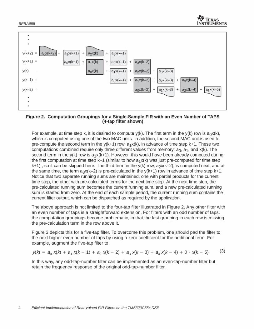
Single-sample FIR filtering requires real-time calculation. That is, one input value is receivedevery sample period, which in turn is used to compute one output value every sample period.The FIR implementation utilized for the block FIR will not work in a real-time applications, sinceat best, two output values are computed every other sample period. This is not realtime. Thesingle-sample FIR implementation presented here interlaces the calculations for the currentsample period with those of the next sample period in order to achieve a net performance of twoMAC operations per cycle. Figure 2 shows the needed computation groupings for a four-tapFIR filter. At any given time step, one multiplies and accumulates every other partial product inthe corresponding row, beginning with the first partial product in the row. In addition, one alsomultiplies and accumulates every other term in the next row (i.e., the row above the current row)in advance of that time step, beginning with the second partial product in the next row. In thisway, each row is fully computed over the course of two sample periods.
SPRA655
4 Efficient Implementation of Real-Valued FIR Filters on the TMS320C55x DSP
y(k+2) = a1x(k+1)
a1x(k)
a2x(k)
a2x(k–1)
a3x(k–1)
a3x(k–2)
a0x(k)
a0x(k–1) a1x(k–2)
a2x(k–2) a3x(k–3)
y(k+1) =
y(k–1) =
•••
y(k) =
++ +
+
a0x(k+2)
a0x(k+1) + +
+ a1x(k–1) +
+
+
+ +
•••
a0x(k–2)
a2x(k–3)
a1x(k–3)+
a3x(k–4)
a2x(k–4)+ a3x(k–5)+y(k–2) =
Figure 2. Computation Groupings for a Single-Sample FIR with an Even Number of TAPS(4-tap filter shown)
For example, at time step k, it is desired to compute y(k). The first term in the y(k) row is a0x(k),which is computed using one of the two MAC units. In addition, the second MAC unit is used topre-compute the second term in the y(k+1) row, a1x(k), in advance of time step k+1. These twocomputations combined require only three different values from memory: a0, a1, and x(k). Thesecond term in the y(k) row is a1x(k+1). However, this would have been already computed duringthe first computation at time step k–1 (similar to how a1x(k) was just pre-computed for time stepk+1) , so it can be skipped here. The third term in the y(k) row, a2x(k–2), is computed next, and atthe same time, the term a3x(k–2) is pre-calculated in the y(k+1) row in advance of time step k+1.Notice that two separate running sums are maintained, one with partial products for the currenttime step, the other with pre-calculated terms for the next time step. At the next time step, thepre-calculated running sum becomes the current running sum, and a new pre-calculated runningsum is started from zero. At the end of each sample period, the current running sum contains thecurrent filter output, which can be dispatched as required by the application.
The above approach is not limited to the four-tap filter illustrated in Figure 2. Any other filter withan even number of taps is a straightforward extension. For filters with an odd number of taps,the computation groupings become problematic, in that the last grouping in each row is missingthe pre-calculation term in the row above it.
Figure 3 depicts this for a five-tap filter. To overcome this problem, one should pad the filter tothe next higher even number of taps by using a zero coefficient for the additional term. Forexample, augment the five-tap filter to
y(k) � a0 x(k) � a1 x(k � 1) � a2 x(k � 2) � a3 x(k � 3) � a4 x(k � 4) � 0 � x(k � 5)
In this way, any odd-tap-number filter can be implemented as an even-tap-number filter butretain the frequency response of the original odd-tap-number filter.
(3)

SPRA655
5 Efficient Implementation of Real-Valued FIR Filters on the TMS320C55x DSP
y(k+2) = a1x(k+1)
a1x(k)
a2x(k)
a2x(k–1)
a3x(k–1)
a3x(k–2)
a0x(k)
a0x(k–1) a1x(k–2)
a2x(k–2) a3x(k–3)
a4x(k–3)y(k+1) =
y(k–3) =
•••
y(k) =
++ +
+
a0x(k+2)
a0x(k+1) + +
+ a1x(k–1) +
+
+
+ +
•••
a4x(k–2)
a0x(k–2)
a2x(k–3)
a1x(k–3)+
+
a3x(k–4)
a4x(k–4)
a2x(k–4)
+
+
a4x(k–5)
a3x(k–5)
+
+ a4x(k–6)+
incompletegroupings
Figure 3. Computation Groupings for a Single-Sample FIR with an Odd Number of TAPS(5-tap filter shown)
4 Example Code Descriptions
Assembly code programs are given in Appendices A through D for the block FIR filter and thesingle-sample FIR filter. Both algebraic and mnemonic assembly syntaxes are provided. Eachprogram runs stand-alone, and implements an identical 16-tap FIR low-pass filter. Theseprograms are intended to provide a general idea of how to efficiently implement both types ofFIR filters at the assembly code level. The user should tailor the basic code to meet his or herindividual program requirements. Information about the programs follows.
4.1 General Information About Both Programs
• The coefficients used for the 16-tap filter give a low-pass frequency response with unityD.C. gain, and a –3 dB cutoff frequency of 0.27ωs, where ωs is the sampling frequency.
• The coefficients shown are for a symmetric FIR filter (i.e., coefficient a0 is the same as a15 ,a1 is the same as a14 , and so forth). A symmetric filter is in no way a requirement for theseFIR algorithms. Symmetric coefficients just happen to have been used in these examples.Note that a symmetrical FIR filter could be effectively implemented using a brute-forcedual-MAC approach, since only three operands need to be fetched to compute two filtertaps. Note also that the C55xx processor has the firs() algebraic instruction (FIRSADDmnemonic instruction) that is specially designed to implement symmetrical FIR filters. Thefirs() instruction will not result in a lower kernel cycle count. The minimum number ofkernel cycles is N_TAPS/2, which is achieved using any of the three methods: firs() , abrute-force dual-MAC approach, or the approach presented in this report. However, firs()may result in fewer overhead cycles (i.e., pointer setup, context save and restore, etc.),especially in the single-sample filter case. Additionally, firs() may result in lower powerconsumption since it performs one multiplication and two additions for every two taps,whereas the other two methods perform two multiplications and one addition.
• Both programs are designed for Q15 fraction input data, output data, and coefficients.
• Both programs utilize the input data in the file DUALSINE.DAT (see Appendix E). The 199values are Q15 fractions that represent the linear superposition of two distinct sine waves. One

SPRA655
6 Efficient Implementation of Real-Valued FIR Filters on the TMS320C55x DSP
sine wave has a frequency of 0.0125ωs, and the second has a higher frequency of 0.25ωs,where ωs is the sampling frequency. The implemented 16-tap filter will essentially remove thehigher frequency sine wave, leaving only the lower frequency sine wave in the output data.
• Both programs have been assembled, linked, and simulated using C5000 Code ComposerStudio v1.19 (TMS320C55xx COFF Assembler v1.10 and TMS320C55xx COFF Linker v1.10).
4.2 Block-FIR Filter Program Information
• The block FIR filter routine is a self-contained program. As structured, it takes an array ofinput values located at data memory address x and processes them as a block into anoutput array that is located at address y.
• An incomplete table of interrupt vectors is provided. This table contains only the first threevectors (e.g., reset, nmi, and int2), of which only the reset vector is needed to run thisprogram stand-alone. Users should construct a complete interrupt vector table as requiredby their particular application.
• The filter kernel requires that three operands be fetched from memory each clock cycle: onefrom the coefficient array, and two from the input data array. In order to avoid memoryaccess conflicts, these arrays should be linked in memory to allow such access. One way todo this is to link the section ”input_data” to an on-chip dual-access RAM (DARAM) block,and the section ”coefficients” to a different memory block, for example, an on-chipsingle-access RAM (SARAM) block or a different DARAM block.
• The program is terminated with an endless loop trap. This would typically be replaced with areturn instruction when incorporating the routine into an actual application as a callablefunction.
• The output data array y is listed in Appendix F and can be used to verify proper codeoperation.
4.3 Single-Sample FIR Filter Program Information
• The single-sample FIR routine is a self-contained program consisting of two parts: a mainroutine, and an interrupt service routine (ISR). The filter itself is implemented in the ISR,which represents expected real-world usage of an interrupt-driven single-sample filter. Themain routine performs stack-and-delay chain initialization, and then enters a loop wherein itreads the next input value from the input array, writes it to the simulated ADC memorylocation, and then simulates a sample-period interrupt using an intr() instruction. Theintr() instruction causes execution of the FIR filter ISR, which reads the ADC, processesthe single-sample input, writes the resulting output to the simulated DAC memory location,and returns to the main routine. The main routine then reads the DAC and writes the newoutput value to the output array in memory. The main routine loop then repeats.
• An incomplete table of interrupt vectors is provided. This table contains only the first threevectors (e.g., reset, nmi, and int2), of which only the reset and int2 vectors are needed to runthis program stand-alone. Users should construct a complete interrupt vector table asrequired by their particular application.

SPRA655
7 Efficient Implementation of Real-Valued FIR Filters on the TMS320C55x DSP
• The filter kernel requires that three operands be fetched from memory each clock cycle: twofrom the coefficient array, and one from the delay chain. In order to avoid memory accessconflicts, these arrays should be linked in memory to allow such access. One way to do thisis to link the section ”coefficients” to an on-chip DARAM block, and the section ”delay_chain”to a different memory block, for example, a SARAM block or a different DARAM block.
• The section ”delay_chain” must be aligned on a 32-bit memory boundary. The requirementfor ”delay_chain” is due to the double-store method used to initialize it in the main routine,and also double accesses made to it in the filter ISR. Memory alignment can be achievedusing the align option in the SECTIONS portion of the linker command file. See theTMS320C55xx Assembly Language Tools User’s Guide (Literature Number SPRU280) foradditional information.
• The output data array y is given in Appendix G and can be used to verify proper codeoperation. It is in fact mostly the same output data as given in Appendix F for the block FIRprogram. The only difference is that the single-sample filter produces 16 additional outputs atthe beginning due to the zero initial conditions present in the delay chain. Therefore, one canobserve that that 16th value in Appendix G is identical to the 1st value in Appendix F, the17th value in Appendix G is identical to the 2nd value in Appendix F, and so on.
• All necessary context saving and restoration has been performed in the ISR.
5 Conclusion
Efficient implementations of block FIR and single-sample FIR filters on a TI TMS320C55xx DSPhave been presented. These filters achieve their high performance by making use of the dualon-chip multiply-and-accumulate units. Example code for each algorithm has been provided andimplementation details discussed.

SPRA655
8 Efficient Implementation of Real-Valued FIR Filters on the TMS320C55x DSP
Appendix A Block FIR Filter Program (Algebraic Syntax)
******************************************************************************
* FILE: BFIR_ALG.ASM *
* DESCRIPTION: Algebraic C55xx DSP program for block FIR filter. *
* AUTHOR: David M. Alter, Texas Instruments, Inc. *
* DATE: February 23, 2000 *
* RESTRICTIONS: *
* (1) N_SAMP–N_TAP+1 (the number of output values) must be even. *
* (2) Overflow is not checked. *
* (3) Data and coefficients are assumed to be signed Q15 fractions. *
* (4) The section ”output_data” must be 32–bit aligned in memory. *
******************************************************************************
.def blockfir
N_SAMP .set 199 ;# of input samples
N_TAP .set 16 ;# of filter taps
Q15 .set 32768 ;Q15 fraction scale value
;Coefficients in Q15 fractional format
.sect ”coefficients”
a0 .int Q15*1/32768 ;a0
.int Q15*15/32768 ;a1
.int Q15*105/32768 ;a2
.int Q15*455/32768 ;a3
.int Q15*1365/32768 ;a4
.int Q15*3003/32768 ;a5
.int Q15*5005/32768 ;a6
.int Q15*6435/32768 ;a7
.int Q15*6435/32768 ;a8
.int Q15*5005/32768 ;a9
.int Q15*3003/32768 ;a10
.int Q15*1365/32768 ;a11
.int Q15*455/32768 ;a12
.int Q15*105/32768 ;a13
.int Q15*15/32768 ;a14
.int Q15*1/32768 ;a15
;Input data in Q15 fractional format
.sect ”input_data”
x .copy dualsine.dat ;label at oldest input

SPRA655
9 Efficient Implementation of Real-Valued FIR Filters on the TMS320C55x DSP
;Output array in Q15 fractional format
y .usect ”output_data”, N_SAMP–N_TAP+1, ,1
;label at oldest output
;********** INTERRUPT VECTORS **********
;This is an incomplete vector table for illustration purposes only
.sect ”vectors”
rset: .ivec blockfir, USE_RETA ;reset vector and stack mode
nmi: .ivec nmi ;trap spurious NMI’s
int2: .ivec int2 ;trap spurious int2’s
;********** FILTER INITIALIZATION **********
.text
blockfir:
;Configure ST1: set SXMD, FRCT
@ST1_L = @ST1_L | #0000000101000000b || mmap()
;Configure ST1: clear SATD, C54CM
@ST1_L = @ST1_L & #1111110111011111b || mmap()
.c54cm_off
;Configure ST2: clear ARMS. AR1, AR2, and CDP set to linear mode
@ST2_L = @ST2_L & #0111111011111001b || mmap()
.arms_off
;Pointer setup
XCDP = #a0 ;pointer to coefficient array
XAR0 = #(x + N_TAP – 1) ;pointer to input vector
XAR1 = #(x + N_TAP) ;2nd pointer to input vector
XAR2 = #y ;pointer to output array
;Other setup
BRC0 = #((N_SAMP – N_TAP + 1)/2 – 1) ;init local repeat counter
T0 = #(–(N_TAP – 1)) ;CDP rewind increment
T1 = #(N_TAP + 1) ;ARx rewind increment

SPRA655
10 Efficient Implementation of Real-Valued FIR Filters on the TMS320C55x DSP
;********** FILTER KERNEL **********
||localrepeat { ;start the outer loop
;First tap is multiply only (no accumulate)
AC0 = *AR0– * coef(*CDP+),
AC1 = *AR1– * coef(*CDP+)
;Taps 2 through (N_TAPS – 1)
||repeat( #(N_TAP–3) ) ;single repeat for inner loop
AC0 = AC0 + ( *AR0– * coef(*CDP+) ),
AC1 = AC1 + ( *AR1– * coef(*CDP+) )
;Last tap has different pointer increments
AC0 = AC0 + ( *(AR0+T1) * coef(*(CDP+T0)) ),
AC1 = AC1 + ( *(AR1+T1) * coef(*(CDP+T0)) )
*AR2+ = pair(HI(AC0)) ;write both results
} ;end of outer loop
;********** FILTER TERMINATION **********
end: goto end ;trap end of program
;End of block FIR algebraic program

SPRA655
11 Efficient Implementation of Real-Valued FIR Filters on the TMS320C55x DSP
Appendix B Block FIR Filter Program (Mnemonic Syntax)
******************************************************************************
* FILE: BFIR_MNE.ASM *
* DESCRIPTION: Mnemonic C55xx DSP program for block FIR filter. *
* AUTHOR: David M. Alter, Texas Instruments, Inc. *
* DATE: February 24, 2000 *
* RESTRICTIONS: *
* (1) N_SAMP–N_TAP+1 (the number of output values) must be even. *
* (2) Overflow is not checked. *
* (3) Data and coefficients are assumed to be signed Q15 fractions. *
* (4) The section ”output_data” must be 32–bit aligned in memory. *
******************************************************************************
.def blockfir, rset
N_SAMP .set 199 ;# of input samples
N_TAP .set 16 ;# of filter taps
Q15 .set 32768 ;Q15 fraction scale value
;Coefficients in Q15 fractional format
.sect ”coefficients”
a0 .int Q15*1/32768 ;a0
.int Q15*15/32768 ;a1
.int Q15*105/32768 ;a2
.int Q15*455/32768 ;a3
.int Q15*1365/32768 ;a4
.int Q15*3003/32768 ;a5
.int Q15*5005/32768 ;a6
.int Q15*6435/32768 ;a7
.int Q15*6435/32768 ;a8
.int Q15*5005/32768 ;a9
.int Q15*3003/32768 ;a10
.int Q15*1365/32768 ;a11
.int Q15*455/32768 ;a12
.int Q15*105/32768 ;a13
.int Q15*15/32768 ;a14
.int Q15*1/32768 ;a15
;Input data in Q15 fractional format
.sect ”input_data”
x .copy dualsine.dat ;label at oldest input

SPRA655
12 Efficient Implementation of Real-Valued FIR Filters on the TMS320C55x DSP
;Output array in Q15 fractional format
y .usect ”output_data”, N_SAMP–N_TAP+1, ,1
;label at oldest output
;********** INTERRUPT VECTORS **********
;This is an incomplete vector table for illustration purposes only
.sect ”vectors”
rset: .ivec blockfir, USE_RETA ;reset vector and stack mode
nmi: .ivec nmi ;trap spurious NMI’s
int2: .ivec int2 ;trap spurious int2’s
;********** FILTER INITIALIZATION **********
.text
blockfir:
;Configure ST1: set SXMD, FRCT
OR #0000000101000000b, mmap(@ST1_55)
;Configure ST1: clear SATD, C54CM
AND #1111110111011111b, mmap(ST1_55)
.c54cm_off
;Configure ST2: clear ARMS. AR1, AR2, and CDP set to linear mode
AND #0111111011111001b, mmap(ST2_55)
.arms_off
;Pointer setup
AMOV #a0, XCDP ;pointer to coefficient array
AMOV #(x + N_TAP – 1), XAR0 ;pointer to input vector
AMOV #(x + N_TAP), XAR1 ;2nd pointer to input vector
AMOV #y, XAR2 ;pointer to output array
;Other setup
MOV #((N_SAMP – N_TAP + 1)/2 – 1), BRC0 ;init local repeat counter
MOV #(–(N_TAP – 1)), T0 ;CDP rewind increment
MOV #(N_TAP + 1), T1 ;ARx rewind increment

SPRA655
13 Efficient Implementation of Real-Valued FIR Filters on the TMS320C55x DSP
;********** FILTER KERNEL **********
||RPTBLOCAL end_outer ;start the outer loop
;First tap is multiply only (no accumulate)
MPY *AR0–, *CDP+, AC0
::MPY *AR1–, *CDP+, AC1
;Taps 2 through (N_TAPS – 1)
||RPT #(N_TAP–3) ;single repeat for inner loop
MAC *AR0–, *CDP+, AC0
::MAC *AR1–, *CDP+, AC1
;Last tap has different pointer increments
MAC *(AR0+T1), *(CDP+T0), AC0
::MAC *(AR1+T1), *(CDP+T0), AC1
end_outer:
MOV pair(HI(AC0)), dbl(*AR2+) ;write both results
;end of outer loop
;********** PROGRAM TERMINATION **********
end: B end ;trap end of program
;End of block FIR mnemonic program
SPRA655
14 Efficient Implementation of Real-Valued FIR Filters on the TMS320C55x DSP
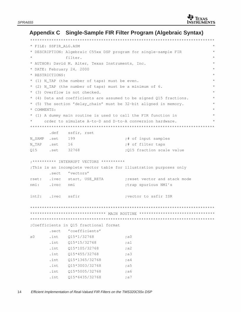
Appendix C Single-Sample FIR Filter Program (Algebraic Syntax)******************************************************************************
* FILE: SSFIR_ALG.ASM *
* DESCRIPTION: Algebraic C55xx DSP program for single–sample FIR *
* filter. *
* AUTHOR: David M. Alter, Texas Instruments, Inc. *
* DATE: February 24, 2000 *
* RESTRICTIONS: *
* (1) N_TAP (the number of taps) must be even. *
* (2) N_TAP (the number of taps) must be a minimum of 6. *
* (3) Overflow is not checked. *
* (4) Data and coefficients are assumed to be signed Q15 fractions. *
* (5) The section ”delay_chain” must be 32–bit aligned in memory. *
* COMMENTS: *
* (1) A dummy main routine is used to call the FIR function in *
* order to simulate A–to–D and D–to–A conversion hardware. *
******************************************************************************
.def ssfir, rset
N_SAMP .set 199 ;# of input samples
N_TAP .set 16 ;# of filter taps
Q15 .set 32768 ;Q15 fraction scale value
;********** INTERRUPT VECTORS **********
;This is an incomplete vector table for illustration purposes only
.sect ”vectors”
rset: .ivec start, USE_RETA ;reset vector and stack mode
nmi: .ivec nmi ;trap spurious NMI’s
int2: .ivec ssfir ;vector to ssfir ISR
******************************************************************************
******************************** MAIN ROUTINE ********************************
******************************************************************************
;Coefficients in Q15 fractional format
.sect ”coefficients”
a0 .int Q15*1/32768 ;a0
.int Q15*15/32768 ;a1
.int Q15*105/32768 ;a2
.int Q15*455/32768 ;a3
.int Q15*1365/32768 ;a4
.int Q15*3003/32768 ;a5
.int Q15*5005/32768 ;a6
.int Q15*6435/32768 ;a7

SPRA655
15 Efficient Implementation of Real-Valued FIR Filters on the TMS320C55x DSP
.int Q15*6435/32768 ;a8
.int Q15*5005/32768 ;a9
.int Q15*3003/32768 ;a10
.int Q15*1365/32768 ;a11
.int Q15*455/32768 ;a12
.int Q15*105/32768 ;a13
.int Q15*15/32768 ;a14
.int Q15*1/32768 ;a15
;Input data in Q15 fractional format
.sect ”input_data”
x .copy DUALSINE.DAT ;label at oldest input
;Output array in Q15 fractional format
y .usect ”output_data”, N_SAMP ;label at oldest output
;Simulate A/D and D/A converters using memory
.bss ADC,1 ;simulated A/D converter
.bss DAC,1 ;simulated D/A converter
;Filter delay chain has the following structure:
; word 0 = PRECALC[31:16]
; word 1 = PRECALC[15:0]
; word 2 = PRECALC[39:32]
; word 3 = CDPSAVE
; word 4 = start of delay chain
; ...
; word N_TAP+3 = end of delay chain
dchain .usect ”delay_chain”, N_TAP+4, 1 ;delay chain structure
d0 .set dchain+4 ;label at chain start
;********** DSP INITIALIZATION **********
.text
start:
bit(ST1, #ST1_C54CM) = #0 ;C54x compatibility off
.c54cm_off
bit(ST2, #ST2_ARMS) = #0 ;compiler mode off
.arms_off

SPRA655
16 Efficient Implementation of Real-Valued FIR Filters on the TMS320C55x DSP
;Setup the stack
SP_stack_len .set 100
SSP_stack_len .set 100
SP_stack .usect ”stack”, SP_stack_len
SSP_stack .usect ”stack”, SSP_stack_len
XSP = #( SP_stack + SP_stack_len )
SSP = #( SSP_stack + SSP_stack_len )
;Initialize the filter delay chain to zero
XAR0 = #dchain ;pointer to delay chain
AC0 = #0 ;clear AC0
||repeat( #((N_TAP+4)/2 – 1) ) ;repeat single
dbl(*AR0+) = AC0 ;clear the delay chain
;Pointer setup
XAR3 = #x ;pointer to input array
XAR4 = #y ;pointer to output array
;Start the main routine loop
T0 = #N_SAMP ;initialize loop counter
loop:
T0 = T0 – #1 ;decrement the loop counter
AC0 = *AR3+ ;read new input value
*(#ADC) = AC0 ;put new value into ADC
intr(#2) ;simulate an ADC interrupt
AC0 = *(#DAC) ;read FIR output from DAC
*AR4+ = AC0 ;write it to the output array
if (T0 > #0) goto loop ;loop test
end: goto end ;trap the end of the program
;*****************************************************************************
;*********************** SINGLE–SAMPLE FIR FILTER ISR ************************
;*****************************************************************************
.text
ssfir:
SPRA655
17 Efficient Implementation of Real-Valued FIR Filters on the TMS320C55x DSP
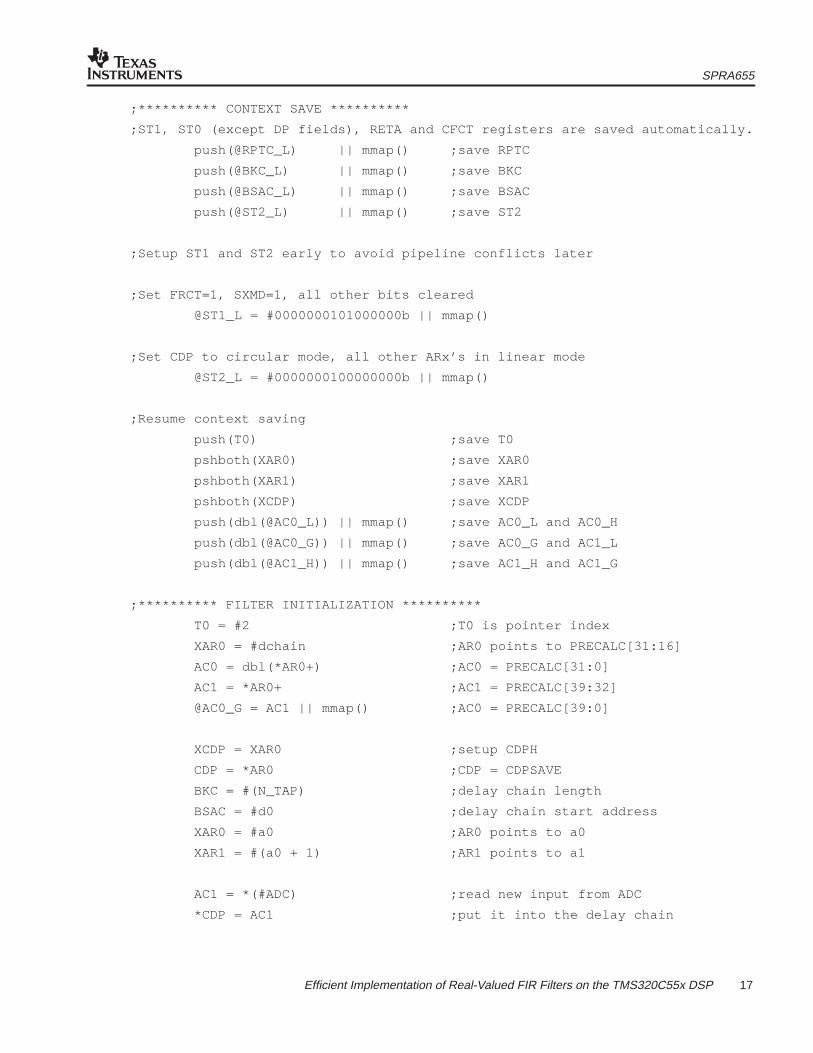
;********** CONTEXT SAVE **********
;ST1, ST0 (except DP fields), RETA and CFCT registers are saved automatically.
push(@RPTC_L) || mmap() ;save RPTC
push(@BKC_L) || mmap() ;save BKC
push(@BSAC_L) || mmap() ;save BSAC
push(@ST2_L) || mmap() ;save ST2
;Setup ST1 and ST2 early to avoid pipeline conflicts later
;Set FRCT=1, SXMD=1, all other bits cleared
@ST1_L = #0000000101000000b || mmap()
;Set CDP to circular mode, all other ARx’s in linear mode
@ST2_L = #0000000100000000b || mmap()
;Resume context saving
push(T0) ;save T0
pshboth(XAR0) ;save XAR0
pshboth(XAR1) ;save XAR1
pshboth(XCDP) ;save XCDP
push(dbl(@AC0_L)) || mmap() ;save AC0_L and AC0_H
push(dbl(@AC0_G)) || mmap() ;save AC0_G and AC1_L
push(dbl(@AC1_H)) || mmap() ;save AC1_H and AC1_G
;********** FILTER INITIALIZATION **********
T0 = #2 ;T0 is pointer index
XAR0 = #dchain ;AR0 points to PRECALC[31:16]
AC0 = dbl(*AR0+) ;AC0 = PRECALC[31:0]
AC1 = *AR0+ ;AC1 = PRECALC[39:32]
@AC0_G = AC1 || mmap() ;AC0 = PRECALC[39:0]
XCDP = XAR0 ;setup CDPH
CDP = *AR0 ;CDP = CDPSAVE
BKC = #(N_TAP) ;delay chain length
BSAC = #d0 ;delay chain start address
XAR0 = #a0 ;AR0 points to a0
XAR1 = #(a0 + 1) ;AR1 points to a1
AC1 = *(#ADC) ;read new input from ADC
*CDP = AC1 ;put it into the delay chain

SPRA655
18 Efficient Implementation of Real-Valued FIR Filters on the TMS320C55x DSP
;********** FILTER KERNEL **********
;First dual–MAC is MAC||MPY
AC0 = AC0 + ( *(AR0+T0) * coef(*(CDP+T0)) ),
AC1 = *(AR1+T0) * coef(*(CDP+T0))
||repeat( #(N_TAP/2 – 3) )
;Middle dual–MACs are all MAC||MAC
AC0 = AC0 + ( *(AR0+T0) * coef(*(CDP+T0)) ),
AC1 = AC1 + ( *(AR1+T0) * coef(*(CDP+T0)) )
;Final dual–MAC has different pointer adjustments
AC0 = AC0 + ( *AR0 * coef(*CDP+) ),
AC1 = AC1 + ( *AR1 * coef(*CDP+) )
;********** FILTER TERMINATION **********
XAR0 = #dchain ;AR1 points to CDPSAVE
dbl(*AR0+) = AC1 ;save PRECALC[31:0]
*AR0+ = HI(AC1<<#(–16)) ;save PRECALC[39:32]
*AR0 = CDP ;save CDP
*(#DAC) = HI(AC0) ;send result to the DAC
;********** CONTEXT RESTORE **********
dbl(@AC1_H) = pop() || mmap() ;restore AC1_G and AC1_H
dbl(@AC0_G) = pop() || mmap() ;restore AC1_L and AC0_G
dbl(@AC0_L) = pop() || mmap() ;restore AC0_H and AC0_L
XCDP = popboth() ;restore XCDP
XAR1 = popboth() ;restore XAR1
XAR0 = popboth() ;restore XAR0
T0 = pop() ;restore T0
@ST2_L = pop() || mmap() ;restore ST2
@BSAC_L = pop() || mmap() ;restore BSAC
@BKC_L = pop() || mmap() ;restore BKC
@RPTC_L = pop() || mmap() ;restore RPTC
return_int ;return from interrupt
;End of single–sample FIR algebraic program
SPRA655
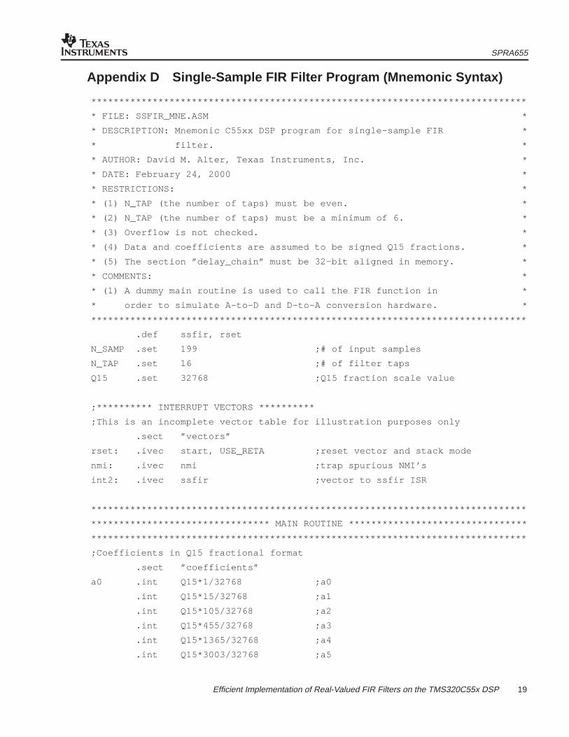
19 Efficient Implementation of Real-Valued FIR Filters on the TMS320C55x DSP
Appendix D Single-Sample FIR Filter Program (Mnemonic Syntax)
******************************************************************************
* FILE: SSFIR_MNE.ASM *
* DESCRIPTION: Mnemonic C55xx DSP program for single–sample FIR *
* filter. *
* AUTHOR: David M. Alter, Texas Instruments, Inc. *
* DATE: February 24, 2000 *
* RESTRICTIONS: *
* (1) N_TAP (the number of taps) must be even. *
* (2) N_TAP (the number of taps) must be a minimum of 6. *
* (3) Overflow is not checked. *
* (4) Data and coefficients are assumed to be signed Q15 fractions. *
* (5) The section ”delay_chain” must be 32–bit aligned in memory. *
* COMMENTS: *
* (1) A dummy main routine is used to call the FIR function in *
* order to simulate A–to–D and D–to–A conversion hardware. *
******************************************************************************
.def ssfir, rset
N_SAMP .set 199 ;# of input samples
N_TAP .set 16 ;# of filter taps
Q15 .set 32768 ;Q15 fraction scale value
;********** INTERRUPT VECTORS **********
;This is an incomplete vector table for illustration purposes only
.sect ”vectors”
rset: .ivec start, USE_RETA ;reset vector and stack mode
nmi: .ivec nmi ;trap spurious NMI’s
int2: .ivec ssfir ;vector to ssfir ISR
******************************************************************************
******************************** MAIN ROUTINE ********************************
******************************************************************************
;Coefficients in Q15 fractional format
.sect ”coefficients”
a0 .int Q15*1/32768 ;a0
.int Q15*15/32768 ;a1
.int Q15*105/32768 ;a2
.int Q15*455/32768 ;a3
.int Q15*1365/32768 ;a4
.int Q15*3003/32768 ;a5

SPRA655
20 Efficient Implementation of Real-Valued FIR Filters on the TMS320C55x DSP
.int Q15*5005/32768 ;a6
.int Q15*6435/32768 ;a7
.int Q15*6435/32768 ;a8
.int Q15*5005/32768 ;a9
.int Q15*3003/32768 ;a10
.int Q15*1365/32768 ;a11
.int Q15*455/32768 ;a12
.int Q15*105/32768 ;a13
.int Q15*15/32768 ;a14
.int Q15*1/32768 ;a15
;Input data in Q15 fractional format
.sect ”input_data”
x .copy DUALSINE.DAT ;label at oldest input
;Output array in Q15 fractional format
y .usect ”output_data”, N_SAMP ;label at oldest output
;Simulate A/D and D/A converters using memory
.bss ADC,1 ;simulated A/D converter
.bss DAC,1 ;simulated D/A converter
;Filter delay chain has the following structure:
; word 0 = PRECALC[31:16]
; word 1 = PRECALC[15:0]
; word 2 = PRECALC[39:32]
; word 3 = CDPSAVE
; word 4 = start of delay chain
; ...
; word N_TAP+3 = end of delay chain
dchain .usect ”delay_chain”, N_TAP+4, 1 ;delay chain structure
d0 .set dchain+4 ;label at chain start
;********** DSP INITIALIZATION **********
.text
start:
BCLR C54CM ;C54x compatibility off
.c54cm_off

SPRA655
21 Efficient Implementation of Real-Valued FIR Filters on the TMS320C55x DSP
BCLR ARMS ;compiler mode off
.arms_off
;Setup the stack
SP_stack_len .set 100
SSP_stack_len .set 100
SP_stack .usect ”stack”, SP_stack_len
SSP_stack .usect ”stack”, SSP_stack_len
AMOV #( SP_stack + SP_stack_len ), XSP
MOV #( SSP_stack + SSP_stack_len ), SSP
;Initialize the filter delay chain to zero
AMOV #dchain, XAR0 ;pointer to delay chain
MOV #0, AC0 ;clear AC0
||RPT #((N_TAP+4)/2 – 1) ;repeat single
MOV AC0, dbl(*AR0+) ;clear the delay chain
;Pointer setup
AMOV #x, XAR3 ;pointer to input array
AMOV #y, XAR4 ;pointer to output array
;Start the main routine loop
MOV #N_SAMP, T0 ;initialize loop counter
loop:
SUB #1, T0, T0 ;decrement the loop counter
MOV *AR3+, AC0 ;read new input value
MOV AC0, *(#ADC) ;put new value into ADC
INTR #2 ;simulate an ADC interrupt
MOV *(#DAC), AC0 ;read FIR output from DAC
MOV AC0, *AR4+ ;write it to the output array
BCC loop, T0 > #0 ;loop test
end: B end ;trap the end of the program

SPRA655
22 Efficient Implementation of Real-Valued FIR Filters on the TMS320C55x DSP
;*****************************************************************************
;*********************** SINGLE–SAMPLE FIR FILTER ISR ************************
;*****************************************************************************
.text
ssfir:
;********** CONTEXT SAVE **********
;ST1, ST0 (except DP fields), RETA and CFCT registers are saved automatically.
PSH mmap(@RPTC) ;save RPTC
PSH mmap(@BKC) ;save BKC
PSH mmap(@BSAC) ;save BSAC
PSH mmap(@ST2_55) ;save ST2
;Setup ST1 and ST2 early to avoid pipeline conflicts later
;Set FRCT=1, SXMD=1, all other bits cleared
MOV #0000000101000000b, mmap(@ST1_55)
;Set CDP to circular mode, all other ARx’s in linear mode
MOV #0000000100000000b, mmap(@ST2_55)
;Resume context saving
PSH T0 ;save T0
PSHBOTH XAR0 ;save XAR0
PSHBOTH XAR1 ;save XAR1
PSHBOTH XCDP ;save XCDP
PSH dbl(mmap(@AC0L)) ;save AC0L and AC0H
PSH dbl(mmap(@AC0G)) ;save AC0G and AC1L
PSH dbl(mmap(@AC1H)) ;save AC1H and AC1G
;********** FILTER INITIALIZATION **********
MOV #2, T0 ;T0 is pointer index
AMOV #dchain, XAR0 ;AR0 points to PRECALC[31:16]
MOV dbl(*AR0+), AC0 ;AC0 = PRECALC[31:0]
MOV *AR0+, AC1 ;AC1 = PRECALC[39:32]
MOV AC1, mmap(@AC0G) ;AC0 = PRECALC[39:0]
MOV XAR0, XCDP ;setup CDPH
MOV *AR0, CDP ;CDP = CDPSAVE
MOV #(N_TAP), BKC ;delay chain length
MOV #d0, BSAC ;delay chain start address
AMOV #a0, XAR0 ;AR0 points to a0
AMOV #(a0 + 1), XAR1 ;AR1 points to a1
SPRA655
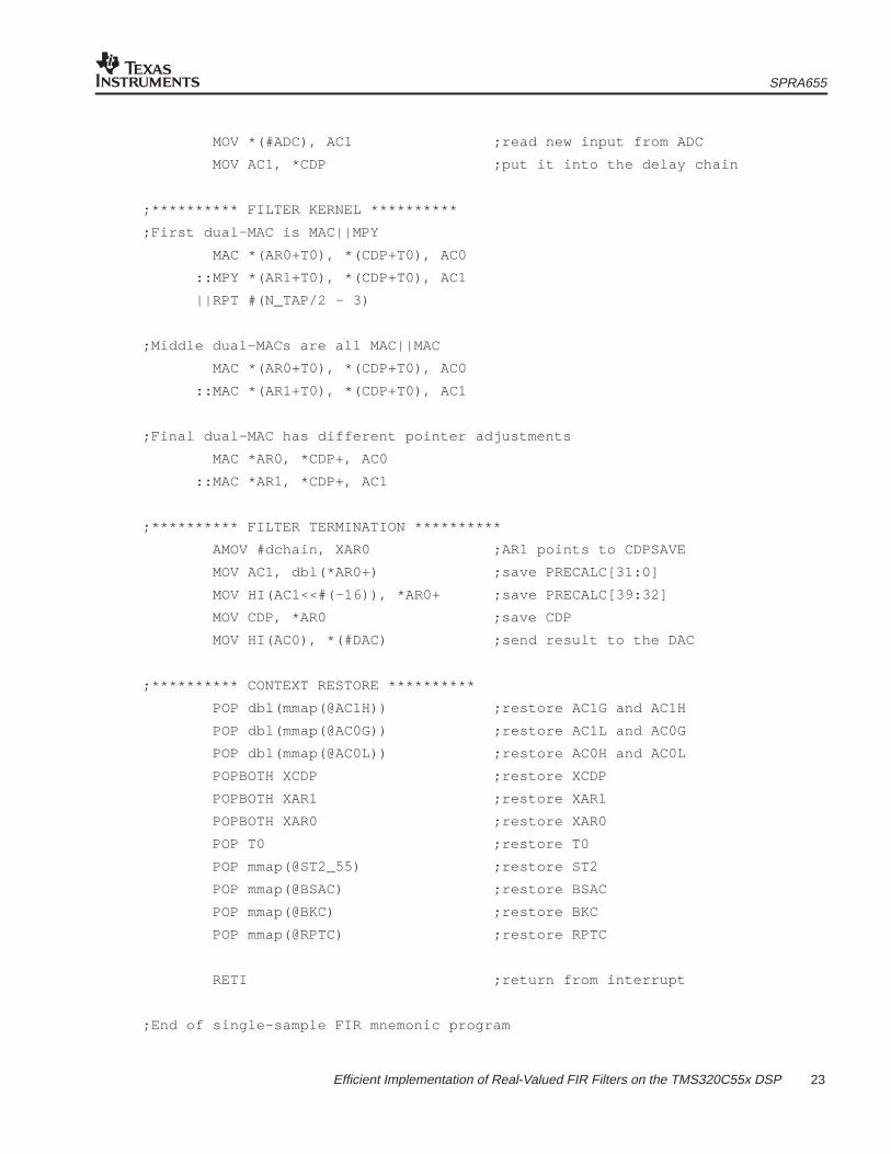
23 Efficient Implementation of Real-Valued FIR Filters on the TMS320C55x DSP
MOV *(#ADC), AC1 ;read new input from ADC
MOV AC1, *CDP ;put it into the delay chain
;********** FILTER KERNEL **********
;First dual–MAC is MAC||MPY
MAC *(AR0+T0), *(CDP+T0), AC0
::MPY *(AR1+T0), *(CDP+T0), AC1
||RPT #(N_TAP/2 – 3)
;Middle dual–MACs are all MAC||MAC
MAC *(AR0+T0), *(CDP+T0), AC0
::MAC *(AR1+T0), *(CDP+T0), AC1
;Final dual–MAC has different pointer adjustments
MAC *AR0, *CDP+, AC0
::MAC *AR1, *CDP+, AC1
;********** FILTER TERMINATION **********
AMOV #dchain, XAR0 ;AR1 points to CDPSAVE
MOV AC1, dbl(*AR0+) ;save PRECALC[31:0]
MOV HI(AC1<<#(–16)), *AR0+ ;save PRECALC[39:32]
MOV CDP, *AR0 ;save CDP
MOV HI(AC0), *(#DAC) ;send result to the DAC
;********** CONTEXT RESTORE **********
POP dbl(mmap(@AC1H)) ;restore AC1G and AC1H
POP dbl(mmap(@AC0G)) ;restore AC1L and AC0G
POP dbl(mmap(@AC0L)) ;restore AC0H and AC0L
POPBOTH XCDP ;restore XCDP
POPBOTH XAR1 ;restore XAR1
POPBOTH XAR0 ;restore XAR0
POP T0 ;restore T0
POP mmap(@ST2_55) ;restore ST2
POP mmap(@BSAC) ;restore BSAC
POP mmap(@BKC) ;restore BKC
POP mmap(@RPTC) ;restore RPTC
RETI ;return from interrupt
;End of single–sample FIR mnemonic program

SPRA655
24 Efficient IMplementation of Real-Valued FIR Filters on the TMS320c55xx DSP
Appendix E Include File Containing Example Input Data
******************************************************************************
* FILE: DUALSINE.DAT *
* DESCRIPTION: Include file for example FIR filter programs. *
* AUTHOR: David M. Alter, Texas Instruments, Inc. *
* DATE: February 23, 2000 *
******************************************************************************
.int 0xee4d, 0xc000, 0x08bb, 0x3709, 0xdc9a, 0xae4d, 0xf7b2
.int 0x2600, 0xcca9, 0x9e5b, 0xe93f, 0x178c, 0xc010, 0x91c2
.int 0xded1, 0x0d1e, 0xb80f, 0x89c2, 0xd971, 0x07bf, 0xb573
.int 0x8726, 0xd9a9, 0x07f7, 0xb87e, 0x8a30, 0xdf73, 0x0dc0
.int 0xc0e1, 0x9294, 0xea3a, 0x1888, 0xcdc8, 0x9f7a, 0xf8ed
.int 0x273b, 0xdde9, 0xaf9c, 0x0a16, 0x3864, 0xefac, 0xc15e
.int 0x1c00, 0x4a4e, 0x014a, 0xd2fd, 0x2ce2, 0x5b30, 0x1104
.int 0xe2b6, 0x3b0f, 0x695c, 0x1d49, 0xeefb, 0x451e, 0x736b
.int 0x24e1, 0xf694, 0x4a0f, 0x785c, 0x270b, 0xf8bd, 0x4963
.int 0x77b1, 0x238f, 0xf541, 0x432d, 0x717a, 0x1ac6, 0xec78
.int 0x380a, 0x6657, 0x0d90, 0xdf42, 0x2915, 0x5763, 0xfd3d
.int 0xceef, 0x17cc, 0x461a, 0xeb6c, 0xbd1f, 0x05e6, 0x3434
.int 0xd9e4, 0xab96, 0xf52c, 0x2379, 0xca62, 0x9c15, 0xe747
.int 0x1594, 0xbe73, 0x9025, 0xdd99, 0x0be7, 0xb745, 0x88f8
.int 0xd91a, 0x0767, 0xb591, 0x8743, 0xda3b, 0x0888, 0xb980
.int 0x8b32, 0xe0df, 0x0f2c, 0xc2ae, 0x9461, 0xec5d, 0x1aaa
.int 0xd032, 0xa1e5, 0xfb90, 0x29de, 0xe0b4, 0xb266, 0x0cf6
.int 0x3b44, 0xf28f, 0xc441, 0x1ed4, 0x4d21, 0x03fc, 0xd5af
.int 0x2f62, 0x5daf, 0x1341, 0xe4f3, 0x3cfb, 0x6b48, 0x1ed7
.int 0xf08a, 0x4645, 0x7492, 0x2599, 0xf74c, 0x4a53, 0x78a1
.int 0x26da, 0xf88d, 0x48bf, 0x770c, 0x227a, 0xf42d, 0x41af
.int 0x6ffd, 0x18e9, 0xea9b, 0x35d9, 0x6427, 0x0b1a, 0xdccc
.int 0x266a, 0x54b7, 0xfa6d, 0xcc1f, 0x14ea, 0x4337, 0xe88a
.int 0xba3c, 0x0316, 0x3164, 0xd738, 0xa8eb, 0xf2b6, 0x2103
.int 0xc831, 0x99e4, 0xe569, 0x13b6, 0xbcf4, 0x8ea6, 0xdc83
.int 0x0ad0, 0xb69e, 0x8851, 0xd8e6, 0x0734, 0xb5d2, 0x8784
.int 0xdaef, 0x093c, 0xbaa2, 0x8c55, 0xe269, 0x10b6, 0xc496
.int 0x9648, 0xee96, 0x1ce3, 0xd2ae, 0xa461, 0xfe3f, 0x2c8d
.int 0xe385, 0xb537, 0x0fd7

SPRA655
25 Efficient Implementation of Real Valued FIR Filters on the TMS320C55xx DSP
Appendix F Output From Block FIR Filter Program
The first value, 0xe2a3, exists in data memory at address y. There is a total of 184 outputs.
0xe2a3, 0xde74, 0xdb1e, 0xd85f, 0xd53d, 0xd203, 0xcfb6, 0xce12
0xcc1c, 0xca1c, 0xc916, 0xc8c4, 0xc827, 0xc788, 0xc7e7, 0xc8fb
0xc9c5, 0xca89, 0xcc46, 0xceb2, 0xd0ca, 0xd2d2, 0xd5c4, 0xd957
0xdc85, 0xdf8f, 0xe370, 0xe7db, 0xebca, 0xef7d, 0xf3ee, 0xf8ce
0xfd16, 0x0107, 0x0599, 0x0a7e, 0x0eb0, 0x126d, 0x16b0, 0x1b2b
0x1ed7, 0x21f5, 0x257f, 0x292a, 0x2bf0, 0x2e13, 0x308f, 0x3319
0x34ae, 0x3593, 0x36c4, 0x37fa, 0x3833, 0x37b5, 0x3781, 0x3751
0x3624, 0x3445, 0x32b4, 0x312e, 0x2eb6, 0x2b98, 0x28d6, 0x262e
0x22a7, 0x1e8c, 0x1ae2, 0x176a, 0x1329, 0x0e6d, 0x0a3c, 0x0658
0x01c6, 0xfcd5, 0xf88c, 0xf4ab, 0xf039, 0xeb85, 0xe793, 0xe426
0xe042, 0xdc35, 0xd904, 0xd66d, 0xd377, 0xd06b, 0xce4f, 0xccdf
0xcb1d, 0xc955, 0xc886, 0xc86e, 0xc80b, 0xc7a5, 0xc83d, 0xc98b
0xca8d, 0xcb88, 0xcd7a, 0xd01a, 0xd263, 0xd499, 0xd7b8, 0xdb73
0xdec6, 0xe1f2, 0xe5f1, 0xea76, 0xee7b, 0xf23f, 0xf6bc, 0xfba4
0xfff1, 0x03e1, 0x086e, 0x0d49, 0x116c, 0x1517, 0x1943, 0x1da2
0x212f, 0x242b, 0x278f, 0x2b10, 0x2da9, 0x2f9c, 0x31e6, 0x343c
0x359b, 0x3648, 0x3741, 0x383e, 0x383d, 0x3786, 0x3718, 0x36ae
0x354a, 0x3333, 0x316e, 0x2fb5, 0x2d0d, 0x29c1, 0x26d4, 0x2405
0x2059, 0x1c1e, 0x1858, 0x14c7, 0x1072, 0x0ba6, 0x076a, 0x037e
0xfeea, 0xf9fc, 0xf5b9, 0xf1e4, 0xed82, 0xe8e2, 0xe509, 0xe1b8
0xddf4, 0xda0b, 0xd701, 0xd495, 0xd1cc, 0xcef1, 0xcd07, 0xcbcb
0xca41, 0xc8b0, 0xc81a, 0xc83b, 0xc811, 0xc7e6, 0xc8b7, 0xca3d
0xcb76, 0xcca7, 0xcecd, 0xd19f, 0xd418, 0xd67b, 0xd9c3, 0xdda5

SPRA655
26 Efficient Implementation of Real-Valued FIR Filters on the TMS320C55x DSP
Appendix G Output From Single-Sample FIR Filter Program
The first value, 0xFFFF, exists in data memory at address y. There is a total of 199 outputs.Values 16 to 199 are identical to block FIR output values 1 to 184 listed in Appendix D.
0xFFFF, 0xFFFD, 0xFFEA, 0xFF8E, 0xFE6D, 0xFBFD, 0xF868, 0xF515
0xF3B6, 0xF42E, 0xF433, 0xF1E5, 0xEDF4, 0xEA23, 0xE6A4, 0xE2A3
0xDE74, 0xDB1E, 0xD85F, 0xD53D, 0xD203, 0xCFB6, 0xCE12, 0xCC1C
0xCA1C, 0xC916, 0xC8C4, 0xC827, 0xC788, 0xC7E7, 0xC8FB, 0xC9C5
0xCA89, 0xCC46, 0xCEB2, 0xD0CA, 0xD2D2, 0xD5C4, 0xD957, 0xDC85
0xDF8F, 0xE370, 0xE7DB, 0xEBCA, 0xEF7D, 0xF3EE, 0xF8CE, 0xFD16
0x0107, 0x0599, 0x0A7E, 0x0EB0, 0x126D, 0x16B0, 0x1B2B, 0x1ED7
0x21F5, 0x257F, 0x292A, 0x2BF0, 0x2E13, 0x308F, 0x3319, 0x34AE
0x3593, 0x36C4, 0x37FA, 0x3833, 0x37B5, 0x3781, 0x3751, 0x3624
0x3445, 0x32B4, 0x312E, 0x2EB6, 0x2B98, 0x28D6, 0x262E, 0x22A7
0x1E8C, 0x1AE2, 0x176A, 0x1329, 0x0E6D, 0x0A3C, 0x0658, 0x01C6
0xFCD5, 0xF88C, 0xF4AB, 0xF039, 0xEB85, 0xE793, 0xE426, 0xE042
0xDC35, 0xD904, 0xD66D, 0xD377, 0xD06B, 0xCE4F, 0xCCDF, 0xCB1D
0xC955, 0xC886, 0xC86E, 0xC80B, 0xC7A5, 0xC83D, 0xC98B, 0xCA8D
0xCB88, 0xCD7A, 0xD01A, 0xD263, 0xD499, 0xD7B8, 0xDB73, 0xDEC6
0xE1F2, 0xE5F1, 0xEA76, 0xEE7B, 0xF23F, 0xF6BC, 0xFBA4, 0xFFF1
0x03E1, 0x086E, 0x0D49, 0x116C, 0x1517, 0x1943, 0x1DA2, 0x212F
0x242B, 0x278F, 0x2B10, 0x2DA9, 0x2F9C, 0x31E6, 0x343C, 0x359B
0x3648, 0x3741, 0x383E, 0x383D, 0x3786, 0x3718, 0x36AE, 0x354A
0x3333, 0x316E, 0x2FB5, 0x2D0D, 0x29C1, 0x26D4, 0x2405, 0x2059
0x1C1E, 0x1858, 0x14C7, 0x1072, 0x0BA6, 0x076A, 0x037E, 0xFEEA
0xF9FC, 0xF5B9, 0xF1E4, 0xED82, 0xE8E2, 0xE509, 0xE1B8, 0xDDF4
0xDA0B, 0xD701, 0xD495, 0xD1CC, 0xCEF1, 0xCD07, 0xCBCB, 0xCA41
0xC8B0, 0xC81A, 0xC83B, 0xC811, 0xC7E6, 0xC8B7, 0xCA3D, 0xCB76
0xCCA7, 0xCECD, 0xD19F, 0xD418, 0xD67B, 0xD9C3, 0xDDA5

IMPORTANT NOTICE
Texas Instruments and its subsidiaries (TI) reserve the right to make changes to their products or to discontinueany product or service without notice, and advise customers to obtain the latest version of relevant informationto verify, before placing orders, that information being relied on is current and complete. All products are soldsubject to the terms and conditions of sale supplied at the time of order acknowledgment, including thosepertaining to warranty, patent infringement, and limitation of liability.
TI warrants performance of its semiconductor products to the specifications applicable at the time of sale inaccordance with TI’s standard warranty. Testing and other quality control techniques are utilized to the extentTI deems necessary to support this warranty. Specific testing of all parameters of each device is not necessarilyperformed, except those mandated by government requirements.
Customers are responsible for their applications using TI components.
In order to minimize risks associated with the customer’s applications, adequate design and operatingsafeguards must be provided by the customer to minimize inherent or procedural hazards.
TI assumes no liability for applications assistance or customer product design. TI does not warrant or representthat any license, either express or implied, is granted under any patent right, copyright, mask work right, or otherintellectual property right of TI covering or relating to any combination, machine, or process in which suchsemiconductor products or services might be or are used. TI’s publication of information regarding any thirdparty’s products or services does not constitute TI’s approval, warranty or endorsement thereof.
Copyright 2000, Texas Instruments Incorporated