efr32mg1 errata mighty gecko - silicon labs · attempting to take an adc sample too soon after por...
TRANSCRIPT

Mighty GeckoEFR32MG1 Errata
This document contains information on the errata of EFR32MG1. The latest available revision of this device is revision C. Note thatmany issues on this device family are resolved in EFR32MG14 devices. The EFR32MG14 devices are very similar to EFR32MG1,and migration will require few changes. More information can be found here: https://www.silabs.com/products/wireless.
For errata on older revisions, please refer to the errata history section for the device. The revision information is typically specified inor near the trace code on the device. Refer to the package marking information in the data sheet for more information.
Errata effective date: June, 2018.
silabs.com | Building a more connected world. Rev. 1.7

1. Active Errata Summary
These tables list all known errata for the EFR32MG1 and all unresolved errata in revision C of the EFR32MG1.
Table 1.1. Errata History Overview
Designator Title/Problem Exists on Revision:
B C
ADC_E202 Wait After POR or EM4S Wakeup X X
ADC_E206 PROGERRIF (Program Error Interrupt Flag) Will Not Clear X X
ADC_E207 ADC Scan Repeat Mode with APORT X X
ADC_E208 ADC Interrupt Flags X X
ADC_E209 ADC and PRS Triggers X X
ADC_E210 ADC with PRS and Software Triggers X X
ADC_E211 ADC Single Repeat Mode and Tailgating X X
ADC_E212 ADC with PRS in ASYNC Mode X X
ADC_E213 ADC KEEPINSLOWACC Mode X X
ADC_E214 Using ADC CHCONMODE with PRS X X
ADC_E215 ADC CHCONMODE Set to MAXRESP Causes Extra Latency X X
ADC_E216 ADC Conversion Start Delay X X
ADC_E217 Multiple CLK Mode Switches X X
ADC_E218 SINGLEACT and SCANACT Status Flags Delayed X X
ADC_E219 STOP Command Causing FIFO Corruption X X
ADC_E220 AUXHFRCO in ASYNC mode with ASYNC CLK in ASNEEDED mode X X
ADC_E221 ADC Temperature Sensor Must be Used in LOWACC Mode X X
ADC_E222 ADC EM2 Wakeup on a Comparator Match Disables EM2 Entry X X
ADC_E223 Delayed ADC Conversion or Warmup Start X X
ADC_E224 ADC Warm-Up Ready Can Cause ACMP to Not Function X X
ADC_E226 SCANSTOP Does Not Immediately Stop the Ongoing Sample X X
ADC_E227 New Conversion Triggers Cause Jitter to the Ongoing Conversions X X
CORE_E201 SYSTICK and an External Clock X X
CRYPTO_E201 Full CRYPTO Not Available in All Value Devices — X
CUR_E201 EM2 and EM3 Current Consumption X X
CUR_E202 EM2/3 Current Consumption at Cold Temperatures X —
DBG_E201 AUXHFRCO Debug Limitations X X
DBG_E202 Debug Access to ADC and LEUART not Functioning as Intended X X
DBG_E204 Debug Recovery with JTAG Does Not Work X X
DCDC_E201 DCDC Stops Regulating During a Fast EM0/1 to EM2/3/4H Transition X —
DCDC_E202 Regulated DCDC Output Can Dip on EM2 Entry X X
EFR32MG1 ErrataActive Errata Summary
silabs.com | Building a more connected world. Rev. 1.7 | 2

Designator Title/Problem Exists on Revision:
B C
DCDC_E203 Regulated DCDC Output Can Dip on EM2 Entry if not in LN Mode X X
DCDC_E205 Delay Required after Enabling the DC-DC Before Entering EM2/3/4H X X
DCDC_E206 Reset During Radio Operation With DC-DC Results in DVDD Brown Out X X
EFR_E201 Bit Access Not Supported for Low Energy Peripherals X X
EFR_E202 Read-Clear Access for LETIMER0 and RTCC Interrupts X X
EMU_E201 High Temperature Operation X X
EMU_E204 Restrictions Writing TEMPHIGH and TEMPLOW X X
EMU_E205 Restrictions Reading TEMP X X
EMU_E207 GPIO State can be Lost During EM4 Recovery X X
EMU_E208 Occasional Full Reset After Exiting EM4H X X
EMU_E209 Potential EM2 Lock-up when using IDAC or the Debugger with the LDMA X X
EMU_E210 Potential Power-Down When Entering EM2 X X
EMU_E215 Device May Brown Out After Energy Mode Transition X X
EMU_E216 EM4H I/O Retention Cannot Be Disabled X X
FLASH_E201 Potential Program Failure after Power On X X
GPIO_E201 GPIO Default Slew Rate X —
I2C_E201 I2C ABORT Command X X
I2C_E206 Slave Holds SCL Low After Losing Arbitration X X
IDAC_E201 IDAC CURSTABLE Bit Not Reliable X X
LEUART_E201 Restrictions Setting TXDMAWU/RXDMAWU of LEUARTn_CTRL X X
RADIO_E201 Receive Sensitivity X X
RADIO_E202 802.15.4 Channel 14 X X
RADIO_E203 Bluetooth Smart Channel 26 X X
RADIO_E204 Increased EVM on Selected Channels X X
RADIO_E206 Bluetooth Smart Receive Sensitivity X X
RADIO_E207 Sensitivity at 2.42 GHz X X
RMU_E201 CTRL Register Reset on All Resets X X
RMU_E202 External Debug Access Not Available After Watchdog or Lockup Full Reset X X
RTCC_E201 RTCC Does Not Support Compare/Capture Wrap with Prescaler X X
RTCC_E202 RTCC Triggers to LETIMER Not Safe X X
RTCC_E203 Potential Stability Issue with RTCC Registers X X
TIMER_E201 Timer in Input Capture Mode Can Stop Counting X X
USART_E202 Incorrect 8-bit Timer Operation in Asynchronous Mode X X
EFR32MG1 ErrataActive Errata Summary
silabs.com | Building a more connected world. Rev. 1.7 | 3
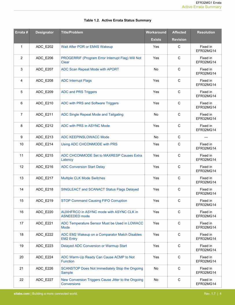
Table 1.2. Active Errata Status Summary
Errata # Designator Title/Problem Workaround
Exists
Affected
Revision
Resolution
1 ADC_E202 Wait After POR or EM4S Wakeup Yes C Fixed inEFR32MG14
2 ADC_E206 PROGERRIF (Program Error Interrupt Flag) Will NotClear
Yes C Fixed inEFR32MG14
3 ADC_E207 ADC Scan Repeat Mode with APORT No C Fixed inEFR32MG14
4 ADC_E208 ADC Interrupt Flags Yes C Fixed inEFR32MG14
5 ADC_E209 ADC and PRS Triggers Yes C Fixed inEFR32MG14
6 ADC_E210 ADC with PRS and Software Triggers Yes C Fixed inEFR32MG14
7 ADC_E211 ADC Single Repeat Mode and Tailgating No C Fixed inEFR32MG14
8 ADC_E212 ADC with PRS in ASYNC Mode Yes C Fixed inEFR32MG14
9 ADC_E213 ADC KEEPINSLOWACC Mode No C —
10 ADC_E214 Using ADC CHCONMODE with PRS Yes C Fixed inEFR32MG14
11 ADC_E215 ADC CHCONMODE Set to MAXRESP Causes ExtraLatency
Yes C Fixed inEFR32MG14
12 ADC_E216 ADC Conversion Start Delay Yes C Fixed inEFR32MG14
13 ADC_E217 Multiple CLK Mode Switches Yes C Fixed inEFR32MG14
14 ADC_E218 SINGLEACT and SCANACT Status Flags Delayed Yes C Fixed inEFR32MG14
15 ADC_E219 STOP Command Causing FIFO Corruption Yes C Fixed inEFR32MG14
16 ADC_E220 AUXHFRCO in ASYNC mode with ASYNC CLK inASNEEDED mode
Yes C Fixed inEFR32MG14
17 ADC_E221 ADC Temperature Sensor Must be Used in LOWACCMode
Yes C Fixed inEFR32MG14
18 ADC_E222 ADC EM2 Wakeup on a Comparator Match DisablesEM2 Entry
Yes C Fixed inEFR32MG14
19 ADC_E223 Delayed ADC Conversion or Warmup Start Yes C Fixed inEFR32MG14
20 ADC_E224 ADC Warm-Up Ready Can Cause ACMP to NotFunction
Yes C Fixed inEFR32MG14
21 ADC_E226 SCANSTOP Does Not Immediately Stop the OngoingSample
No C Fixed inEFR32MG14
22 ADC_E227 New Conversion Triggers Cause Jitter to the OngoingConversions
No C Fixed inEFR32MG14
EFR32MG1 ErrataActive Errata Summary
silabs.com | Building a more connected world. Rev. 1.7 | 4

Errata # Designator Title/Problem Workaround
Exists
Affected
Revision
Resolution
23 CORE_E201 SYSTICK and an External Clock Yes C Fixed inEFR32MG14
24 CRYPTO_E201 Full CRYPTO Not Available in All Value Devices No C C, date code 1638(September 19,
2016)
25 DBG_E201 AUXHFRCO Debug Limitations Yes C Fixed inEFR32MG14
26 DBG_E202 Debug Access to ADC and LEUART not Functioningas Intended
No C Fixed inEFR32MG14
27 DBG_E204 Debug Recovery with JTAG Does Not Work Yes C —
28 DCDC_E202 Regulated DCDC Output Can Dip on EM2 Entry No C Fixed inEFR32MG14
29 DCDC_E203 Regulated DCDC Output Can Dip on EM2 Entry if notin LN Mode
Yes C Fixed inEFR32MG14
30 DCDC_E205 Delay Required after Enabling the DC-DC Before En-tering EM2/3/4H
Yes C Fixed inEFR32MG14
31 DCDC_E206 Reset During Radio Operation With DC-DC Resultsin DVDD Brown Out
Yes C Fixed inEFR32MG14
32 EFR_E201 Bit Access Not Supported for Low Energy Peripherals Yes C Fixed inEFR32MG14
33 EFR_E202 Read-Clear Access for LETIMER0 and RTCC Inter-rupts
Yes C Fixed inEFR32MG14
34 EMU_E201 High Temperature Operation Yes C Fixed inEFR32MG14
35 EMU_E204 Restrictions Writing TEMPHIGH and TEMPLOW Yes C Fixed inEFR32MG14
36 EMU_E205 Restrictions Reading TEMP Yes C Fixed inEFR32MG14
37 EMU_E207 GPIO State can be Lost During EM4 Recovery Yes C Fixed inEFR32MG14
38 EMU_E208 Occasional Full Reset After Exiting EM4H Yes C Fixed inEFR32MG14
39 EMU_E209 Potential EM2 Lock-up when using IDAC or the De-bugger with the LDMA
Yes C Fixed inEFR32MG14
40 EMU_E210 Potential Power-Down When Entering EM2 Yes C Fixed inEFR32MG14
41 EMU_E215 Device May Brown Out After Energy Mode Transition Yes C Fixed inEFR32MG14
42 EMU_E216 EM4H I/O Retention Cannot Be Disabled Yes C Fixed inEFR32MG14
43 IDAC_E201 IDAC CURSTABLE Bit Not Reliable Yes C Fixed inEFR32MG14
44 I2C_E201 I2C ABORT Command Yes C Fixed inEFR32MG14
45 I2C_E206 Slave Holds SCL Low After Losing Arbitration Yes C —
EFR32MG1 ErrataActive Errata Summary
silabs.com | Building a more connected world. Rev. 1.7 | 5

Errata # Designator Title/Problem Workaround
Exists
Affected
Revision
Resolution
46 LEUART_E201 Restrictions Setting TXDMAWU/RXDMAWU ofLEUARTn_CTRL
Yes C Fixed inEFR32MG14
47 RTCC_E201 RTCC Does Not Support Compare/Capture Wrapwith Prescaler
Yes C Fixed inEFR32MG14
48 RTCC_E202 RTCC Triggers to LETIMER Not Safe Yes C Fixed inEFR32MG14
49 RTCC_E203 Potential Stability Issue with RTCC Registers Yes C Fixed inEFR32MG14
50 TIMER_E201 Timer in Input Capture Mode Can Stop Counting Yes C Fixed inEFR32MG14
51 FLASH_E201 Potential Program Failure after Power On Yes C Fixed inEFR32MG14
52 RMU_E201 CTRL Register Reset on All Resets Yes C Fixed inEFR32MG14
53 RMU_E202 External Debug Access Not Available After Watchdogor Lockup Full Reset
Yes C —
54 USART_E202 Incorrect 8-bit Timer Operation in AsynchronousMode
No C Fixed inEFR32MG14
EFR32MG1 ErrataActive Errata Summary
silabs.com | Building a more connected world. Rev. 1.7 | 6
2. Detailed Errata Descriptions
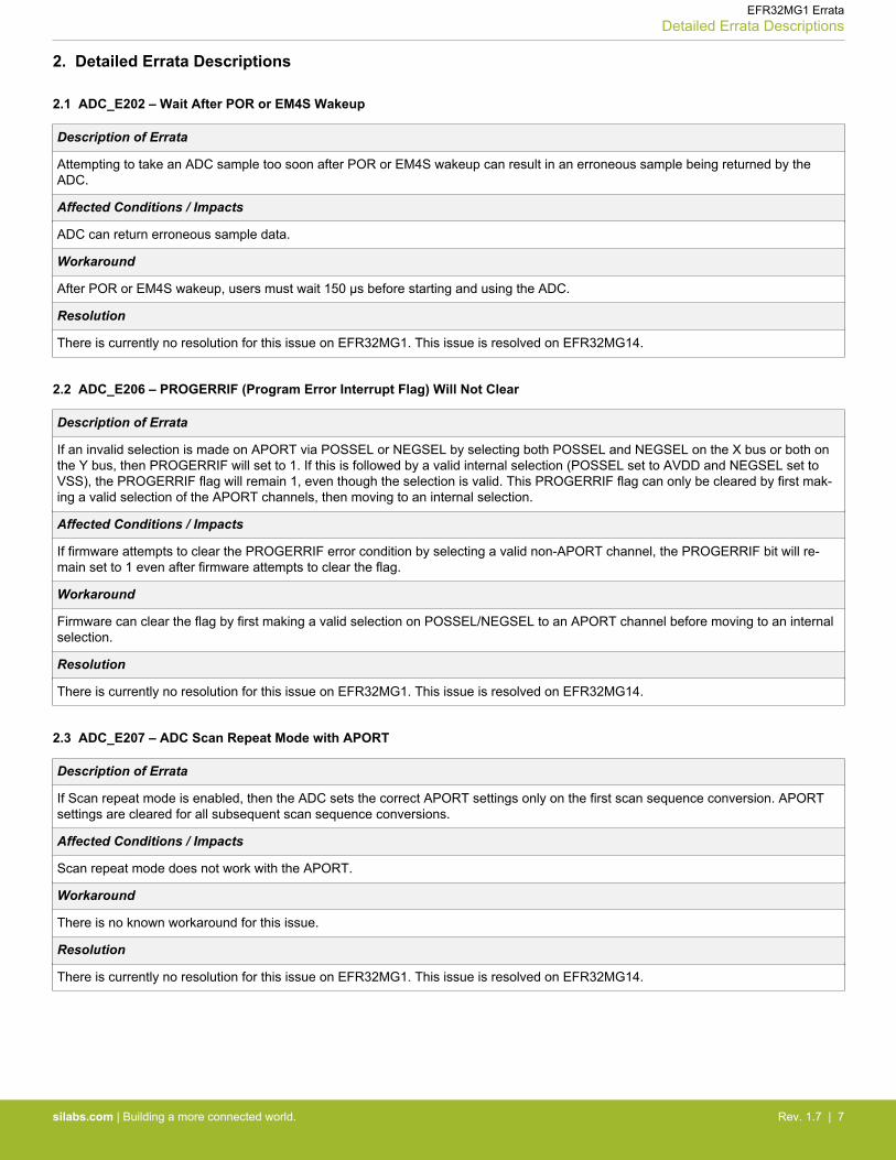
2.1 ADC_E202 – Wait After POR or EM4S Wakeup
Description of Errata
Attempting to take an ADC sample too soon after POR or EM4S wakeup can result in an erroneous sample being returned by theADC.
Affected Conditions / Impacts
ADC can return erroneous sample data.
Workaround
After POR or EM4S wakeup, users must wait 150 µs before starting and using the ADC.
Resolution
There is currently no resolution for this issue on EFR32MG1. This issue is resolved on EFR32MG14.
2.2 ADC_E206 – PROGERRIF (Program Error Interrupt Flag) Will Not Clear
Description of Errata
If an invalid selection is made on APORT via POSSEL or NEGSEL by selecting both POSSEL and NEGSEL on the X bus or both onthe Y bus, then PROGERRIF will set to 1. If this is followed by a valid internal selection (POSSEL set to AVDD and NEGSEL set toVSS), the PROGERRIF flag will remain 1, even though the selection is valid. This PROGERRIF flag can only be cleared by first mak-ing a valid selection of the APORT channels, then moving to an internal selection.
Affected Conditions / Impacts
If firmware attempts to clear the PROGERRIF error condition by selecting a valid non-APORT channel, the PROGERRIF bit will re-main set to 1 even after firmware attempts to clear the flag.
Workaround
Firmware can clear the flag by first making a valid selection on POSSEL/NEGSEL to an APORT channel before moving to an internalselection.
Resolution
There is currently no resolution for this issue on EFR32MG1. This issue is resolved on EFR32MG14.
2.3 ADC_E207 – ADC Scan Repeat Mode with APORT
Description of Errata
If Scan repeat mode is enabled, then the ADC sets the correct APORT settings only on the first scan sequence conversion. APORTsettings are cleared for all subsequent scan sequence conversions.
Affected Conditions / Impacts
Scan repeat mode does not work with the APORT.
Workaround
There is no known workaround for this issue.
Resolution
There is currently no resolution for this issue on EFR32MG1. This issue is resolved on EFR32MG14.
EFR32MG1 ErrataDetailed Errata Descriptions
silabs.com | Building a more connected world. Rev. 1.7 | 7
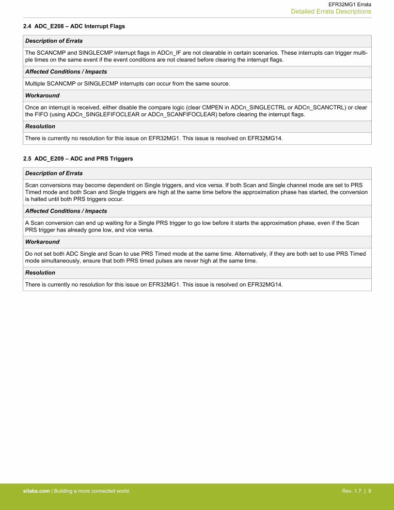
2.4 ADC_E208 – ADC Interrupt Flags
Description of Errata
The SCANCMP and SINGLECMP interrupt flags in ADCn_IF are not clearable in certain scenarios. These interrupts can trigger multi-ple times on the same event if the event conditions are not cleared before clearing the interrupt flags.
Affected Conditions / Impacts
Multiple SCANCMP or SINGLECMP interrupts can occur from the same source.
Workaround
Once an interrupt is received, either disable the compare logic (clear CMPEN in ADCn_SINGLECTRL or ADCn_SCANCTRL) or clearthe FIFO (using ADCn_SINGLEFIFOCLEAR or ADCn_SCANFIFOCLEAR) before clearing the interrupt flags.
Resolution
There is currently no resolution for this issue on EFR32MG1. This issue is resolved on EFR32MG14.
2.5 ADC_E209 – ADC and PRS Triggers
Description of Errata
Scan conversions may become dependent on Single triggers, and vice versa. If both Scan and Single channel mode are set to PRSTimed mode and both Scan and Single triggers are high at the same time before the approximation phase has started, the conversionis halted until both PRS triggers occur.
Affected Conditions / Impacts
A Scan conversion can end up waiting for a Single PRS trigger to go low before it starts the approximation phase, even if the ScanPRS trigger has already gone low, and vice versa.
Workaround
Do not set both ADC Single and Scan to use PRS Timed mode at the same time. Alternatively, if they are both set to use PRS Timedmode simultaneously, ensure that both PRS timed pulses are never high at the same time.
Resolution
There is currently no resolution for this issue on EFR32MG1. This issue is resolved on EFR32MG14.
EFR32MG1 ErrataDetailed Errata Descriptions
silabs.com | Building a more connected world. Rev. 1.7 | 8
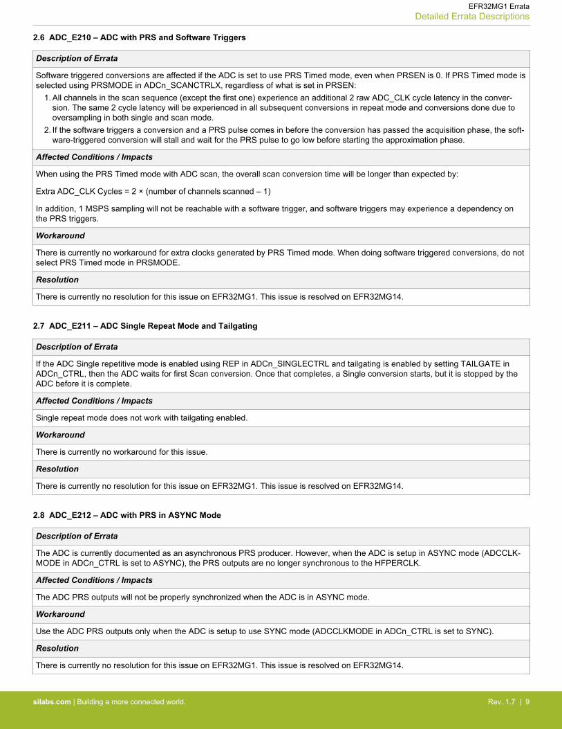
2.6 ADC_E210 – ADC with PRS and Software Triggers
Description of Errata
Software triggered conversions are affected if the ADC is set to use PRS Timed mode, even when PRSEN is 0. If PRS Timed mode isselected using PRSMODE in ADCn_SCANCTRLX, regardless of what is set in PRSEN:
1. All channels in the scan sequence (except the first one) experience an additional 2 raw ADC_CLK cycle latency in the conver-sion. The same 2 cycle latency will be experienced in all subsequent conversions in repeat mode and conversions done due tooversampling in both single and scan mode.
2. If the software triggers a conversion and a PRS pulse comes in before the conversion has passed the acquisition phase, the soft-ware-triggered conversion will stall and wait for the PRS pulse to go low before starting the approximation phase.
Affected Conditions / Impacts
When using the PRS Timed mode with ADC scan, the overall scan conversion time will be longer than expected by:
Extra ADC_CLK Cycles = 2 × (number of channels scanned – 1)
In addition, 1 MSPS sampling will not be reachable with a software trigger, and software triggers may experience a dependency onthe PRS triggers.
Workaround
There is currently no workaround for extra clocks generated by PRS Timed mode. When doing software triggered conversions, do notselect PRS Timed mode in PRSMODE.
Resolution
There is currently no resolution for this issue on EFR32MG1. This issue is resolved on EFR32MG14.
2.7 ADC_E211 – ADC Single Repeat Mode and Tailgating
Description of Errata
If the ADC Single repetitive mode is enabled using REP in ADCn_SINGLECTRL and tailgating is enabled by setting TAILGATE inADCn_CTRL, then the ADC waits for first Scan conversion. Once that completes, a Single conversion starts, but it is stopped by theADC before it is complete.
Affected Conditions / Impacts
Single repeat mode does not work with tailgating enabled.
Workaround
There is currently no workaround for this issue.
Resolution
There is currently no resolution for this issue on EFR32MG1. This issue is resolved on EFR32MG14.
2.8 ADC_E212 – ADC with PRS in ASYNC Mode
Description of Errata
The ADC is currently documented as an asynchronous PRS producer. However, when the ADC is setup in ASYNC mode (ADCCLK-MODE in ADCn_CTRL is set to ASYNC), the PRS outputs are no longer synchronous to the HFPERCLK.
Affected Conditions / Impacts
The ADC PRS outputs will not be properly synchronized when the ADC is in ASYNC mode.
Workaround
Use the ADC PRS outputs only when the ADC is setup to use SYNC mode (ADCCLKMODE in ADCn_CTRL is set to SYNC).
Resolution
There is currently no resolution for this issue on EFR32MG1. This issue is resolved on EFR32MG14.
EFR32MG1 ErrataDetailed Errata Descriptions
silabs.com | Building a more connected world. Rev. 1.7 | 9
2.9 ADC_E213 – ADC KEEPINSLOWACC Mode
Description of Errata
When WARMUP-MODE in ADCn_CTRL is set to KEEPINSLOWACC, the ADC does not track the input voltage. Also, the ADC keepsthe input muxes closed even during channel switching, making it not recommended to operate the ADC in KEEPINSLOWACC mode.
Affected Conditions / Impacts
KEEPINSLOWACC warmup mode does not function properly.
Workaround
There is currently no workaround for this issue.
Resolution
There is currently no resolution for this issue.
2.10 ADC_E214 – Using ADC CHCONMODE with PRS
Description of Errata
When CHCONMODE in ADCn_CTRL is set MAXRESP, the ADC does not work with PRS Timed mode.
Affected Conditions / Impacts
If the PRS pulse is longer than the ADC acquisition time, the input mux select lines are switched during the acquisition phase, causingthe results to no longer be usable.
Workaround
PRS Timed mode should not be used with CHCONMODE in ADCn_CTRL set to MAXRESP.
Resolution
There is currently no resolution for this issue on EFR32MG1. This issue is resolved on EFR32MG14.
2.11 ADC_E215 – ADC CHCONMODE Set to MAXRESP Causes Extra Latency
Description of Errata
Setting CHCONMODE in ADCn_CTRL to MAXRESP introduces 7 extra raw ADC_CLK cycles of latency between scan conversions ina sequence.
Affected Conditions / Impacts
The 7 raw ADC_CLK cycles of extra latency impacts the time the sample is taken.
Workaround
Use CHCONMODE set to MAXSETTLE in order to avoid the extra latency.
Resolution
There is currently no resolution for this issue on EFR32MG1. This issue is resolved on EFR32MG14.
EFR32MG1 ErrataDetailed Errata Descriptions
silabs.com | Building a more connected world. Rev. 1.7 | 10
2.12 ADC_E216 – ADC Conversion Start Delay
Description of Errata
If CONVSTARTDELAYEN in both SINGLECTRLX and SCANCTRLX registers are set to 1, the ADC will look at CONVSTARTDELAYvalue set in SINGLECTRLX register regardless of the conversion type (SCAN or SINGLE). If a SCAN conversion is triggered in thisscenario, the conversion will be delayed for the value specified in SINGLECTRLX. In all other cases, the ADC behaves as expected.
Affected Conditions / Impacts
Enabling both SINGLE and SCAN conversion start delay can result in unexpected behavior if the delay selection in the SINGLE andSCAN registers is different.
Workaround
If different CONVSTARTDELAY values are desired for SCAN and SINGLE, do not keep both SINGLE CONVSTARTDELAY andSCAN CONVSTARTDELAY enabled at the same time.
Resolution
There is currently no resolution for this issue on EFR32MG1. This issue is resolved on EFR32MG14.
2.13 ADC_E217 – Multiple CLK Mode Switches
Description of Errata
This issue can be encountered if the ADC clock (CLK) mode switches between asynchronous (ASYNC) and synchronous (SYNC)while data is being read. Specifically, this issue can occur if ADC operates in ASYNC mode with converted data being read, thensome conversions are done in SYNC mode before being switched back to ASYNC mode again. FIFOCOUNT may show the wrongvalue when read in ASYNC mode after the last clock mode switch. Note that the recommended procedure for switching CLK modesshould always be followed.
Affected Conditions / Impacts
An unexpected value may be read from FIFOCOUNT registers.
Workaround
When switching from SYNC to ASYNC mode more than once, clear the FIFOs using FIFOCLEAR before and after the CLK modeswitch.
Resolution
There is currently no resolution for this issue on EFR32MG1. This issue is resolved on EFR32MG14.
2.14 ADC_E218 – SINGLEACT and SCANACT Status Flags Delayed
Description of Errata
Once the SINGELSTART/SCANSTART commands are issued, it takes a few cycles before the ADC SINGLEACT/SCANACT statusflags are set.
Affected Conditions / Impacts
The status flags cannot be checked right after the conversion start commands are issued.
Workaround
Firmware that wants to check when a conversion has started after sending a software trigger will need to wait until the correspondingstatus flag (SINGELACT/SCANACT) goes high before proceeding.
Resolution
There is currently no resolution for this issue on EFR32MG1. This issue is resolved on EFR32MG14.
EFR32MG1 ErrataDetailed Errata Descriptions
silabs.com | Building a more connected world. Rev. 1.7 | 11

2.15 ADC_E219 – STOP Command Causing FIFO Corruption
Description of Errata
If a single or scan conversion is running and a software STOP command is issued, the conversion should stop immediately and theresult should be be discarded (no FIFO updates should happen). Currently in the ADC, if a single (scan) conversion is stopped by asoftware STOP command and there is a scan (single) conversion pending, then the conversion will incorrectly continue and the resultwill be used to update the FIFO.
Affected Conditions / Impacts
Issuing the STOP command can have two different effects.
If the command is sent during a conversion, the effect will be immediate if no other conversion is pending. The immediate effectmeans stopping the on-going conversion and discarding the current sample.
If the command is sent during a conversion, the on-going conversion will finish, and the current sample will be saved into the corre-sponding FIFO. This means that the single conversion will fully finish (regardless of the ADC mode, e.g. if in the oversampling mode,the full oversampling will be executed, or if in the repetition mode, the current conversion will finish and then the repetition mode forsingle will be disabled) and that the scan conversion will fully finish conversion of the current channel, but it will not finish the wholescan sequence (regardless of the ADC mode). In the last case, the scan FIFO will be updated with the data from channels convertedso far.
Workaround
If using the STOP command, the effect will be immediate if no scan triggers were pending during the single conversion and vice ver-sa.
Resolution
There is currently no resolution for this issue on EFR32MG1. This issue is resolved on EFR32MG14.
2.16 ADC_E220 – AUXHFRCO in ASYNC mode with ASYNC CLK in ASNEEDED mode
Description of Errata
ADC sampling in the ASYNC ASNEEDED mode when running from the AUXHFRCO can temporarily upset voltage references usedin certain analog components. This issue effects the BOD trip point, DCDC voltage accuracy, ACMP reference accuracy, IDAC outputcurrent accuracy, and low voltage digital supply voltage accuracy.
Affected Conditions / Impacts
If the ADC is being used in ASYNC mode with AUXHFRCO, ASYNC CLK cannot be used in ASNEEDED mode.
Workaround
If the ADC is being used in ASYNC mode with AUXHFRCO, ASYNC CLK must be set to ALWAYSON mode.
Resolution
There is currently no resolution for this issue on EFR32MG1. This issue is resolved on EFR32MG14.
EFR32MG1 ErrataDetailed Errata Descriptions
silabs.com | Building a more connected world. Rev. 1.7 | 12
2.17 ADC_E221 – ADC Temperature Sensor Must be Used in LOWACC Mode
Description of Errata
The ADC temperature sensor used in HIGHACC mode can temporarily upset voltage references used in certain analog components.This issue effects the BOD trip point, DCDC voltage accuracy, ACMP reference accuracy, IDAC output current accuracy, and low volt-age digital supply voltage accuracy.
Affected Conditions / Impacts
If the ADC is being used to take a reading from its internal temperature sensor, ADCn_BIASPROG.GPBIASACC = 0 cannot be used.
Workaround
Use ADCn_BIASPROG.GPBIASACC = 1 when taking temperature measurements.
Resolution
There is currently no resolution for this issue on EFR32MG1. This issue is resolved on EFR32MG14.
2.18 ADC_E222 – ADC EM2 Wakeup on a Comparator Match Disables EM2 Entry
Description of Errata
If the ADC wakes up the system from EM2 on a comparator flag match (CMPEN must be set in SINGLECTRL/SCANCTRL), thewake-up handler will not be able to clear this EM2 wakeup request. This results in the core immediately exiting EM2 on subsequentEM2 entry.
Affected Conditions / Impacts
Systems using the ADC comparator flag match may not be able to enter EM2.
Workaround
To clear the wakeup request, the wakeup handler must do one of the following:
• Disable CMPEN in the SINGLECTRL/SCANCTRL register.• Reset the ADC FIFO.• Continue performing conversions until an incoming conversion does not pass the CMP threshold set in CMPTHR.
Once one of these conditions has been met, the comparator can be re-enabled (if it was disabled) and the core can enter EM2.
Resolution
There is currently no resolution for this issue on EFR32MG1. This issue is resolved on EFR32MG14.
EFR32MG1 ErrataDetailed Errata Descriptions
silabs.com | Building a more connected world. Rev. 1.7 | 13
2.19 ADC_E223 – Delayed ADC Conversion or Warmup Start
Description of Errata
When a new conversion trigger is received from PRS or a software start, the ADC is expected to either:
1. Immediately start warmup (if ADCn_CTRL_WARMUPMODE is set to NORMAL, KEEPINSTANDBY, or KEEPINSLOWACC).2. Immediately start the conversion (if in KEEPADCWARM warmup mode).
This expected behavior does not occur if the ADC prescaler (ADCn_CTRL_PRESC) is set to a non-zero value, as the start of the ADCwarmup or conversion gets delayed by the number of ADC clock cycles specified by the PRESC field.
Affected Conditions / Impacts
Systems using the ADC clock prescaler will see a delay after a start-of-conversion or start-of-warmup trigger and the actual conver-sion or warmup sequence.
Workaround
For systems that cannot tolerate a delay between the start-of-conversion and actual conversion or before ADC warmup, setADCn_CTRL_PRESC to 0 and use the prescalars in the CMU to prescale the incoming ADC_CLK.
Resolution
There is currently no resolution for this issue on EFR32MG1. This issue is resolved on EFR32MG14.
2.20 ADC_E224 – ADC Warm-Up Ready Can Cause ACMP to Not Function
Description of Errata
The ACMP module uses use the warm up timing module in the ADC to determine when the peripherals are ready for use. However, ifthe ADC is enabled first, this timing module can fail to properly handshake with a low probability, causing the ACMP module to neverfinish warming up. The ADC is not affected by this issue and will always be available after it is enabled.
Affected Conditions / Impacts
Systems using the ACMP module in conjunction with the ADC can see intermittent failures where these modules do not operate.
Workaround
To work around this issue, enable the ACMP module before enabling the ADC. This will ensure the handshaking logic between theADC and other modules functions correctly.
Resolution
There is currently no resolution for this issue on EFR32MG1. This issue is resolved on EFR32MG14.
EFR32MG1 ErrataDetailed Errata Descriptions
silabs.com | Building a more connected world. Rev. 1.7 | 14
2.21 ADC_E226 – SCANSTOP Does Not Immediately Stop the Ongoing Sample
Description of Errata
The stop behavior of conversions differs between scan mode (SCANSTOP in ADCn_CMD) or single conversion mode (SINGLESTOPin ADCn_CMD).
1. If the SINGLESTOP command is sent during a single conversion, the effect will be immediate if no other conversion is pending. Inthis case, the ADC immediately stops the on-going conversion and discards the current sample.
2. If the SCANSTOP command is sent during a scan conversion, the on-going conversion will finish and the current sample will besaved into the corresponding FIFO. If oversampling mode is enabled (RES in ADCn_SCANCTRL set to OVS), the full oversam-pling will be completed for this sample. If in repetition mode (REP in ADCn_SCANCTRL set to 1), the current conversion will fin-ish and then the repetition mode for the single channel will be disabled. Once the current conversion completes, the rest of thescan sequence aborts.
Affected Conditions / Impacts
Systems issuing a SCANSTOP command to the ADC may see an additional conversion in scan mode.
Workaround
There is currently no workaround for this issue.
Resolution
There is currently no resolution for this issue on EFR32MG1. This issue is resolved on EFR32MG14.
2.22 ADC_E227 – New Conversion Triggers Cause Jitter to the Ongoing Conversions
Description of Errata
In some cases, an ADC conversion can take one conversion clock longer in the worst case if a new conversion trigger occurs whileanother conversion is ongoing. The results of the conversion are unaffected.
Affected Conditions / Impacts
Systems issuing conversion triggers while conversions are ongoing may see slightly longer conversion times.
Workaround
There is currently no workaround for this issue.
Resolution
There is currently no resolution for this issue on EFR32MG1. This issue is resolved on EFR32MG14.
2.23 CORE_E201 – SYSTICK and an External Clock
Description of Errata
The core allows two different clock sources for the SysTick counter. The first one is the core free-running clock, which operates cor-rectly. The second source uses the 32 kHz from the RTCC. This pulse width of this clock is not wide enough, which results in missedSysTick counts.
Affected Conditions / Impacts
Firmware should not use the external clock source for the SysTick counter.
Workaround
Use the core free-running clock for the SysTick, which is the default selection.
Resolution
There is currently no resolution for this issue on EFR32MG1. This issue is resolved on EFR32MG14.
EFR32MG1 ErrataDetailed Errata Descriptions
silabs.com | Building a more connected world. Rev. 1.7 | 15
2.24 CRYPTO_E201 — Full CRYPTO Not Available in All Value Devices
Description of Errata
The device documentation states that all devices support full CRYPTO capability. However, some Value devices (e.g. EFR32xG1V)before a date code of 1638 (September 19, 2016) will not have full CRYPTO capability. Instead, these affected devices will only haveAES enabled.
Affected Conditions / Impacts
Some Value devices before a date code of 1638 (September 19, 2016) will not have full CRYPTO capability.
Workaround
There is currently no workaround for this issue.
Resolution
Revision C Value devices after date code 1638 (September 19, 2016) will have full CRYPTO capability.
2.25 DBG_E201 – AUXHFRCO Debug Limitations
Description of Errata
The AUXHFRCO is the default debug clock, set by DBG in CMU_DBGCLKSEL. Using AUXHFRCO as the debug clock while enteringEM2 has the potential of corrupting the system, causing some registers in the TPIU to not retain their value.
Affected Conditions / Impacts
Firmware should not use the AUXHFRCO as the debug clock while entering EM2.
Workaround
When using AUXHFRCO as the debug clock, it must be stopped before entering the EM2 power mode. Alternatively, select anotherclock source as the debug clock before entering EM2.
Resolution
There is currently no resolution for this issue on EFR32MG1. This issue is resolved on EFR32MG14.
2.26 DBG_E202 – Debug Access to ADC and LEUART not Functioning as Intended
Description of Errata
ADC and LEUART registers that have a side-effect during a read access (i.e., LEUART_RXDATA or other registers that pop dataread) continue to execute triggered actions when an attached debugger is performing read accesses. The intended behavior is to haltexecution of pop actions when a debugger is attached.
Affected Conditions / Impacts
Some ADC and LEAURT registers will pop data from their respective buffers on read accesses from the debugger.
Workaround
The user needs to be aware that while debugging, reads via the debugger have the same affect as reads by the CPU during normalmode for these registers. To avoid the debugger triggering a data pop from the buffer, the user should avoid setting a memory windowover the actionable register(s), as the reads to fetch the data for the debugger memory view would trigger the data pop from the buf-fer.
Resolution
There is currently no resolution for this issue on EFR32MG1. This issue is resolved on EFR32MG14.
EFR32MG1 ErrataDetailed Errata Descriptions
silabs.com | Building a more connected world. Rev. 1.7 | 16
2.27 DBG_E204 – Debug Recovery with JTAG Does Not Work
Description of Errata
The debug recovery algorithm of holding down pin reset, issuing a System Bus Stall AAP instruction, and releasing the reset pin doesnot work when using the JTAG debug interface. When using the JTAG debug interface, the core will continue to execute code as soonas the reset pin is released.
Affected Conditions / Impacts
The debug recovery sequence will not work when using the JTAG debug interface.
Workaround
Use the Serial Wire debug interface to implement the debug recovery sequence.
Resolution
There is currently no resolution for this issue.
2.28 DCDC_E202 – Regulated DCDC Output Can Dip on EM2 Entry
Description of Errata
The regulated output on DVDD, when using the DCDC, can dip up to 4% during EM2 entry.
Affected Conditions / Impacts
External components operating from DVDD, when regulated by the DCDC, may suffer a depressed supply by up to 4%, which canlast approximately 1 ms. Operation of the device is not affected when this occurs.
Workaround
There is currently no workaround for this issue.
Resolution
There is currently no resolution for this issue on EFR32MG1. This issue is resolved on EFR32MG14.
2.29 DCDC_E203 – Regulated DCDC Output Can Dip on EM2 Entry if not in LN Mode
Description of Errata
The regulated output on DVDD, when using the DCDC, can dip up to approximately 9% during EM2 entry if the DCDC has not com-pleted a transition into LN mode. Note that if a switch to LN mode completes prior to entry to EM2, the DCDC can exhibit the behaviordescribed in DCDC_E202.
Affected Conditions / Impacts
External components operating from DVDD, when regulated by the DCDC, may suffer a depressed supply by up to approximately 9%,which can last approximately 1 ms. A BOD reset of the device is possible, but unlikely.
Workaround
Firmware should wait to see LNRUNNING set after initiating a transition of the DCDC into LN mode, before attempting to enter EM2.This workaround is included in v5.0.0 or later of the Gecko SDK.
Resolution
There is currently no resolution for this issue on EFR32MG1. This issue is resolved on EFR32MG14.
EFR32MG1 ErrataDetailed Errata Descriptions
silabs.com | Building a more connected world. Rev. 1.7 | 17
2.30 DCDC_E205 – Delay Required after Enabling the DC-DC Before Entering EM2/3/4H
Description of Errata
The DC-DC hardware state machine may malfunction if the device transitions to EM2, EM3, or EM4H before the DC-DC starts run-ning Low Noise mode after being enabled.
Affected Conditions / Impacts
Systems using the DC-DC converter should wait ~300 µs until the LNRUNNING status bit in the DCDCSTATUS register is set beforetransitioning to EM2, EM3, or EM4H after enabling the DC-DC converter.
Workaround
Firmware should wait for the DCDCLNRUNNING bit to be set in the EMU_IF register before transitioning to EM2, EM3, or EM4H afterenabling the DC-DC converter.
This workaround is included in v5.1.0 or later of the Gecko SDK.
Resolution
There is currently no resolution for this issue on EFR32MG1. This issue is resolved on EFR32MG14.
EFR32MG1 ErrataDetailed Errata Descriptions
silabs.com | Building a more connected world. Rev. 1.7 | 18
2.31 DCDC_E206 – Reset During Radio Operation With DC-DC Results in DVDD Brown Out
Description of Errata
During radio operation with the DC-DC enabled, the protocol stacks enable radio interference minimization features which change thesource of the DC-DC clock to reduce the impact of the DC-DC switching frequency on the radio. When a soft reset occurs (e.g., froma Pin or WDOG), the minimal interference DC-DC clock stops, causing the DC-DC to stop switching and charging up the output volt-age, which results in a brown-out on the DVDD supply. The device then resets to its default start-up DC-DC configuration with thebypass switch enabled (i.e., DVDD=VREGVDD), and execution continues.
As a result of this sequence, the original reset cause indicated in the RMU_RSTCAUSE register will be masked by the brown-outreset (DVDDBOD) flag.
Affected Conditions / Impacts
Systems using the radio and DC-DC converter that are expecting to read valid results from the RMU_RSTCAUSE register forEM4RST, WDOGRST, SYSREQRST, LOCKUPRST, or EXTRST resets will see a brown-out reset event, instead.
Workaround
To prevent the DVDD brown-out, firmware can immediately enable the bypass switch early in code execution. For example, in the SystemInit() function in system_efr32xg1b.c, add the following lines of code:
BUS_RegBitWrite(&EMU->DCDCCLIMCTRL, _EMU_DCDCCLIMCTRL_BYPLIMEN_SHIFT, 1);EMU->DCDCCTRL = (EMU->DCDCCTRL & ~_EMU_DCDCCTRL_DCDCMODE_MASK) | emuDcdcMode_Bypass;*(volatile uint32_t *)(0x400E3074) &= ~(0x1UL << 0);*(volatile uint32_t *)(0x400E3060) &= ~(0x1UL << 28);
Then, add the following line at the beginning of main():
BUS_RegBitWrite(&EMU->DCDCCLIMCTRL, _EMU_DCDCCLIMCTRL_BYPLIMEN_SHIFT, 0);
This will disable the bypass current limit, which was enabled in the first line of the SystemInit() sequence. This limit prevents exces-sive current through the bypass when transitioning across large steps between DVDD and VDD, but consumes ~10uA of current thatis no longer necessary once DVDD has ascended to near VDD.
Additional information on the workaround and examples provided is available from the following KB article URL:
http://community.silabs.com/t5/Mesh-Knowledge-Base/DCDC-E206-Reset-During-Radio-Operation-With-DC-DC-Results-in/ta-p/193802
Note: This workaround may not suffice for a pin reset initiated by a button press, which may be on the order of 50-300 ms. Becausethe device won’t come out of reset to execute the workaround until the reset button is released, the DVDD supply will discharge duringthe entire duration the button is pressed, which will likely result in a DVDD brown-out.
Resolution
There is currently no resolution for this issue on EFR32MG1. This issue is resolved on EFR32MG14.
EFR32MG1 ErrataDetailed Errata Descriptions
silabs.com | Building a more connected world. Rev. 1.7 | 19

2.32 EFR_E201 – Bit Access Not Supported for Low Energy Peripherals
Description of Errata
Bit set and clear operations do not work properly for Low Energy Peripherals including WDOG, PCNT0, LEUART0, LETIMER0, andRTCC.
Affected Conditions / Impacts
To implement bit set or bit clear operations with Low Energy Peripherals, firmware must execute a read-modify-write operation ad-dress on the peripheral's registers.
Workaround
To implement bit set or bit clear operations with Low Energy Peripherals (WDOG, PCNT0, LEUART0, LETIMER0, and RTCC), firm-ware must execute a read-modify-write operation address on the peripheral's registers.
Resolution
There is currently no resolution for this issue on EFR32MG1. This issue is resolved on EFR32MG14.
2.33 EFR_E202 – Read-Clear Access for LETIMER0 and RTCC Interrupts
Description of Errata
The automatic read-clear mechanism for the LETIMER0 and RTCC modules does not actually clear the module interrupts.
Affected Conditions / Impacts
Firmware must be written to manually clear the interrupts for the LETIMER0 and RTCC modules.
Workaround
Firmware must read the LETIMER0 and RTCC interrupts using the module IFS register and clear the interrupts manually by writing tothe module IFC register.
Resolution
There is currently no resolution for this issue on EFR32MG1. This issue is resolved on EFR32MG14.
2.34 EMU_E201 – High Temperature Operation
Description of Errata
The performance of analog peripherals at high temperatures (above 50 °C) may change over time. Firmware should periodically ad-just the calibration of the analog peripherals to compensate for this behavior.
This issue affects the BOD trip point, dc-dc output voltage accuracy, ACMP reference accuracy, and IDAC output current accuracy inEM2 through EM4H power modes. This does not affect operation of these peripherals in the EM0, EM1, or EM4S power modes.
Affected Conditions / Impacts
The performance of analog peripherals at high temperatures may change over time.
Workaround
The TEMPDRV module in emdrv addresses this issue and should be included in application firmware. This module is automaticallyincluded for systems using Silicon Labs software stacks. For systems not using a Silicon Labs stack (i.e., writing code from scratch orusing software examples as a starting point), firmware should include the TEMPDRV module and call the TEMPDRV_Init() function toimprove high temperature operation (above 50 °C). The module documentation can be found in Simplicity Studio and contains moreinformation about the firmware solution.
See AN1027: EFR32xG1 and EFM32PG1/JG1 High-Temperature Operation for more information.
Resolution
There is currently no resolution for this issue on EFR32MG1. This issue is resolved on EFR32MG14.
EFR32MG1 ErrataDetailed Errata Descriptions
silabs.com | Building a more connected world. Rev. 1.7 | 20
2.35 EMU_E204 – Restrictions Writing TEMPHIGH and TEMPLOW
Description of Errata
Writing TEMPHIGH and TEMPLOW in EMU_TEMPLIMITS at certain times can cause erroneous interrupts to occur.
Affected Conditions / Impacts
Writing to TEMPHIGH or TEMPLOW in EMU_TEMPLIMITS at any time may cause the TEMPHIGH and TEMPLOW interrupt flags inEMU_IF to trigger incorrectly.
Workaround
Firmware should only write TEMPHIGH and TEMPLOW within 250 ms of receiving a TEMPLOW, TEMPHIGH, or TEMP interrupt.
Resolution
There is currently no resolution for this issue on EFR32MG1. This issue is resolved on EFR32MG14.
2.36 EMU_E205 – Restrictions Reading TEMP
Description of Errata
Reads of TEMP in EMU_TEMP may not always return the correct value.
Affected Conditions / Impacts
Reading TEMP in EMU_TEMP at any time may read an incorrect value.
Workaround
Firmware should restrict its reading of TEMP to the following scenarios:1. Read the TEMP field multiple times until the same value is returned in two consecutive reads.2. Read TEMP within 250 ms of receiving a TEMPLOW, TEMPHIGH, or TEMP interrupt.
Resolution
There is currently no resolution for this issue on EFR32MG1. This issue is resolved on EFR32MG14.
2.37 EMU_E207 – GPIO State can be Lost During EM4 Recovery
Description of Errata
Firmware can configure the I/O state to be retained when exiting EM4 by setting EM4IORETMODE in EMU_EM4CTRL. The desiredbehavior is that firmware can restore the state of the I/Os in EM0 after exit from EM4 via reset while the I/O state is maintained. It ispossible for a GPIO saving a non-5 V tolerant (non-OVT) configuration pull-down configuration to lose the pull-down state if 5 V (OVT)tolerance is disabled using GPIO_Px_OVTDIS before restoring the pull-down configuration.
Affected Conditions / Impacts
Restoring the GPIO after an EM4 wakeup improperly can result in the I/O pull-down configuration being lost.
Workaround
The loss of the pull-down state can be avoided by re-enabling the pull-down before disabling the Over Voltage Tolerance for a GPIOusing GPIO_Px_OVTDIS.
Resolution
There is currently no resolution for this issue on EFR32MG1. This issue is resolved on EFR32MG14.
EFR32MG1 ErrataDetailed Errata Descriptions
silabs.com | Building a more connected world. Rev. 1.7 | 21

2.38 EMU_E208 – Occasional Full Reset After Exiting EM4H
Description of Errata
Exiting EM4H may occasionally cause a full reset causing loss of RTCC counters and result in longer wakeup times on the order ofpower-on wakeup times.
Affected Conditions / Impacts
When waking up from EM4H, the system does not wait long enough for the BODs to settle before enabling it as a reset source. Evenif the power is stable on DECOUPLE, AVDD, or DVDD, the part may see a BOD reset. The reset is reflected in the RESETCAUSEregister.
Workaround
The work around is to disable the BOD prior to EM4H entry. This work around is automatically implemented when the EMU_EnterEM4() function is called in the Gecko SDK (versions v4.4.0 or later).
__disable_irq();*(volatile uint32_t *)(EMU_BASE + 0x190) = 0x0000ADE8UL;*(volatile uint32_t *)(EMU_BASE + 0x198) |= (0x1UL << 7);
The BODs will automatically be enabled after EM4H wakeup, but disabling the BOD will also result in disabling the EM4BOD protec-tion. POR reset will still be valid. This work around is not needed for EM4S.
Note: Use the RMU_ResetCauseGet() function in emlib on EM4 wakeup to differentiate between a BOD reset and EM4RST. ForGecko SDK versions earlier than v5.0.0, the return value from RMU_ResetCauseGet() will be 0x0000001C (BOD reset) instead of0x00010000 (EM4RST) when waking up from EM4H.
Resolution
There is currently no resolution for this issue on EFR32MG1. This issue is resolved on EFR32MG14.
2.39 EMU_E209 – Potential EM2 Lock-up when using IDAC or the Debugger with the LDMA
Description of Errata
The device can lock up if firmware updates the IDAC output just before entering EM2 while the LDMA module is enabled. Similarly,the device can lock up if the Debugger is connected and the firmware enters EM2 while the LDMA module is enabled.
Affected Conditions / Impacts
Systems using the LDMA and IDAC or LDMA and Debugger may no longer function properly after attempting to enter EM2.
Workaround
Two workarounds exist:
1. If LDMA functionality in EM2 is not needed, firmware can disable the DMA via the CMU->HFBUSCLKEN* LDMA bit before enter-ing EM2.
2. If LDMA functionality in EM2 is needed, wait for the IDAC output to settle before entry into EM2 or disconnect the debugger be-fore entry into EM2.
Resolution
There is currently no resolution for this issue on EFR32MG1. This issue is resolved on EFR32MG14.
EFR32MG1 ErrataDetailed Errata Descriptions
silabs.com | Building a more connected world. Rev. 1.7 | 22
2.40 EMU_E210 – Potential Power-Down When Entering EM2
Description of Errata
On the rare occasion when the firmware starts a transition to EM2 while the EMU is updating its Temperature Sensor measurement,and then within a 300 ns window of entering EM2 the system is woken up to EM0 or EM1, the device’s internal power system can beerroneously disabled, powering down the device. When this occurs, the device will reset and will set the DECBOD flag in theRMU_RSTCAUSE register.
Affected Conditions / Impacts
Systems that do not use the emdrv TEMPDRV module may experience a power down on these very rare EM2 timing transitions.
Workaround
The TEMPDRV module in emdrv and CHIP_Init() (SDK version v5.0.0 or later) addresses this issue and should be included in appli-cation firmware. This module is automatically included for systems using Silicon Labs software stacks. For systems not using a SiliconLabs stack (i.e., writing code from scratch or using software examples as a starting point), firmware should include the TEMPDRVmodule and call the TEMPDRV_Init() and CHIP_Init() functions to prevent this issue from occurring. The module documentationcan be found in Simplicity Studio and contains more information about the firmware solution.
Resolution
There is currently no resolution for this issue on EFR32MG1. This issue is resolved on EFR32MG14.
2.41 EMU_E215 – Device May Brown Out After Energy Mode Transition
Description of Errata
The logic controlling the internal voltage regulator may rarely transition to an incorrect state after a transition to EM0 or EM1. Whenthis occurs, the device will reset and will set the DECBOD flag in the RMU_RSTCAUSE register.
Affected Conditions / Impacts
Systems that do not use the emdrv TEMPDRV module may experience a brown out on these rare EM0 or EM1 timing transitions.
Workaround
The TEMPDRV module in emdrv (SDK version v5.0.0 or later) addresses this issue and should be included in application firmware.This module is automatically included for systems using Silicon Labs software stacks. For systems not using a Silicon Labs stack (i.e.,writing code from scratch or using software examples as a starting point), firmware should include the TEMPDRV module and call theTEMPDRV_Init() function to prevent this issue from occurring. The module documentation can be found in Simplicity Studio and con-tains more information about the firmware solution.
Resolution
There is currently no resolution for this issue on EFR32MG1. This issue is resolved on EFR32MG14.
2.42 EMU_E216 – EM4H I/O Retention Cannot Be Disabled
Description of Errata
Even if I/O retention is disabled by clearing EM4IORETMODE in EMU_EM4CTRL to the DISABLE setting, the affected devices be-have as if I/O retention is configured as SWUNLATCH, meaning that the pin state is retained until software writes the EM4UNLATCHbit in the EMU_CMD register to remove retention.
Affected Conditions / Impacts
Systems that disable I/O retention mode may still see pins retain state until software writes the EM4UNLATCH bit in the EMU_CMDregister to remove retention.
Workaround
Software should always perform an I/O unlatch after exiting EM4H by calling the EMU_UnlatchPinRetention() function.
Resolution
There is currently no resolution for this issue on EFR32MG1. This issue is resolved on EFR32MG14.
EFR32MG1 ErrataDetailed Errata Descriptions
silabs.com | Building a more connected world. Rev. 1.7 | 23
2.43 IDAC_E201 – IDAC CURSTABLE Bit Not Reliable
Description of Errata
The IDAC CURSTABLE flag in IDAC_STATUS may erroneously report that the current output is stable.
Affected Conditions / Impacts
Systems using the IDAC should not rely on the CURSTABLE to determine if the output is stable.
Workaround
The CURSTABLE bit must not be used. Firmware must wait the minimum required IDAC settling time listed in the data sheet.
Resolution
There is currently no resolution for this issue on EFR32MG1. This issue is resolved on EFR32MG14.
2.44 I2C_E201 – I2C ABORT Command
Description of Errata
For on-going transactions, the ABORT command in I2Cn_CMD may cause the I2C module to lock up indefinitely if it is issued in themiddle of an I2C transaction.
Affected Conditions / Impacts
During on-going transactions, the ABORT command can cause the I2C receive module FSM to hang, locking up the I2C transactionindefinitely.
Workaround
The ABORT command should only be used after the I2C module is enabled in order to instruct the I2C module that the bus is IDLE.To use the ABORT command during a transaction, the I2C module should be disabled by clearing EN in I2Cn_CTRL.
Resolution
There is currently no resolution for this issue on EFR32MG1. This issue is resolved on EFR32MG14.
2.45 I2C_E206 – Slave Holds SCL Low After Losing Arbitration
Description of Errata
If, while transmitting data as a slave, arbitration is lost, SCL is unintentionally held low for an indefinite period of time.
Affected Conditions / Impacts
The winner of arbitration cannot use the bus because SCL is never released.
Workaround
If the I2C arbitration lost flag is asserted (I2C_IF_ARBLOST = 1) in slave mode (I2C_STATE_MASTER = 0), application softwareneeds to wait for at least one SCL high time and then issue the transmission abort command (set I2C_CMD_ABORT = 1), thus releas-ing SCL.
Resolution
There is currently no resolution for this issue.
EFR32MG1 ErrataDetailed Errata Descriptions
silabs.com | Building a more connected world. Rev. 1.7 | 24
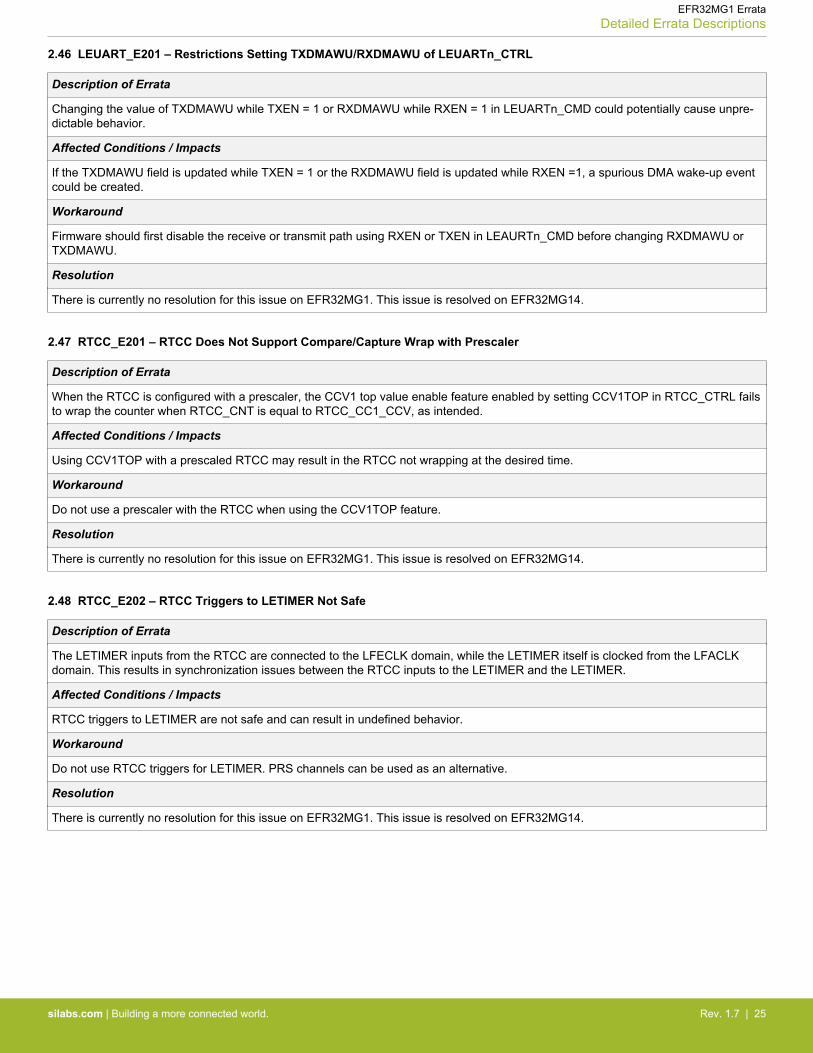
2.46 LEUART_E201 – Restrictions Setting TXDMAWU/RXDMAWU of LEUARTn_CTRL
Description of Errata
Changing the value of TXDMAWU while TXEN = 1 or RXDMAWU while RXEN = 1 in LEUARTn_CMD could potentially cause unpre-dictable behavior.
Affected Conditions / Impacts
If the TXDMAWU field is updated while TXEN = 1 or the RXDMAWU field is updated while RXEN =1, a spurious DMA wake-up eventcould be created.
Workaround
Firmware should first disable the receive or transmit path using RXEN or TXEN in LEAURTn_CMD before changing RXDMAWU orTXDMAWU.
Resolution
There is currently no resolution for this issue on EFR32MG1. This issue is resolved on EFR32MG14.
2.47 RTCC_E201 – RTCC Does Not Support Compare/Capture Wrap with Prescaler
Description of Errata
When the RTCC is configured with a prescaler, the CCV1 top value enable feature enabled by setting CCV1TOP in RTCC_CTRL failsto wrap the counter when RTCC_CNT is equal to RTCC_CC1_CCV, as intended.
Affected Conditions / Impacts
Using CCV1TOP with a prescaled RTCC may result in the RTCC not wrapping at the desired time.
Workaround
Do not use a prescaler with the RTCC when using the CCV1TOP feature.
Resolution
There is currently no resolution for this issue on EFR32MG1. This issue is resolved on EFR32MG14.
2.48 RTCC_E202 – RTCC Triggers to LETIMER Not Safe
Description of Errata
The LETIMER inputs from the RTCC are connected to the LFECLK domain, while the LETIMER itself is clocked from the LFACLKdomain. This results in synchronization issues between the RTCC inputs to the LETIMER and the LETIMER.
Affected Conditions / Impacts
RTCC triggers to LETIMER are not safe and can result in undefined behavior.
Workaround
Do not use RTCC triggers for LETIMER. PRS channels can be used as an alternative.
Resolution
There is currently no resolution for this issue on EFR32MG1. This issue is resolved on EFR32MG14.
EFR32MG1 ErrataDetailed Errata Descriptions
silabs.com | Building a more connected world. Rev. 1.7 | 25
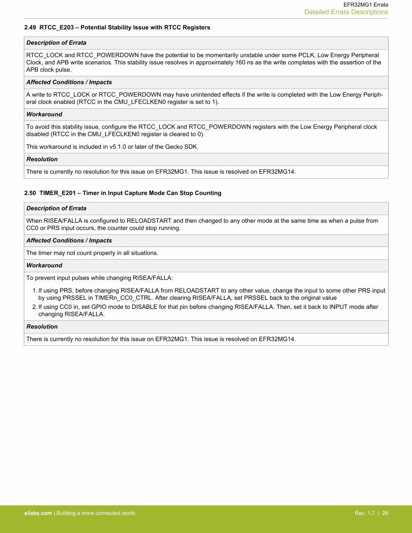
2.49 RTCC_E203 – Potential Stability Issue with RTCC Registers
Description of Errata
RTCC_LOCK and RTCC_POWERDOWN have the potential to be momentarily unstable under some PCLK, Low Energy PeripheralClock, and APB write scenarios. This stability issue resolves in approximately 160 ns as the write completes with the assertion of theAPB clock pulse.
Affected Conditions / Impacts
A write to RTCC_LOCK or RTCC_POWERDOWN may have unintended effects if the write is completed with the Low Energy Periph-eral clock enabled (RTCC in the CMU_LFECLKEN0 register is set to 1).
Workaround
To avoid this stability issue, configure the RTCC_LOCK and RTCC_POWERDOWN registers with the Low Energy Peripheral clockdisabled (RTCC in the CMU_LFECLKEN0 register is cleared to 0).
This workaround is included in v5.1.0 or later of the Gecko SDK.
Resolution
There is currently no resolution for this issue on EFR32MG1. This issue is resolved on EFR32MG14.
2.50 TIMER_E201 – Timer in Input Capture Mode Can Stop Counting
Description of Errata
When RISEA/FALLA is configured to RELOADSTART and then changed to any other mode at the same time as when a pulse fromCC0 or PRS input occurs, the counter could stop running.
Affected Conditions / Impacts
The timer may not count properly in all situations.
Workaround
To prevent input pulses while changing RISEA/FALLA:
1. If using PRS, before changing RISEA/FALLA from RELOADSTART to any other value, change the input to some other PRS inputby using PRSSEL in TIMERn_CC0_CTRL. After clearing RISEA/FALLA, set PRSSEL back to the original value
2. If using CC0 in, set GPIO mode to DISABLE for that pin before changing RISEA/FALLA. Then, set it back to INPUT mode afterchanging RISEA/FALLA.
Resolution
There is currently no resolution for this issue on EFR32MG1. This issue is resolved on EFR32MG14.
EFR32MG1 ErrataDetailed Errata Descriptions
silabs.com | Building a more connected world. Rev. 1.7 | 26
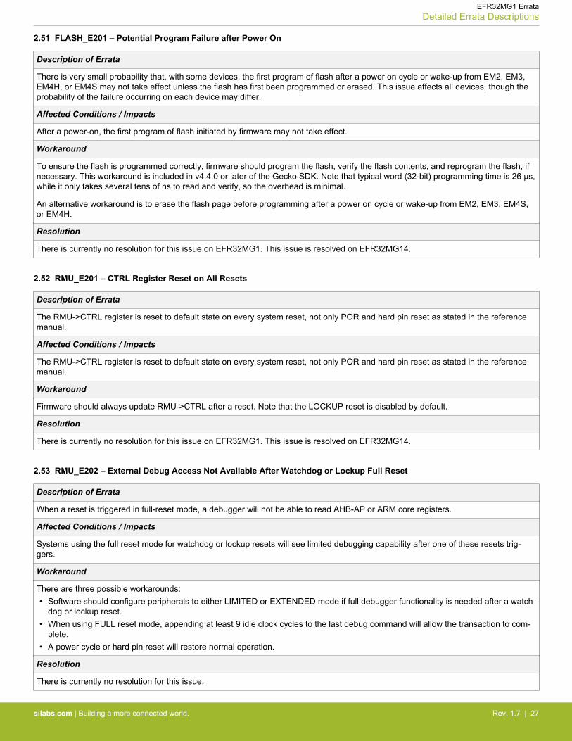
2.51 FLASH_E201 – Potential Program Failure after Power On
Description of Errata
There is very small probability that, with some devices, the first program of flash after a power on cycle or wake-up from EM2, EM3,EM4H, or EM4S may not take effect unless the flash has first been programmed or erased. This issue affects all devices, though theprobability of the failure occurring on each device may differ.
Affected Conditions / Impacts
After a power-on, the first program of flash initiated by firmware may not take effect.
Workaround
To ensure the flash is programmed correctly, firmware should program the flash, verify the flash contents, and reprogram the flash, ifnecessary. This workaround is included in v4.4.0 or later of the Gecko SDK. Note that typical word (32-bit) programming time is 26 µs,while it only takes several tens of ns to read and verify, so the overhead is minimal.
An alternative workaround is to erase the flash page before programming after a power on cycle or wake-up from EM2, EM3, EM4S,or EM4H.
Resolution
There is currently no resolution for this issue on EFR32MG1. This issue is resolved on EFR32MG14.
2.52 RMU_E201 – CTRL Register Reset on All Resets
Description of Errata
The RMU->CTRL register is reset to default state on every system reset, not only POR and hard pin reset as stated in the referencemanual.
Affected Conditions / Impacts
The RMU->CTRL register is reset to default state on every system reset, not only POR and hard pin reset as stated in the referencemanual.
Workaround
Firmware should always update RMU->CTRL after a reset. Note that the LOCKUP reset is disabled by default.
Resolution
There is currently no resolution for this issue on EFR32MG1. This issue is resolved on EFR32MG14.
2.53 RMU_E202 – External Debug Access Not Available After Watchdog or Lockup Full Reset
Description of Errata
When a reset is triggered in full-reset mode, a debugger will not be able to read AHB-AP or ARM core registers.
Affected Conditions / Impacts
Systems using the full reset mode for watchdog or lockup resets will see limited debugging capability after one of these resets trig-gers.
Workaround
There are three possible workarounds:• Software should configure peripherals to either LIMITED or EXTENDED mode if full debugger functionality is needed after a watch-
dog or lockup reset.• When using FULL reset mode, appending at least 9 idle clock cycles to the last debug command will allow the transaction to com-
plete.• A power cycle or hard pin reset will restore normal operation.
Resolution
There is currently no resolution for this issue.
EFR32MG1 ErrataDetailed Errata Descriptions
silabs.com | Building a more connected world. Rev. 1.7 | 27

2.54 USART_E202 — Incorrect 8-bit Timer Operation in Asynchronous Mode
Description of Errata
The 8-bit Timer logic that creates events within the USART works correctly in synchronous (USART) mode, but is not correct for asyn-chronous (UART) mode. As a result, it is not recommended to use the 8-bit Timer feature with asynchronous mode on affected devi-ces.
Affected Conditions / Impacts
Systems using the USART module in asynchronous (UART) mode should not use the 8-bit Timer feature.
Workaround
There is currently no workaround for this issue.
Resolution
There is currently no resolution for this issue on EFR32MG1. This issue is resolved on EFR32MG14.
EFR32MG1 ErrataDetailed Errata Descriptions
silabs.com | Building a more connected world. Rev. 1.7 | 28
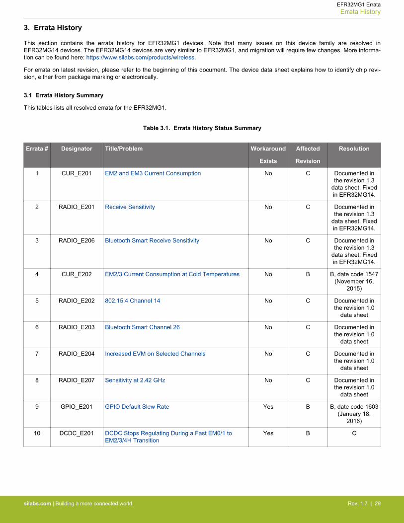
3. Errata History
This section contains the errata history for EFR32MG1 devices. Note that many issues on this device family are resolved inEFR32MG14 devices. The EFR32MG14 devices are very similar to EFR32MG1, and migration will require few changes. More informa-tion can be found here: https://www.silabs.com/products/wireless.
For errata on latest revision, please refer to the beginning of this document. The device data sheet explains how to identify chip revi-sion, either from package marking or electronically.
3.1 Errata History Summary
This tables lists all resolved errata for the EFR32MG1.
Table 3.1. Errata History Status Summary
Errata # Designator Title/Problem Workaround
Exists
Affected
Revision
Resolution
1 CUR_E201 EM2 and EM3 Current Consumption No C Documented inthe revision 1.3
data sheet. Fixedin EFR32MG14.
2 RADIO_E201 Receive Sensitivity No C Documented inthe revision 1.3
data sheet. Fixedin EFR32MG14.
3 RADIO_E206 Bluetooth Smart Receive Sensitivity No C Documented inthe revision 1.3
data sheet. Fixedin EFR32MG14.
4 CUR_E202 EM2/3 Current Consumption at Cold Temperatures No B B, date code 1547(November 16,
2015)
5 RADIO_E202 802.15.4 Channel 14 No C Documented inthe revision 1.0
data sheet
6 RADIO_E203 Bluetooth Smart Channel 26 No C Documented inthe revision 1.0
data sheet
7 RADIO_E204 Increased EVM on Selected Channels No C Documented inthe revision 1.0
data sheet
8 RADIO_E207 Sensitivity at 2.42 GHz No C Documented inthe revision 1.0
data sheet
9 GPIO_E201 GPIO Default Slew Rate Yes B B, date code 1603(January 18,
2016)
10 DCDC_E201 DCDC Stops Regulating During a Fast EM0/1 toEM2/3/4H Transition
Yes B C
EFR32MG1 ErrataErrata History
silabs.com | Building a more connected world. Rev. 1.7 | 29
3.2 Detailed Errata Descriptions
3.2.1 CUR_E201 – EM2 and EM3 Current Consumption
Description of Errata
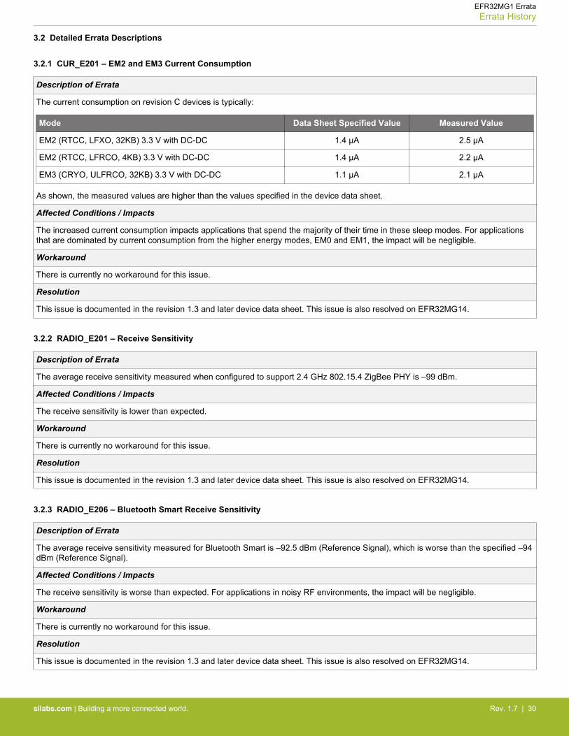
The current consumption on revision C devices is typically:
Mode Data Sheet Specified Value Measured Value
EM2 (RTCC, LFXO, 32KB) 3.3 V with DC-DC 1.4 µA 2.5 µA
EM2 (RTCC, LFRCO, 4KB) 3.3 V with DC-DC 1.4 µA 2.2 µA
EM3 (CRYO, ULFRCO, 32KB) 3.3 V with DC-DC 1.1 µA 2.1 µA
As shown, the measured values are higher than the values specified in the device data sheet.
Affected Conditions / Impacts
The increased current consumption impacts applications that spend the majority of their time in these sleep modes. For applicationsthat are dominated by current consumption from the higher energy modes, EM0 and EM1, the impact will be negligible.
Workaround
There is currently no workaround for this issue.
Resolution
This issue is documented in the revision 1.3 and later device data sheet. This issue is also resolved on EFR32MG14.
3.2.2 RADIO_E201 – Receive Sensitivity
Description of Errata
The average receive sensitivity measured when configured to support 2.4 GHz 802.15.4 ZigBee PHY is –99 dBm.
Affected Conditions / Impacts
The receive sensitivity is lower than expected.
Workaround
There is currently no workaround for this issue.
Resolution
This issue is documented in the revision 1.3 and later device data sheet. This issue is also resolved on EFR32MG14.
3.2.3 RADIO_E206 – Bluetooth Smart Receive Sensitivity
Description of Errata
The average receive sensitivity measured for Bluetooth Smart is –92.5 dBm (Reference Signal), which is worse than the specified –94dBm (Reference Signal).
Affected Conditions / Impacts
The receive sensitivity is worse than expected. For applications in noisy RF environments, the impact will be negligible.
Workaround
There is currently no workaround for this issue.
Resolution
This issue is documented in the revision 1.3 and later device data sheet. This issue is also resolved on EFR32MG14.
EFR32MG1 ErrataErrata History
silabs.com | Building a more connected world. Rev. 1.7 | 30
3.2.4 CUR_E202 – EM2/3 Current Consumption at Cold Temperatures
Description of Errata
A small probability exists that the current consumption in EM2 and EM3 on some revision B devices could be on the order of 20 µA.This issue can only be observed at cold temperatures with devices that are fabricated under certain semiconductor process variations.
Affected Conditions / Impacts
The increased current consumption impacts applications that spend the majority of their time in these sleep modes. For applicationsthat are dominated by current consumption from the higher energy modes, EM0 and EM1, the impact will be negligible.
Workaround
The higher leakage current can be significantly reduced by setting RAMPOWERDOWN in EMU_RAM0CTRL to BLK1TO4 (powerdown RAM blocks 1 and above) in EM2 and EM3.
Resolution
Revision B devices after date code 1547 (November 16, 2015) will not exhibit high current on the order of 20 µA. More information onthe date code can be found in the Package Marking diagrams in the device data sheet.
3.2.5 RADIO_E202 – 802.15.4 Channel 14
Description of Errata
Receive sensitivity of 802.15.4 channel 14 is lower than expected. The average receive sensitivity of 802.15.4 channel 14 is currently–98 dBm.
Affected Conditions / Impacts
The average receive sensitivity of 802.15.4 channel 14 is currently lower than expected.
Workaround
There is currently no workaround for this issue.
Resolution
This issue is documented in the revision 1.0 and later device data sheet.
3.2.6 RADIO_E203 – Bluetooth Smart Channel 26
Description of Errata
Receive sensitivity of Bluetooth Smart channel 26 (2458 MHz) is lower than expected. The average receive sensitivity of BluetoothSmart Channel 26 is currently –86 dBm (Reference Signal) and –85 dBm (Dirty Transmitter).
Affected Conditions / Impacts
Receive sensitivity of Bluetooth Smart channel 26 is worse than expected.
Workaround
There is currently no workaround for this issue.
Resolution
This issue is documented in the revision 1.0 and later device data sheet.
EFR32MG1 ErrataErrata History
silabs.com | Building a more connected world. Rev. 1.7 | 31
3.2.7 RADIO_E204 – Increased EVM on Selected Channels
Description of Errata
EVM is increased for one 802.15.4 channel.
Affected Conditions / Impacts
Typical EVM will be increased to 7.8% for the 2415 MHz 802.15.4 channel.
Workaround
No workaround required. The 802.15.4 specification requires an EVM of less then 35%.
Resolution
This issue is documented in the revision 1.0 and later device data sheet.
3.2.8 RADIO_E207 – Sensitivity at 2.42 GHz
Description of Errata
Receive sensitivity at 2.42 GHz is lower than expected. The average receive sensitivity (1% PER) at 2 Mbps, 2GFSK is currently –89.9 dBm. The amount of sensitivity degradation may vary slightly depending on the modulation type and bit rate.
Affected Conditions / Impacts
The average receive sensitivity at 2.42 GHz is currently lower than expected.
Workaround
There is currently no workaround for this issue.
Resolution
This issue is documented in the revision 1.0 and later device data sheet.
3.2.9 GPIO_E201 – GPIO Default Slew Rate
Description of Errata
The default SLEWRATE and SLEWRATEALT value in the GPIO_Pn_CTRL registers is set too high.
Affected Conditions / Impacts
The default SLEWRATE and SLEWRATEALT setting of 0x6 may result in I/O ringing and excessive undershoot, which can lead to arisk of excessive current injection.
Workaround
The SLEWRATE and SLEWRATEALT fields for all GPIO_Pn_CTRL registers should be changed to a maximum value of 0x5 for mostMCU applications. The control of SLEWRATE and SLEWRATEALT is application specific. For GPIO pins that are actively togglingduring RF activity, consider reducing their slew rate to a minimum possible value in order to avoid spurs and interference with radiocommunications.
Firmware can call the CHIP_Init() function in versions v4.3.0 or later of emlib to write a default value of 0x5 to the SLEWRATE andSLEWRATEALT fields for all GPIO_Pn_CTRL registers. If using a software stack on top of emlib, check the documentation for theversion of emlib used.
Resolution
Revision B devices after date code 1603 (January 18, 2016) will have the default slew rate set to 0x05. More information on the datecode can be found in the Package Marking diagrams in the device data sheet.
EFR32MG1 ErrataErrata History
silabs.com | Building a more connected world. Rev. 1.7 | 32

3.2.10 DCDC_E201 – DCDC Stops Regulating During a Fast EM0/1 to EM2/3/4H Transition
Description of Errata
The DC-DC module can stop regulating during a fast transition from EM0 or EM1 to EM2, EM3, or EM4H.
Affected Conditions / Impacts
The LP controller stops charging the capacitor on the DC-DC output, resulting in a brown-out.
Workaround
Before changing DCDCCTRL->DCDCMODE (to turn on the DCDC), clear DCDCSMCTRL->LPCMPWAITDIS (bit 0 ofDCDCSMCTRL). Wait for the low noise controller to start running before changing energy modes by polling DCDCSTATUS->LNRUN-NING (bit 16 of the register at address EMU_BASE+0x07C).
Resolution
This issue is resolved in revision C devices.
EFR32MG1 ErrataErrata History
silabs.com | Building a more connected world. Rev. 1.7 | 33

4. Revision History
Revision 1.7
June, 2018
• Adjusted the resolution wording for almost all errata listed.• Updated the workaround in RMU_E202.• Moved CUR_E201, RADIO_E201, and RADIO_E206 to 3. Errata History since these new electrical specifications are documented
in revision 1.3 and later of the data sheet.• Added I2C_E206.
Revision 1.6
December, 2017
• Updated the date for the future product to 2018.• Updated the workaround description for EMU_E208.• Adjusted the resolution wording for almost all errata listed.• Updated the resolution for ADC_E222.• Added ADC_E224, ADC_E226, ADC_E227, DBG_E204, DCDC_E205, DCDC_E206, EMU_E215, EMU_E216, RMU_E202,
RTCC_E203, and USART_E202.• Updated the workaround description of EMU_E210 to include mention of CHIP_Init() in addition to TEMPDRV.• Merged errata history and errata into one document.• Updated revision history format.
Revision 1.5
November, 2016
• Added CRYPTO_E101, DCDC_E202, and DCDC_E203.
Revision 1.4
July, 2016
• Moved RADIO_E202, RADIO_E203, RADIO_E204, and RADIO_E207 to the errata history.• Updated the resolution for all remaining errata other than ADC_E213 as fixed in a future revision.• Added ADC_E220, ADC_E221, ADC_E222, ADC_E223, EMU_E209, and EMU_E210.• Added a reference to AN1027 to EMU_E201.
Revision 1.3
April, 2016
• Updated the latest revision to revision C.• Added RADIO_E207, TIMER_E201, ADC_E216, ADC_E217, ADC_E218, ADC_E219, EMU_E208, FLASH_E201, RTCC_E202,
and RMU_E201.• Moved CUR_E202 and GPIO_E201 to the errata history. Also added DCDC_E201 to the errata history.• Updated the typical sensitivity in RADIO_E202.• Updated the typical sensitivity and wording of RADIO_E203.• Updated the affected channels, performance, and workaround section for RADIO_E204.
Revision 1.2
February, 2016
• Initial release.
EFR32MG1 ErrataRevision History
silabs.com | Building a more connected world. Rev. 1.7 | 34

http://www.silabs.com
Silicon Laboratories Inc.400 West Cesar ChavezAustin, TX 78701USA
Simplicity StudioOne-click access to MCU and wireless tools, documentation, software, source code libraries & more. Available for Windows, Mac and Linux!
IoT Portfoliowww.silabs.com/IoT
SW/HWwww.silabs.com/simplicity
Qualitywww.silabs.com/quality
Support and Communitycommunity.silabs.com
DisclaimerSilicon Labs intends to provide customers with the latest, accurate, and in-depth documentation of all peripherals and modules available for system and software implementers using or intending to use the Silicon Labs products. Characterization data, available modules and peripherals, memory sizes and memory addresses refer to each specific device, and "Typical" parameters provided can and do vary in different applications. Application examples described herein are for illustrative purposes only. Silicon Labs reserves the right to make changes without further notice and limitation to product information, specifications, and descriptions herein, and does not give warranties as to the accuracy or completeness of the included information. Silicon Labs shall have no liability for the consequences of use of the information supplied herein. This document does not imply or express copyright licenses granted hereunder to design or fabricate any integrated circuits. The products are not designed or authorized to be used within any Life Support System without the specific written consent of Silicon Labs. A "Life Support System" is any product or system intended to support or sustain life and/or health, which, if it fails, can be reasonably expected to result in significant personal injury or death. Silicon Labs products are not designed or authorized for military applications. Silicon Labs products shall under no circumstances be used in weapons of mass destruction including (but not limited to) nuclear, biological or chemical weapons, or missiles capable of delivering such weapons.
Trademark InformationSilicon Laboratories Inc.® , Silicon Laboratories®, Silicon Labs®, SiLabs® and the Silicon Labs logo®, Bluegiga®, Bluegiga Logo®, Clockbuilder®, CMEMS®, DSPLL®, EFM®, EFM32®, EFR, Ember®, Energy Micro, Energy Micro logo and combinations thereof, "the world’s most energy friendly microcontrollers", Ember®, EZLink®, EZRadio®, EZRadioPRO®, Gecko®, ISOmodem®, Micrium, Precision32®, ProSLIC®, Simplicity Studio®, SiPHY®, Telegesis, the Telegesis Logo®, USBXpress®, Zentri, Z-Wave, and others are trademarks or registered trademarks of Silicon Labs. ARM, CORTEX, Cortex-M3 and THUMB are trademarks or registered trademarks of ARM Holdings. Keil is a registered trademark of ARM Limited. All other products or brand names mentioned herein are trademarks of their respective holders.