ehs procedure: s-07-01-s page 1 of 37
TRANSCRIPT

EHS Procedure: S-07-01-S
Page 1 of 37
Sinclair Wyoming Refining Company
Environmental, Health & Safety
EHS PROCEDURE S-07.01-S (1):
Welding and Cutting Procedure
Purpose of Revision Date Reviewed By Approved By
Original 8/1/2008 John Pfeffer, EHS
Manager
Ed Juno, Refinery Manager
Revision 01
Scheduled review
Change responsibilities
from Rotating
Equipment Supervisor
to Metal Trades
Supervisor
11/11/11
Title: H&S Manager
Name: Kurt Haden
Church
Signature:
Title: Refinery Manager
Name: Jim Maguire
Signature:
Revision 02
Revision 03
Revision 04
Revision 05
Revision 06
Revision 07
Revision 08

EHS Procedure: S-07-01-S
Page 2 of 37
Sinclair Wyoming Refining Company
Environmental, Health & Safety
EHS PROCEDURE S-07.01-S (1):
Welding and Cutting Procedure
Table of Contents
1. PURPOSE..............................................................................................................................3
2. SCOPE ...................................................................................................................................3
3. REFERENCES .....................................................................................................................3
4. APPLICATION ....................................................................................................................4
5. RESPONSIBILITIES ...........................................................................................................4
6. PROGRAM ...........................................................................................................................4
7. EMERGENCY PROCEDURES .........................................................................................8
8. CONTRACTORS .................................................................................................................8
9. TRAINING ............................................................................................................................8
10. INSPECTIONS, AUDITS AND PROCEDURE UPDATES ............................................8
11. APPENDICES .......................................................................................................................9
11.1. Definitions ............................................................................................................................. 10
11.2. Employee Duties for Welding, Cutting and Brazing Positions ............................................. 13
11.3. General Welding Information ................................................................................................ 14
11.4. Rate of Ventilation for Freely Moveable Hoods ................................................................... 16
11.5. Oxy-Fuel Welding - Safe Cylinder and Equipment Handing and Use Procedures ............... 17
11.6. Oxy-Fuel Equipment and Storage Requirements .................................................................. 19
11.7. Oxy-Fuel Gas Equipment Requirements Checklists (Low-Pressure Manifolds) .................. 20
11.8. Oxy-Fuel Gas Equipment Requirements Checklists (Portable Outlet Headers).................... 21
11.9. Oxy-Fuel Gas Equipment Requirements Checklists (Service Piping Systems,
Painting and Signs) ................................................................................................................ 22
11.10. Oxy-Fuel Gas Equipment Requirements Checklists (Protective Equipment, Hose
and Regulators)...................................................................................................................... 24
11.11. Oxy-Fuel Gas Equipment Requirements Checklists (Hose and Hose Connections,
Pressure-Reducing Regulators) ............................................................................................. 26
11.12. Resistance Welding Equipment Checklist ............................................................................. 27
11.13. Arc Welding Equipment Operations and Maintenance ......................................................... 29
11.14. Arc Welding Equipment Checklist ........................................................................................ 30
11.15. Health Hazards and Fume Protection Requirements ............................................................. 33
11.16. Personal Protective Equipment Requirements ....................................................................... 35

EHS Procedure: S-07-01-S
Page 3 of 37
1. PURPOSE:
To establish welding and cutting procedures to protect personnel who do, or are affected by, work
involving welding, cutting or brazing.
2. SCOPE:
This procedure applies to all employees and contractors doing or supervising welding, cutting or brazing
at Sinclair Wyoming Refining Company.
It is not the intent of this procedure to provide complete details of all hazards associated with the varying
types of welding, soldering, arc-air cutting, oxy-fuel cutting etc. operations due to the varying conditions
of each job and task.
3. REFERENCES:
3.1. OSHA 1910.251 – Welding, Cutting & Brazing – Definitions.
3.2. OSHA 1910.252 – Welding, Cutting & Brazing – General Requirements.
3.3. OSHA 1910.253 – Oxygen-Fuel Gas Welding & Cutting.
3.4. OSHA 1910.254 – Arc Welding & Cutting.
3.5. OSHA 1910.255 – Resistance Welding.
3.6. OSHA 1910.1026 – Chromium.
3.7. OSHA 1910 Subpart S – Electrical Standards.
3.8. NFPA Standard 51B, 1962 – Standard for Fire Prevention in Use of Welding & Cutting
Processes
3.9. SOC EHS Standard: Welding, Cutting and Brazing. Sinclair Wyoming Refining Company EHS
Procedures
3.9.1. Hot Work Permit Procedure. S-01.04
3.9.2. Lockout / Tagout Procedure. S-01.02
3.9.3. Permit-Required Confined Space Procedure. S-01.03
NOTE: This standard does NOT address the specific hazards or requirements associated
with welding, cutting, grinding or brazing on metals containing Hexavalent
Chromium (Chrome VI). See the Hexavalent Chromium Procedure for detailed
information and hazards associated with Chrome VI.
NOTE: This standard does NOT address burning, cutting, welding, etc. of metals with
paints or coatings containing lead. For guidelines on welding, cutting and/or
brazing metals with lead paints and/or coatings, see the Lead Management
Program (currently under development) for details and consult the Sinclair
competent person.
Furthermore, welding, cutting and brazing are NOT allowed on coated metals.
The coatings must be previously removed using approved methods to minimize
potential exposures to hazards such as Lead and Chrome VI.
EHS Procedure: S-07-01-S
Page 4 of 37
3.9.4. Respiratory Protection Procedure. H-02.01
3.9.5. Hot Tapping Procedure
3.9.6. Definitions used in this procedure are contained in Appendix 11.1.
4. APPLICATION:
This procedure establishes requirements for all work involving welding, cutting or brazing. Such work
must also be performed in conformance with Sinclair Wyoming Refining Company Hot Work Permit
procedures.
5. RESPONSIBILITIES:
5.1. The welder, welder helper, electrician and their supervisors and anyone involved in the set up
and use of welding and cutting equipment will follow this procedure.
5.2. Inspection will certify all personnel who may perform welding, cutting or brazing.
5.3. Maintenance Supervisors will certify all personnel who inspect or repair welding, cutting or
brazing equipment.
5.4. Duties for those involved in welding, cutting and brazing at the Sinclair Wyoming Refinery are
included in Appendix 11.2.
6. PROGRAM:
6.1. Hot Work procedures
6.1.1. Welding, cutting and brazing operations must be conducted in conformance with
Sinclair Wyoming Refining Company Hot Work procedures.
6.1.2. Welding, cutting and brazing done outside of Hot Work Permit-Exempt Areas require a
Hot Work permit.
6.2. Welding and cutting containers
6.2.1. No welding, cutting or other hot work may be performed on used drums, barrels, tanks
or other containers until they have been cleaned of all substances that might produce
flammable or toxic vapors when heated. Exception: Hot Tapping is permitted. Follow
the Sinclair Wyoming Refining Company Hot Tap Procedure when appropriate.
6.2.2. Isolate, disconnect or blind any vessels, pipes, or connections prior to work in
accordance with the Sinclair Wyoming Refining Company Lockout/Tagout Procedure.
6.2.3. Ensure that all spaces to be exposed to the extreme heat and spark associated with
welding, cutting and brazing is free of explosive vapors (LEL). Follow Hot Work
Procedure and gas check all spaces where LEL may develop (such as piping, vessels and
tubular handrails). When necessary, purge/vent hollow spaces to permit the escape of
air or gasses before preheating, welding or cutting.
6.3. Welding in confined spaces
6.3.1. Leave gas cylinders and welding machines outside the confined space and secure any
heavy, wheel-mounted equipment to prevent accidental movement.
6.3.2. A method is provided to quickly remove a welder if entry is through a manhole or other
small opening, such that the welder’s body cannot become jammed in the opening.
6.3.3. After completing welding operations, mark hot metal with a warning sign or provide
some other means of warning other workers.
6.3.4. When welding is to be suspended for any substantial length of time such as for lunch:
EHS Procedure: S-07-01-S
Page 5 of 37
A. Arc welding: Remove all electrodes from their holders and locate the holders so
that accidental contact cannot occur. Disconnect the machine from the power
source.
B. Torch welding: Close all torch valves and shut off the gas supply to the torch at
some point outside of the confined space. Where practicable, remove the torch
and hose from the confined space and/or disconnect hoses or gauges from bottles.
6.4. Ventilation
6.4.1. Provide and arrange local exhaust ventilation (LEV) and general ventilation systems to
keep potential atmospheric hazards below Occupational Exposure Limits (OEL).
6.4.2. Provide LEV and/or general dilution mechanical ventilation at the rate of at least 2,000
cubic feet per minute per welder where any of the following conditions exist:
NOTE: Air flow measurement as well as exposure assessment must be conducted for
temporary enclosures constructed for welding operations under the following conditions:
A. In spaces allowing less than 10,000 cubic feet per welder.
B. In rooms with ceiling height of less than 16 feet.
C. In confined spaces. See Section 6.4.5. For additional confined space ventilation
requirements.
D. Where the welding space contains partitions or barriers that significantly block
cross ventilation. (Welding hutches, field shops, etc.)
E. For operations involving oxygen cutting, or plasma arc cutting of alloy metals.
F. Exceptions: No mechanical dilution ventilation is required if using local exhaust
ventilation (LEV) booths and hoods as specified in 6.4.4. below.
6.4.3. Provide local exhaust ventilation (LEV), and/or airline respirators or air purifying
respirators with an adequate protection factor for indoor, outdoor, or confined space
welding or cutting operations involving metals containing chrome VI, lead, beryllium,
cadmium, manganese or mercury.
A. Exceptions: If Industrial Hygiene monitoring demonstrates that airborne
concentrations of these contaminants are within acceptable levels then LEV may
not be required.
6.4.4. LEV booths and hoods may be used instead of mechanical ventilation if they meet the
following requirements:
A. Welding booths are fixed enclosures with a top and at least two sides that surround
the welding and cutting operation and have a rate of airflow, which maintains a
velocity away from the welder’s breathing zone of at least 100 feet per minute.
B. Welding hoods are freely movable and intended to be placed by the welder as near
as possible to the work. They must maintain air velocity at the rate of 100 feet per
minute in the welding zone and be situated such that the fumes are taken away
from the worker’s breathing zone.
6.4.5. Ventilation in Confined Spaces
A. Provide LEV and/or general dilution mechanical ventilation at the rate of at least
2,000 cubic feet per minute (CFM) per welder. Where LEV or general dilution
ventilation of 2,000 CFM per welder is not possible, then general ventilation and
air-supplied respiratory protection in confined spaces is required where work
involves:
A.1. Welding on alloy metals (i.e. Stainless, Inconel, Monel, etc.).

EHS Procedure: S-07-01-S
Page 6 of 37
A.2. During the use of fluxes or other compounds which contain fluorine.
A.3. Welding or cutting involving zinc-bearing base or filler metals or metals
coated with zinc-bearing materials (galvanized).
A.4. Welding involving lead-based metals.
NOTE: Welding, cutting, soldering, grinding, and brazing are NOT allowed
on coated/painted materials. The coating must be removed prior to Hot
Work
A.5. Welding or brazing involving cadmium-bearing filler metals, unless using a
ventilation hood as described in section 6.4.4.
B. If ventilation cannot be provided, use airline respirators or hose masks according
to the Respiratory Protection Procedure.
NOTE: Reference Refinery procedures for working in IDLH environments and
necessary precautions that must be taken prior to entering an IDLH space.
C. Oxygen shall never be used for ventilation.
6.4.6. When using screens or tarps, arrange them to avoid any serious restriction of ventilation.
6.5. Protection of Personnel – See Personal Protective Equipment Procedure.
6.5.1. Ensure the use of Fall Protection and follow the scaffolding procedure to ensure safety
while working at heights according to the site procedures.
6.5.2. Welders shall place welding cable and other equipment so that it is clear of passageways,
ladders and stairways.
6.5.3. Maintenance Shop Supervisor will ensure that precautionary labels and warnings
provided by the manufacturer remain with filler metals, fluxes, coatings and coverings
and that workers are aware of their hazards.
6.6. Oxy-fuel welding and cutting:
6.6.1. The following types of oxy-fuel welding and cutting are done in Sinclair Wyoming
Refining Company:
A. Cutting
B. Brazing
C. Silver Soldering
6.6.2. Inspections and equipment condition:
A. Equipment Operators will perform periodic inspections of all oxy-fuel welding
and cutting equipment.
B. Equipment Operators will promptly report any equipment defects to their
supervisors. Discontinue use of such equipment until safety repairs have been
completed by qualified personnel.
6.6.3. Compressed gas cylinders must be constructed, marked and stored in accord with
Appendices 11.2 and 11.3 of this procedure.
6.6.4. Other oxy-fuel equipment shall be constructed, installed, tested, connected and used in
accord with Appendix 11.4 of this procedure, including:
A. Cylinders.
B. Low-pressure manifolds.
C. Portable outlet headers.
D. Protective equipment, hose and regulators.
E. Service piping systems, painting and signs.

EHS Procedure: S-07-01-S
Page 7 of 37
F. Hose and hose connections, pressure-reducing regulators.
6.6.5. Sources of ignition must be isolated from flammable gas lines or other equipment with
uncapped openings.
6.6.6. No welding or cutting may be performed on an acetylene or oxygen pipeline, including
the attachment of hangers or supports, until the line has been purged.
6.6.7. Only oil-free air, oil-free nitrogen, or oil-free CO2 may be used to purge oxygen lines.
6.6.8. Testing of piping systems:
A. Before being placed in service, piping systems shall be tested and proved gastight
at 1.5 times the maximum operating pressure.
B. Piping shall be thoroughly purged of air before being placed in service.
C. Material used for testing oxygen lines must be oil free and noncombustible.
D. Flames shall not be used to detect leaks.
6.7. Resistance welding:
6.7.1. Resistance welding is done at Sinclair Wyoming Refining Company on an as needed
basis:
6.7.2. Resistance welding equipment shall be constructed, installed, tested, connected and used
in accord with Appendix 11.6 of this procedure.
6.7.3. Resistance welding operations and maintenance must be done in accord with Appendix
11.6 of this procedure.
6.7.4. Inspections and equipment condition:
A. Equipment operators will perform periodic inspections of all resistance welding
equipment. Only Qualified Electricians may inspect live electrical equipment.
B. Equipment operators will promptly report any equipment defects to their
supervisors. Discontinue use of such equipment until safety repairs have been
completed by qualified personnel.
6.7.5. Personnel protection.
A. For the protection of operators of nearby equipment, set up fire-resistant curtains
or suitable shields around flash welding machines in such a manner that operator
movements are not hampered.
6.8. Arc welding:
6.8.1. The following types of oxy-fuel welding and cutting are done in Sinclair Wyoming
Refining Company:
A. Shielded Metal Arc Welding
B. Gas-Tungsten Arc Welding
C. Gas Metal Arc Welding
D. Flux Cored Arc Welding
6.8.2. Arc welding equipment will be chosen, designed, constructed, installed and connected
according to requirements of Appendix 11.7 of this procedure.
6.8.3. Arc welding operations and maintenance must be done in accord with Appendix 11.7 of
this procedure.
6.8.4. Inspections and equipment condition:
A. Equipment operators will perform inspections prior to each use of all arc welding
equipment. Only Qualified Electricians may inspect live electrical equipment.

EHS Procedure: S-07-01-S
Page 8 of 37
B. Equipment operators will promptly report any equipment defects to their
supervisors. Discontinue use of such equipment until safety repairs have been
completed by qualified personnel.
7. EMERGENCY PROCEDURES:
7.1 Sounding of the Refinery-wide emergency alarm (fire whistle) will cause immediate
suspension of all welding work. Work may continue only after the Incident Commander
sounds the “All Clear” and the Permit Issuer (if a permit was issued) or Supervisor has
advised welders to resume work.
8. CONTRACTORS:
8.1. Permit Issuer or Contract Coordinator will notify contractors of any welding or cutting
operations which might affect their work.
8.2. Permit Issuer or Contract Coordinator will notify contractors of any flammable materials or
hazardous conditions of which they may not be aware.
8.3. Contractors must notify Permit Issuer and Contract Coordinator if any work they do involves
welding, cutting or brazing or if their work will introduce flammable materials to the worksite.
9. TRAINING:
9.1. Authorized Persons for Welding, Cutting and Brazing must be trained and competent in their
duties prior to performing and welding, cutting or brazing work.
9.2. Maintenance personnel who will inspect or maintain welding equipment must be trained in and
competent for this work.
9.3. EHS Staff will certify that required training / demonstration of competency has been
accomplished. Certification shall contain each employee’s name, the signatures or initials of the
trainers, the dates of training and a summary of training content. The certification shall be
available for inspection by employees and their authorized representatives.
9.4. Training records will be maintained by EHS for three (3) years.
10. INSPECTIONS, AUDITS AND PROCEDURE UPDATES:
10.1. The Metal Trades Supervisor will ensure that periodic inspections are performed. These are not
to exceed six months and shall be made by qualified maintenance personnel, and a certification
record maintained. The following information will be included in this inspection (Appendices
11.3, 11.5, 11.6).
10.1.1. Date of inspection.
10.1.2. Signature of the person who performed the inspection.
10.1.3. Serial number, or other identifier, for the equipment inspected.
10.2. Welding equipment shall be inspected prior to use. The equipment operator shall be instructed
to report any equipment defects to his/her supervisor and the use of the equipment shall be
discontinued until safety repairs have been completed.
10.3. A Multi-disciplinary Procedure Review Team will review these procedures:
10.3.1. Whenever equipment inspection, job reports or incidents indicate that procedures are not
understood or being followed.
10.3.2. At least every three (3) years.
10.3.3. The Multi-disciplinary Procedure Review Team will update these procedures when
review indicates a need.

EHS Procedure: S-07-01-S
Page 9 of 37
11. APPENDICES:
11.1. Definitions.
11.2. Employee Duties for Welding, Cutting and Brazing Positions.
11.3. General Welding Information.
11.4. Rate of Ventilation for Freely Moveable Hoods.
11.5. Oxy-Fuel Welding - Safe Cylinder and Equipment Handing and Use Procedures.
11.6. Oxy-Fuel Equipment and Storage Requirements.
11.7. Oxy-Fuel Gas Equipment Requirements Checklists (Low-Pressure Manifolds).
11.8. Oxy-Fuel Gas Equipment Requirements Checklists (Portable Outlet Headers).
11.9. Oxy-Fuel Gas Equipment Requirements Checklists (Service Piping Systems, Painting and Signs).
11.10. Oxy-Fuel Gas Equipment Requirements Checklists (Protective Equipment, Hose and Regulators).
11.11. Oxy-Fuel Gas Equipment Requirements Checklists (Hose and Hose Connections, Pressure-
Reducing Regulators).
11.12. Resistance Welding Equipment Checklist.
11.13. Arc Welding Equipment Operations and Maintenance.
11.14. Arc Welding Equipment Checklist.
11.15. Health Hazards and Fume Protection Requirements.
11.16. Personal Protective Equipment Requirements.

EHS Procedure: S-07-01-S
Page 10 of 37
Appendix 11.1
DEFINITIONS
ANSI: American National Standards Institute
Arc Welding: A process which uses a welding power supply to create an electric arc between an
electrode and the base material to melt the metals at the welding point. Arc welding can use
either direct (DC) or alternating (AC) current, and consumable or non-consumable electrodes.
The welding region is sometimes protected by some type of inert or semi-inert gas, known as a
shielding gas and/or an evaporating filler material.
Brazing: A joining process whereby a non-ferrous filler metal or alloy is heated to melting
temperature above 842°F (450°C) or, by the traditional definition that has been used in the
United States, above 800°F (425°C) and distributed between two or more close-fitting parts by
capillary action. At its liquid temperature, the molten filler metal and flux interacts with a thin
layer of the base metal, cooling to form an exceptionally strong, sealed joint due to grain
structure interaction. Common brazements are about 1/3 as strong as the materials they join.
Cutting: A process where an oxy-fuel torch is used to heat up ferrous metal to kindling
temperature (about 1796°F or 980°C). A stream of pure oxygen is trained on the hot metal
which chemically combines with the iron, which then flows out of the cut, or kerf, as an iron-
oxide slag.
Electric Arc: An electrical breakdown of a gas that produces an ongoing plasma discharge,
resulting from a current flowing through normally nonconductive media such as air.
Electrode: An electrical conductor used to make contact with a nonmetallic part of a circuit.
Faying Surface: The surface of a member that is in contact with another member to which it is
joined.
Ferrous: Containing iron.
Filler Metal: A metal added in the making of a joint through welding, brazing or soldering.
Four types of filler metals exist:
1. Covered electrodes.
2. Bare electrode wire or rod.
3. Tubular electrode wire.
4. Welding fluxes.
Sometimes non-consumable electrodes are included as well, but since these metals are not
consumed by the welding process, they are normally excluded.
Flux: A substance which facilitates welding, cutting and brazing by chemically cleaning the
metals to be joined or by preventing oxidation of the base and filler materials.
Hot Tapping: A procedure that involves welding on a piece of equipment (pipelines or vessels)
under pressure, in order to install connections or appurtenances. It is commonly used to replace
or add sections of pipeline without interruption of service for gas, water, steam and
petrochemical distribution systems.
EHS Procedure: S-07-01-S
Page 11 of 37
Hot Work: Work involving electric or gas welding, cutting, brazing, use of spark-producing
power tools, chipping operations, similar flame or spark-producing operations or work producing
temperatures or surfaces hot enough to cause ignition.
Hot Work Permit-Exempt Area: An area (such as a maintenance or welding shop) designed
and maintained to isolate hot work from material that the work could ignite.
Hot Work Permit: The written authorization to perform operations which could provide a
source of ignition, including riveting, welding, torch cutting, burning, heating, hot tapping or
vehicle entry.
Immediately Dangerous to Life or Health (IDLH): Any condition that poses an immediate or
delayed threat to life or that would cause irreversible adverse health effects or that would
interfere with an individual's ability to escape unaided from a permit space.
NOTE: Some materials--hydrogen fluoride gas and cadmium vapor, for example--may
produce immediate transient effects that, even if severe, may pass without medical
attention, but are followed by sudden, possibly fatal collapse 12-72 hours after exposure.
The victim "feels normal" from recovery from transient effects until collapse. Such
materials in hazardous quantities are considered to be "immediately dangerous to life or
health."
Inert Gas: Any gas that is not reactive (flammable, explosive or electrically conductive) under
normal circumstances.
Local Exhaust Ventilation (LEV) - the mechanical removal of contaminants at the point of
generation. The capture velocity shall be greater than 100 ft/min.
m3: Cubic meter. It is the volume of a cube with edges one meter in length.
mg: Milligram. A unit of mass equal to one thousandth (0.001) of a gram.
Mechanical Ventilation - the positive movement of air caused by mechanical means. The flow
rate shall be greater than 2000 ft3/min. per welder. This may consist of blowers and/or exhaust
fans located on the building walls, roofs, or vessel man-way(s).
Natural Ventilation - movement of air caused by the change in ambient temperature, within an
enclosure, cross drafts due to open doors or windows in a building, natural air movement out of
doors, etc.
Occupational Exposure Limit: The maximum amount or concentration of a substance that
nearly all workers may be exposed to during the working period without excess risk of harm to
their health. These limits may be internal (Sinclair), regulatory (OSHA), or based on consensus
standards (ACGIH TLV).
Operating Unit: All areas designed and used for processing, handling, storing, transferring and
distributing of petroleum or petroleum derived material. This includes facilities such as
Boilerhouse / Powerhouse, Loading / Unloading Facilities.
Oxy-fuel welding: Oxygen-fuel gas welding (also called oxyacetylene welding, oxy welding or
gas welding) processes that use fuel gases and oxygen to join metals.
Parts per Million (ppm): parts of vapor, gas or other contaminant per million parts of air by
volume.

EHS Procedure: S-07-01-S
Page 12 of 37
Permissible Exposure Limit (PEL): The maximum amount or concentration of a chemical that
a worker may be exposed to under OSHA regulations.
Resistance Welding: A group of welding processes that produce coalescence of faying surfaces
where heat to form the weld is generated by the resistance of the welding current through the
workpieces.
Shielding Gas: An inert gas used to protect the welding area from atmospheric gases (such as
oxygen, nitrogen, carbon dioxide or water vapor) that can reduce the quality of the weld.
Soldering: A process in which two or more metal items are joined together by melting and
flowing a filler metal into the joint, the filler metal having a relatively low melting point.
Source of Ignition: Any flame, arc, spark or heat which is capable of igniting combustible
liquids, gases or vapors or any work which might constitute a fire hazard.
Welding - the heating of a metal above its melting point, causing it to fuse to another metal
surface. See Appendix 11.3 for more information.
Welding Power Supply: A device that provides an electrical current to perform welding.
Welding usually requires high current (over 80 amps). Spot welding can require more than
12,000 amps. However, low current can also be used. A good example would be welding two
razor blades together at 5 amps with gas tungsten arc welding. A welding power supply can be
as simple as a car battery .

EHS Procedure: S-07-01-S
Page 13 of 37
Appendix 11.2
EMPLOYEE DUTIES FOR
WELDING & CUTTING OPERATIONS
Duties of Authorized Employees for Welding, Cutting & Brazing:
Properly use equipment required for welding, cutting and brazing operations they perform.
Read, interpret and follow requirements of Hot Work Permits.
Immediately stop work and alert the Permit Issuer if any permit condition is not being met or
something occurs which affects the safety of the job.
Duties of Monitoring Personnel:
Use the appropriate equipment per manufacturer recommendations.
Monitor and test per requirements of the Permit Procedures.
Duties of EHS Personnel:
Take air flow measurements and perform exposure assessments for temporary enclosures constructed
for welding operations.

EHS Procedure: S-07-01-S
Page 14 of 37
Appendix 11.3
GENERAL WELDING INFORMATION
Types of Welding:
There are many types of welding: electric arc welding, oxyacetylene welding, and plasma arc
welding, etc. The major differences between types of welding are the methods of increasing the
temperature of the metal and the methods used to protect the heated area from cooling before the
metals unite.
The operation referred to as "silver soldering" is not true soldering but is usually brazing and the
materials used do not necessarily contain silver. The more common "silver brazing" alloys
contain varying amounts of phosphorus, silver, zinc, copper, and cadmium. The material of
prime concern as a hazard is cadmium. Cadmium fumes are released when alloys are overheated.
Therefore, care must be taken to control the temperature of silver brazing alloys. The fluxes
used in "silver soldering" may also present the additional hazard from the generation of fluorides.
Soft solders are generally made up of lead and tin alloys. Overheating of these alloys may
result in the production of lead fumes. Therefore, when soldering and brazing, know the
material you are working with and take care in not overheating the materials.
Hazards and cautions:
The principle hazards encountered during welding, arc-air cutting, soldering and brazing
operations are: Exposure to toxic fumes and gases produced by the heated metals and/or solvents
on the metals being worked on. This hazard is potentially one of the most dangerous to workers
because of its unnoticeable and chronic nature. For this reason, this standard has placed
emphasis on the potential effects of toxic fumes and gases. The most common metals
encountered in welding, soldering, and brazing include the following: Aluminum (Al),
Cadmium (Cd), Copper (Cu), Beryllium (Be), Lead (Pb), Iron Oxide (FeO3), Manganese (Mn),
Magnesium (Mg), Mercury (Hg), Nickel (Ni), Phosphorus (P4), Silver (Ag), Tin (Sn), Titanium
(Ti), and Vanadium (V).
The Common gases/vapors (non-metallic hazard) encountered in welding are: Ozone (O3),
Carbon Monoxide (CO), Oxides of Nitrogen (NO, NO2, N2O, N2O3, and N2O5), Fluorides.
Toxic Materials:
Toxic materials can be produced when certain solvents are used to de-grease/clean parts for
welding.
Hazards and cautions
Solvents present on the parts being welded may be below acceptable limits as for as the
flammability concern, however harmful vapors can still be produced. Solvents such as
trichloroethylene decomposed by ultraviolet radiation produce Phosgene (COCl2). The presence
of solvents in large quantities may also pose a fire hazard. See attachment 1 of this standard for
health hazards associated with the materials produced by welding and the means to reduce or
eliminate exposure. See Attachment A of this procedure for fume protection requirements.
Fire and/or Explosion hazards and cautions

EHS Procedure: S-07-01-S
Page 15 of 37
Gas, arc and/or resistance welding and cutting shall be performed in a safe area location, the
equipment and area shall be tested before work is begun. See SP-2 , for additional precautions
to be taken to minimize or eliminate fire and/or explosion hazards.
Burns
Burns form metal sparks, eve and skin damage from ultraviolet and infrared radiation (light),
electrical hazards and noise hazards. See SP-21 Appendix 11.9 of this procedure for proper PPE
selection.

EHS Procedure: S-07-01-S
Page 16 of 37
Appendix 11.4
RATE OF VENTILATION FOR FREELY MOVEABLE HOODS
Welding Zone Minimum air flow cubic
feet/minutes 1
Duct diameter inches 2
4 to 6 inches from arc to torch 150 3
6 to 8 inches from arc to torch 275 3.5
8 to 10 inches from arc to
torch
425 4.5
10-12 inches from arc to torch 600 5.5
Footnotes:
1. When brazing with cadmium or chromium bearing materials or when cutting on such
materials, increased rates of ventilation may be required.
2. Nearest half-inch duct diameter based on 4,000 feet per minute velocity in pipe.
EHS Procedure: S-07-01-S
Page 17 of 37
Appendix 11.5
OXY-FUEL WELDING -- SAFE CYLINDER AND EQUIPMENT
HANDLING and USE PROCEDURES (Mandatory – from OSHA 1910.253)
1. Keep cylinders and all cylinder connections and parts free from oil and grease.
2. Do not handle with oily hands or gloves.
3. Never let a jet of oxygen strike an oily surface, greasy clothes, or enter a fuel oil or other
tank.
4. When transporting cylinders by crane or derrick, use a cradle, boat or suitable platform.
Do not use slings or electric magnets. Where cylinders are designed to accept a valve
protection cap, keep it in place at all times during transport.
5. Do not drop or strike cylinders, or allow them to strike each other violently.
6. Do not lift cylinders by their valve-protection caps.
7. Do not use bars under valves or caps to pry cylinders loose when stuck or fixed. Use warm
(not boiling) water to loosen cylinders frozen to the ground.
8. Unless cylinders are secured on a special truck, remove regulators and put valve-protection
caps in place before cylinders are moved.
9. Cylinders not having fixed hand wheels shall have keys, handles, or nonadjustable
wrenches on valve stems while in service. In multiple cylinder operations only one key or
handle is required for each manifold.
10. Close cylinder valves:
10.1. Before moving cylinders.
10.2. When work is finished.
10.3. On empty cylinders.
11. Keep cylinders far enough from welding or cutting that sparks, hot slag or flame will not
reach them, or provide fire-resistant shields.
12. Do not place cylinders where they might become part of an electric circuit. Keep away
from tools or equipment such as radiators, piping systems or layout tables that may be used
for grounding arc welding machines.
13. Any practice such as tapping an electrode against a cylinder to strike an arc is prohibited.
14. Never use cylinders for rollers or supports, even when empty.
15. Do not tamper with numbers or markings stamped into cylinders.
16. No person other than the gas supplier shall try to mix gases in a cylinder.
17. No one except the cylinder owner or delegate may refill a cylinder.
18. Do not tamper with safety devices in cylinders or valves.
19. Do not drop or otherwise roughly handle cylinders.
20. Unless connected to a manifold, do not use oxygen without attaching an oxygen regulator
to the cylinder valve.
21. Before connecting a regulator, open the valve slightly for an instant and then close.
22. Always stand to one side of the outlet when opening the cylinder valve.
EHS Procedure: S-07-01-S
Page 18 of 37
23. Do not use a hammer or wrench to open cylinder valves.
24. Report problems to the supplier promptly. Follow the supplier’s instructions as to the
cylinder’s disposition.
25. Avoid complete removal of the stem from a diaphragm-type cylinder valve.
26. Keep fuel-gas cylinders valve end up when in use.
27. Store and ship liquefied gases with valve end up.
28. Never crack a fuel-gas cylinder valve near active welding work or other ignition sources.
29. Before removing a regulator, close the cylinder valve and release gas from the regulator.
30. Place nothing on top of an acetylene cylinder which might damage the safety device or
interfere with quick closing of the valve.
31. If cylinders or fittings are found to be leaky, immediately take them outdoors away from
sources of ignition and empty them slowly.
32. Tag leaky cylinders and place a sign warning not to approach them with a source of
ignition. Notify the supplier promptly and follow the supplier’s instructions.
33. Never tamper with safety devices.
34. Never use fuel gas through torches without a regulator between cylinder and torch.
35. Always open cylinder valves slowly.
36. Do not open acetylene cylinders more than 1 ½ turns of the spindle (preferably no more
than ¾ of a turn).
37. If special valve wrenches are needed, leave them in position on the valve stem while the
cylinder is in use so that gas flow can be turned off quickly in case of emergency.
38. If oxygen and fuel lines are taped together for convenience and to prevent tangling, no
more than 4” in 12” may be covered with tape.
39. When they are attached to cylinder valves, inspect union nuts and regulator connections for
faulty seats before use in order to prevent gas leakage.
40. Inspect hose for leaks, burns worn places or other defects and be sure it is repaired or
replaced before using equipment.
EHS Procedure: S-07-01-S
Page 19 of 37
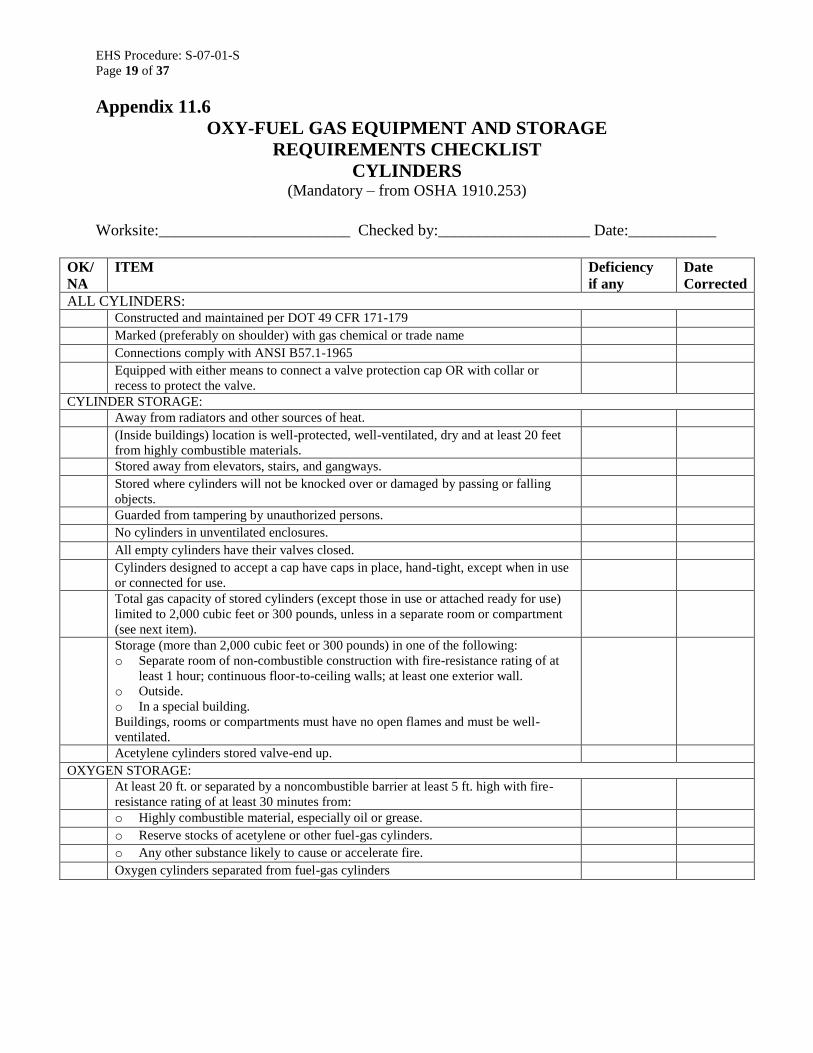
Appendix 11.6
OXY-FUEL GAS EQUIPMENT AND STORAGE
REQUIREMENTS CHECKLIST
CYLINDERS (Mandatory – from OSHA 1910.253)
Worksite:________________________ Checked by:___________________ Date:___________
OK/
NA
ITEM Deficiency
if any
Date
Corrected
ALL CYLINDERS:
Constructed and maintained per DOT 49 CFR 171-179
Marked (preferably on shoulder) with gas chemical or trade name
Connections comply with ANSI B57.1-1965
Equipped with either means to connect a valve protection cap OR with collar or
recess to protect the valve.
CYLINDER STORAGE:
Away from radiators and other sources of heat.
(Inside buildings) location is well-protected, well-ventilated, dry and at least 20 feet
from highly combustible materials.
Stored away from elevators, stairs, and gangways.
Stored where cylinders will not be knocked over or damaged by passing or falling
objects.
Guarded from tampering by unauthorized persons.
No cylinders in unventilated enclosures.
All empty cylinders have their valves closed.
Cylinders designed to accept a cap have caps in place, hand-tight, except when in use
or connected for use.
Total gas capacity of stored cylinders (except those in use or attached ready for use)
limited to 2,000 cubic feet or 300 pounds, unless in a separate room or compartment
(see next item).
Storage (more than 2,000 cubic feet or 300 pounds) in one of the following:
o Separate room of non-combustible construction with fire-resistance rating of at
least 1 hour; continuous floor-to-ceiling walls; at least one exterior wall.
o Outside.
o In a special building.
Buildings, rooms or compartments must have no open flames and must be well-
ventilated.
Acetylene cylinders stored valve-end up. OXYGEN STORAGE:
At least 20 ft. or separated by a noncombustible barrier at least 5 ft. high with fire-
resistance rating of at least 30 minutes from:
o Highly combustible material, especially oil or grease.
o Reserve stocks of acetylene or other fuel-gas cylinders.
o Any other substance likely to cause or accelerate fire.
Oxygen cylinders separated from fuel-gas cylinders

EHS Procedure: S-07-01-S
Page 20 of 37
Appendix 11.7
OXY-FUEL GAS EQUIPMENT REQUIREMENTS CHECKLIST
LOW-PRESSURE MANIFOLDS (Mandatory – from OSHA 1910.253)
Worksite:________________________ Checked by:___________________ Date:___________
OK/
NA
ITEM Deficiency
if any
Date
Corrected FUEL-GAS MANIFOLDS:
Fuel-gas cylinders connected to one manifold inside a building have total capacity no
more than 300 pounds of LPG or 3,000 cubic feet of other fuel-gas.
If capacity exceeds the above, fuel-gas cylinders are outside or in a separate room of
non-combustible construction with fire-resistance rating of at least 1 hour; continuous
floor-to-ceiling walls; at least one exterior wall OR are outdoors or in a separate
building.
Multiple manifolds in one building separated by either 50 ft. or a 5-ft noncombustible
barrier with a fire-resistance rating of at least 30 minutes.
Manifolds installed under supervision of someone familiar with the proper practices
for their construction and use.
Fuel-gas manifolds used only for the gas for which they were approved.
Indoors: Approved flash arrestors installed between coupled acetylene cylinders.
Outdoors: Approved flash arrestors installed between coupled acetylene cylinders,
OR (if no more than 3 cylinders are coupled) one flash arrestor may be installed
between the coupler block and the regulator.
Acetylene and liquefied fuel-gas cylinders are manifolded in a vertical position.
Pressure in gas cylinders connected to and discharged simultaneously through a
common manifold is approximately equal.
LOW-PRESSURE OXYGEN MANIFOLDS:
Used with cylinders with DOT service pressure no more than 200 psig.
Of substantial construction rated for use with oxygen at pressure of 250 psig.
Minimum bursting pressure of 1,000 psig.
Cylinders equipped with safety devices which relieve at max pressure of 250 psig, or
235 psig if vacuum insulation is used.
Hose and hose connections subject to cylinder pressure comply with hose
requirements below.
Hose has minimum bursting pressure of 1,000 psig.
Assembled manifold including leads has been tested and proven gas-tight at pressure
of 300 psig, using fluid which is oil-free and not combustible.
Manifold separated from fuel-gas cylinders or combustible materials (especially oil or
grease) by at least 20 feet or a noncombustible barrier at least 5 feet high with a fire-
resistance rating of at least 30 minutes.
Multiple manifolds in the same room are separated by at least 50 feet or a
noncombustible barrier at least 5 feet high with a fire-resistance rating of at least 30
minutes.
Manifolds installed under supervision of someone familiar with the proper practices
for their construction and use.
Oxygen manifolds used only for oxygen.
Sign posted at each manifold reading:
Low-Pressure Manifold
Do Not Connect High-Pressure Cylinders
Maximum Pressure – 250 psig(1.7 MPa)
EHS Procedure: S-07-01-S
Page 21 of 37
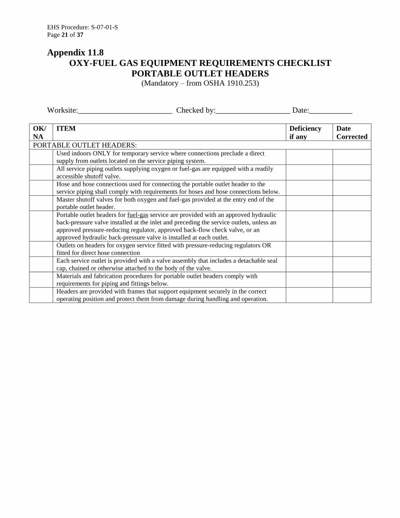
Appendix 11.8
OXY-FUEL GAS EQUIPMENT REQUIREMENTS CHECKLIST
PORTABLE OUTLET HEADERS (Mandatory – from OSHA 1910.253)
Worksite:________________________ Checked by:___________________ Date:___________
OK/
NA
ITEM Deficiency
if any
Date
Corrected
PORTABLE OUTLET HEADERS:
Used indoors ONLY for temporary service where connections preclude a direct
supply from outlets located on the service piping system.
All service piping outlets supplying oxygen or fuel-gas are equipped with a readily
accessible shutoff valve.
Hose and hose connections used for connecting the portable outlet header to the
service piping shall comply with requirements for hoses and hose connections below.
Master shutoff valves for both oxygen and fuel-gas provided at the entry end of the
portable outlet header.
Portable outlet headers for fuel-gas service are provided with an approved hydraulic
back-pressure valve installed at the inlet and preceding the service outlets, unless an
approved pressure-reducing regulator, approved back-flow check valve, or an
approved hydraulic back-pressure valve is installed at each outlet.
Outlets on headers for oxygen service fitted with pressure-reducing regulators OR
fitted for direct hose connection
Each service outlet is provided with a valve assembly that includes a detachable seal
cap, chained or otherwise attached to the body of the valve.
Materials and fabrication procedures for portable outlet headers comply with
requirements for piping and fittings below.
Headers are provided with frames that support equipment securely in the correct
operating position and protect them from damage during handling and operation.

EHS Procedure: S-07-01-S
Page 22 of 37
Appendix 11.9
OXY-FUEL GAS EQUIPMENT REQUIREMENTS CHECKLIST
SERVICE PIPING SYSTEMS, PAINTING AND SIGNS (Mandatory – from OSHA 1910.253)
Worksite:________________________ Checked by:___________________ Date:___________
OK/
NA
ITEM Deficiency
if any
Date
Corrected
SERVICE PIPING SYSTEMS:
Piping and fittings comply with section 2, Industrial Gas and Air Piping Systems, of
the ANSI Code for Pressure Piping ANSI B31.1-1967, unless it conflicts with any of
the requirements below.
Pipe is at least Schedule 40.
Fittings are at least standard weight in sizes up to and including 6-inch nominal.
Copper tubing is Types K or L in accordance with the Standard Specification for
Seamless Copper Water Tube, ASTM B88-6a.
Piping is steel, wrought iron, brass or copper pipe, or seamless copper, brass or
stainless steel tubing, except as provided below.
Oxygen piping and fittings at pressures more than 700 psi are stainless steel or copper
alloys.
Hose connections and hose complying with requirements in that section of this
checklist may be used to connect outlets of manifold pressure regulators to piping if
the working pressure of the piping is 250 psi or less and hose is 5 feet long or less,
and hose has a minimum bursting pressure of 1,000 psig.
Where oxygen is supplied to service piping systems from low-pressure oxygen
manifolds without intervening pressure regulating devices, piping system has a
minimum design pressure of 250 psig AND a pressure regulator is provided at each
station outlet.
Piping for acetylene or acetylenic compounds is steel or wrought iron.
No unalloyed copper is used for acetylene or acetylenic compounds except as listed
above.
Piping joints in steel or wrought iron piping are welded, threaded or flanged.
Fittings such as ells, tees, couplings and unions are rolled, forged or cast steel,
malleable iron or nodular iron.
No gray or white cast iron fittings.
Joints in brass or copper pipe are welded, brazed, threaded or flanged. If of the socket
type, they are brazed with silver-brazing alloy or similar high melting point (not less
than 8000F) filler metal.
Joints in seamless copper, brass, or stainless steel tubing are approved gas tubing
fittings or are brazed. If of the socket type, they are brazed with silver-brazing alloy
or similar high melting point (not less than 800F) filler metal.
Distribution lines installed and maintained in safe operating condition.
Piping is run as directly as practicable, protected against physical damage, proper
allowance made for expansion and contraction, jarring and vibration.
Pipe laid underground in earth is located below the frost line and protected against
corrosion.
After assembly, pipe is thoroughly blown out with air, nitrogen or CO2 to remove
foreign materials. For oxygen piping, only oil-free gases are used.
Only piping which has been welded or brazed is installed in tunnels, trenches or
ducts.

EHS Procedure: S-07-01-S
Page 23 of 37
OK/
NA
ITEM Deficiency
if any
Date
Corrected
Shutoff valves are located outside of conduits (tunnels, trenches or ducts).
Good natural or forced ventilation is provided where oxygen piping and fuel-gas
piping are placed in the same tunnel, duct or trench
Low points in piping carrying moist gas:
o Are drained and pumped as needed, and equipped with drain valves.
o Drain valves have outlets normally closed with screw caps or plugs.
o No open end valves or petcocks are used except for drips located outdoors,
underground AND not readily accessible – if equipped with means to secure
them in a closed position.
o Pipes leading to ground surface are cased or jacketed as needed to prevent
loosening or breaking.
Gas cocks or valves are provided for all buildings at points where they will be readily
accessible for emergency gas supply shutoff.
Shutoff valve is provided in discharge lines from generators, gas holds, manifolds and
other sources of supply.
Shutoff valves will not interfere with operation of safety relief devices.
During installation of new piping:
o Fittings and pipe lengths are examined internally before assembly and freed from
scale or dirt if needed.
o Oxygen piping is washed out with a solution (such as hot water solutions of
caustic soda or trisodium phosphate) which will remove grease or dirt but not
react with oxygen.
o Piping is thoroughly blown out after assembly in order to remove foreign
materials. Only oil-free gases are used in oxygen lines. For other piping air or
inert gas may be used.
Sources of ignition are isolated from uncapped openings in gas lines or other
equipment which has contained flammable gases.
PAINTING AND SIGNS:
Underground pipe and tubing and outdoor ferrous pipe and tubing is covered or
painted with material which protects against corrosion.
Aboveground piping systems are marked in accordance with the ANSI Scheme for
the Identification of Piping Systems, ANSI A13.1-1956.
Station outlets are marked with the name of the gas they contain.

EHS Procedure: S-07-01-S
Page 24 of 37
Appendix 11.10
OXY-FUEL GAS EQUIPMENT REQUIREMENTS CHECKLIST
PROTECTIVE EQUIPMENT, HOSE AND REGULATORS (Mandatory – from OSHA 1910.253)
Worksite:________________________ Checked by:___________________ Date:___________
OK/
NA
ITEM Deficiency
if any
Date
Corrected
PROTECTIVE EQUIPMENT, HOSE AND REGULATORS:
Used only in the service for which it was installed.
Installed and used only as recommended by the manufacturer.
Service piping is protected by pressure relief devices:
o Set to function at not more than the system design pressure.
o Discharging upwards to a safe location.
Fuel-gas and oxygen piping systems, including portable outlet headers, incorporate
protective equipment shown in the figures below. Only the portions of the fuel-gas
system that are to be used with oxygen need to comply.
Approved protective equipment (designated P(F) in the figures above) is installed in
fuel-gas piping to prevent:
o Backflow of oxygen into the fuel-gas supply system, or fuel into the oxygen
system.
o Passage of a flash back into the fuel-gas supply system.
o Excessive back pressure of oxygen into the fuel-gas supply system.
The three functions can be combined in one device or provided by separate devices.
Devices are located as shown in the figure above. Only approved devices are used.

EHS Procedure: S-07-01-S
Page 25 of 37
OK/
NA
ITEM Deficiency
if any
Date
Corrected
Back-pressure protection as required above:
o Is set at no more than the pressure rating of the backflow or flashback protection
device, whichever is lower.
o Is located downstream of the backflow and flashback protection devices.
o Has a vent at least as large and the relief device inlet.
o Is installed without low points that might collect moisture, unless low points are
unavoidable, in which case drip pots with drains closed with screw plugs or caps
are installed at the low points.
Backpressure venting:
o Does not endanger personnel or property through gas discharge.
o Is located away from ignition sources.
o Ends in a hood or bend.
If pipeline protective equipment incorporates a liquid:
o Liquid levels are maintained.
o A suitable antifreeze is used if needed to prevent freezing.
Fuel gas for use with equipment not requiring oxygen is withdrawn upstream of
piping protective devices.
STATION OUTLET PROTECTIVE EQUIPMENT:
A check valve, pressure regulator, hydraulic seal, or combination is provided at each
station outlet, including portable headers, to prevent backflow, as shown in the figure
above, unless approved pipeline protective equipment is located at the station outlet.
A shutoff valve (V(F) and V(O)) is:
o Installed at each station outlet.
o Located on the upstream side of other station outlet equipment.
Station outlets equipped with a detachable regulator terminate in a union connection
that complies with Regulator Connection Standards, 1958, Compressed Gas
Association and Rubber Manufacturers Association.
Station outlets connected directly to a hose terminate in a union connection
complying with the Standard Hose Specifications, 1957, Compressed Gas Association
and Rubber Manufacturers Association.
Station outlets may terminate in pipe threads to which permanent connections are to
be made, such as to a machine.
All station outlets are equipped with a detachable outlet seal cap secured in place
which is used to seal the outlet except when a hose, regulator, or piping is attached.
No more than four torches supplied from any one station outlet, and then only if each
outlet is equipped with a shutoff valve and fuel-gas capacity from any one torch is no
more than 15 cubic feet per hour. (Does not apply to machines.)

EHS Procedure: S-07-01-S
Page 26 of 37
Appendix 11.11
OXY-FUEL GAS EQUIPMENT REQUIREMENTS CHECKLIST
HOSE AND HOSE CONNECTIONS, PRESSURE-REDUCING
REGULATORS (Mandatory – from OSHA 1910.253)
Worksite:________________________ Checked by:___________________ Date:___________
OK/
NA
ITEM Deficiency
if any
Date
Corrected
HOSE AND HOSE CONNECTIONS:
Hose for oxy-fuel gas service complies with the Specification for Rubber Welding
Hose, 1958, Compressed Gas Association and Rubber Manufacturers Association.
When parallel lengths of oxygen and acetylene hose are taped together for
convenience and to prevent tangling, not more than 4” out of 12” is covered by tape.
Hose connections comply with the Standard Hose Connection Specifications, 1957,
Compressed Gas Association.
Hose connections are clamped or otherwise securely fastened so as to withstand,
without leakage, 2x service pressure, but no less than 300 psi.
Oil-free air or oil-free inert gas is used for all pressure testing of hose.
Hose showing leaks, burns, worn places, or other defects rendering it unfit for service
is repaired or replaced.
PRESSURE-REDUCING REGULATORS:
Used only for the gas and pressures for which they were intended.
Regulator inlet connections comply with the Regulator Connection Standards, 1958,
Compressed Gas Association.
Repair on regulators or regulator parts are done only by skilled mechanics who have
been properly instructed.
Gauges on oxygen regulators are marked “USE NO OIL.”
Seats on union nuts and regulator connections are intact and will not cause gas
leakage when regulators are attached to cylinder valves.

EHS Procedure: S-07-01-S
Page 27 of 37
Appendix 11.12
RESISTANCE WELDING EQUIPMENT CHECKLIST (Mandatory – from OSHA 1910.255)
Worksite:________________________ Checked by:___________________ Date:___________
OK/
NA
ITEM Deficiency
if any
Date
Corrected
GENERAL REQUIREMENTS:
All equipment is installed by a Qualified Electrician in conformance with OSHA
1910 Subpart S.
Each power circuit is equipped with a safety-type disconnect or circuit
breaker/interrupter, conveniently located at or near the machine.
Ignition tubes are equipped with a thermal protection switch.
Controls of all automatic or air and hydraulic clamps are arranged or guarded to
prevent the operator from accidentally activating them.
SPOT AND SEAM WELDING MACHINES:
All external weld initiating control circuits operate on voltage not more than 120
volts.
High-voltage (over 550 V) stored-energy / capacitor discharge welding equipment:
o Insulated and completely enclosed.
o Doors are provided with interlocks and contacts wired into the control circuit.
o Equipped with a manual switch or other device for manual shutoff if automatic
interlocks fail.
All doors and access panels are kept locked and interlocked to prevent access by
unauthorized persons.
Press welding machines where there is a possibility of the operator’s fingers being
under the point of operation are guarded by electric eye, two hand controls or other
employee protection.
Shield guards of safety glass or suitable fire-resistant plastic are installed where
practicable to eliminate flying spark hazards for equipment users as well as passing
personnel.
Foot switches are guarded to prevent accidental operation of the machine.
Two or more emergency stop buttons are provided on all special multipost welding
machines, including 2-post and 4-post weld presses.
Large machines: Four safety pins and receptacles are provided to render the press
inoperative when pins are removed and inserted into the ram or platen.
Grounding:
o Where technically practical, the secondary welding transformer used in
multipost, projection and seam welding machines is grounded by permanently
grounding of the welding secondary current circuit.
o Where the above is not practical, a center tapped grounding reactor connected
across the secondary or a safety disconnect switch in conjunction with the
welding control is used. Safety disconnects are arranged to open both sides of
the line when the welding current is not present.
PORTABLE WELDING MACHINES:
Portable welding guns have counterbalanced devices to support guns and cables
unless the design of the gun or fixture makes counterbalancing impractical or
unnecessary.

EHS Procedure: S-07-01-S
Page 28 of 37
OK/
NA
ITEM Deficiency
if any
Date
Corrected
All portable welding guns, transformers and related equipment which is suspended
from overhead is equipped with safety chains or cables capable of supporting the total
shock load in the event of failure of any part of the support system.
Each clevis is capable of supporting the total shock load of the suspended equipment
in case of trolley failure.
All initiating switches, including retraction and dual schedule switches, located on the
welding gun are equipped with guards to prevent accidental initiation through contact
with items such as fixtures or operator clothing.
Initiating switches do not exceed 24 volts.
Movable holders have enough clearance to prevent shearing of fingers.
Secondary and case of all portable welding transformers is grounded with a center
tapped secondary or a center tapped grounding reactor connected across the
secondary.
FLASH WELDING EQUIPMENT:
Equipped with a hood to control flying flash.
Ventilation provided in cases of high production where materials may contain a film
of oil and where toxic elements and metal fumes are given off.

EHS Procedure: S-07-01-S
Page 29 of 37
Appendix 11.13
ARC WELDING EQUIPMENT OPERATION AND MAINTENANCE (Mandatory per OSHA 1910.254)
Workers assigned to operate and maintain arc welding equipment must be acquainted with
equipment requirements and with general Hot Work requirements.
1. Before starting operations, check all machine connections to be sure they are properly
made.
1.1. Work lead must be firmly attached to the work.
1.2. Magnetic work clamps must be freed of adherent metal particles of spatter on contact
surfaces.
1.3. Coiled welding cable must be spread out before use to avoid serious overheating and
damage to insulation.
2. Check welding machine frame grounding, especially for portable machines.
3. Check for leaks of cooling water, shielding gas or engine fuel. No welding permitted if
such are found.
4. Determine that proper switching equipment for shutting down the machine is provided.
5. Follow manufacturer’s printed rules and instructions for equipment operation.
6. When not in use, place electrode holders so that they cannot make electrical contact with
persons, conducting objects, fuel or compressed gas tanks.
7. Do not use cords with splices within 10 feet of the electrode holder.
8. Do not coil or loop welding electrode cable around parts of the body while welding.
9. Report any equipment defect or safety hazard to supervisor and discontinue use of
equipment until its safety has been assured.
10. Equipment repairs shall be made only by qualified personnel.
11. Machines which have become wet must be thoroughly dried and tested before being used.
12. Cables with damaged insulation or exposed bare conductors shall be replaced.
13. Join lengths of work and electrode cables by use of connecting means specifically intended
for the purpose, with insulation adequate for service conditions.

EHS Procedure: S-07-01-S
Page 30 of 37
Appendix 11.14
ARC WELDING EQUIPMENT CHECKLIST (Mandatory – from OSHA 1910.254)
Worksite:________________________ Checked by:___________________ Date:___________
OK/
NA
ITEM Deficiency
if any
Date
Corrected
DESIGN:
Equipment meets design requirements of NEMA EW-1-1962 – Requirements
for Electric Arc-Welding Apparatus, National Electrical Manufacturers
Association, OR Safety Standard for Transformer-Type Arc-Welding
Machines, ANSI C33.2-1956, Underwriters’ Laboratories.
Arc welding machines are designed and constructed to carry their rated load
with rated temperature rises where cooling-air temperature does not exceed
104F and where altitude does not exceed 3,300 feet.
Arc welding equipment is suitable for operation in atmospheres containing
dust, gases, and light rays produced by the welding arc.
Arc welding equipment meets special requirements for unusual service
conditions in which it is operated, such as exposure to:
o Unusually corrosive fumes.
o Steam or excessive humidity.
o Excessive oil vapor.
o Flammable gases.
o Abnormal vibration or shock.
o Excessive dust.
o Weather.
o Unusual seacoast or shipboard conditions.
Voltage limits as below are not exceeded:*
o AC Manual arc welding and cutting – 80 V.
o AC Automatic (machine or mechanized) arc welding and cutting – 100 V.
o DC Manual arc welding and cutting – 100 V.
o DC Automatic arc welding and cutting – 100 V.
* When special processes require values higher than the above, operator is
protected from making accidental contact with the voltage by adequate
insulation or other means.
AC welders used under wet conditions or warm surroundings where
perspiration is a factor are equipped with reliable automatic controls for
reducing no-load voltage.
Controllers on electric motor-driven welders:
o Are integrally mounted.
o Have capacity for carrying rated motor current.
o Are capable or making and interrupting stalled rotor current of the motor.
o May serve as the running over current device if provided with the number
or over current units as specified by OSHA Subpart S.
All arc welding controls are enclosed except for operating wheels, levers, or
handles.
Input power terminals, tap change devices and live metal parts connected to
input circuits are completely enclosed and accessible only by means of tools.
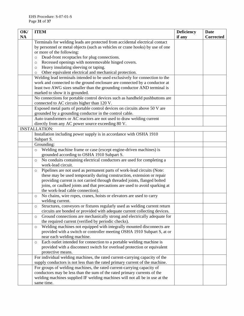
EHS Procedure: S-07-01-S
Page 31 of 37
OK/
NA
ITEM Deficiency
if any
Date
Corrected
Terminals for welding leads are protected from accidental electrical contact
by personnel or metal objects (such as vehicles or crane hooks) by use of one
or more of the following:
o Dead-front receptacles for plug connections.
o Recessed openings with nonremovable hinged covers.
o Heavy insulating sleeving or taping.
o Other equivalent electrical and mechanical protection.
Welding lead terminals intended to be used exclusively for connection to the
work and connected to the ground enclosure are connected by a conductor at
least two AWG sizes smaller than the grounding conductor AND terminal is
marked to show it is grounded.
No connections for portable control devices such as handheld pushbuttons are
connected to AC circuits higher than 120 V.
Exposed metal parts of portable control devices on circuits above 50 V are
grounded by a grounding conductor in the control cable.
Auto transformers or AC reactors are not used to draw welding current
directly from any AC power source exceeding 80 V.
INSTALLATION:
Installation including power supply is in accordance with OSHA 1910
Subpart S.
Grounding:
o Welding machine frame or case (except engine-driven machines) is
grounded according to OSHA 1910 Subpart S.
o No conduits containing electrical conductors are used for completing a
work-lead circuit.
o Pipelines are not used as permanent parts of work-lead circuits (Note:
these may be used temporarily during construction, extension or repair
providing current is not carried through threaded joints, flanged bolted
joins, or caulked joints and that precautions are used to avoid sparking at
the work-lead cable connection).
o No chains, wire ropes, cranes, hoists or elevators are used to carry
welding current.
o Structures, conveyors or fixtures regularly used as welding current return
circuits are bonded or provided with adequate current collecting devices.
o Ground connections are mechanically strong and electrically adequate for
the required current (verified by periodic checks).
o Welding machines not equipped with integrally mounted disconnects are
provided with a switch or controller meeting OSHA 1910 Subpart S, at or
near each welding machine.
o Each outlet intended for connection to a portable welding machine is
provided with a disconnect switch for overload protection or equivalent
protective means.
For individual welding machines, the rated current-carrying capacity of the
supply conductors is not less than the rated primary current of the machine.
For groups of welding machines, the rated current-carrying capacity of
conductors may be less than the sum of the rated primary currents of the
welding machines supplied IF welding machines will not all be in use at the
same time.

EHS Procedure: S-07-01-S
Page 32 of 37
OK/
NA
ITEM Deficiency
if any
Date
Corrected
In operations involving several welders on one structure, DC welding process
equipment may require use of both polarities, or supply circuit limitations of
AC welding may require distribution of machines among the phases of the
supply circuit. In such cases no load voltages between electrode holders will
be:
o 2 x normal in DC machines.
o 1, 1.41, 1.73 or 2 x normal in AC machines.
Similar voltage differences will exist if both AC and DC welding are done on
the same structure.
All DC machines are connected with the same polarity.
All AC machines are connected to the same phase of the supply circuit and
with the same instantaneous polarity.

EHS Procedure: S-07-01-S
Page 33 of 37
Appendix 11.15
HEALTH HAZARDS AND FUME PROTECTION REQUIREMENTS ASSOCIATED WITH WELDING, CUTTING, SOLDERING AND BRAZING*
*Reference Respiratory Protection Procedure and PPE Procedure and all applicable craft specific procedures for more details.
HAZARD OEL HEALTH HAZARD SYMPTOM ASSOCIATED WITH OVER EXPOSURE
OUTSIDE SHOP/ENCLOSED BUILDING CONFINED
SPACES
Aluminum (Al) 5 mg/m3 Absorbed in the lungs and may result in a
disease of the lungs call pneumoconiosis or "dusty lungs".
Irritation of skin, eyes, nose, and throat. Natural ventilation in large open area. Mechanical Ventilation Conditions may warrant respirators.
Mechanical Ventilation and/or Airline respirators
Beryllium (Be) 0.002 mg/m
3
May result in lung damage. Similar to asbestos, damage may not show up for several years after excessive exposure,
(Be) is suspected carcinogen.
Respiratory tract irritation, weakness, fatigue, and weight loss.
Exhaust hoods and Airline respirators. Air Purifying Respirators With Local Exhaust or
Airline Respirators with No Mechanical Ventilation
Mechanical Ventilation. Airline
Respirators shall be required.
Cadmium (Cd) 0.002 mg/m
3
May cause bronchitis, pneumonitis, and pulmonary edema. Liver, kidney, or bone marrow may also be injured. (Cd) is a
suspected carcinogen.
Respiratory tract irritation accompanied by sore throat, and a metallic taste in
the mouth. Coughing, chest pain, nausea, headache, diarrhea, and labored breathing may follow over
exposure.
Natural ventilation and respirators in large open areas.
Air Purifying Respirators With Local Exhaust or
Airline Respirators with No Mechanical Ventilation
Mechanical Ventilation. Airline
Respirators shall be required.
Chromium VI (Cr)
0.005 mg/m
3
Is suspected to cause lung cancer and has been associated with blood, liver, and
kidney disorders.
May cause coughing, edema and bronchitis. Some oxides of chromium can produce small painless skin ulcers
and dermatitis.
Natural ventilation and respirators in large open areas.
Air Purifying Respirators With Local Exhaust or
Airline Respirators with No Mechanical Ventilation
Mechanical Ventilation. Airline
Respirators shall be required.
Carbon Monoxide
(CO)
25 ppm Combines with the hemoglobin in the blood, interfering with the up-take of (O2)
causing a form of anoxia.
Headaches, possible dizziness, and a general discomfort.
Natural ventilation in large open area. Mechanical Ventilation or Airline Respirators
Mechanical Ventilation and/or Airline respirators
Copper (Cu) 0.1 mg/m3 Irritation of the upper respiratory tract.
May also cause metal fume fever. Metallic or sweet taste in the mouth,
nausea, and in some instances, it may cause discoloration of the hair and skin.
Natural ventilation and respirators in large open areas.
Air Purifying Respirators With Local Exhaust or
Airline Respirators with No Mechanical Ventilation
Mechanical Ventilation and/or Airline respirators
Fluorides 2.5 mg/m3 Inhalation of high concentration of fluoride
dust or fumes may produce respiratory tract irritation. Fluorides may also be
absorbed into the bones.
Chills, fever, shortness of breath (dyspnea), coughing, eye irritation,
nausea, thirst, and sweating.
Natural ventilation in large open areas. Respirator may be required.
Exhaust hoods or Airline Respirators Exhaust hoods and/or
Airline Respirators
Iron Oxide (Fe203)
5 mg/m3 May cause a benign pneumoconiosis
referred as siderosis. It is not disabling but could be mistakenly diagnosed as
tuberculosis or silicosis when X-rays are examined.
Some scientists believe a symptom of over exposure may be stomach
cramps.
Natural ventilation in large open areas. Mechanical Ventilation. Air Purifying Respirators may be required.
Mechanical Ventilation. Airline Respirators may be
required.
Lead (Pb) .05 mg/m3 An accumulation of lead may cause
serious damage to the liver, spleen, kidneys, heart, lungs, brain, muscles, skeletal and reproductive systems.
Lead poisoning includes abdominal pain, headaches, weakness, muscular
aches or cramps, loss of appetite, nausea and vomiting.
Natural ventilation and respirators in large open areas.
Exhaust hoods or Airline Respirators Exhaust hoods and Airline Respirators

EHS Procedure: S-07-01-S
Page 34 of 37
HAZARD OEL HEALTH HAZARD SYMPTOM ASSOCIATED WITH OVER EXPOSURE
OUTSIDE SHOP/ENCLOSED BUILDING CONFINED
SPACES
Manganese (Mn)
0.2 mg/m3 Irritating to the upper respiratory tract and
eyes. May also cause chronic effects to the nervous system.
Freshly formed fumes may cause symptoms similar to those experienced with metal fume fever, chills and fever. Mental confusion, dry throat, coughing, tightness in the chest and shortness of
breath may also occur.
Natural ventilation in large open areas. Air Purifying Respirators With Local Exhaust or
Airline Respirators with No Mechanical Ventilation
Mechanical Ventilation. Airline Respirators may be
required.
Magnesium (Mg)
10 mg/m3 May induce metal fume fever. Slows the
body natural healing process. Eye and nose irritation. Wounds,
scratches, or cuts contaminated with (Mg) healing process is slowed down.
Natural ventilation in large open areas. Air Purifying Respirators With Local Exhaust or
Airline Respirators with No Mechanical Ventilation
Mechanical Ventilation. Airline Respirators may be
required.
Mercury (Hg) 0.025 mg/m
3
May cause bronchitis, pneumonitis, gastrointestinal disorders, and anorexia.
Cough, chest pain, shortness of breath, tremors, insomnia, and eye and skin
irritation.
Natural ventilation and respirators in large open areas.
Exhaust hoods or Airline Respirators Exhaust hoods and Airline Respirators
Nickel (Ni) .1 mg/m3 Studies have shown that (Ni) dust and
fumes introduced into the pleural cavity, muscle and subcutaneous tissue of laboratory animals have resulted in
cancer.
(Ni) eczema or "nickel itch" is common in welders using nickel compounds. Headaches, dizziness, nausea, and
weakness.
Natural ventilation and respirators in large open areas.
Air Purifying Respirators With Local Exhaust or
Airline Respirators with No Mechanical Ventilation
Mechanical Ventilation. Airline
Respirators shall be required.
Ozone (03) 0.1 ppm Respiratory diseases may occur years after excessive exposure. Irritating to the
respiratory tract, eyes, mucous membranes and mainly irritating to the
lungs.
Less severe exposu4re may produce headaches, malaise, shortness of
breath, and drowsiness.
Natural ventilation in large open areas. Local Exhaust Ventilation or Airline Respirators
Mechanical Ventilation and/or Airline respirators
Phosgene (COCI2)
{Decomposition of
Trichloroethylene}
0.1 ppm May cause eye and upper respiratory tract irritation, fluid build - up in the lungs,
oxygen deficiency to the blood and dermatitis.
Dry burning throat, vomiting, coughing, foamy saliva, shortness of breathe, chest pain, bluish or purplish skin discoloration, and burn to the skin.
Natural ventilation and respirators in large open areas.
Exhaust hoods and Airline Respirators Exhaust hoods and Airline Respirators
Phosphorus (P4)
.02ppm May cause eye and respiratory tract irritation, jaundice, anemia, dental and jaw
pain.
Nausea, abdominal pain, excessive saliva, and burns to skin and eyes.
Natural ventilation and respirators in large open areas.
Exhaust hoods and Airline Respirators
Exhaust hoods and Airline Respirators
Tin (Sn) 2 mg/m3 Inorganic (Sn) may result in "stannosis", a
benign dust disease. Stannosis is a form of pneumoconiosis. There has been no
evidence of disability or special complicating factors.
Eye and skin irritation. Natural ventilation in large open areas. Local Exhaust Ventilation or Airline Respirators
Mechanical Ventilation and/or Airline respirators
Titanium Dioxide (TiO2)
10 mg/m3 Slight lung fibrosis may form. (Ti) is a
suspected carcinogen. Irritation of mucous membranes, eyes,
nose and throat. Natural ventilation in large open areas. Local Exhaust. Respirators
may be required. Mechanical
Ventilation and/or Airline respirators
Vanadium (V) 0.05 mg/m3 Can cause "green tongue", paleness,
physical deterioration of the body. Irritation to the respiratory tract
Soar throat, coughing, bronchitis and chest pains. Shortness of breath and
eye irritation may occur.
Natural ventilation in large open areas. Local Exhaust. Respirators may be required.
Mechanical Ventilation and/or Airline respirators

EHS Procedure: S-07-01-S
Page 35 of 37
Appendix 11.16
PERSONAL PROTECTIVE EQUIPMENT REQUIRMENTS FOR WELDING, CUTTING, SOLDERING AND BRAZING*
*Reference Respiratory Protection Procedure and PPE Procedure and all applicable craft specific procedures for more details.
HAZARD/TASK RESPIRATOR CLOTHING GLOVES EYES/FACE FOOTWEAR HAT OTHER
CUTTING – UV RADIATION
See Cutting –
Fumes & Gases
Goggles or
Welding Hood MINIMUM
OXYGEN-ACETYLENE:
Light(Plate < 1” thick)
Medium(Plate 1”-6” thick)
Heavy(Plate > 6” thick)
FRC Leather
Leather
Leather or Welding Welding
Welding
SHADE NUMBER
3 4
5
Leather Leather
Leather
Hard Hard
Hard
AIR CARBON/ARC(Gouging):
Light ( < 500 Arc Current)
Heavy (500-1000 Arc Current)
Leather
Leather
Welding
Welding
10
11
Leather
Leather
Hard
Hard
Flash Curtains or
Equivalent Shielding
Hearing Protection
Device(s) PLASMA ARC:
Light < 300 Arc Current
Medium (300-400 Arc Current)
Heavy (400-800 Arc Current)
Leather
Leather
Leather
Welding
Welding
Welding
8
9
10
Leather
Leather
Leather
Hard
Hard
Hard
WELDING – UV RADIATION
OXYGEN-ACETYLENE WELDING:
Light(Plate <1/8” thick)
Medium (Plate 1/8” – ½” thick)
Heavy (Plate > ½” thick)
See Welding – Fumes & Gases
Leather
Leather
Leather
Welding
Welding
Welding
Welding Hood
MINIMUM
SHADE NUMBER 4
5
6
Leather
Leather
Leather
Hard
Hard
Hard
Flash Curtains or
Equivalent Shielding
SHIELDED METAL ARC WELDING
(Rod or Electrode):
Rod < 3/32” & < 60 Arc Current
Rod 3-5/32” & 60-160 Arc Current Rod 5-8/32” & 160-250 Arc Current
Rod > 8/32” & 250-550 Arc Current
Leather
Leather
Leather Leather
Welding
Welding
Welding Welding
7
8 10
11
Leather
Leather
Leather Leather
Hard
Hard
Hard Hard
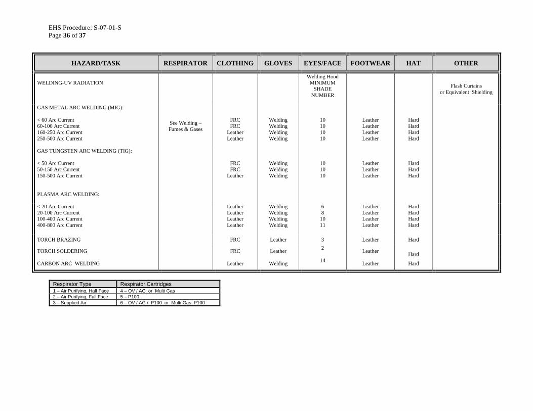
EHS Procedure: S-07-01-S
Page 36 of 37
HAZARD/TASK RESPIRATOR CLOTHING GLOVES EYES/FACE FOOTWEAR HAT OTHER
WELDING-UV RADIATION
Welding Hood
MINIMUM SHADE
NUMBER
Flash Curtains
or Equivalent Shielding
GAS METAL ARC WELDING (MIG):
< 60 Arc Current 60-100 Arc Current
160-250 Arc Current
250-500 Arc Current
See Welding –
Fumes & Gases
FRC FRC
Leather
Leather
Welding Welding
Welding
Welding
10 10
10
10
Leather Leather
Leather
Leather
Hard Hard
Hard
Hard
GAS TUNGSTEN ARC WELDING (TIG):
< 50 Arc Current
50-150 Arc Current
150-500 Arc Current
FRC
FRC
Leather
Welding
Welding
Welding
10
10
10
Leather
Leather
Leather
Hard
Hard
Hard
PLASMA ARC WELDING:
< 20 Arc Current
20-100 Arc Current 100-400 Arc Current
400-800 Arc Current
Leather
Leather Leather
Leather
Welding
Welding Welding
Welding
6
8 10
11
Leather
Leather Leather
Leather
Hard
Hard Hard
Hard
TORCH BRAZING FRC Leather 3 Leather Hard
TORCH SOLDERING FRC Leather 2
Leather
Hard
CARBON ARC WELDING Leather Welding 14
Leather Hard
Respirator Type Respirator Cartridges
1 – Air Purifying, Half Face 4 – OV / AG or Multi Gas
2 – Air Purifying, Full Face 5 – P100
3 – Supplied Air 6 – OV / AG / P100 or Multi Gas P100

EHS Procedure: S-07-01-S
Page 37 of 37
HAZARD / TASK RESPIRATOR RESPIRATOR RESPIRATOR
WELDING – FUMES & GASES
SHOP
FIELD
CONFINED SPACES
Good Ventilation
Poor Ventilation
Good Ventilation
Poor Ventilation
Good Ventilation
Poor Ventilation
OXYGEN-ACETYLENE
Carbon Steel
Other Alloys
None
None
(1) (5)
(1) (5)
None
None, except for
Galvanized (1)(5)
(1)(5)
(1)(5)
(1)(6)
(1)(6)
(3)
(3)
SHIELDED METAL ARC WELDING (Rod or
Electrode)
Carbon Steel Other Alloys
None None
(1)(5) (1)(5)
None None
(1)(5) (1)(6)
(1)(5) (3)
(3) (3)
GAS METAL ARC WELDING (MIG)
Carbon Steel
Other Alloys
None
None
(1)(5)
(1)(5)
None
None
(1)(5)
(1)(6)
(1)(5)
(3)
(3)
(3)
GAS TUNGSTEN ARC WELDING (TIG)
Carbon Steel Other Alloys
None
None
(1)(5)
(1)(5)
None
None
(1)(5)
(1)(6)
(1)(5)
(3)
(3)
(3)
Respirator Type Respirator Cartridges
1 – Air Purifying, Half Face 4 – OV / AG or Multi Gas
2 – Air Purifying, Full Face 5 – P100
3 – Supplied Air 6 – OV / AG / P100 or Multi Gas P100
NOTE: All Hot work (Cutting, Grinding, Welding) on alloy metals must comply with the Hexavalent
Chromium Standard (Under Development)