ehv power cable system - zircon · ehv power cable system power cables cable accessories
TRANSCRIPT
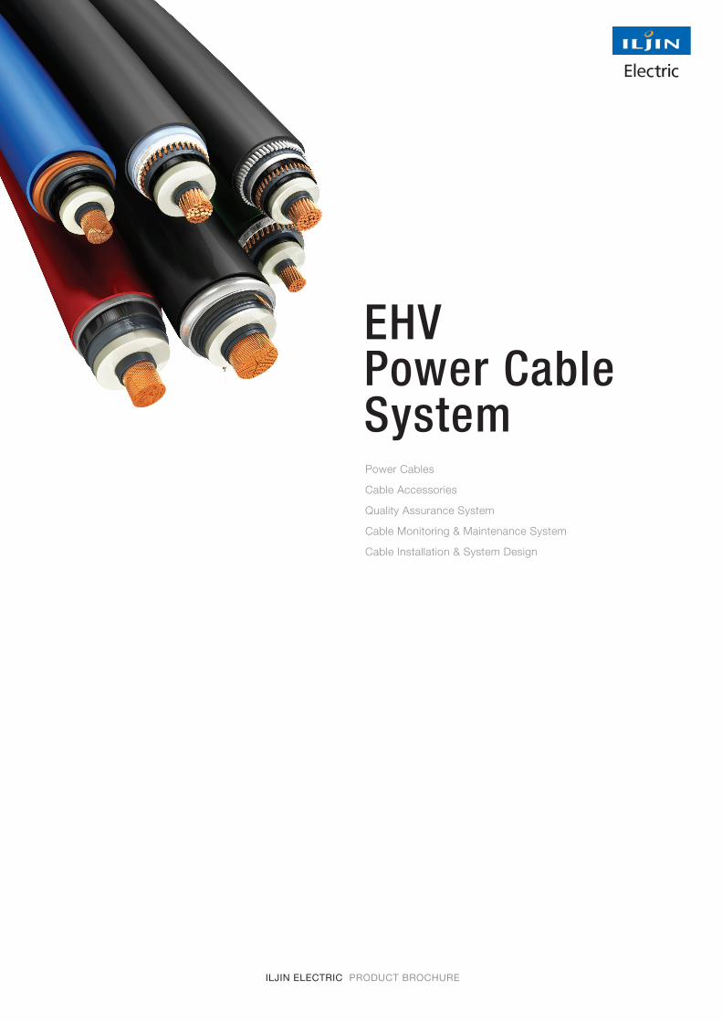
EHV Power Cable SystemPower Cables
Cable Accessories
Quality Assurance System
Cable Monitoring & Maintenance System
Cable Installation & System Design
ILJIN ELECTRIC PRODUCT BROCHURE
1_Introduction 04p
2_Power Cables 05p
3_Cable Accessories 23p
4_Quality Assurance System 30p
5_Cable Monitoring & Maintenance System 31p
6_Cable Installation & System Design 32p
2
Contents | Introduct ion | TECH data | Laying Condit ions | Accessor ies | System | Instal lat ion
Passion forconnecting
the worldthrough
Power cables
3
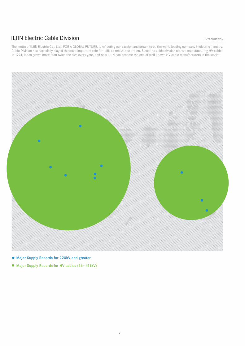
The motto of ILJIN Electric Co., Ltd., FOR A GLOBAL FUTURE, is reflecting our passion and dream to be the world leading company in electric industry. Cable Division has especially played the most important role for ILJIN to realize the dream. Since the cable division started manufacturing HV cables in 1994, it has grown more than twice the size every year, and now ILJIN has become the one of well-known HV cable manufacturers in the world.
ILJIN Electric Cable Division INTRODUCTION
Major Supply Records for 220kV and greater
Major Supply Records for HV cables (66~161kV)
4
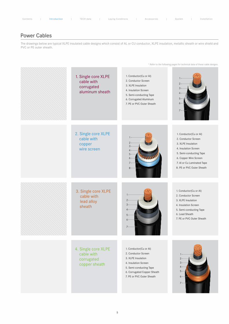
Power CablesThe drawings below are typical XLPE insulated cable designs which consist of AL or CU conductor, XLPE insulation, metallic sheath or wire shield and PVC or PE outer sheath.
* Refer to the following pages for technical data of these cable designs.
4. Single core XLPE cable with corrugated copper sheath
1. Single core XLPE cable with corrugated aluminum sheath
2. Conductor Screen
3. XLPE Insulation
4. Insulation Screen
1. Conductor(Cu or Al)
5. Semi-conducting Tape
6. Corrugated Aluminum
7. PE or PVC Outer Sheath
2. Conductor Screen
3. XLPE Insulation
4. Insulation Screen
1. Conductor(Cu or Al)
5. Semi-conducting Tape
6. Corrugated Copper Sheath
7. PE or PVC Outer Sheath
1
2
3
4
5
6
7
1
2
3
4
5
6
7
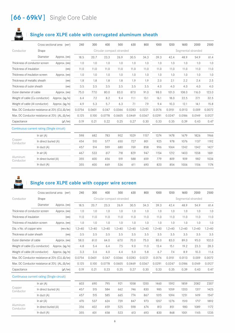
2. Single core XLPE cable with copper wire screen
2. Conductor Screen
3. XLPE Insulation
6. Copper Wire Screen
4. Insulation Screen
7. Al or Cu Laminated Tape
1. Conductor(Cu or Al)
5. Semi-conducting Tape
8. PE or PVC Outer Sheath
1
23
456
7
8
3. Single core XLPE cable with lead alloy sheath
2. Conductor Screen
3. XLPE Insulation
4. Insulation Screen
1. Conductor(Cu or Al)
5. Semi-conducting Tape
6. Lead Sheath
7. PE or PVC Outer Sheath
1
2
3
4
5
6
7
Contents | Introduct ion | TECH data | Laying Condit ions | Accessor ies | System | Instal lat ion
5
Single core XLPE cable with copper wire screen
Single core XLPE cable with corrugated aluminum sheath
240 300 400 500 630 800 1000 1200 1600 2000 2500
Circular compact stranded Segmental stranded
18.5 20.7 23.3 26.9 30.5 34.3 39.3 42.4 48.9 54.9 61.4
1.0 1.0 1.0 1.0 1.0 1.0 1.0 1.0 1.0 1.0 1.0
11.0 11.0 11.0 11.0 11.0 11.0 11.0 11.0 11.0 11.0 11.0
1.0 1.0 1.0 1.0 1.0 1.0 1.0 1.0 1.0 1.0 1.0
1.8 1.8 1.8 1.8 1.9 1.9 2.0 2.1 2.2 2.4 2.5
3.5 3.5 3.5 3.5 3.5 3.5 4.0 4.0 4.0 4.0 4.0
75.0 77.0 80.0 83.0 87.0 91.0 98.0 101.0 108.0 116.0 123.0
6.4 7.2 8.2 9.4 11.1 13.1 16.1 18.0 22.5 27.1 32.5
4.9 5.3 5.7 6.3 7.1 7.9 9.4 10.3 12.1 14.1 15.8
0.0754 0.0601 0.047 0.0366 0.0283 0.0221 0.0176 0.0151 0.0113 0.009 0.0072
0.125 0.100 0.0778 0.0605 0.0469 0.0367 0.0291 0.0247 0.0186 0.0149 0.0127
0.19 0.21 0.22 0.25 0.27 0.30 0.33 0.35 0.39 0.43 0.47
Conductor
Cross sectional area (mm2)
Shape
Diameter Approx. (mm)
Thickness of conductor screen Approx. (mm)
Thickness of insulation (mm)
Thickness of insulation screen Approx. (mm)
Thickness of metallic sheath (mm)
Thickness of outer sheath (mm)
Outer diameter of cable Approx. (mm)
Weight of cable (Cu conductor) Approx. (/m)
Weight of cable (Al conductor) Approx. (/m)
Max. DC Conductor resistance at 20 (CU, Ω/km)
Max. DC Conductor resistance at 20 (AL, Ω/km)
Capacitance (/km)
598 682 783 902 1029 1157 1374 1478 1679 1826 1966
454 510 577 650 727 801 925 978 1076 1137 1192
457 514 599 680 769 858 996 1064 1242 1342 1427
467 533 617 718 829 947 1154 1212 1403 1558 1681
355 400 456 519 588 659 779 809 909 982 1034
355 400 469 536 611 690 820 854 1006 1106 1174
Copper Conductor
In air (A)
In direct buried (A)
In duct (A)
Aluminum Conductor
In air (A)
In direct buried (A)
In duct (A)
Continuous current rating (Single circuit)
240 300 400 500 630 800 1000 1200 1600 2000 2500
Circular compact stranded Segmental stranded
18.5 20.7 23.3 26.9 30.5 34.3 39.3 42.4 48.9 54.9 61.4
1.0 1.0 1.0 1.0 1.0 1.0 1.0 1.0 1.0 1.0 1.0
11.0 11.0 11.0 11.0 11.0 11.0 11.0 11.0 11.0 11.0 11.0
1.0 1.0 1.0 1.0 1.0 1.0 1.0 1.0 1.0 1.0 1.0
1.2×40 1.2×40 1.2×40 1.2×40 1.2×40 1.2×40 1.2×40 1.2×40 1.2×40 1.2×40 1.2×40
3.5 3.5 3.5 3.5 3.5 3.5 3.5 3.5 3.5 3.5 3.5
58.0 61.0 64.0 67.0 70.0 75.0 80.0 83.0 89.0 95.0 102.0
4.8 5.4 6.4 7.5 9.0 11.0 13.4 15.1 19.2 23.3 28.3
3.3 3.6 4.0 4.4 5.0 5.8 6.7 7.4 8.9 10.3 11.6
0.0754 0.0601 0.047 0.0366 0.0283 0.0221 0.0176 0.0151 0.0113 0.009 0.0072
0.125 0.100 0.0778 0.0605 0.0469 0.0367 0.0291 0.0247 0.0186 0.0149 0.0127
0.19 0.21 0.23 0.25 0.27 0.30 0.33 0.35 0.39 0.43 0.47
Conductor
Cross sectional area (mm2)
Shape
Diameter Approx. (mm)
Thickness of conductor screen Approx. (mm)
Thickness of insulation (mm)
Thickness of insulation screen Approx. (mm)
Dia. x No. of copper wire (mm x No.)
Thickness of outer sheath (mm)
Outer diameter of cable Approx. (mm)
Weight of cable (Cu conductor) Approx. (/m)
Weight of cable (Al conductor) Approx. (/m)
Max. DC Conductor resistance at 20 (CU, Ω/km)
Max. DC Conductor resistance at 20 (AL, Ω/km)
Capacitance (/km)
603 690 795 921 1058 1200 1460 1592 1859 2082 2307
457 515 584 662 746 830 985 1059 1203 1317 1425
457 515 585 665 774 867 1015 1094 1251 1419 1547
470 537 624 729 847 973 1207 1276 1510 1717 1892
356 402 459 525 598 674 813 851 980 1089 1172
355 401 458 523 613 693 830 868 1001 1145 1235
Copper Conductor
In air (A)
In direct buried (A)
In duct (A)
Aluminum Conductor
In air (A)
In direct buried (A)
In duct (A)
Continuous current rating (Single circuit)
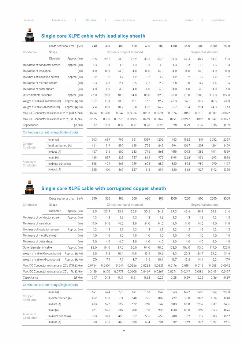
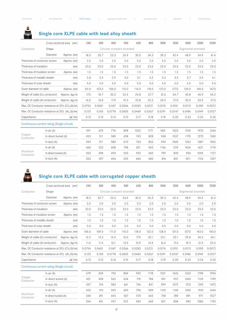
[66 - 69kV ] Single Core Cable
6
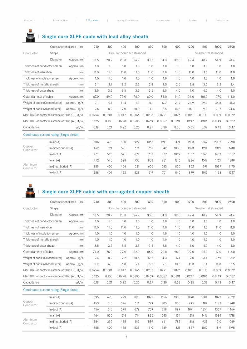
Single core XLPE cable with lead alloy sheath
Single core XLPE cable with corrugated copper sheath
240 300 400 500 630 800 1000 1200 1600 2000 2500
Circular compact stranded Segmental stranded
18.5 20.7 23.3 26.9 30.5 34.3 39.3 42.4 48.9 54.9 61.4
1.0 1.0 1.0 1.0 1.0 1.0 1.0 1.0 1.0 1.0 1.0
11.0 11.0 11.0 11.0 11.0 11.0 11.0 11.0 11.0 11.0 11.0
1.0 1.0 1.0 1.0 1.0 1.0 1.0 1.0 1.0 1.0 1.0
2.1 2.1 2.2 2.3 2.4 2.5 2.6 2.8 3.0 3.2 3.4
3.5 3.5 3.5 3.5 3.5 3.5 4.0 4.0 4.0 4.0 4.0
67.0 69.0 72.0 76.0 80.0 84.0 91.0 94.0 101.0 107.0 114.0
9.1 10.1 11.4 13.1 15.1 17.7 21.2 23.9 29.3 34.8 41.3
7.6 8.2 9.0 10.0 11.1 12.5 14.5 16.1 19.0 21.7 24.6
0.0754 0.0601 0.047 0.0366 0.0283 0.0221 0.0176 0.0151 0.0113 0.009 0.0072
0.125 0.100 0.0778 0.0605 0.0469 0.0367 0.0291 0.0247 0.0186 0.0149 0.0127
0.19 0.21 0.22 0.25 0.27 0.30 0.33 0.35 0.39 0.43 0.47
Conductor
Cross sectional area (mm2)
Shape
Diameter Approx. (mm)
Thickness of conductor screen Approx. (mm)
Thickness of insulation (mm)
Thickness of insulation screen Approx. (mm)
Thickness of metallic sheath (mm)
Thickness of outer sheath (mm)
Outer diameter of cable Approx. (mm)
Weight of cable (Cu conductor) Approx. (/m)
Weight of cable (Al conductor) Approx. (/m)
Max. DC Conductor resistance at 20 (CU, Ω/km)
Max. DC Conductor resistance at 20 (AL, Ω/km)
Capacitance (/km)
606 693 800 927 1067 1211 1471 1603 1867 2082 2290
462 521 591 671 757 842 1000 1073 1214 1321 1418
461 520 591 672 782 877 1027 1107 1265 1433 1557
472 540 628 733 853 981 1216 1286 1519 1721 1888
359 406 464 531 605 683 825 862 991 1097 1175
358 404 462 528 619 701 840 879 1013 1158 1247
Copper Conductor
In air (A)
In direct buried (A)
In duct (A)
Aluminum Conductor
In air (A)
In direct buried (A)
In duct (A)
Continuous current rating (Single circuit)
240 300 400 500 630 800 1000 1200 1600 2000 2500
Circular compact stranded Segmental stranded
18.5 20.7 23.3 26.9 30.5 34.3 39.3 42.4 48.9 54.9 61.4
1.0 1.0 1.0 1.0 1.0 1.0 1.0 1.0 1.0 1.0 1.0
11.0 11.0 11.0 11.0 11.0 11.0 11.0 11.0 11.0 11.0 11.0
1.0 1.0 1.0 1.0 1.0 1.0 1.0 1.0 1.0 1.0 1.0
1.0 1.0 1.0 1.0 1.0 1.0 1.0 1.0 1.0 1.0 1.0
3.5 3.5 3.5 3.5 3.5 3.5 4.0 4.0 4.0 4.0 4.0
74.0 76.0 79.0 82.0 86.0 90.0 96.0 99.0 106.0 112.0 118.0
7.4 8.2 9.2 10.5 12.2 14.3 17.1 19.0 23.4 27.9 33.2
5.9 6.3 6.8 7.4 8.2 9.1 10.5 11.3 13.1 14.8 16.5
0.0754 0.0601 0.047 0.0366 0.0283 0.0221 0.0176 0.0151 0.0113 0.009 0.0072
0.125 0.100 0.0778 0.0605 0.0469 0.0367 0.0291 0.0247 0.0186 0.0149 0.0127
0.19 0.21 0.22 0.25 0.27 0.30 0.33 0.35 0.39 0.43 0.47
Conductor
Cross sectional area (mm2)
Shape
Diameter Approx. (mm)
Thickness of conductor screen Approx. (mm)
Thickness of insulation (mm)
Thickness of insulation screen Approx. (mm)
Thickness of metallic sheath (mm)
Thickness of outer sheath (mm)
Outer diameter of cable Approx. (mm)
Weight of cable (Cu conductor) Approx. (/m)
Weight of cable (Al conductor) Approx. (/m)
Max. DC Conductor resistance at 20 (CU, Ω/km)
Max. DC Conductor resistance at 20 (AL, Ω/km)
Capacitance (/km)
595 678 779 898 1027 1156 1380 1490 1704 1872 2029
453 510 576 651 729 805 935 995 1104 1182 1248
456 513 598 679 769 859 999 1071 1254 1367 1466
464 530 614 714 826 645 1154 1215 1416 1584 1718
354 399 455 519 589 661 785 818 925 1010 1069
355 400 468 535 610 689 821 857 1012 1119 1195
Copper Conductor
In air (A)
In direct buried (A)
In duct (A)
Aluminum Conductor
In air (A)
In direct buried (A)
In duct (A)
Continuous current rating (Single circuit)
Contents | Introduct ion | TECH data | Laying Condit ions | Accessor ies | System | Instal lat ion
7
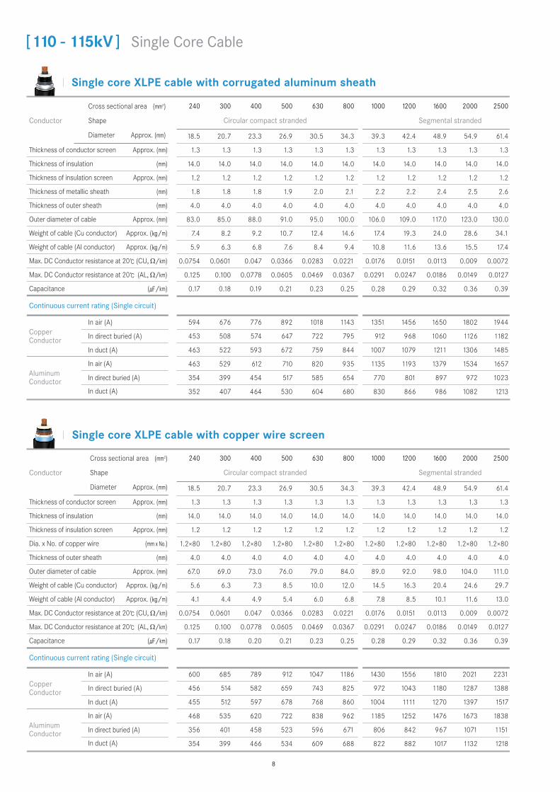
Single core XLPE cable with copper wire screen
Single core XLPE cable with corrugated aluminum sheath
240 300 400 500 630 800 1000 1200 1600 2000 2500
Circular compact stranded Segmental stranded
18.5 20.7 23.3 26.9 30.5 34.3 39.3 42.4 48.9 54.9 61.4
1.3 1.3 1.3 1.3 1.3 1.3 1.3 1.3 1.3 1.3 1.3
14.0 14.0 14.0 14.0 14.0 14.0 14.0 14.0 14.0 14.0 14.0
1.2 1.2 1.2 1.2 1.2 1.2 1.2 1.2 1.2 1.2 1.2
1.8 1.8 1.8 1.9 2.0 2.1 2.2 2.2 2.4 2.5 2.6
4.0 4.0 4.0 4.0 4.0 4.0 4.0 4.0 4.0 4.0 4.0
83.0 85.0 88.0 91.0 95.0 100.0 106.0 109.0 117.0 123.0 130.0
7.4 8.2 9.2 10.7 12.4 14.6 17.4 19.3 24.0 28.6 34.1
5.9 6.3 6.8 7.6 8.4 9.4 10.8 11.6 13.6 15.5 17.4
0.0754 0.0601 0.047 0.0366 0.0283 0.0221 0.0176 0.0151 0.0113 0.009 0.0072
0.125 0.100 0.0778 0.0605 0.0469 0.0367 0.0291 0.0247 0.0186 0.0149 0.0127
0.17 0.18 0.19 0.21 0.23 0.25 0.28 0.29 0.32 0.36 0.39
Conductor
Cross sectional area (mm2)
Shape
Diameter Approx. (mm)
Thickness of conductor screen Approx. (mm)
Thickness of insulation (mm)
Thickness of insulation screen Approx. (mm)
Thickness of metallic sheath (mm)
Thickness of outer sheath (mm)
Outer diameter of cable Approx. (mm)
Weight of cable (Cu conductor) Approx. (/m)
Weight of cable (Al conductor) Approx. (/m)
Max. DC Conductor resistance at 20 (CU, Ω/km)
Max. DC Conductor resistance at 20 (AL, Ω/km)
Capacitance (/km)
594 676 776 892 1018 1143 1351 1456 1650 1802 1944
453 508 574 647 722 795 912 968 1060 1126 1182
463 522 593 672 759 844 1007 1079 1211 1306 1485
463 529 612 710 820 935 1135 1193 1379 1534 1657
354 399 454 517 585 654 770 801 897 972 1023
352 407 464 530 604 680 830 866 986 1082 1213
Copper Conductor
In air (A)
In direct buried (A)
In duct (A)
Aluminum Conductor
In air (A)
In direct buried (A)
In duct (A)
Continuous current rating (Single circuit)
240 300 400 500 630 800 1000 1200 1600 2000 2500
Circular compact stranded Segmental stranded
18.5 20.7 23.3 26.9 30.5 34.3 39.3 42.4 48.9 54.9 61.4
1.3 1.3 1.3 1.3 1.3 1.3 1.3 1.3 1.3 1.3 1.3
14.0 14.0 14.0 14.0 14.0 14.0 14.0 14.0 14.0 14.0 14.0
1.2 1.2 1.2 1.2 1.2 1.2 1.2 1.2 1.2 1.2 1.2
1.2×80 1.2×80 1.2×80 1.2×80 1.2×80 1.2×80 1.2×80 1.2×80 1.2×80 1.2×80 1.2×80
4.0 4.0 4.0 4.0 4.0 4.0 4.0 4.0 4.0 4.0 4.0
67.0 69.0 73.0 76.0 79.0 84.0 89.0 92.0 98.0 104.0 111.0
5.6 6.3 7.3 8.5 10.0 12.0 14.5 16.3 20.4 24.6 29.7
4.1 4.4 4.9 5.4 6.0 6.8 7.8 8.5 10.1 11.6 13.0
0.0754 0.0601 0.047 0.0366 0.0283 0.0221 0.0176 0.0151 0.0113 0.009 0.0072
0.125 0.100 0.0778 0.0605 0.0469 0.0367 0.0291 0.0247 0.0186 0.0149 0.0127
0.17 0.18 0.20 0.21 0.23 0.25 0.28 0.29 0.32 0.36 0.39
Conductor
Cross sectional area (mm2)
Shape
Diameter Approx. (mm)
Thickness of conductor screen Approx. (mm)
Thickness of insulation (mm)
Thickness of insulation screen Approx. (mm)
Dia. x No. of copper wire (mm x No.)
Thickness of outer sheath (mm)
Outer diameter of cable Approx. (mm)
Weight of cable (Cu conductor) Approx. (/m)
Weight of cable (Al conductor) Approx. (/m)
Max. DC Conductor resistance at 20 (CU, Ω/km)
Max. DC Conductor resistance at 20 (AL, Ω/km)
Capacitance (/km)
600 685 789 912 1047 1186 1430 1556 1810 2021 2231
456 514 582 659 743 825 972 1043 1180 1287 1388
455 512 597 678 768 860 1004 1111 1270 1397 1517
468 535 620 722 838 962 1185 1252 1476 1673 1838
356 401 458 523 596 671 806 842 967 1071 1151
354 399 466 534 609 688 822 882 1017 1132 1218
Copper Conductor
In air (A)
In direct buried (A)
In duct (A)
Aluminum Conductor
In air (A)
In direct buried (A)
In duct (A)
Continuous current rating (Single circuit)
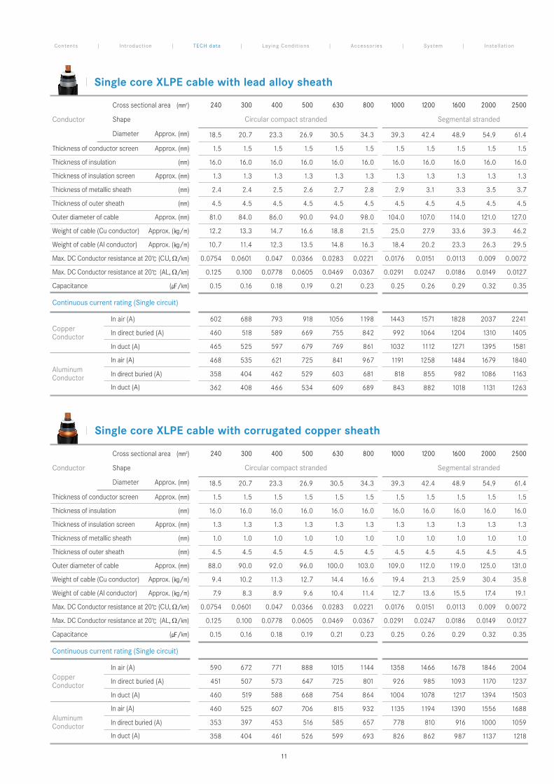
[110 - 115kV ] Single Core Cable
8
Single core XLPE cable with lead alloy sheath
Single core XLPE cable with corrugated copper sheath
591 674 773 891 1018 1147 1363 1472 1685 1852 2008
452 508 574 648 726 802 929 988 1096 1174 1240
463 522 592 672 760 847 1013 1088 1232 1339 1431
461 526 609 708 818 935 1140 1200 1397 1563 1696
353 398 453 517 586 658 780 812 919 1003 1062
360 406 463 530 604 681 832 869 996 1099 1231
Copper Conductor
In air (A)
In direct buried (A)
In duct (A)
Aluminum Conductor
In air (A)
In direct buried (A)
In duct (A)
Continuous current rating (Single circuit)
603 689 795 921 1059 1202 1453 1582 1841 2052 2257
461 519 590 669 756 842 994 1067 1208 1314 1409
457 516 600 683 775 868 1015 1093 1283 1411 1529
469 537 623 727 845 972 1199 1268 1496 1693 1856
358 404 463 529 604 682 820 858 985 1090 1167
355 401 469 537 613 694 830 868 1027 1142 1228
Copper Conductor
In air (A)
In direct buried (A)
In duct (A)
Aluminum Conductor
In air (A)
In direct buried (A)
In duct (A)
Continuous current rating (Single circuit)
240 300 400 500 630 800 1000 1200 1600 2000 2500
Circular compact stranded Segmental stranded
18.5 20.7 23.3 26.9 30.5 34.3 39.3 42.4 48.9 54.9 61.4
1.3 1.3 1.3 1.3 1.3 1.3 1.3 1.3 1.3 1.3 1.3
14.0 14.0 14.0 14.0 14.0 14.0 14.0 14.0 14.0 14.0 14.0
1.2 1.2 1.2 1.2 1.2 1.2 1.2 1.2 1.2 1.2 1.2
2.3 2.3 2.4 2.5 2.6 2.7 2.8 3.0 3.2 3.4 3.6
4.0 4.0 4.0 4.0 4.0 4.0 4.0 4.0 4.0 4.0 4.0
76.0 78.0 81.0 84.0 88.0 92.0 98.0 101.0 108.0 115.0 122.0
10.9 11.9 13.3 15.1 17.2 19.9 23.3 26.1 31.7 37.3 44.0
9.4 10.0 10.9 12.0 13.2 14.7 16.7 18.4 21.4 24.3 27.3
0.0754 0.0601 0.047 0.0366 0.0283 0.0221 0.0176 0.0151 0.0113 0.009 0.0072
0.125 0.100 0.0778 0.0605 0.0469 0.0367 0.0291 0.0247 0.0186 0.0149 0.0127
0.17 0.18 0.19 0.21 0.23 0.25 0.28 0.29 0.32 0.36 0.39
Conductor
Cross sectional area (mm2)
Shape
Diameter Approx. (mm)
Thickness of conductor screen Approx. (mm)
Thickness of insulation (mm)
Thickness of insulation screen Approx. (mm)
Thickness of metallic sheath (mm)
Thickness of outer sheath (mm)
Outer diameter of cable Approx. (mm)
Weight of cable (Cu conductor) Approx. (/m)
Weight of cable (Al conductor) Approx. (/m)
Max. DC Conductor resistance at 20 (CU, Ω/km)
Max. DC Conductor resistance at 20 (AL, Ω/km)
Capacitance (/km)
240 300 400 500 630 800 1000 1200 1600 2000 2500
Circular compact stranded Segmental stranded
18.5 20.7 23.3 26.9 30.5 34.3 39.3 42.4 48.9 54.9 61.4
1.3 1.3 1.3 1.3 1.3 1.3 1.3 1.3 1.3 1.3 1.3
14.0 14.0 14.0 14.0 14.0 14.0 14.0 14.0 14.0 14.0 14.0
1.2 1.2 1.2 1.2 1.2 1.2 1.2 1.2 1.2 1.2 1.2
1.0 1.0 1.0 1.0 1.0 1.0 1.0 1.0 1.0 1.0 1.0
4.0 4.0 4.0 4.0 4.0 4.0 4.0 4.0 4.0 4.0 4.0
82.0 84.0 87.0 90.0 94.0 98.0 103.0 106.0 113.0 119.0 125.0
8.5 9.3 10.4 11.8 13.5 15.6 18.3 20.3 24.7 29.2 34.6
7.0 7.4 7.9 8.7 9.5 10.4 11.7 12.5 14.4 16.2 17.9
0.0754 0.0601 0.047 0.0366 0.0283 0.0221 0.0176 0.0151 0.0113 0.009 0.0072
0.125 0.100 0.0778 0.0605 0.0469 0.0367 0.0291 0.0247 0.0186 0.0149 0.0127
0.17 0.18 0.19 0.21 0.23 0.25 0.28 0.29 0.32 0.36 0.39
Conductor
Cross sectional area (mm2)
Shape
Diameter Approx. (mm)
Thickness of conductor screen Approx. (mm)
Thickness of insulation (mm)
Thickness of insulation screen Approx. (mm)
Thickness of metallic sheath (mm)
Thickness of outer sheath (mm)
Outer diameter of cable Approx. (mm)
Weight of cable (Cu conductor) Approx. (/m)
Weight of cable (Al conductor) Approx. (/m)
Max. DC Conductor resistance at 20 (CU, Ω/km)
Max. DC Conductor resistance at 20 (AL, Ω/km)
Capacitance (/km)
Contents | Introduct ion | TECH data | Laying Condit ions | Accessor ies | System | Instal lat ion
9
Single core XLPE cable with copper wire screen
Single core XLPE cable with corrugated aluminum sheath
240 300 400 500 630 800 1000 1200 1600 2000 2500
Circular compact stranded Segmental stranded
18.5 20.7 23.3 26.9 30.5 34.3 39.3 42.4 48.9 54.9 61.4
1.5 1.5 1.5 1.5 1.5 1.5 1.5 1.5 1.5 1.5 1.5
16.0 16.0 16.0 16.0 16.0 16.0 16.0 16.0 16.0 16.0 16.0
1.3 1.3 1.3 1.3 1.3 1.3 1.3 1.3 1.3 1.3 1.3
1.8 1.9 1.9 2.0 2.1 2.2 2.3 2.3 2.5 2.6 2.7
4.5 4.5 4.5 4.5 4.5 4.5 4.5 4.5 4.5 4.5 4.5
88.0 91.0 93.0 97.0 101.0 106.0 112.0 115.0 123.0 129.0 136.0
8.2 9.1 10.1 11.6 13.4 15.7 18.6 20.5 25.2 29.9 35.5
6.7 7.2 7.7 8.5 9.4 10.5 11.9 12.8 14.9 16.9 18.8
0.0754 0.0601 0.047 0.0366 0.0283 0.0221 0.0176 0.0151 0.0113 0.009 0.0072
0.125 0.100 0.0778 0.0605 0.0469 0.0367 0.0291 0.0247 0.0186 0.0149 0.0127
0.15 0.16 0.18 0.19 0.21 0.23 0.25 0.26 0.29 0.32 0.35
Conductor
Cross sectional area (mm2)
Shape
Diameter Approx. (mm)
Thickness of conductor screen Approx. (mm)
Thickness of insulation (mm)
Thickness of insulation screen Approx. (mm)
Thickness of metallic sheath (mm)
Thickness of outer sheath (mm)
Outer diameter of cable Approx. (mm)
Weight of cable (Cu conductor) Approx. (/m)
Weight of cable (Al conductor) Approx. (/m)
Max. DC Conductor resistance at 20 (CU, Ω/km)
Max. DC Conductor resistance at 20 (AL, Ω/km)
Capacitance (/km)
592 674 773 889 1014 1139 1343 1447 1642 1795 1939
452 507 572 644 720 792 907 962 1055 1122 1178
461 519 589 667 752 861 996 1066 1193 1366 1463
462 527 609 707 816 931 1128 1185 1371 1526 1650
353 398 453 515 583 652 767 798 894 969 1022
359 404 461 526 615 692 821 856 974 1122 1197
Copper Conductor
In air (A)
In direct buried (A)
In duct (A)
Aluminum Conductor
In air (A)
In direct buried (A)
In duct (A)
240 300 400 500 630 800 1000 1200 1600 2000 2500
Circular compact stranded Segmental stranded
18.5 20.7 23.3 26.9 30.5 34.3 39.3 42.4 48.9 54.9 61.4
1.5 1.5 1.5 1.5 1.5 1.5 1.5 1.5 1.5 1.5 1.5
16.0 16.0 16.0 16.0 16.0 16.0 16.0 16.0 16.0 16.0 16.0
1.3 1.3 1.3 1.3 1.3 1.3 1.3 1.3 1.3 1.3 1.3
1.2×80 1.2×80 1.2×80 1.2×80 1.2×80 1.2×80 1.2×80 1.2×80 1.2×80 1.2×80 1.2×80
4.5 4.5 4.5 4.5 4.5 4.5 4.5 4.5 4.5 4.5 4.5
73.0 75.0 78.0 81.0 85.0 89.0 94.0 97.0 104.0 110.0 116.0
6.2 6.9 8.0 9.2 10.8 12.8 15.3 17.1 21.3 25.6 30.8
4.7 5.0 5.5 6.1 6.7 7.6 8.6 9.4 11.0 12.6 14.1
0.0754 0.0601 0.047 0.0366 0.0283 0.0221 0.0176 0.0151 0.0113 0.009 0.0072
0.125 0.100 0.0778 0.0605 0.0469 0.0367 0.0291 0.0247 0.0186 0.0149 0.0127
0.15 0.16 0.18 0.19 0.21 0.23 0.25 0.26 0.29 0.32 0.35
Conductor
Cross sectional area (mm2)
Shape
Diameter Approx. (mm)
Thickness of conductor screen Approx. (mm)
Thickness of insulation (mm)
Thickness of insulation screen Approx. (mm)
Dia. x No. of copper wire (mm x No.)
Thickness of outer sheath (mm)
Outer diameter of cable Approx. (mm)
Weight of cable (Cu conductor) Approx. (/m)
Weight of cable (Al conductor) Approx. (/m)
Max. DC Conductor resistance at 20 (CU, Ω/km)
Max. DC Conductor resistance at 20 (AL, Ω/km)
Capacitance (/km)
599 684 787 910 1045 1183 1424 1550 1803 2014 2225
456 514 583 661 745 829 974 1046 1185 1294 1397
464 523 595 676 765 878 1026 1106 1264 1390 1509
467 533 618 720 835 958 1179 1245 1468 1664 1828
356 401 458 524 597 673 807 844 970 1075 1156
361 407 465 532 607 686 839 878 1013 1127 1260
Copper Conductor
In air (A)
In direct buried (A)
In duct (A)
Aluminum Conductor
In air (A)
In direct buried (A)
In duct (A)
Continuous current rating (Single circuit)
Continuous current rating (Single circuit)
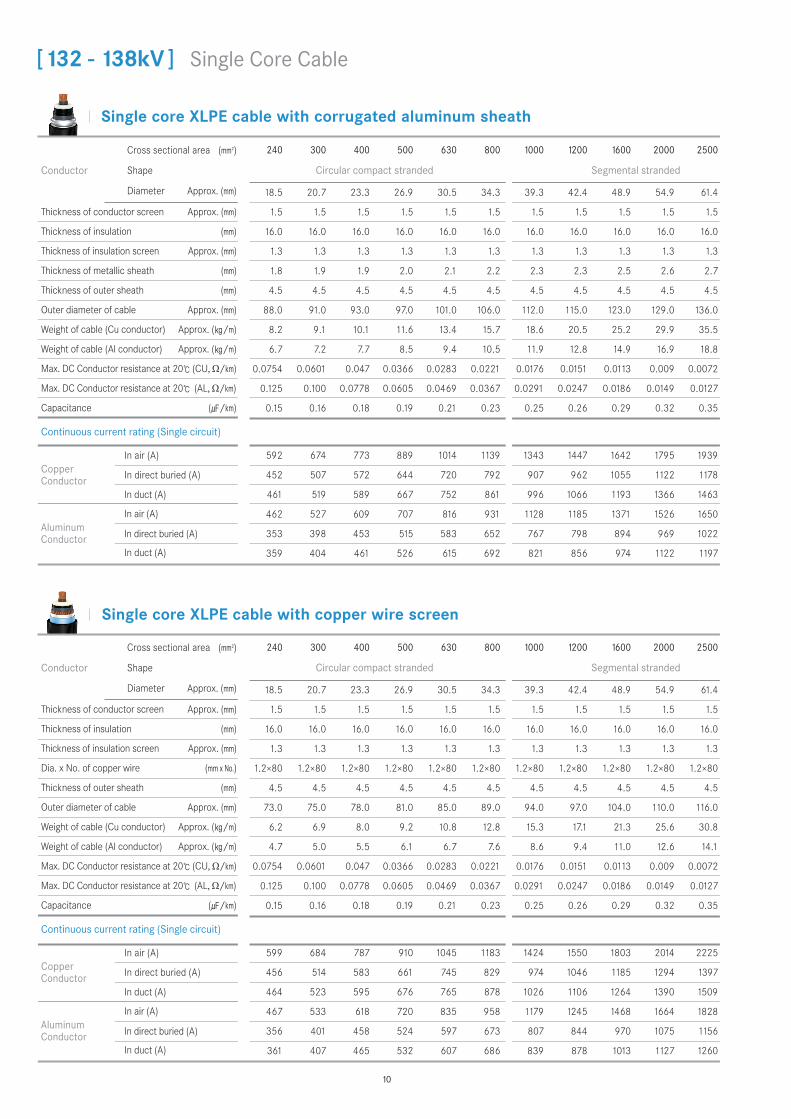
[132 - 138kV ] Single Core Cable
10
Single core XLPE cable with lead alloy sheath
Single core XLPE cable with corrugated copper sheath
602 688 793 918 1056 1198 1443 1571 1828 2037 2241
460 518 589 669 755 842 992 1064 1204 1310 1405
465 525 597 679 769 861 1032 1112 1271 1395 1581
468 535 621 725 841 967 1191 1258 1484 1679 1840
358 404 462 529 603 681 818 855 982 1086 1163
362 408 466 534 609 689 843 882 1018 1131 1263
Copper Conductor
In air (A)
In direct buried (A)
In duct (A)
Aluminum Conductor
In air (A)
In direct buried (A)
In duct (A)
240 300 400 500 630 800 1000 1200 1600 2000 2500
Circular compact stranded Segmental stranded
18.5 20.7 23.3 26.9 30.5 34.3 39.3 42.4 48.9 54.9 61.4
1.5 1.5 1.5 1.5 1.5 1.5 1.5 1.5 1.5 1.5 1.5
16.0 16.0 16.0 16.0 16.0 16.0 16.0 16.0 16.0 16.0 16.0
1.3 1.3 1.3 1.3 1.3 1.3 1.3 1.3 1.3 1.3 1.3
2.4 2.4 2.5 2.6 2.7 2.8 2.9 3.1 3.3 3.5 3.7
4.5 4.5 4.5 4.5 4.5 4.5 4.5 4.5 4.5 4.5 4.5
81.0 84.0 86.0 90.0 94.0 98.0 104.0 107.0 114.0 121.0 127.0
12.2 13.3 14.7 16.6 18.8 21.5 25.0 27.9 33.6 39.3 46.2
10.7 11.4 12.3 13.5 14.8 16.3 18.4 20.2 23.3 26.3 29.5
0.0754 0.0601 0.047 0.0366 0.0283 0.0221 0.0176 0.0151 0.0113 0.009 0.0072
0.125 0.100 0.0778 0.0605 0.0469 0.0367 0.0291 0.0247 0.0186 0.0149 0.0127
0.15 0.16 0.18 0.19 0.21 0.23 0.25 0.26 0.29 0.32 0.35
Conductor
Cross sectional area (mm2)
Shape
Diameter Approx. (mm)
Thickness of conductor screen Approx. (mm)
Thickness of insulation (mm)
Thickness of insulation screen Approx. (mm)
Thickness of metallic sheath (mm)
Thickness of outer sheath (mm)
Outer diameter of cable Approx. (mm)
Weight of cable (Cu conductor) Approx. (/m)
Weight of cable (Al conductor) Approx. (/m)
Max. DC Conductor resistance at 20 (CU, Ω/km)
Max. DC Conductor resistance at 20 (AL, Ω/km)
Capacitance (/km)
240 300 400 500 630 800 1000 1200 1600 2000 2500
Circular compact stranded Segmental stranded
18.5 20.7 23.3 26.9 30.5 34.3 39.3 42.4 48.9 54.9 61.4
1.5 1.5 1.5 1.5 1.5 1.5 1.5 1.5 1.5 1.5 1.5
16.0 16.0 16.0 16.0 16.0 16.0 16.0 16.0 16.0 16.0 16.0
1.3 1.3 1.3 1.3 1.3 1.3 1.3 1.3 1.3 1.3 1.3
1.0 1.0 1.0 1.0 1.0 1.0 1.0 1.0 1.0 1.0 1.0
4.5 4.5 4.5 4.5 4.5 4.5 4.5 4.5 4.5 4.5 4.5
88.0 90.0 92.0 96.0 100.0 103.0 109.0 112.0 119.0 125.0 131.0
9.4 10.2 11.3 12.7 14.4 16.6 19.4 21.3 25.9 30.4 35.8
7.9 8.3 8.9 9.6 10.4 11.4 12.7 13.6 15.5 17.4 19.1
0.0754 0.0601 0.047 0.0366 0.0283 0.0221 0.0176 0.0151 0.0113 0.009 0.0072
0.125 0.100 0.0778 0.0605 0.0469 0.0367 0.0291 0.0247 0.0186 0.0149 0.0127
0.15 0.16 0.18 0.19 0.21 0.23 0.25 0.26 0.29 0.32 0.35
Conductor
Cross sectional area (mm2)
Shape
Diameter Approx. (mm)
Thickness of conductor screen Approx. (mm)
Thickness of insulation (mm)
Thickness of insulation screen Approx. (mm)
Thickness of metallic sheath (mm)
Thickness of outer sheath (mm)
Outer diameter of cable Approx. (mm)
Weight of cable (Cu conductor) Approx. (/m)
Weight of cable (Al conductor) Approx. (/m)
Max. DC Conductor resistance at 20 (CU, Ω/km)
Max. DC Conductor resistance at 20 (AL, Ω/km)
Capacitance (/km)
590 672 771 888 1015 1144 1358 1466 1678 1846 2004
451 507 573 647 725 801 926 985 1093 1170 1237
460 519 588 668 754 864 1004 1078 1217 1394 1503
460 525 607 706 815 932 1135 1194 1390 1556 1688
353 397 453 516 585 657 778 810 916 1000 1059
358 404 461 526 599 693 826 862 987 1137 1218
Copper Conductor
In air (A)
In direct buried (A)
In duct (A)
Aluminum Conductor
In air (A)
In direct buried (A)
In duct (A)
Continuous current rating (Single circuit)
Continuous current rating (Single circuit)
Contents | Introduct ion | TECH data | Laying Condit ions | Accessor ies | System | Instal lat ion
11
Single core XLPE cable with copper wire screen
Single core XLPE cable with corrugated aluminum sheath
240 300 400 500 630 800 1000 1200 1600 2000 2500
Circular compact stranded Segmental stranded
18.5 20.7 23.3 26.9 30.5 34.3 39.3 42.4 48.9 54.9 61.4
1.5 1.5 1.5 1.5 1.5 1.5 1.5 1.5 1.5 1.5 1.5
17.0 17.0 17.0 17.0 17.0 17.0 17.0 17.0 17.0 17.0 17.0
1.3 1.3 1.3 1.3 1.3 1.3 1.3 1.3 1.3 1.3 1.3
1.9 1.9 2.0 2.0 2.1 2.2 2.3 2.4 2.5 2.6 2.7
4.5 4.5 4.5 4.5 4.5 4.5 4.5 4.5 4.5 4.5 4.5
91.0 93.0 96.0 99.0 103.0 108.0 114.0 118.0 125.0 131.0 138.0
8.6 9.4 10.5 11.9 13.8 16.0 18.9 21.0 25.6 30.3 35.9
7.1 7.5 8.1 8.8 9.7 10.8 12.2 13.3 15.3 17.3 19.2
0.0754 0.0601 0.047 0.0366 0.0283 0.0221 0.0176 0.0151 0.0113 0.009 0.0072
0.125 0.100 0.0778 0.0605 0.0469 0.0367 0.0291 0.0247 0.0186 0.0149 0.0127
0.15 0.16 0.17 0.18 0.20 0.22 0.24 0.25 0.28 0.30 0.33
Conductor
Cross sectional area (mm2)
Shape
Diameter Approx. (mm)
Thickness of conductor screen Approx. (mm)
Thickness of insulation (mm)
Thickness of insulation screen Approx. (mm)
Thickness of metallic sheath (mm)
Thickness of outer sheath (mm)
Outer diameter of cable Approx. (mm)
Weight of cable (Cu conductor) Approx. (/m)
Weight of cable (Al conductor) Approx. (/m)
Max. DC Conductor resistance at 20 (CU, Ω/km)
Max. DC Conductor resistance at 20 (AL, Ω/km)
Capacitance (/km)
591 672 771 887 1011 1136 1339 1440 1637 1791 1935
451 506 571 643 718 790 904 956 1052 1118 1175
460 517 586 681 769 857 991 1058 1249 1358 1453
461 526 608 705 814 928 1124 1180 1366 1521 1645
353 397 452 514 582 651 765 794 892 967 1019
358 403 460 525 611 689 817 851 1012 1116 1190
Copper Conductor
In air (A)
In direct buried (A)
In duct (A)
Aluminum Conductor
In air (A)
In direct buried (A)
In duct (A)
240 300 400 500 630 800 1000 1200 1600 2000 2500
Circular compact stranded Segmental stranded
18.5 20.7 23.3 26.9 30.5 34.3 39.3 42.4 48.9 54.9 61.4
1.5 1.5 1.5 1.5 1.5 1.5 1.5 1.5 1.5 1.5 1.5
17.0 17.0 17.0 17.0 17.0 17.0 17.0 17.0 17.0 17.0 17.0
1.3 1.3 1.3 1.3 1.3 1.3 1.3 1.3 1.3 1.3 1.3
1.2×80 1.2×80 1.2×80 1.2×80 1.2×80 1.2×80 1.2×80 1.2×80 1.2×80 1.2×80 1.2×80
4.5 4.5 4.5 4.5 4.5 4.5 4.5 4.5 4.5 4.5 4.5
75.0 77.0 80.0 83.0 87.0 91.0 96.0 99.0 106.0 112.0 118.0
6.4 7.2 8.2 9.4 11.0 13.0 15.6 17.4 21.6 25.9 31.1
4.9 5.3 5.8 6.3 7.0 7.9 8.9 9.7 11.3 12.9 14.4
0.0754 0.0601 0.047 0.0366 0.0283 0.0221 0.0176 0.0151 0.0113 0.009 0.0072
0.125 0.100 0.0778 0.0605 0.0469 0.0367 0.0291 0.0247 0.0186 0.0149 0.0127
0.15 0.16 0.17 0.18 0.20 0.22 0.24 0.25 0.28 0.30 0.33
Conductor
Cross sectional area (mm2)
Shape
Diameter Approx. (mm)
Thickness of conductor screen Approx. (mm)
Thickness of insulation (mm)
Thickness of insulation screen Approx. (mm)
Dia. x No. of copper wire (mm x No.)
Thickness of outer sheath (mm)
Outer diameter of cable Approx. (mm)
Weight of cable (Cu conductor) Approx. (/m)
Weight of cable (Al conductor) Approx. (/m)
Max. DC Conductor resistance at 20 (CU, Ω/km)
Max. DC Conductor resistance at 20 (AL, Ω/km)
Capacitance (/km)
598 683 786 908 1043 1182 1422 1547 1800 2012 2223
457 514 583 661 746 830 975 1047 1186 1296 1400
453 510 594 675 764 855 1025 1104 1262 1387 1576
466 532 617 719 833 957 1177 1243 1465 1660 1824
356 401 459 524 597 674 808 845 971 1077 1158
352 397 464 531 606 685 838 877 1012 1125 1258
Copper Conductor
In air (A)
In direct buried (A)
In duct (A)
Aluminum Conductor
In air (A)
In direct buried (A)
In duct (A)
Continuous current rating (Single circuit)
Continuous current rating (Single circuit)
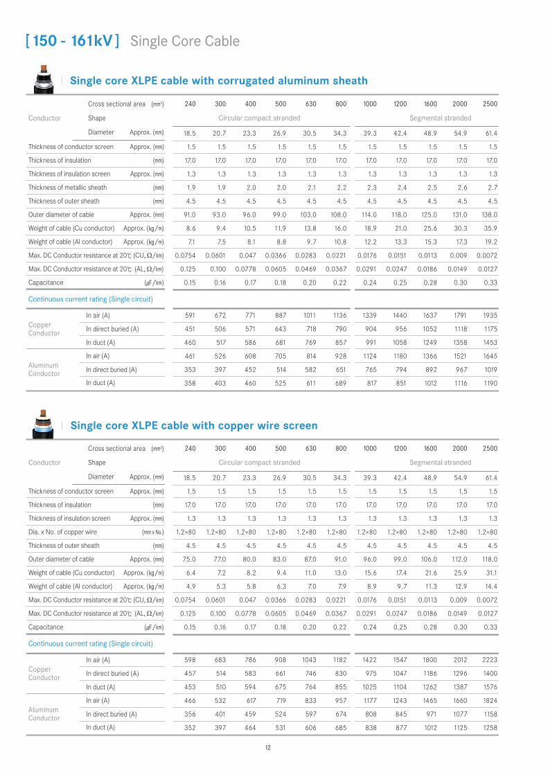
[150 - 161kV ] Single Core Cable
12
Single core XLPE cable with lead alloy sheath
Single core XLPE cable with corrugated copper sheath
240 300 400 500 630 800 1000 1200 1600 2000 2500
Circular compact stranded Segmental stranded
18.5 20.7 23.3 26.9 30.5 34.3 39.3 42.4 48.9 54.9 61.4
1.5 1.5 1.5 1.5 1.5 1.5 1.5 1.5 1.5 1.5 1.5
17.0 17.0 17.0 17.0 17.0 17.0 17.0 17.0 17.0 17.0 17.0
1.3 1.3 1.3 1.3 1.3 1.3 1.3 1.3 1.3 1.3 1.3
2.4 2.5 2.6 2.7 2.8 2.9 3.0 3.2 3.4 3.6 3.8
4.5 4.5 4.5 4.5 4.5 4.5 4.5 4.5 4.5 4.5 4.5
83.0 86.0 89.0 92.0 96.0 100.0 106.0 109.0 116.0 123.0 130.0
12.8 13.9 15.3 17.2 19.4 22.2 25.7 28.6 34.4 40.2 47.0
11.3 12.0 12.9 14.1 15.4 17.0 19.1 20.9 24.1 27.2 30.3
0.0754 0.0601 0.047 0.0366 0.0283 0.0221 0.0176 0.0151 0.0113 0.009 0.0072
0.125 0.100 0.0778 0.0605 0.0469 0.0367 0.0291 0.0247 0.0186 0.0149 0.0127
0.15 0.16 0.17 0.18 0.20 0.22 0.24 0.25 0.28 0.30 0.33
Conductor
Cross sectional area (mm2)
Shape
Diameter Approx. (mm)
Thickness of conductor screen Approx. (mm)
Thickness of insulation (mm)
Thickness of insulation screen Approx. (mm)
Thickness of metallic sheath (mm)
Thickness of outer sheath (mm)
Outer diameter of cable Approx. (mm)
Weight of cable (Cu conductor) Approx. (/m)
Weight of cable (Al conductor) Approx. (/m)
Max. DC Conductor resistance at 20 (CU, Ω/km)
Max. DC Conductor resistance at 20 (AL, Ω/km)
Capacitance (/km)
601 686 791 916 1053 1195 1438 1565 1820 2029 2231
459 518 588 668 754 841 989 1061 1200 1305 1399
464 523 595 677 767 858 1028 1108 1264 1387 1572
467 534 620 723 839 965 1187 1254 1478 1672 1832
357 403 461 528 602 680 816 853 979 1083 1159
361 407 465 532 607 687 840 879 1013 1126 1257
Copper Conductor
In air (A)
In direct buried (A)
In duct (A)
Aluminum Conductor
In air (A)
In direct buried (A)
In duct (A)
240 300 400 500 630 800 1000 1200 1600 2000 2500
Circular compact stranded Segmental stranded
18.5 20.7 23.3 26.9 30.5 34.3 39.3 42.4 48.9 54.9 61.4
1.5 1.5 1.5 1.5 1.5 1.5 1.5 1.5 1.5 1.5 1.5
17.0 17.0 17.0 17.0 17.0 17.0 17.0 17.0 17.0 17.0 17.0
1.3 1.3 1.3 1.3 1.3 1.3 1.3 1.3 1.3 1.3 1.3
1.0 1.0 1.0 1.0 1.0 1.0 1.0 1.0 1.0 1.0 1.0
4.5 4.5 4.5 4.5 4.5 4.5 4.5 4.5 4.5 4.5 4.5
90.0 92.0 94.0 98.0 102.0 105.0 111.0 114.0 121.0 127.0 133.0
9.7 10.5 11.6 13.0 14.8 16.9 19.7 21.7 26.3 30.8 36.3
8.2 8.6 9.2 9.9 10.8 11.7 13.1 14.0 15.9 17.8 19.6
0.0754 0.0601 0.047 0.0366 0.0283 0.0221 0.0176 0.0151 0.0113 0.009 0.0072
0.125 0.100 0.0778 0.0605 0.0469 0.0367 0.0291 0.0247 0.0186 0.0149 0.0127
0.15 0.16 0.17 0.18 0.20 0.22 0.24 0.25 0.28 0.30 0.33
Conductor
Cross sectional area (mm2)
Shape
Diameter Approx. (mm)
Thickness of conductor screen Approx. (mm)
Thickness of insulation (mm)
Thickness of insulation screen Approx. (mm)
Thickness of metallic sheath (mm)
Thickness of outer sheath (mm)
Outer diameter of cable Approx. (mm)
Weight of cable (Cu conductor) Approx. (/m)
Weight of cable (Al conductor) Approx. (/m)
Max. DC Conductor resistance at 20 (CU, Ω/km)
Max. DC Conductor resistance at 20 (AL, Ω/km)
Capacitance (/km)
589 671 770 886 1013 1141 1353 1462 1673 1840 1998
451 506 572 645 724 799 923 982 1089 1166 1233
459 517 587 665 751 861 1000 1072 1210 1386 1493
460 524 606 704 813 930 1131 1190 1385 1550 1683
352 396 452 515 584 655 776 808 913 996 1055
357 402 459 525 597 691 822 858 982 1131 1211
Copper Conductor
In air (A)
In direct buried (A)
In duct (A)
Aluminum Conductor
In air (A)
In direct buried (A)
In duct (A)
Continuous current rating (Single circuit)
Continuous current rating (Single circuit)
Contents | Introduct ion | TECH data | Laying Condit ions | Accessor ies | System | Instal lat ion
13
Single core XLPE cable with copper wire screen
Single core XLPE cable with corrugated aluminum sheath
240 300 400 500 630 800 1000 1200 1600 2000 2500
Circular compact stranded Segmental stranded
18.5 20.7 23.3 26.9 30.5 34.3 39.3 42.4 48.9 54.9 61.4
2.0 2.0 2.0 2.0 2.0 2.0 2.0 2.0 2.0 2.0 2.0
21.0 21.0 21.0 21.0 21.0 21.0 21.0 21.0 21.0 21.0 21.0
1.5 1.5 1.5 1.5 1.5 1.5 1.5 1.5 1.5 1.5 1.5
2.1 2.1 2.2 2.2 2.3 2.4 2.5 2.5 2.7 2.8 2.9
5.0 5.0 5.0 5.0 5.0 5.0 5.0 5.0 5.0 5.0 5.0
104.0 106.0 110.0 113.0 117.0 122.0 128.0 131.0 139.0 145.0 152.0
10.7 11.6 12.8 14.3 16.2 18.6 21.6 23.6 28.6 33.4 39.1
9.3 9.7 10.4 11.2 12.2 13.4 14.9 15.9 18.2 20.4 22.4
0.0754 0.0601 0.047 0.0366 0.0283 0.0221 0.0176 0.0151 0.0113 0.009 0.0072
0.125 0.100 0.0778 0.0605 0.0469 0.0367 0.0291 0.0247 0.0186 0.0149 0.0127
0.13 0.14 0.15 0.16 0.18 0.19 0.21 0.22 0.24 0.26 0.28
Conductor
Cross sectional area (mm2)
Shape
Diameter Approx. (mm)
Thickness of conductor screen Approx. (mm)
Thickness of insulation (mm)
Thickness of insulation screen Approx. (mm)
Thickness of metallic sheath (mm)
Thickness of outer sheath (mm)
Outer diameter of cable Approx. (mm)
Weight of cable (Cu conductor) Approx. (/m)
Weight of cable (Al conductor) Approx. (/m)
Max. DC Conductor resistance at 20 (CU, Ω/km)
Max. DC Conductor resistance at 20 (AL, Ω/km)
Capacitance (/km)
584 664 761 874 996 1119 1315 1417 1612 1766 1913
447 501 564 635 709 780 889 942 1035 1102 1160
462 520 589 667 752 836 1004 1077 1211 1363 1464
456 520 600 695 801 914 1104 1160 1343 1497 1621
350 394 448 509 575 643 754 784 879 953 1006
359 405 462 527 599 674 827 864 985 1119 1195
Copper Conductor
In air (A)
In direct buried (A)
In duct (A)
Aluminum Conductor
In air (A)
In direct buried (A)
In duct (A)
240 300 400 500 630 800 1000 1200 1600 2000 2500
Circular compact stranded Segmental stranded
18.5 20.7 23.3 26.9 30.5 34.3 39.3 42.4 48.9 54.9 61.4
2.0 2.0 2.0 2.0 2.0 2.0 2.0 2.0 2.0 2.0 2.0
21.0 21.0 21.0 21.0 21.0 21.0 21.0 21.0 21.0 21.0 21.0
1.5 1.5 1.5 1.5 1.5 1.5 1.5 1.5 1.5 1.5 1.5
1.2×80 1.2×80 1.2×80 1.2×80 1.2×80 1.2×80 1.2×80 1.2×80 1.2×80 1.2×80 1.2×80
5.0 5.0 5.0 5.0 5.0 5.0 5.0 5.0 5.0 5.0 5.0
85.0 87.0 90.0 93.0 97.0 101.0 106.0 109.0 116.0 122.0 128.0
7.6 8.4 9.5 10.7 12.4 14.5 17.1 19.0 23.3 27.7 33.0
6.1 6.5 7.1 7.6 8.4 9.3 10.4 11.2 13.0 14.7 16.3
0.0754 0.0601 0.047 0.0366 0.0283 0.0221 0.0176 0.0151 0.0113 0.009 0.0072
0.125 0.100 0.0778 0.0605 0.0469 0.0367 0.0291 0.0247 0.0186 0.0149 0.0127
0.13 0.14 0.15 0.16 0.17 0.19 0.21 0.22 0.24 0.26 0.28
Conductor
Cross sectional area (mm2)
Shape
Diameter Approx. (mm)
Thickness of conductor screen Approx. (mm)
Thickness of insulation (mm)
Thickness of insulation screen Approx. (mm)
Dia. x No. of copper wire (mm x No.)
Thickness of outer sheath (mm)
Outer diameter of cable Approx. (mm)
Weight of cable (Cu conductor) Approx. (/m)
Weight of cable (Al conductor) Approx. (/m)
Max. DC Conductor resistance at 20 (CU, Ω/km)
Max. DC Conductor resistance at 20 (AL, Ω/km)
Capacitance (/km)
595 679 781 903 1037 1176 1410 1534 1787 1998 2210
457 515 584 663 749 834 978 1051 1193 1305 1413
461 520 590 671 777 871 1017 1095 1251 1431 1562
463 529 613 713 827 950 1165 1230 1450 1644 1807
357 402 459 525 599 676 810 847 975 1082 1165
358 404 462 528 615 696 832 871 1004 1157 1249
Copper Conductor
In air (A)
In direct buried (A)
In duct (A)
Aluminum Conductor
In air (A)
In direct buried (A)
In duct (A)
Continuous current rating (Single circuit)
Continuous current rating (Single circuit)
[220 - 230kV ] Single Core Cable
14
Single core XLPE cable with lead alloy sheath
Single core XLPE cable with corrugated copper sheath
240 300 400 500 630 800 1000 1200 1600 2000 2500
Circular compact stranded Segmental stranded
18.5 20.7 23.3 26.9 30.5 34.3 39.3 42.4 48.9 54.9 61.4
2.0 2.0 2.0 2.0 2.0 2.0 2.0 2.0 2.0 2.0 2.0
21.0 21.0 21.0 21.0 21.0 21.0 21.0 21.0 21.0 21.0 21.0
1.5 1.5 1.5 1.5 1.5 1.5 1.5 1.5 1.5 1.5 1.5
2.7 2.7 2.8 2.9 3.0 3.1 3.2 3.4 3.6 3.8 4.0
5.0 5.0 5.0 5.0 5.0 5.0 5.0 5.0 5.0 5.0 5.0
97.0 99.0 102.0 106.0 109.0 113.0 119.0 123.0 130.0 136.0 143.0
16.1 17.3 18.9 20.9 23.3 26.2 30.0 33.0 39.1 45.1 52.2
14.6 15.4 16.5 17.8 19.3 21.0 23.3 25.3 28.7 32.1 35.5
0.0754 0.0601 0.047 0.0366 0.0283 0.0221 0.0176 0.0151 0.0113 0.009 0.0072
0.125 0.100 0.0778 0.0605 0.0469 0.0367 0.0291 0.0247 0.0186 0.0149 0.0127
0.13 0.14 0.15 0.16 0.18 0.19 0.21 0.22 0.24 0.26 0.28
Conductor
Cross sectional area (mm2)
Shape
Diameter Approx. (mm)
Thickness of conductor screen Approx. (mm)
Thickness of insulation (mm)
Thickness of insulation screen Approx. (mm)
Thickness of metallic sheath (mm)
Thickness of outer sheath (mm)
Outer diameter of cable Approx. (mm)
Weight of cable (Cu conductor) Approx. (/m)
Weight of cable (Al conductor) Approx. (/m)
Max. DC Conductor resistance at 20 (CU, Ω/km)
Max. DC Conductor resistance at 20 (AL, Ω/km)
Capacitance (/km)
595 679 782 904 1039 1179 1413 1537 1786 1989 2187
456 514 584 663 749 835 978 1048 1184 1287 1379
458 516 586 680 771 863 1008 1084 1281 1409 1529
463 528 612 713 827 950 1166 1230 1448 1637 1792
355 401 458 524 597 674 807 843 967 1068 1142
356 401 458 535 610 690 825 862 1025 1140 1226
Copper Conductor
In air (A)
In direct buried (A)
In duct (A)
Aluminum Conductor
In air (A)
In direct buried (A)
In duct (A)
240 300 400 500 630 800 1000 1200 1600 2000 2500
Circular compact stranded Segmental stranded
18.5 20.7 23.3 26.9 30.5 34.3 39.3 42.4 48.9 54.9 61.4
2.0 2.0 2.0 2.0 2.0 2.0 2.0 2.0 2.0 2.0 2.0
21.0 21.0 21.0 21.0 21.0 21.0 21.0 21.0 21.0 21.0 21.0
1.5 1.5 1.5 1.5 1.5 1.5 1.5 1.5 1.5 1.5 1.5
1.0 1.0 1.0 1.0 1.0 1.0 1.0 1.0 1.0 1.0 1.0
5.0 5.0 5.0 5.0 5.0 5.0 5.0 5.0 5.0 5.0 5.0
102.0 105.0 107.0 111.0 114.0 118.0 124.0 127.0 133.0 139.0 146.0
11.8 12.6 13.8 15.3 17.1 19.3 22.3 24.3 28.9 33.6 39.2
10.3 10.7 11.4 12.2 13.1 14.1 15.6 16.6 18.6 20.6 22.5
0.0754 0.0601 0.047 0.0366 0.0283 0.0221 0.0176 0.0151 0.0113 0.009 0.0072
0.125 0.100 0.0778 0.0605 0.0469 0.0367 0.0291 0.0247 0.0186 0.0149 0.0127
0.13 0.14 0.15 0.16 0.18 0.19 0.21 0.22 0.24 0.26 0.28
Conductor
Cross sectional area (mm2)
Shape
Diameter Approx. (mm)
Thickness of conductor screen Approx. (mm)
Thickness of insulation (mm)
Thickness of insulation screen Approx. (mm)
Thickness of metallic sheath (mm)
Thickness of outer sheath (mm)
Outer diameter of cable Approx. (mm)
Weight of cable (Cu conductor) Approx. (/m)
Weight of cable (Al conductor) Approx. (/m)
Max. DC Conductor resistance at 20 (CU, Ω/km)
Max. DC Conductor resistance at 20 (AL, Ω/km)
Capacitance (/km)
582 663 760 875 999 1126 1331 1438 1646 1812 1970
451 502 567 639 717 792 911 968 1073 1149 1215
452 519 589 669 755 842 974 1088 1232 1343 1498
455 518 599 694 802 916 1112 1170 1361 1523 1654
350 394 448 511 579 649 766 797 901 983 1041
352 404 462 527 600 677 804 869 996 1101 1214
Copper Conductor
In air (A)
In direct buried (A)
In duct (A)
Aluminum Conductor
In air (A)
In direct buried (A)
In duct (A)
Continuous current rating (Single circuit)
Continuous current rating (Single circuit)
Contents | Introduct ion | TECH data | Laying Condit ions | Accessor ies | System | Instal lat ion
15
Single core XLPE cable with copper wire screen
Single core XLPE cable with corrugated aluminum sheath
240 300 400 500 630 800 1000 1200 1600 2000 2500
Circular compact stranded Segmental stranded
18.5 20.7 23.3 26.9 30.5 34.3 39.3 42.4 48.9 54.9 61.4
2.0 2.0 2.0 2.0 2.0 2.0 2.0 2.0 2.0 2.0 2.0
23.0 23.0 23.0 23.0 23.0 23.0 23.0 23.0 23.0 23.0 23.0
1.5 1.5 1.5 1.5 1.5 1.5 1.5 1.5 1.5 1.5 1.5
2.1 2.2 2.2 2.3 2.4 2.5 2.6 2.6 2.8 2.9 3.0
5.0 5.0 5.0 5.0 5.0 5.0 5.0 5.0 5.0 5.0 5.0
108.0 111.0 114.0 118.0 122.0 126.0 133.0 136.0 143.0 150.0 157.0
11.4 12.4 13.5 15.2 17.1 19.5 22.6 24.6 29.6 34.5 40.3
9.9 10.5 11.1 12.1 13.1 14.3 15.9 16.9 19.3 21.4 23.6
0.0754 0.0601 0.047 0.0366 0.0283 0.0221 0.0176 0.0151 0.0113 0.009 0.0072
0.125 0.100 0.0778 0.0605 0.0469 0.0367 0.0291 0.0247 0.0186 0.0149 0.0127
0.13 0.13 0.14 0.15 0.17 0.18 0.19 0.20 0.23 0.24 0.26
Conductor
Cross sectional area (mm2)
Shape
Diameter Approx. (mm)
Thickness of conductor screen Approx. (mm)
Thickness of insulation (mm)
Thickness of insulation screen Approx. (mm)
Thickness of metallic sheath (mm)
Thickness of outer sheath (mm)
Outer diameter of cable Approx. (mm)
Weight of cable (Cu conductor) Approx. (/m)
Weight of cable (Al conductor) Approx. (/m)
Max. DC Conductor resistance at 20 (CU, Ω/km)
Max. DC Conductor resistance at 20 (AL, Ω/km)
Capacitance (/km)
580 660 755 868 989 1111 1305 1407 1600 1754 1901
444 497 560 630 703 772 880 932 1023 1089 1147
457 514 583 660 743 857 991 1061 1192 1341 1437
453 516 596 690 795 907 1095 1151 1332 1485 1609
348 391 444 505 571 637 747 776 869 943 995
356 401 457 521 592 689 817 852 971 1102 1176
Copper Conductor
In air (A)
In direct buried (A)
In duct (A)
Aluminum Conductor
In air (A)
In direct buried (A)
In duct (A)
240 300 400 500 630 800 1000 1200 1600 2000 2500
Circular compact stranded Segmental stranded
18.5 20.7 23.3 26.9 30.5 34.3 39.3 42.4 48.9 54.9 61.4
2.0 2.0 2.0 2.0 2.0 2.0 2.0 2.0 2.0 2.0 2.0
23.0 23.0 23.0 23.0 23.0 23.0 23.0 23.0 23.0 23.0 23.0
1.5 1.5 1.5 1.5 1.5 1.5 1.5 1.5 1.5 1.5 1.5
1.2×80 1.2×80 1.2×80 1.2×80 1.2×80 1.2×80 1.2×80 1.2×80 1.2×80 1.2×80 1.2×80
5.0 5.0 5.0 5.0 5.0 5.0 5.0 5.0 5.0 5.0 5.0
89.0 91.0 94.0 97.0 101.0 105.0 110.0 113.0 120.0 126.0 132.0
8.1 8.9 10.0 11.3 13.0 15.1 17.7 19.6 24.0 28.4 33.7
6.6 7.0 7.6 8.2 8.9 9.9 11.1 11.9 13.7 15.4 17.0
0.0754 0.0601 0.047 0.0366 0.0283 0.0221 0.0176 0.0151 0.0113 0.009 0.0072
0.125 0.100 0.0778 0.0605 0.0469 0.0367 0.0291 0.0247 0.0186 0.0149 0.0127
0.12 0.13 0.14 0.15 0.16 0.18 0.19 0.20 0.22 0.24 0.26
Conductor
Cross sectional area (mm2)
Shape
Diameter Approx. (mm)
Thickness of conductor screen Approx. (mm)
Thickness of insulation (mm)
Thickness of insulation screen Approx. (mm)
Dia. x No. of copper wire (mm x No.)
Thickness of outer sheath (mm)
Outer diameter of cable Approx. (mm)
Weight of cable (Cu conductor) Approx. (/m)
Weight of cable (Al conductor) Approx. (/m)
Max. DC Conductor resistance at 20 (CU, Ω/km)
Max. DC Conductor resistance at 20 (AL, Ω/km)
Capacitance (/km)
589 672 773 893 1026 1163 1394 1516 1766 1975 2185
451 508 576 653 737 853 961 1031 1170 1279 1382
453 511 580 673 762 821 995 1070 1266 1396 1520
459 524 607 706 818 939 1151 1215 1432 1623 1783
352 396 453 517 589 664 795 831 955 1059 1139
353 397 453 529 604 682 814 851 1013 1128 1261
Copper Conductor
In air (A)
In direct buried (A)
In duct (A)
Aluminum Conductor
In air (A)
In direct buried (A)
In duct (A)
Continuous current rating (Single circuit)
Continuous current rating (Single circuit)
[275 - 287kV ] Single Core Cable
16
Single core XLPE cable with lead alloy sheath
Single core XLPE cable with corrugated copper sheath
240 300 400 500 630 800 1000 1200 1600 2000 2500
Circular compact stranded Segmental stranded
18.5 20.7 23.3 26.9 30.5 34.3 39.3 42.4 48.9 54.9 61.4
2.0 2.0 2.0 2.0 2.0 2.0 2.0 2.0 2.0 2.0 2.0
23.0 23.0 23.0 23.0 23.0 23.0 23.0 23.0 23.0 23.0 23.0
1.5 1.5 1.5 1.5 1.5 1.5 1.5 1.5 1.5 1.5 1.5
2.8 2.9 2.9 3.0 3.1 3.2 3.3 3.5 3.7 3.9 4.1
5.0 5.0 5.0 5.0 5.0 5.0 5.0 5.0 5.0 5.0 5.0
101.0 103.0 106.0 110.0 114.0 118.0 123.0 127.0 134.0 140.0 147.0
17.5 18.7 20.3 22.4 24.8 27.7 31.6 34.7 40.8 46.9 54.2
16.0 16.8 17.9 19.3 20.8 22.5 24.9 27.0 30.5 33.9 37.5
0.0754 0.0601 0.047 0.0366 0.0283 0.0221 0.0176 0.0151 0.0113 0.009 0.0072
0.125 0.100 0.0778 0.0605 0.0469 0.0367 0.0291 0.0247 0.0186 0.0149 0.0127
0.13 0.13 0.14 0.15 0.17 0.18 0.19 0.20 0.23 0.24 0.26
Conductor
Cross sectional area (mm2)
Shape
Diameter Approx. (mm)
Thickness of conductor screen Approx. (mm)
Thickness of insulation (mm)
Thickness of insulation screen Approx. (mm)
Thickness of metallic sheath (mm)
Thickness of outer sheath (mm)
Outer diameter of cable Approx. (mm)
Weight of cable (Cu conductor) Approx. (/m)
Weight of cable (Al conductor) Approx. (/m)
Max. DC Conductor resistance at 20 (CU, Ω/km)
Max. DC Conductor resistance at 20 (AL, Ω/km)
Capacitance (/km)
591 675 776 898 1032 1171 1401 1523 1769 1970 2166
453 511 580 658 743 828 968 1037 1170 1270 1360
454 511 580 673 763 853 995 1069 1263 1387 1502
460 525 608 708 821 943 1156 1219 1434 1621 1774
353 398 455 520 593 669 799 835 956 1055 1127
353 397 454 529 604 683 814 851 1011 1124 1207
Copper Conductor
In air (A)
In direct buried (A)
In duct (A)
Aluminum Conductor
In air (A)
In direct buried (A)
In duct (A)
240 300 400 500 630 800 1000 1200 1600 2000 2500
Circular compact stranded Segmental stranded
18.5 20.7 23.3 26.9 30.5 34.3 39.3 42.4 48.9 54.9 61.4
2.0 2.0 2.0 2.0 2.0 2.0 2.0 2.0 2.0 2.0 2.0
23.0 23.0 23.0 23.0 23.0 23.0 23.0 23.0 23.0 23.0 23.0
1.5 1.5 1.5 1.5 1.5 1.5 1.5 1.5 1.5 1.5 1.5
1.0 1.0 1.0 1.0 1.0 1.0 1.0 1.0 1.0 1.0 1.0
5.0 5.0 5.0 5.0 5.0 5.0 5.0 5.0 5.0 5.0 5.0
106.0 109.0 111.0 115.0 118.0 122.0 128.0 131.0 137.0 143.0 150.0
12.5 13.3 14.5 16.0 17.9 20.1 23.1 25.1 29.8 34.5 40.1
11.0 11.5 12.1 12.9 13.9 14.9 16.4 17.4 19.5 21.5 23.4
0.0754 0.0601 0.047 0.0366 0.0283 0.0221 0.0176 0.0151 0.0113 0.009 0.0072
0.125 0.100 0.0778 0.0605 0.0469 0.0367 0.0291 0.0247 0.0186 0.0149 0.0127
0.13 0.13 0.14 0.15 0.17 0.18 0.19 0.20 0.23 0.24 0.26
Conductor
Cross sectional area (mm2)
Shape
Diameter Approx. (mm)
Thickness of conductor screen Approx. (mm)
Thickness of insulation (mm)
Thickness of insulation screen Approx. (mm)
Thickness of metallic sheath (mm)
Thickness of outer sheath (mm)
Outer diameter of cable Approx. (mm)
Weight of cable (Cu conductor) Approx. (/m)
Weight of cable (Al conductor) Approx. (/m)
Max. DC Conductor resistance at 20 (CU, Ω/km)
Max. DC Conductor resistance at 20 (AL, Ω/km)
Capacitance (/km)
579 659 755 869 992 1118 1321 1426 1633 1798 1954
451 498 563 634 710 784 901 957 1060 1135 1199
457 514 583 661 746 831 999 1072 1213 1319 1472
452 515 595 690 796 909 1103 1160 1350 1510 1640
348 391 445 507 574 643 758 789 891 971 1027
356 401 457 522 594 669 821 858 982 1083 1195
Copper Conductor
In air (A)
In direct buried (A)
In duct (A)
Aluminum Conductor
In air (A)
In direct buried (A)
In duct (A)
Continuous current rating (Single circuit)
Continuous current rating (Single circuit)
Contents | Introduct ion | TECH data | Laying Condit ions | Accessor ies | System | Instal lat ion
17
Single core XLPE cable with copper wire screen
Single core XLPE cable with corrugated aluminum sheath
Conductor
Cross sectional area (mm2)
Shape
Diameter Approx. (mm)
Thickness of conductor screen Approx. (mm)
Thickness of insulation (mm)
Thickness of insulation screen Approx. (mm)
Dia. x No. of copper wire (mm x No.)
Thickness of outer sheath (mm)
Outer diameter of cable Approx. (mm)
Weight of cable (Cu conductor) Approx. (/m)
Weight of cable (Al conductor) Approx. (/m)
Max. DC Conductor resistance at 20 (CU, Ω/km)
Max. DC Conductor resistance at 20 (AL, Ω/km)
Capacitance (/km)
Copper Conductor
In air (A)
In direct buried (A)
In duct (A)
Aluminum Conductor
In air (A)
In direct buried (A)
In duct (A)
888 1022 1161 1392 1517 1774 1993 2214
653 739 826 969 1044 1191 1310 1425
663 751 841 1012 1091 1250 1413 1545
700 812 933 1144 1208 1428 1622 1787
515 588 664 797 834 962 1071 1156
526 599 675 818 853 974 1073 1143
500 630 800 1000 1200 1600 2000 2500
Circular compact stranded Segmental stranded
26.9 30.5 34.3 39.3 42.4 48.9 54.9 61.4
2.0 2.0 2.0 2.0 2.0 2.0 2.0 2.0
27.0 27.0 27.0 27.0 27.0 27.0 27.0 27.0
1.5 1.5 1.5 1.5 1.5 1.5 1.5 1.5
1.2×80 1.2×80 1.2×80 1.2×80 1.2×80 1.2×80 1.2×80 1.2×80
6.0 6.0 6.0 6.0 6.0 6.0 6.0 6.0
109.0 112.0 117.0 122.0 125.0 131.0 137.0 144.0
13.1 14.9 17.1 19.8 21.8 26.3 30.8 36.2
10.0 10.9 11.9 13.1 14.0 15.9 17.8 19.5
0.0366 0.0283 0.0221 0.0176 0.0151 0.0113 0.009 0.0072
0.0605 0.0469 0.0367 0.0291 0.0247 0.0186 0.0149 0.0127
0.14 0.15 0.16 0.17 0.18 0.20 0.21 0.23
Conductor
Cross sectional area (mm2)
Shape
Diameter Approx. (mm)
Thickness of conductor screen Approx. (mm)
Thickness of insulation (mm)
Thickness of insulation screen Approx. (mm)
Thickness of metallic sheath (mm)
Thickness of outer sheath (mm)
Outer diameter of cable Approx. (mm)
Weight of cable (Cu conductor) Approx. (/m)
Weight of cable (Al conductor) Approx. (/m)
Max. DC Conductor resistance at 20 (CU, Ω/km)
Max. DC Conductor resistance at 20 (AL, Ω/km)
Capacitance (/km)
Copper Conductor
In air (A)
In direct buried (A)
In duct (A)
Aluminum Conductor
In air (A)
In direct buried (A)
In duct (A)
746 856 976 1097 1287 1386 1581 1737 1886
553 622 694 763 868 918 1011 1077 1137
588 667 753 838 993 1063 1199 1301 1391
588 681 784 894 1079 1133 1314 1466 1590
439 499 564 630 737 765 858 932 985
461 526 599 675 818 853 974 1073 1143
400 500 630 800 1000 1200 1600 2000 2500
Circular compact stranded Segmental stranded
23.3 26.9 30.5 34.3 39.3 42.4 48.9 54.9 61.4
2.0 2.0 2.0 2.0 2.0 2.0 2.0 2.0 2.0
27.0 27.0 27.0 27.0 27.0 27.0 27.0 27.0 27.0
1.5 1.5 1.5 1.5 1.5 1.5 1.5 1.5 1.5
2.4 2.5 2.5 2.6 2.7 2.8 2.9 3.0 3.2
6.0 6.0 6.0 6.0 6.0 6.0 6.0 6.0 6.0
125.0 129.0 133.0 137.0 143.0 147.0 154.0 161.0 168.0
15.8 17.5 19.4 21.8 25.0 27.3 32.2 37.2 43.4
13.4 14.4 15.4 16.6 18.4 19.5 21.9 24.2 26.7
0.047 0.0366 0.0283 0.0221 0.0176 0.0151 0.0113 0.009 0.0072
0.0778 0.0605 0.0469 0.0367 0.0291 0.0247 0.0186 0.0149 0.0127
0.13 0.14 0.15 0.16 0.17 0.18 0.20 0.22 0.23
Continuous current rating (Single circuit)
Continuous current rating (Single circuit)
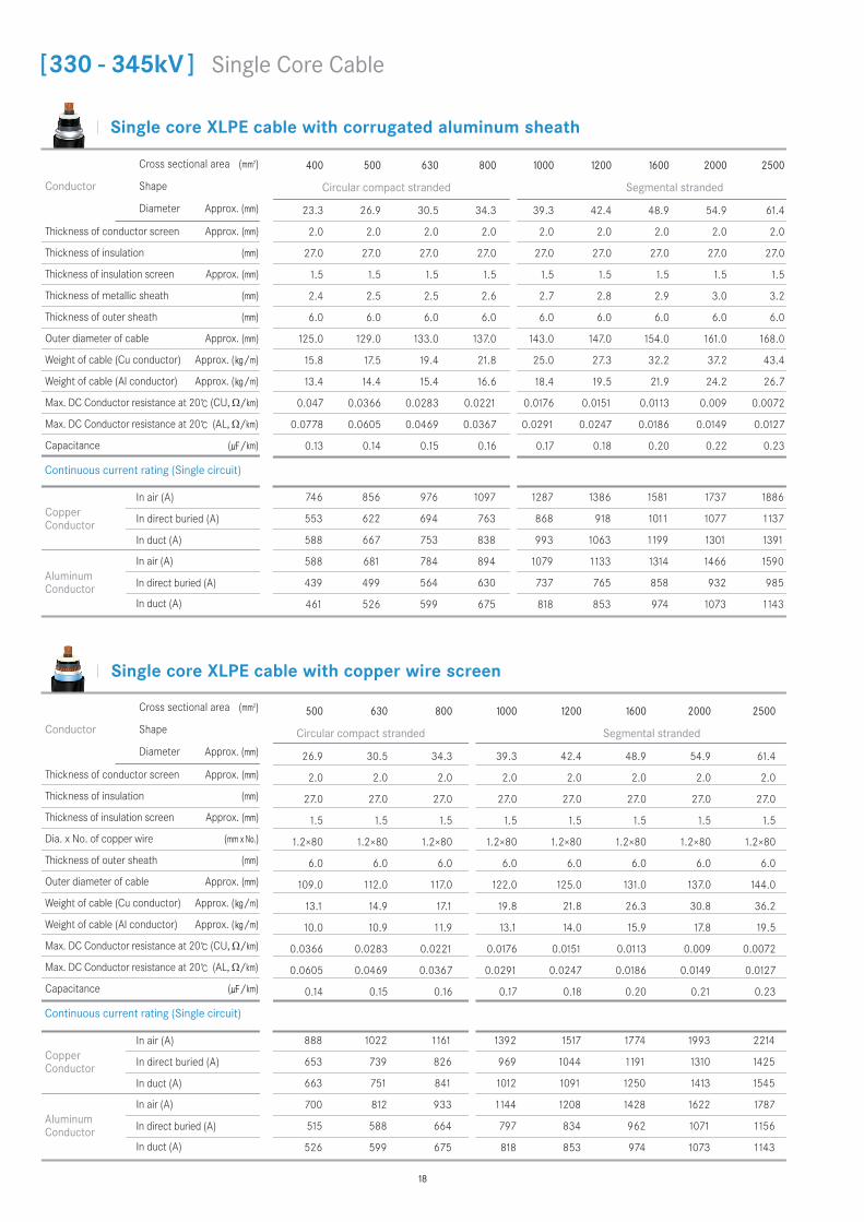
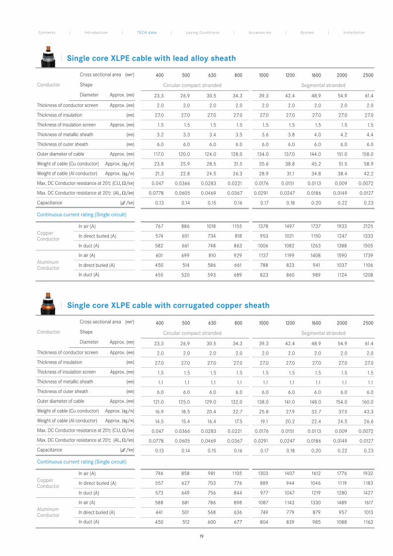
[330 - 345kV ] Single Core Cable
18
Single core XLPE cable with lead alloy sheath
Single core XLPE cable with corrugated copper sheath
Conductor
Cross sectional area (mm2)
Shape
Diameter Approx. (mm)
Thickness of conductor screen Approx. (mm)
Thickness of insulation (mm)
Thickness of insulation screen Approx. (mm)
Thickness of metallic sheath (mm)
Thickness of outer sheath (mm)
Outer diameter of cable Approx. (mm)
Weight of cable (Cu conductor) Approx. (/m)
Weight of cable (Al conductor) Approx. (/m)
Max. DC Conductor resistance at 20 (CU, Ω/km)
Max. DC Conductor resistance at 20 (AL, Ω/km)
Capacitance (/km)
Copper Conductor
In air (A)
In direct buried (A)
In duct (A)
Aluminum Conductor
In air (A)
In direct buried (A)
In duct (A)
746 858 981 1105 1303 1407 1612 1776 1932
557 627 703 776 889 944 1046 1119 1183
573 649 756 844 977 1047 1219 1280 1427
588 681 786 898 1087 1143 1330 1489 1617
441 501 568 636 749 779 879 957 1013
450 512 600 677 804 839 985 1088 1163
400 500 630 800 1000 1200 1600 2000 2500
Circular compact stranded Segmental stranded
23.3 26.9 30.5 34.3 39.3 42.4 48.9 54.9 61.4
2.0 2.0 2.0 2.0 2.0 2.0 2.0 2.0 2.0
27.0 27.0 27.0 27.0 27.0 27.0 27.0 27.0 27.0
1.5 1.5 1.5 1.5 1.5 1.5 1.5 1.5 1.5
1.1 1.1 1.1 1.1 1.1 1.1 1.1 1.1 1.1
6.0 6.0 6.0 6.0 6.0 6.0 6.0 6.0 6.0
121.0 125.0 129.0 132.0 138.0 141.0 148.0 154.0 160.0
16.9 18.5 20.4 22.7 25.8 27.9 32.7 37.5 43.3
14.5 15.4 16.4 17.5 19.1 20.2 22.4 24.5 26.6
0.047 0.0366 0.0283 0.0221 0.0176 0.0151 0.0113 0.009 0.0072
0.0778 0.0605 0.0469 0.0367 0.0291 0.0247 0.0186 0.0149 0.0127
0.13 0.14 0.15 0.16 0.17 0.18 0.20 0.22 0.23
Conductor
Cross sectional area (mm2)
Shape
Diameter Approx. (mm)
Thickness of conductor screen Approx. (mm)
Thickness of insulation (mm)
Thickness of insulation screen Approx. (mm)
Thickness of metallic sheath (mm)
Thickness of outer sheath (mm)
Outer diameter of cable Approx. (mm)
Weight of cable (Cu conductor) Approx. (/m)
Weight of cable (Al conductor) Approx. (/m)
Max. DC Conductor resistance at 20 (CU, Ω/km)
Max. DC Conductor resistance at 20 (AL, Ω/km)
Capacitance (/km)
Copper Conductor
In air (A)
In direct buried (A)
In duct (A)
Aluminum Conductor
In air (A)
In direct buried (A)
In duct (A)
767 886 1018 1155 1378 1497 1737 1933 2125
574 651 734 818 953 1021 1150 1247 1333
582 661 748 863 1006 1082 1263 1388 1505
601 699 810 929 1137 1199 1408 1590 1739
450 514 586 661 788 823 941 1037 1106
455 520 593 689 823 860 989 1124 1208
400 500 630 800 1000 1200 1600 2000 2500
Circular compact stranded Segmental stranded
23.3 26.9 30.5 34.3 39.3 42.4 48.9 54.9 61.4
2.0 2.0 2.0 2.0 2.0 2.0 2.0 2.0 2.0
27.0 27.0 27.0 27.0 27.0 27.0 27.0 27.0 27.0
1.5 1.5 1.5 1.5 1.5 1.5 1.5 1.5 1.5
3.2 3.3 3.4 3.5 3.6 3.8 4.0 4.2 4.4
6.0 6.0 6.0 6.0 6.0 6.0 6.0 6.0 6.0
117.0 120.0 124.0 128.0 134.0 137.0 144.0 151.0 158.0
23.8 25.9 28.5 31.5 35.6 38.8 45.2 51.5 58.9
21.3 22.8 24.5 26.3 28.9 31.1 34.8 38.4 42.2
0.047 0.0366 0.0283 0.0221 0.0176 0.0151 0.0113 0.009 0.0072
0.0778 0.0605 0.0469 0.0367 0.0291 0.0247 0.0186 0.0149 0.0127
0.13 0.14 0.15 0.16 0.17 0.18 0.20 0.22 0.23
Continuous current rating (Single circuit)
Continuous current rating (Single circuit)
Contents | Introduct ion | TECH data | Laying Condit ions | Accessor ies | System | Instal lat ion
19
Single core XLPE cable with copper wire screen
Single core XLPE cable with corrugated aluminum sheath
Conductor
Cross sectional area (mm2)
Shape
Diameter Approx. (mm)
Thickness of conductor screen Approx. (mm)
Thickness of insulation (mm)
Thickness of insulation screen Approx. (mm)
Thickness of metallic sheath (mm)
Thickness of outer sheath (mm)
Outer diameter of cable Approx. (mm)
Weight of cable (Cu conductor) Approx. (/m)
Weight of cable (Al conductor) Approx. (/m)
Max. DC Conductor resistance at 20 (CU, Ω/km)
Max. DC Conductor resistance at 20 (AL, Ω/km)
Capacitance (/km)
Conductor
Cross sectional area (mm2)
Shape
Diameter Approx. (mm)
Thickness of conductor screen Approx. (mm)
Thickness of insulation (mm)
Thickness of insulation screen Approx. (mm)
Dia. x No. of copper wire (mm x No.)
Thickness of outer sheath (mm)
Outer diameter of cable Approx. (mm)
Weight of cable (Cu conductor) Approx. (/m)
Weight of cable (Al conductor) Approx. (/m)
Max. DC Conductor resistance at 20 (CU, Ω/km)
Max. DC Conductor resistance at 20 (AL, Ω/km)
Capacitance (/km)
Copper Conductor
In air (A)
In direct buried (A)
In duct (A)
Aluminum Conductor
In air (A)
In direct buried (A)
In duct (A)
Copper Conductor
In air (A)
In direct buried (A)
In duct (A)
Aluminum Conductor
In air (A)
In direct buried (A)
In duct (A)
630 800 1000 1200 1600 2000 2500
Segmental stranded
30.5 34.3 39.3 42.4 48.9 54.9 61.4
2.0 2.0 2.0 2.0 2.0 2.0 2.0
32.0 30.0 29.0 27.0 27.0 27.0 27.0
1.5 1.5 1.5 1.5 1.5 1.5 1.5
2.7 2.7 2.8 2.8 2.9 3.0 3.2
6.0 6.0 6.0 6.0 6.0 6.0 6.0
144.0 144.0 148.0 147.0 154.0 161.0 168.0
21.8 23.3 26.1 27.3 32.2 37.2 43.4
17.8 18.1 19.4 19.5 21.9 24.2 26.7
0.0283 0.0221 0.0176 0.0151 0.0113 0.009 0.0072
0.0469 0.0367 0.0291 0.0247 0.0186 0.0149 0.0127
0.13 0.15 0.17 0.18 0.20 0.22 0.23
630 800 1000 1200 1600 2000 2500
Segmental stranded
30.5 34.3 39.3 42.4 48.9 54.9 61.4
2.0 2.0 2.0 2.0 2.0 2.0 2.0
32.0 30.0 29.0 27.0 27.0 27.0 27.0
1.5 1.5 1.5 1.5 1.5 1.5 1.5
1.2×80 1.2×80 1.2×80 1.2×80 1.2×80 1.2×80 1.2×80
6.0 6.0 6.0 6.0 6.0 6.0 6.0
123.0 124.0 126.0 126.0 132.0 138.0 145.0
16.7 18.3 20.6 21.9 26.4 30.9 36.3
12.7 13.1 14.0 14.2 16.0 17.9 19.6
0.0283 0.0221 0.0176 0.0151 0.0113 0.009 0.0072
0.0469 0.0367 0.0291 0.0247 0.0186 0.0149 0.0127
0.13 0.15 0.17 0.18 0.20 0.22 0.23
964 1087 1276 1378 1571 1726 1874
687 754 856 905 995 1059 1117
739 824 977 1049 1182 1281 1368
775 886 1070 1126 1306 1457 1580
559 623 727 754 845 916 967
589 664 805 842 960 1056 1124
1004 1142 1365 1489 1735 1941 2149
728 809 942 1008 1142 1249 1350
759 851 993 1070 1221 1379 1502
798 919 1129 1191 1403 1590 1747
580 653 776 811 931 1031 1108
601 680 812 849 978 1113 1199
Continuous current rating (Single circuit)
Continuous current rating (Single circuit)
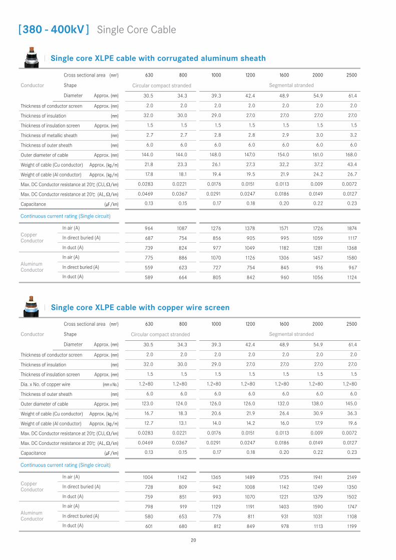
[380 - 400kV ] Single Core Cable
20
Circular compact stranded
Circular compact stranded
Single core XLPE cable with lead alloy sheath
Single core XLPE cable with corrugated copper sheath
Conductor
Cross sectional area (mm2)
Shape
Diameter Approx. (mm)
Thickness of conductor screen Approx. (mm)
Thickness of insulation (mm)
Thickness of insulation screen Approx. (mm)
Thickness of metallic sheath (mm)
Thickness of outer sheath (mm)
Outer diameter of cable Approx. (mm)
Weight of cable (Cu conductor) Approx. (/m)
Weight of cable (Al conductor) Approx. (/m)
Max. DC Conductor resistance at 20 (CU, Ω/km)
Max. DC Conductor resistance at 20 (AL, Ω/km)
Capacitance (/km)
Copper Conductor
In air (A)
In direct buried (A)
In duct (A)
Aluminum Conductor
In air (A)
In direct buried (A)
In duct (A)
Copper Conductor
In air (A)
In direct buried (A)
In duct (A)
Aluminum Conductor
In air (A)
In direct buried (A)
In duct (A)
630 800 1000 1200 1600 2000 2500
Segmental stranded
30.5 34.3 39.3 42.4 48.9 54.9 61.4
2.0 2.0 2.0 2.0 2.0 2.0 2.0
32.0 30.0 29.0 27.0 27.0 27.0 27.0
1.5 1.5 1.5 1.5 1.5 1.5 1.5
3.7 3.7 3.7 3.8 4.0 4.2 4.4
6.0 6.0 6.0 6.0 6.0 6.0 6.0
135.0 135.0 138.0 137.0 144.0 151.0 158.0
32.8 34.4 37.4 38.8 45.2 51.5 58.9
28.8 29.2 30.7 31.1 34.8 38.4 42.2
0.0283 0.0221 0.0176 0.0151 0.0113 0.009 0.0072
0.0469 0.0367 0.0291 0.0247 0.0186 0.0149 0.0127
0.13 0.15 0.17 0.18 0.20 0.22 0.23
630 800 1000 1200 1600 2000 2500
Segmental stranded
30.5 34.3 39.3 42.4 48.9 54.9 61.4
2.0 2.0 2.0 2.0 2.0 2.0 2.0
32.0 30.0 29.0 27.0 27.0 27.0 27.0
1.5 1.5 1.5 1.5 1.5 1.5 1.5
1.2 1.2 1.2 1.2 1.2 1.2 1.2
6.0 6.0 6.0 6.0 6.0 6.0 6.0
140.0 140.0 143.0 142.0 149.0 155.0 161.0
23.1 24.6 27.3 28.4 33.3 38.1 43.9
19.1 19.4 20.6 20.7 22.9 25.1 27.2
0.0283 0.0221 0.0176 0.0151 0.0113 0.009 0.0072
0.0469 0.0367 0.0291 0.0247 0.0186 0.0149 0.0127
0.13 0.15 0.17 0.18 0.20 0.22 0.23
1005 1143 1365 1488 1727 1922 2111
728 810 941 1006 1132 1226 1310
759 850 991 1067 1246 1367 1481
799 920 1126 1192 1400 1581 1728
581 654 779 811 926 1020 1087
601 680 811 848 997 1107 1188
966 1090 1283 1388 1587 1745 1896
692 761 868 919 1015 1083 1142
741 828 957 1027 1194 1298 1391
775 886 1073 1131 1313 1468 1592
561 626 734 761 856 930 982
590 666 789 824 967 1066 1136
Continuous current rating (Single circuit)
Continuous current rating (Single circuit)
Contents | Introduct ion | TECH data | Laying Condit ions | Accessor ies | System | Instal lat ion
21
Circular compact stranded
Circular compact stranded
Correction factors for various laying conditions
Laying conditions
The continuous current rating is calculated in accordance with IEC 60287.
Technical data shown in front pages are calculated based on following laying conditions.
Technical data in front pages shall be multiplied by applicable correction factors in the table below when laying conditions of an actual jobsite are different from the ones given above.
* Technical data for these cables is available upon request.
Continuous current ratings and Correction factors
Other Cables
1) Ground temperature : 30() 2) Ambient temperature : 40() 3) Soil thermal resistivity : 1.2K.m/W
4) Depth of laying : 1.5m 5) Installation formation : Trefoil formation 6) Max. conductor temperature : 90()
7) Frequency : 50Hz 8) Load factor : 100% 9) Sheath ground : Cross bonding
Depth of laying (m) 0.5 0.8 1.0 1.2 1.5 2.0 2.5
Correction factor 1.10 1.16 1.07 1.00 0.92 0.82 0.74
Ambient temperature () 25 30 35 40 45 50 55
Correction factor 1.16 1.11 1.06 1.00 0.94 0.88 0.82
Ground temperature () 20 25 30 35 40 45 50
Correction factor 1.08 1.04 1.00 0.96 0.91 0.87 0.82
Thermal resistivity of soil (K.m/W) 0.8 1.0 1.2 1.5 2.0 2.5 3.0
Correction factor 1.16 1.07 1.00 0.92 0.82 0.74 0.69
FOC embedded type (for DTS or DRS)
Wire shield + Lead alloy + Aluminum armor type
Smooth welded metal sheath type
22
Rated voltage [kV]
ConductorSize [mm2]
Approx.Dimension [mm]
Normal Joint Insulation Joint
Length (A) Approx.Max Outer Dia.ø Length (A) Approx.Max Outer Dia.ø
60~69kV
240~2500
1700 260 1700 270
110~138kV 2000 280 2000 310
150~161kV 2000 310 2000 330
220~230kV 2200 340 2200 360
330~345kV 2200 370 2200 380
380~400kV 2200 390 2200 400
Pre Fabricated Joint
Rating & Dimension
TECH DATA FOR CABLE ACCESSORIES
Contents | Introduct ion | TECH data | Laying Condit ions | Accessor ies | System | Instal lat ion
Normal Joint (NJ)
Insulation Joint (IJ)
Stress Relief Cone
Stress Relief Cone
Epoxy Unit
Epoxy Unit
Compressing Device
Compressing Device
Conductor Sleeve
Conductor SleeveInsulating Barrier
Protection Box
Protection Box
A
A
23
Rated voltage [kV]
ConductorSize [mm2]
Approx.Dimension [mm]
Normal Joint Insulation Joint
Length (A) Approx.Max Outer Dia.ø Length (A) Approx.Max Outer Dia.ø
60~69kV
240~2500
1600 260 1600 260
110~138kV 1800 280 1800 280
150~161kV 2000 310 2000 310
220~230kV 2000 340 2000 340
330~345kV 2200 420 2200 420
380~400kV 2200 420 2200 420
Rating & Dimension
Pre Molded Joint (PMJ)
Insulation Joint (IJ)
Conductor Sleeve & Shield Ring Rubber UnitProtection Box
Insulating Barrier
Normal Joint (NJ)
Conductor Sleeve & Shield Ring Rubber UnitProtection Box
TECH DATA FOR CABLE ACCESSORIES
A
A
24
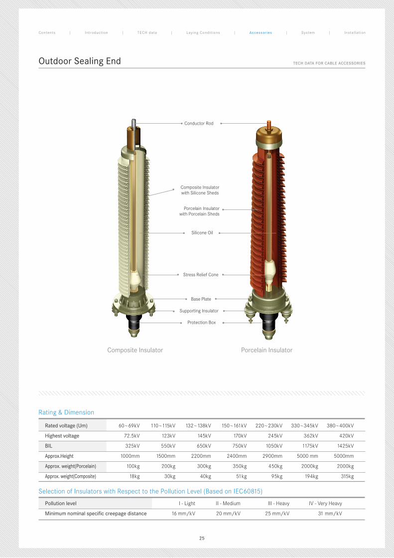
Outdoor Sealing End
Selection of Insulators with Respect to the Pollution Level (Based on IEC60815)
Rated voltage (Um) 60~69kV 110~115kV 132~138kV 150~161kV 220~230kV 330~345kV 380~400kV
Highest voltage 72.5kV 123kV 145kV 170kV 245kV 362kV 420kV
BIL 325kV 550kV 650kV 750kV 1050kV 1175kV 1425kV
Approx.Height 1000mm 1500mm 2200mm 2400mm 2900mm 5000 mm 5000mm
Approx. weight(Porcelain) 100kg 200kg 300kg 350kg 450kg 2000kg 2000kg
Approx. weight(Composite) 18kg 30kg 40kg 51kg 95kg 194kg 315kg
Pollution level I - Light II - Medium III - Heavy IV - Very Heavy
Minimum nominal specific creepage distance 16 mm/kV 20 mm/kV 25 mm/kV 31 mm/kV
Rating & Dimension
Conductor Rod
Composite Insulatorwith Silicone Sheds
Porcelain Insulatorwith Porcelain Sheds
Silicone Oil
Stress Relief Cone
Base Plate
Supporting Insulator
Protection Box
Composite Insulator Porcelain Insulator
TECH DATA FOR CABLE ACCESSORIES
Contents | Introduct ion | TECH data | Laying Condit ions | Accessor ies | System | Instal lat ion
25
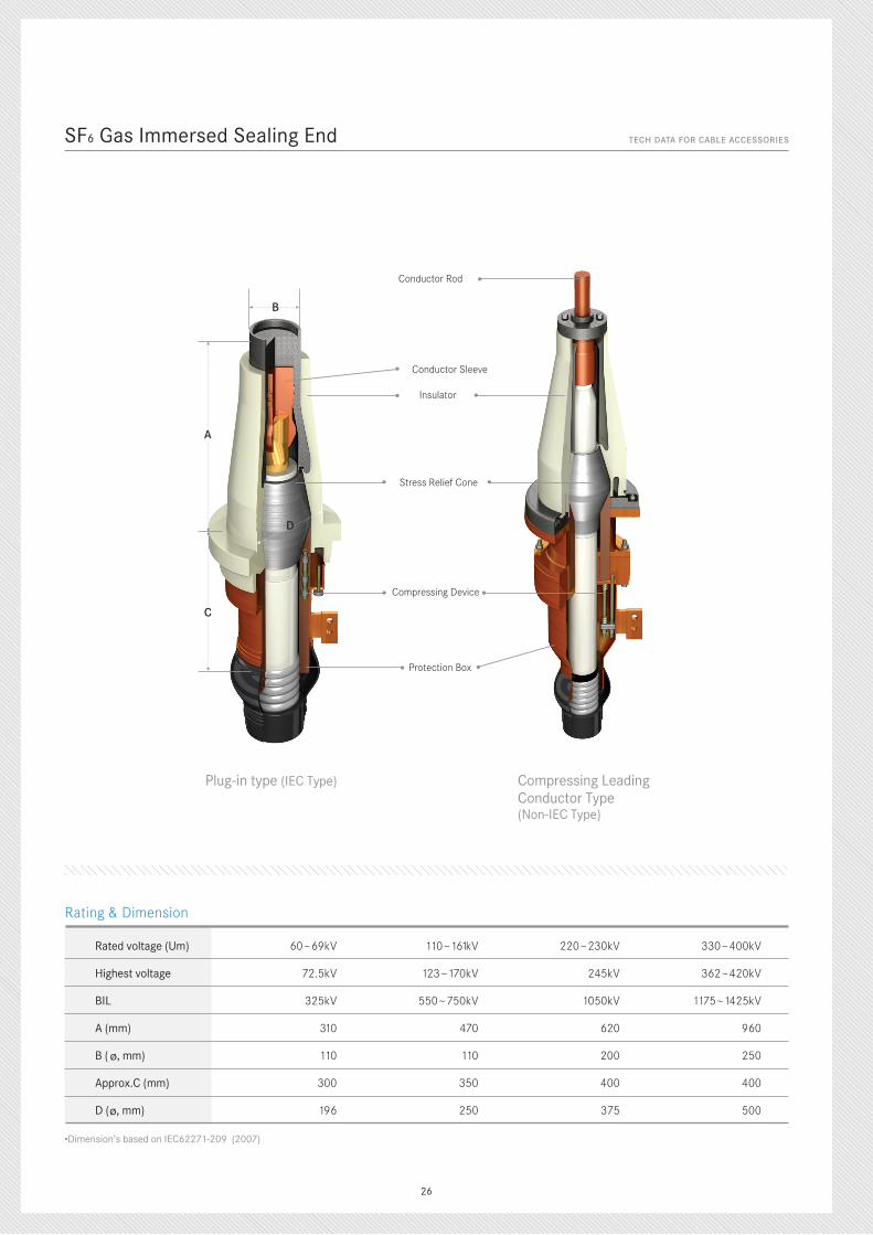
SF6 Gas Immersed Sealing End
•Dimension’s based on IEC62271-209 (2007)
Rated voltage (Um) 60~69kV 110~161kV 220~230kV 330~400kV
Highest voltage 72.5kV 123~170kV 245kV 362~420kV
BIL 325kV 550~750kV 1050kV 1175~1425kV
A (mm) 310 470 620 960
B (ø, mm) 110 110 200 250
Approx.C (mm) 300 350 400 400
D (ø, mm) 196 250 375 500
Rating & Dimension
Conductor Rod
Stress Relief Cone
Insulator
Conductor Sleeve
Compressing Device
Protection Box
Plug-in type (IEC Type) Compressing LeadingConductor Type(Non-IEC Type)
TECH DATA FOR CABLE ACCESSORIES
D
B
C
A
26
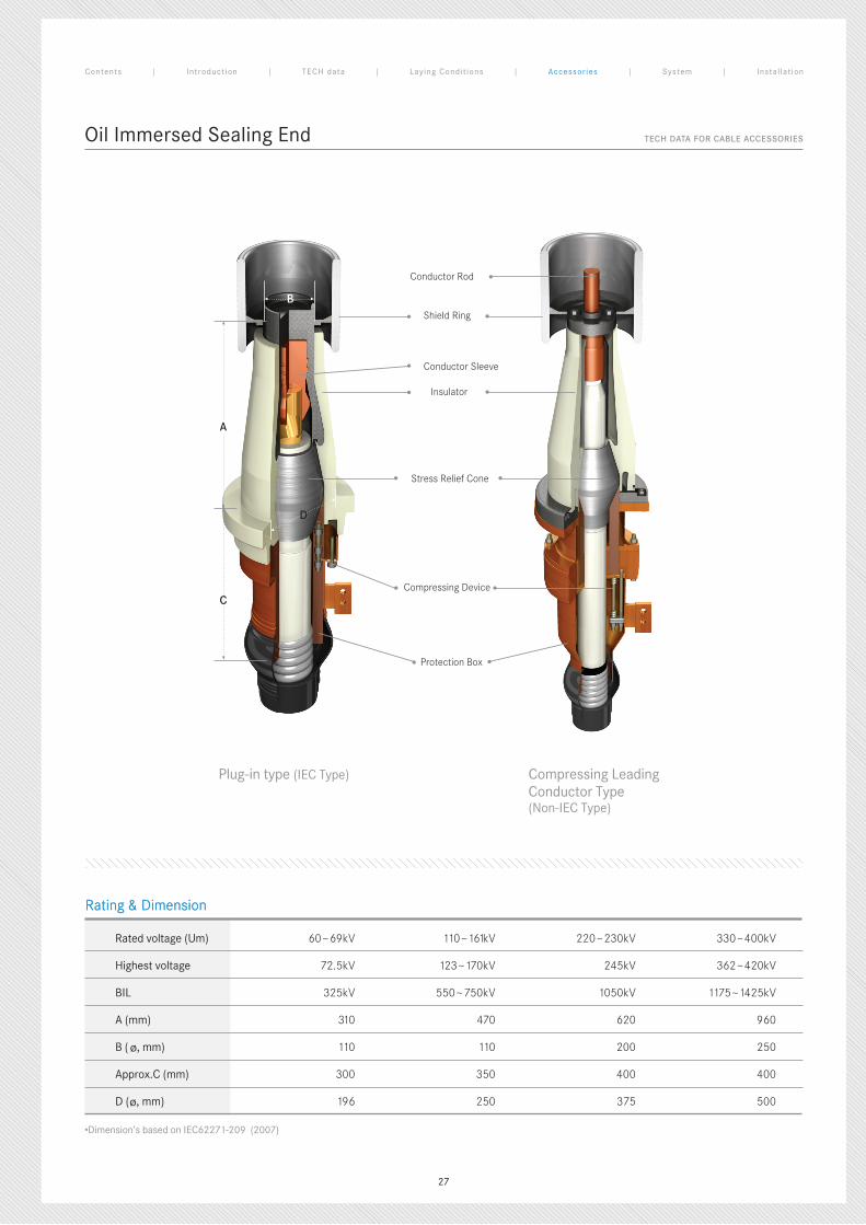
Oil Immersed Sealing End
•Dimension’s based on IEC62271-209 (2007)
Rated voltage (Um) 60~69kV 110~161kV 220~230kV 330~400kV
Highest voltage 72.5kV 123~170kV 245kV 362~420kV
BIL 325kV 550~750kV 1050kV 1175~1425kV
A (mm) 310 470 620 960
B (ø, mm) 110 110 200 250
Approx.C (mm) 300 350 400 400
D (ø, mm) 196 250 375 500
Rating & Dimension
Conductor Rod
Stress Relief Cone
Shield Ring
Insulator
Conductor Sleeve
Compressing Device
Protection Box
Plug-in type (IEC Type) Compressing LeadingConductor Type(Non-IEC Type)
TECH DATA FOR CABLE ACCESSORIES
Rating & Dimension
Contents | Introduct ion | TECH data | Laying Condit ions | Accessor ies | System | Instal lat ion
C
D
B
A
27
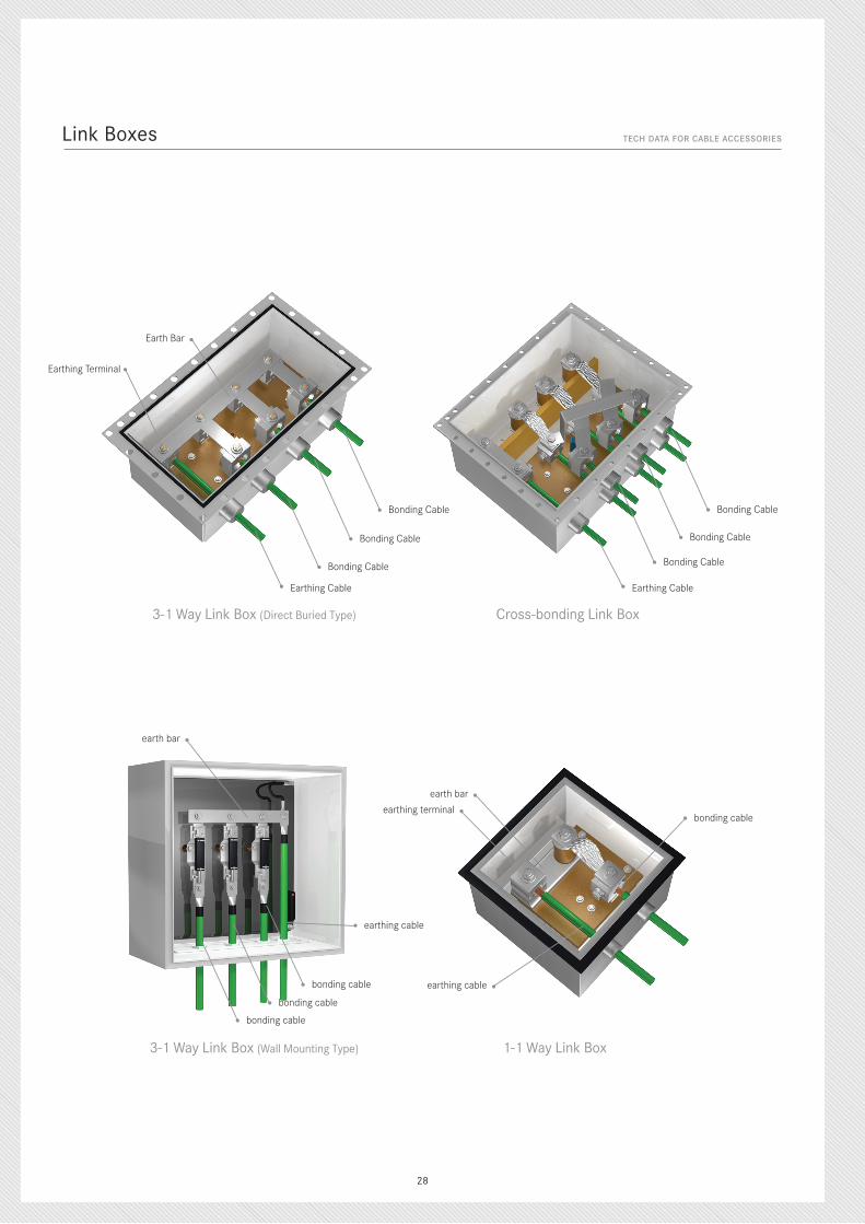
Link Boxes
3-1 Way Link Box (Direct Buried Type)
3-1 Way Link Box (Wall Mounting Type)
Cross-bonding Link Box
1-1 Way Link Box
Bonding Cable
Bonding Cable
Earthing Cable Earthing Cable
Bonding Cable
TECH DATA FOR CABLE ACCESSORIES
Earth Bar
earth bar
earth bar
earthing terminal
earthing cable
Bonding Cable
Bonding Cable
Bonding Cable
bonding cable
bonding cable
bonding cable
bonding cable
earthing cable
Earthing Terminal
28
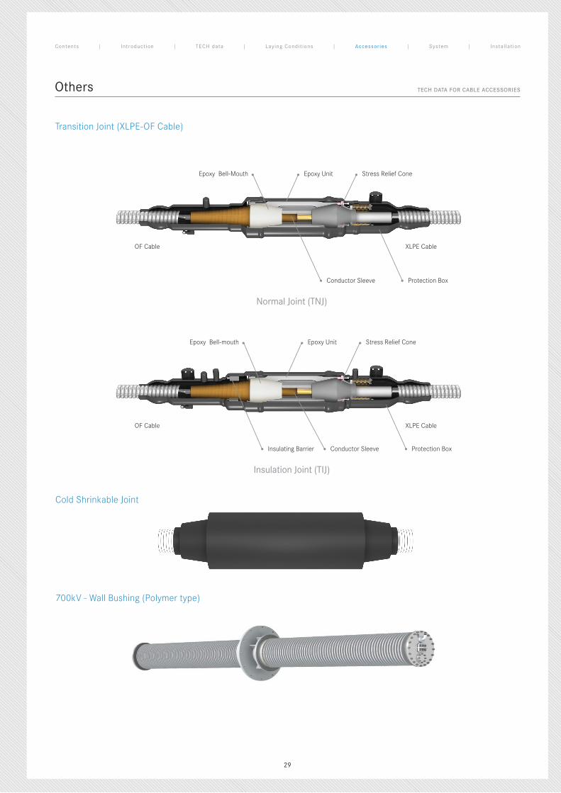
Others
Normal Joint (TNJ)
Epoxy UnitEpoxy Bell-Mouth Stress Relief Cone
Conductor Sleeve
OF Cable
OF Cable
XLPE Cable
XLPE Cable
Protection Box
Insulation Joint (TIJ)
Epoxy UnitEpoxy Bell-mouth Stress Relief Cone
Conductor SleeveInsulating Barrier Protection Box
TECH DATA FOR CABLE ACCESSORIES
Transition Joint (XLPE-OF Cable)
Cold Shrinkable Joint
700kV - Wall Bushing (Polymer type)
Contents | Introduct ion | TECH data | Laying Condit ions | Accessor ies | System | Instal lat ion
29
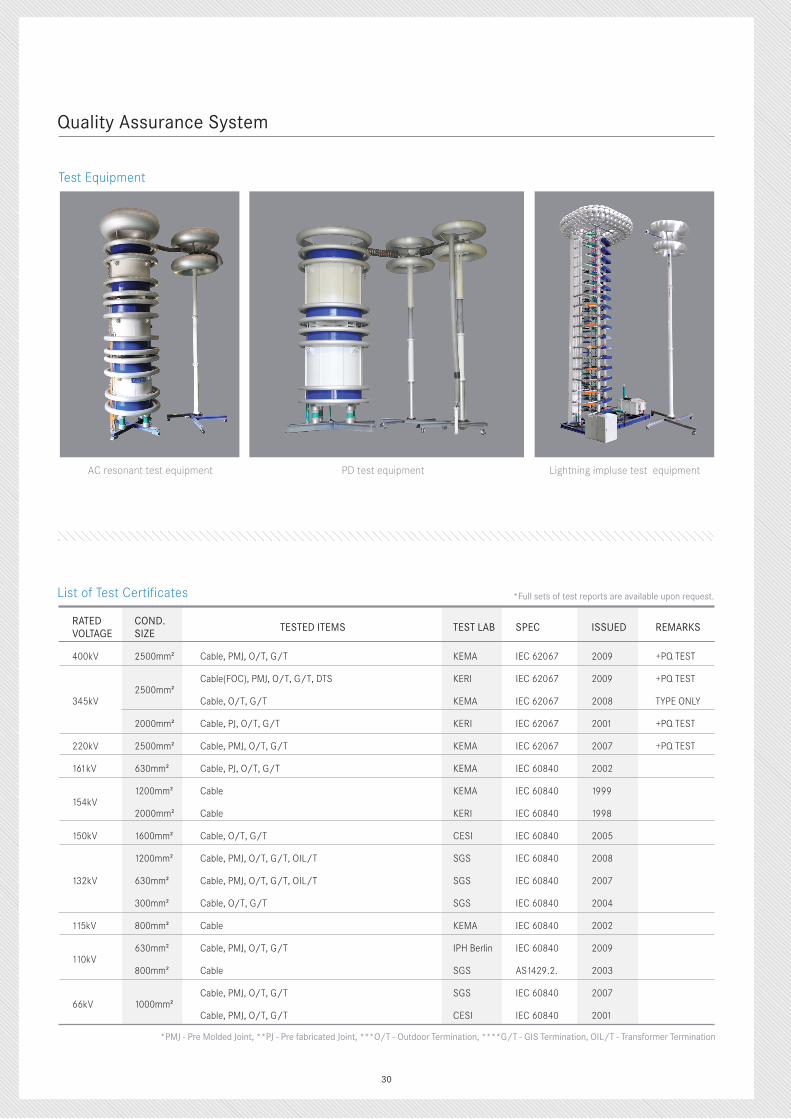
Quality Assurance System
List of Test Certificates
RATED VOLTAGE
COND. SIZE
TESTED ITEMS TEST LAB SPEC ISSUED REMARKS
400kV 2500mm2 Cable, PMJ, O/T, G/T KEMA IEC 62067 2009 +PQ TEST
345kV2500mm2
Cable(FOC), PMJ, O/T, G/T, DTS KERI IEC 62067 2009 +PQ TEST
Cable, O/T, G/T KEMA IEC 62067 2008 TYPE ONLY
2000mm2 Cable, PJ, O/T, G/T KERI IEC 62067 2001 +PQ TEST
220kV 2500mm2 Cable, PMJ, O/T, G/T KEMA IEC 62067 2007 +PQ TEST
161kV 630mm2 Cable, PJ, O/T, G/T KEMA IEC 60840 2002
154kV1200mm2 Cable KEMA IEC 60840 1999
2000mm2 Cable KERI IEC 60840 1998
150kV 1600mm2 Cable, O/T, G/T CESI IEC 60840 2005
132kV
1200mm2 Cable, PMJ, O/T, G/T, OIL/T SGS IEC 60840 2008
630mm2 Cable, PMJ, O/T, G/T, OIL/T SGS IEC 60840 2007
300mm2 Cable, O/T, G/T SGS IEC 60840 2004
115kV 800mm2 Cable KEMA IEC 60840 2002
110kV630mm2 Cable, PMJ, O/T, G/T IPH Berlin IEC 60840 2009
800mm2 Cable SGS AS1429.2. 2003
66kV 1000mm2Cable, PMJ, O/T, G/T SGS IEC 60840 2007
Cable, PMJ, O/T, G/T CESI IEC 60840 2001
Test Equipment
AC resonant test equipment Lightning impluse test equipmentPD test equipment
*PMJ - Pre Molded Joint, **PJ - Pre fabricated Joint, ***O/T - Outdoor Termination, ****G/T - GIS Termination, OIL/T - Transformer Termination
*Full sets of test reports are available upon request.
30
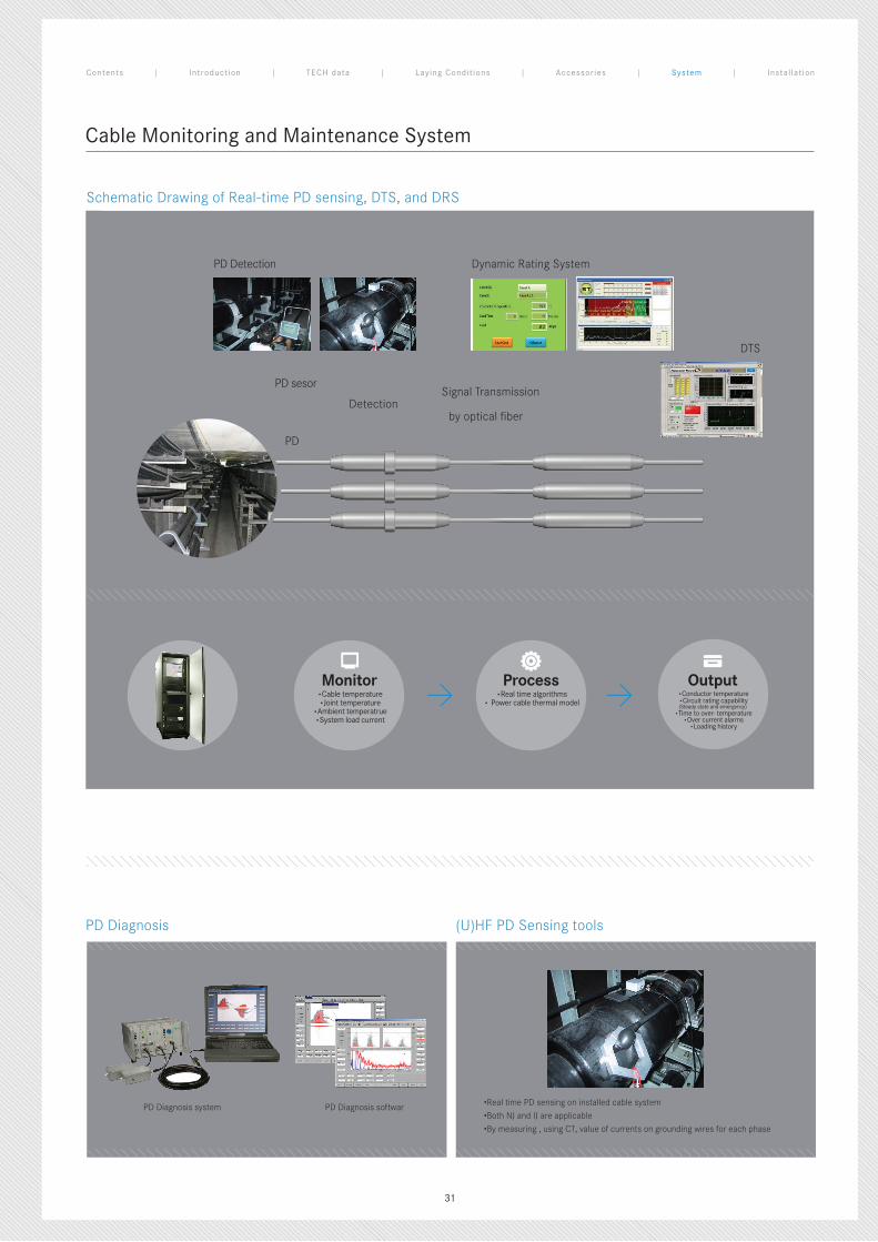
Cable Monitoring and Maintenance System
PD Diagnosis (U)HF PD Sensing tools
PD Diagnosis system PD Diagnosis softwar •Real time PD sensing on installed cable system
•Both NJ and IJ are applicable
•By measuring , using CT, value of currents on grounding wires for each phase
Schematic Drawing of Real-time PD sensing, DTS, and DRS
Monitor•Cable temperature•Joint temperature
•Ambient temperatrue•System load current
Process•Real time algorithms
• Power cable thermal model
Output•Conductor temperature•Circuit rating capability(Steady state and emergency)
•Time to over- temperature•Over current alarms
•Loading history
> >
Dynamic Rating System
Signal Transmission
by optical fiber
DTS
PD Detection
Detection
PD sesor
PD
Contents | Introduct ion | TECH data | Laying Condit ions | Accessor ies | System | Instal lat ion
31
Cable Installation & System Design
1. Cable Laying Method
Direct Buried In Underground Duct In Air (Tunnel)
Advantage- Low cost for installation - Good heat dissipation
- Convenience in expanding / removing - No chance of external damage
- Convenience in installing multi-line - Good heat dissipation
Disadvantage- Inconvenience of maintenance - Exposed to external damage
- High cost for installation - Limited permissible current for multi-line
- Excessive installation cost
2. Maximum cable pulling tension
The cable pulling tension is calculated from the following equation and should be within allowable tensile strength of conductor.
1) Using a pulling eye to conductor
- Copper : 7kg/mm2 of conductor
- Aluminum : 4kg/mm2 of conductor
2) Using a stocking grip
T = 0.357D2 [kg]
D : Cable overall diameter [mm]
4. Maximum sidewall pressure
P = T / R
P : Maximum sidewall pressure [kg/m]] T : Maximum pulling tension [kg] R : Minimum bending radius [m]
Wire screen type Lead sheath type Corrugated sheath type Armoured cable
Min. Bending Radius 20D 20D 18D 15D
3. Minimum Bending Radius
*Minimum Bending Radius
The data on the table below shall be considered in order to install cables without any damages on their electrical and physical properties.
32
Cable Installation & System Design
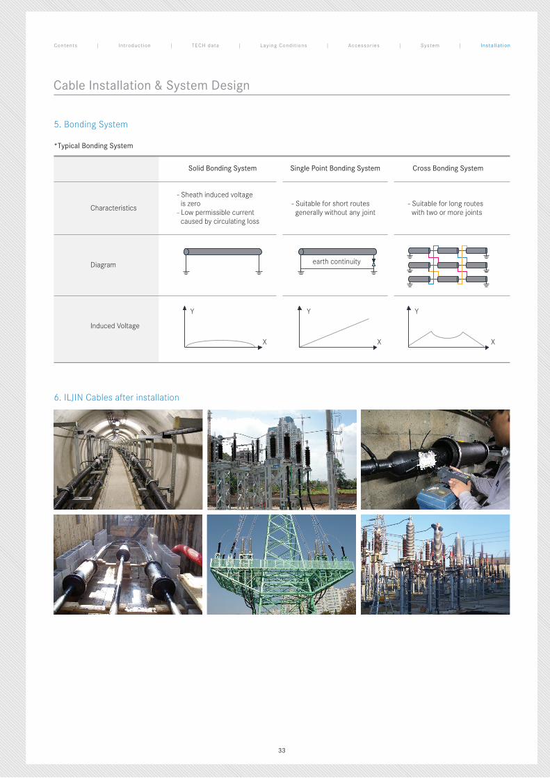
6. ILJIN Cables after installation
Contents | Introduct ion | TECH data | Laying Condit ions | Accessor ies | System | Instal lat ion
*Typical Bonding System
Solid Bonding System Single Point Bonding System Cross Bonding System
Characteristics
- Sheath induced voltage is zero - Low permissible current caused by circulating loss
- Suitable for short routes generally without any joint
- Suitable for long routes with two or more joints
Diagram
Induced Voltage
5. Bonding System
earth continuity
Y Y Y
XXX
33
WWW.ILJINELECTRIC.CO.KR
PLANT112-83, Annyeong-dong, Hwaseong-si, Gyeonggi-do, Korea Tel.+82-31-220-0900 Fax.+82-31-220-0909
SEOUL OFFICE12F ILJIN Building, 50-1 Dohwa-dong, Mapo-gu, Seoul, Korea Tel.+82-2-707-9711 Fax.+82-2-707-9685
ILJIN ELECTRIC CO., LTD. CABLE DIVISION