eie325: telecommunication technologiesmaciej j. ogorza ł ek, polyu, eie telecommunication...
Post on 21-Dec-2015
233 views
TRANSCRIPT
EIE325: Telecommunication Technologies Maciej J. Ogorzałek, PolyU, EIE
Telecommunication Technologies
Week 11
Circuit SwitchingPacket Switching
EIE325: Telecommunication Technologies Maciej J. Ogorzałek, PolyU, EIE
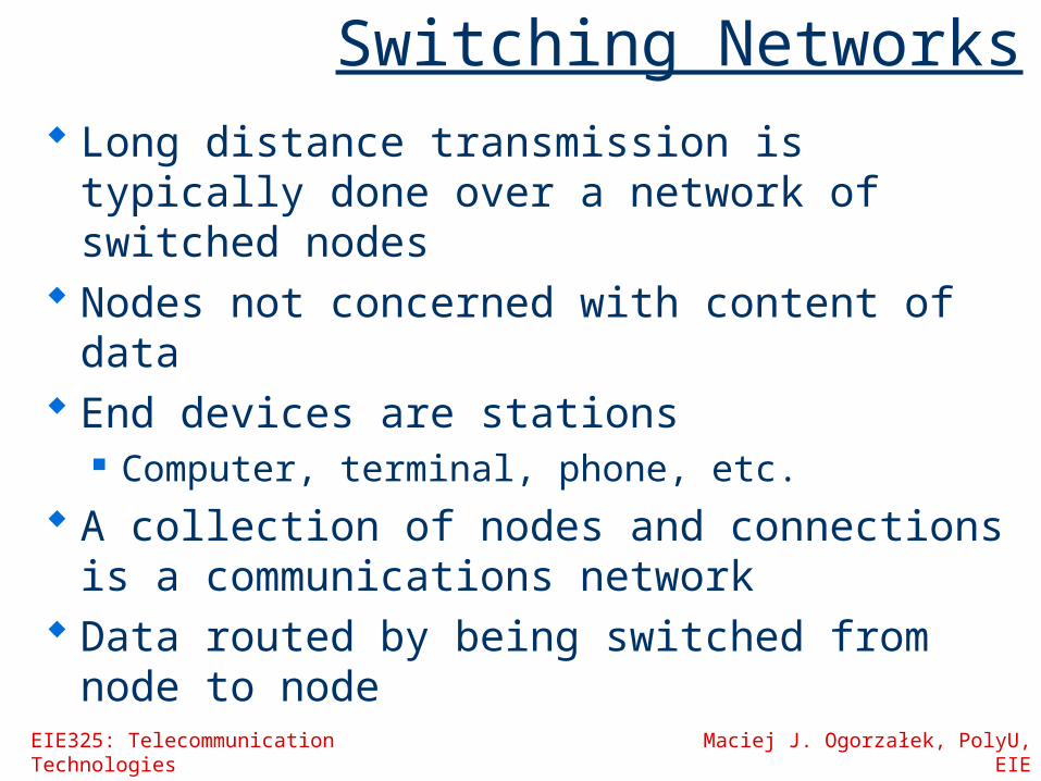
Switching Networks Long distance transmission is typically
done over a network of switched nodes Nodes not concerned with content of
data End devices are stations
Computer, terminal, phone, etc. A collection of nodes and connections
is a communications network Data routed by being switched from
node to node

EIE325: Telecommunication Technologies Maciej J. Ogorzałek, PolyU, EIE
Nodes
Nodes may connect to other nodes only, or to stations and other nodes
Node to node links usually multiplexed Network is usually partially connected
Some redundant connections are desirable for reliability
Transmission of switched nodes may be either… Circuit switching Packet switching

Simple Switched Network

EIE325: Telecommunication Technologies Maciej J. Ogorzałek, PolyU, EIE
Circuit Switching Dedicated communication path
between two stations Three phases
Establish Transfer Disconnect
Must have switching capacity and channel capacity to establish connection
Must have “intelligence” to work out routing
EIE325: Telecommunication Technologies Maciej J. Ogorzałek, PolyU, EIE
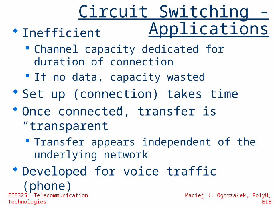
Circuit Switching - Applications Inefficient
Channel capacity dedicated for duration of connection
If no data, capacity wasted Set up (connection) takes time Once connected, transfer is
“transparent” Transfer appears independent of the
underlying network Developed for voice traffic (phone)

EIE325: Telecommunication Technologies Maciej J. Ogorzałek, PolyU, EIE
Public Circuit Switched Network
Consists of several (hierarchical) levels of switching between end nodes.

EIE325: Telecommunication Technologies Maciej J. Ogorzałek, PolyU, EIE
Telecomms Components
Subscriber Devices attached to
network
Local Loop Subscriber loop Connection to
network
Exchange Switching centers End office - supports
subscribers
Trunks Branches between
exchanges Multiplexed

Circuit Switch Elements
Generic switch elements: duplex lines to
devices network interface digital switching control

EIE325: Telecommunication Technologies Maciej J. Ogorzałek, PolyU, EIE
Circuit Switching Concepts Digital Switch
Provide transparent signal path between devices
Network Interface Control Unit
Establish connectionsGenerally on demandHandle and acknowledge requestsDetermine if destination is freeconstruct path
Maintain connection Disconnect
EIE325: Telecommunication Technologies Maciej J. Ogorzałek, PolyU, EIE
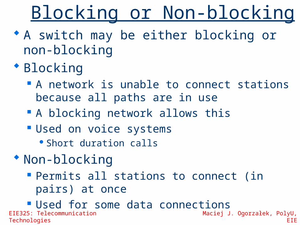
Blocking or Non-blocking A switch may be either blocking or non-
blocking Blocking
A network is unable to connect stations because all paths are in use
A blocking network allows this Used on voice systems
Short duration calls
Non-blocking Permits all stations to connect (in pairs) at
once Used for some data connections

EIE325: Telecommunication Technologies Maciej J. Ogorzałek, PolyU, EIE
Space Division Switching
Developed for analog environment Separate physical paths Crossbar switch
Number of crosspoints grows as square of number of stations
Loss of crosspoint prevents connection Inefficient use of crosspoints
All stations connected, only a few crosspoints in use
Non-blocking

EIE325: Telecommunication Technologies Maciej J. Ogorzałek, PolyU, EIE
Crossbar Matrix
Caller
Receiver
Appropriate switch is activated to connect call
EIE325: Telecommunication Technologies Maciej J. Ogorzałek, PolyU, EIE
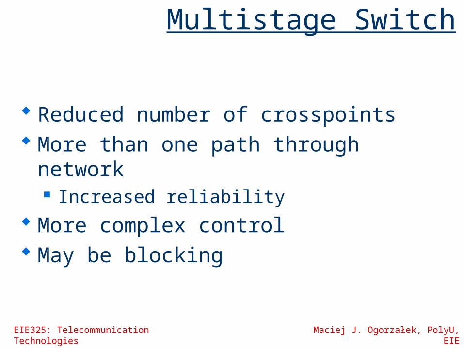
Multistage Switch
Reduced number of crosspoints More than one path through network
Increased reliability More complex control May be blocking
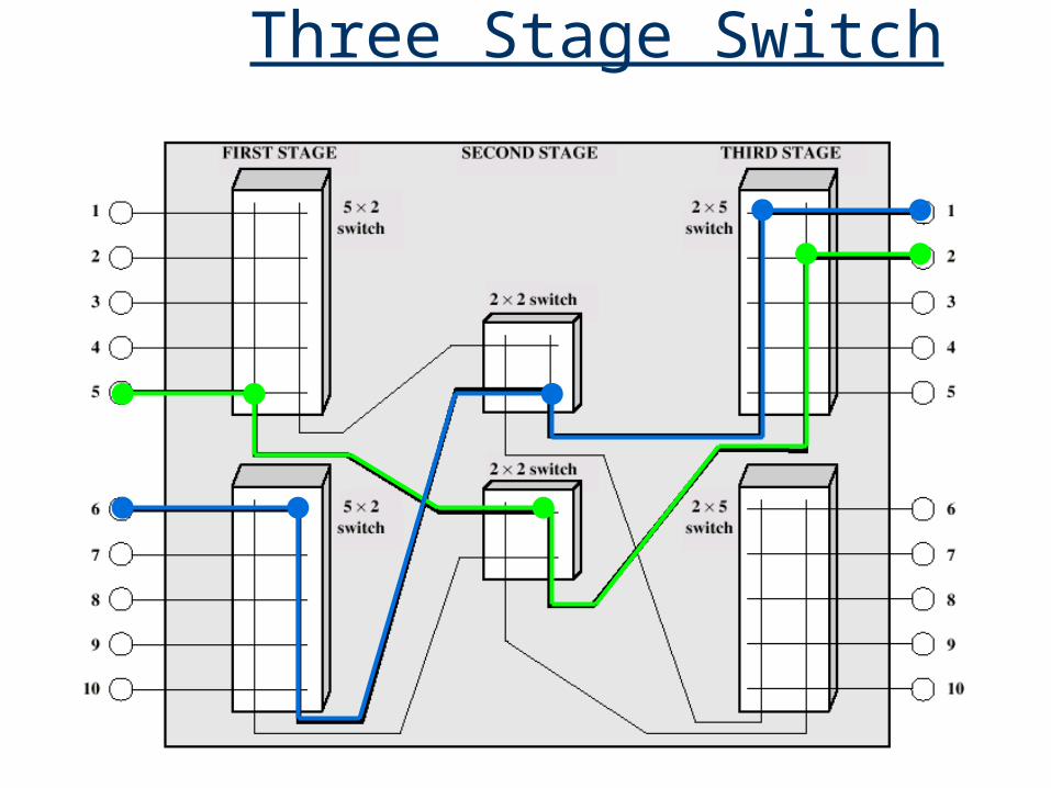
Three Stage Switch

EIE325: Telecommunication Technologies Maciej J. Ogorzałek, PolyU, EIE
How many connections are required for the previous three stage switch compared to the crossbar matrix? How many calls can simultaneously be supported in each?

EIE325: Telecommunication Technologies Maciej J. Ogorzałek, PolyU, EIE
Time Division Switching Partition low speed bit stream into
pieces that share higher speed stream e.g. TDM bus switching
based on synchronous time division multiplexing
Each station connects through controlled gates to high speed bus
Time slot allows small amount of data onto bus
Another line’s gate is enabled for output at the same time
EIE325: Telecommunication Technologies Maciej J. Ogorzałek, PolyU, EIE
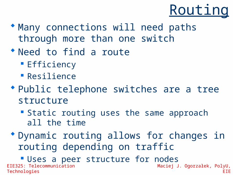
Routing Many connections will need paths through
more than one switch Need to find a route
Efficiency Resilience
Public telephone switches are a tree structure Static routing uses the same approach all the
time Dynamic routing allows for changes in
routing depending on traffic Uses a peer structure for nodes
EIE325: Telecommunication Technologies Maciej J. Ogorzałek, PolyU, EIE
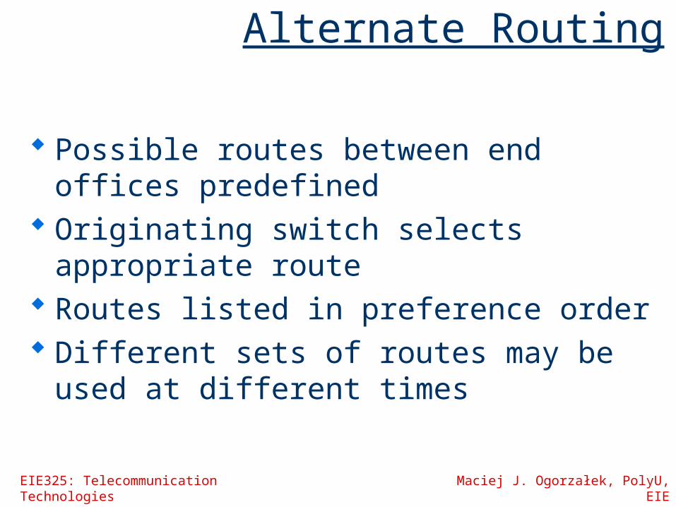
Alternate Routing
Possible routes between end offices predefined
Originating switch selects appropriate route
Routes listed in preference order Different sets of routes may be used at
different times

EIE325: Telecommunication Technologies Maciej J. Ogorzałek, PolyU, EIE
Control Signaling Functions
Audible communication with subscriber
Transmission of dialled number
Call cannot be completed indication
Call ended indication
Signal to ring phone Billing info Equipment and
trunk status info Diagnostic info Control of specialist
equipment

EIE325: Telecommunication Technologies Maciej J. Ogorzałek, PolyU, EIE
Switch to Switch Signaling Subscribers connected to different
switches Originating switch seizes inter-switch
trunk Send off hook signal on trunk,
requesting digit register at target switch (for address)
Terminating switch sends off hook followed by on hook (wink) to show register ready
Originating switch sends address

EIE325: Telecommunication Technologies Maciej J. Ogorzałek, PolyU, EIE
Location of Signalling
Subscriber to network Depends on subscriber device and switch
Within network Management of subscriber calls and
network More complex

EIE325: Telecommunication Technologies Maciej J. Ogorzałek, PolyU, EIE
In Channel Signalling
Use same channel for signalling and call Requires no additional transmission facilities
In-band Uses same frequencies as voice signal Can go anywhere a voice signal can Impossible to set up a call on a faulty speech path
Out of band Voice signals do not use full 4kHz bandwidth Narrow signal band within 4kHz used for control Can be sent whether or not voice signals are
present Need extra electronics Slower signal rate (narrow bandwidth)
EIE325: Telecommunication Technologies Maciej J. Ogorzałek, PolyU, EIE
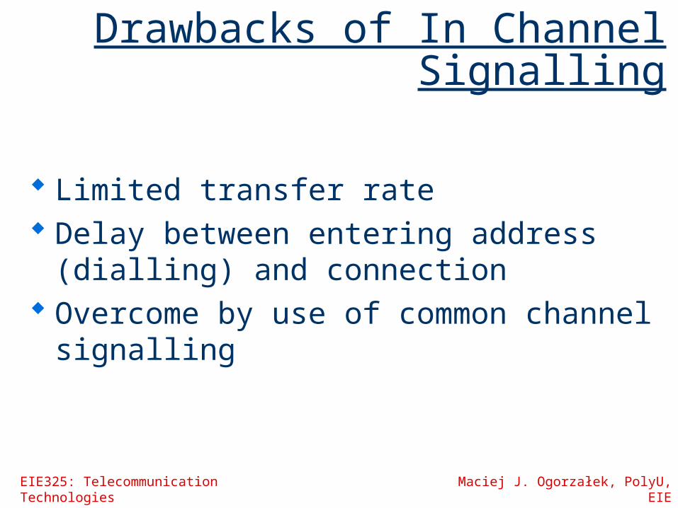
Drawbacks of In Channel Signalling
Limited transfer rate Delay between entering address
(dialling) and connection Overcome by use of common channel
signalling

EIE325: Telecommunication Technologies Maciej J. Ogorzałek, PolyU, EIE
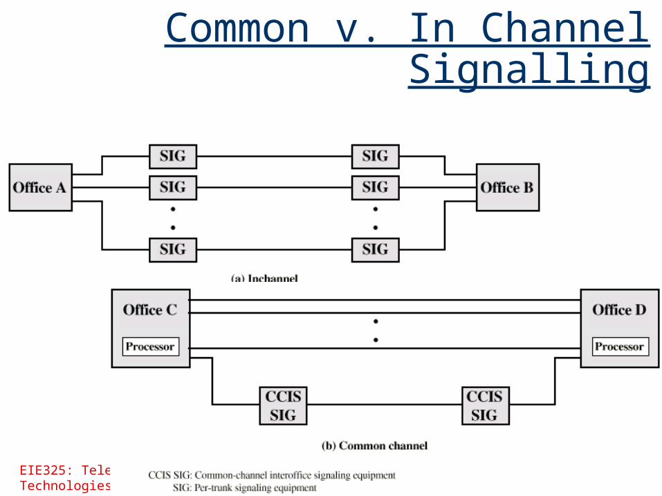
Common Channel Signalling Control signals carried over paths
independent of voice channel One control signal channel can carry signals
for a number of subscriber channels Common control channel for these subscriber
lines Associated Mode
Common channel closely tracks interswitch trunks
Disassociated Mode Additional nodes (signal transfer points) Effectively two separate networks
EIE325: Telecommunication Technologies Maciej J. Ogorzałek, PolyU, EIE
Common v. In Channel Signalling

Signalling Modes

EIE325: Telecommunication Technologies Maciej J. Ogorzałek, PolyU, EIE
Signalling System Number 7
SS7 Common channel signalling scheme ISDN Optimized for 64k digital channel network Call control, remote control, management
and maintenance Reliable means of transfer of info in
sequence Will operate over analog and below 64k Point to point terrestrial and satellite links
EIE325: Telecommunication Technologies Maciej J. Ogorzałek, PolyU, EIE
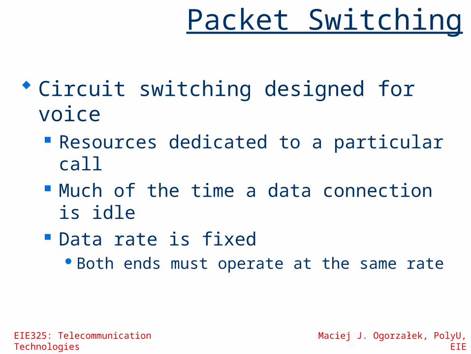
Packet Switching
Circuit switching designed for voice Resources dedicated to a particular call Much of the time a data connection is idle Data rate is fixed
Both ends must operate at the same rate
EIE325: Telecommunication Technologies Maciej J. Ogorzałek, PolyU, EIE
EIE325: Telecommunication Technologies Maciej J. Ogorzałek, PolyU, EIE
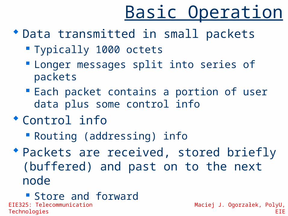
Basic Operation Data transmitted in small packets
Typically 1000 octets Longer messages split into series of
packets Each packet contains a portion of user data
plus some control info Control info
Routing (addressing) info Packets are received, stored briefly
(buffered) and past on to the next node Store and forward

EIE325: Telecommunication Technologies Maciej J. Ogorzałek, PolyU, EIE
Advantages Line efficiency
Single node to node link can be shared by many packets over time
Packets queued and transmitted as fast as possible
Data rate conversion Each station connects to the local node at its own
speed Nodes buffer data if required to equalise rates
Packets are accepted even when network is busy Delivery may slow down
Priorities can be used

EIE325: Telecommunication Technologies Maciej J. Ogorzałek, PolyU, EIE
Switching Technique
Station breaks long message into packets
Packets sent one at a time to the network
Packets handled in two ways Datagram Virtual circuit

EIE325: Telecommunication Technologies Maciej J. Ogorzałek, PolyU, EIE
Datagram
Each packet treated independently Packets can take any practical route Packets may arrive out of order Packets may go missing Up to receiver to re-order packets and
recover from missing packets

EIE325: Telecommunication Technologies Maciej J. Ogorzałek, PolyU, EIE
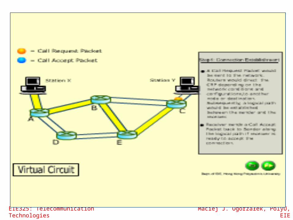
Virtual Circuit
Preplanned route established before any packets sent
Call request and call accept packets establish connection (handshake)
Each packet contains a virtual circuit identifier instead of destination address
No routing decisions required for each packet Clear request to drop circuit Not a dedicated path

EIE325: Telecommunication Technologies Maciej J. Ogorzałek, PolyU, EIE
Virtual Circuit vs Datagram Virtual circuits
Network can provide sequencing and error control Packets are forwarded more quickly
No routing decisions to make Less reliable
Loss of a node looses all circuits through that node
Datagram No call setup phase
Better if few packets More flexible
Routing can be used to avoid congested parts of the network

Packet Size
Data to be set in one large packet, with a small fixed header. First from
X (source) to a
Then from a to b
And finally, from b to Y (destination) But, with more (smaller)
packets the data can be forwarded sooner, and this reduces transmission time.
If the individual packets are too small, then the header size
becomes significant, and the transmission takes longer.

EIE325: Telecommunication Technologies Maciej J. Ogorzałek, PolyU, EIE
Referring to the previous diagram, what is the optimum packet size to transmit 20kB of data over 2 intermediary nodes with 32 bits of header information?

EIE325: Telecommunication Technologies Maciej J. Ogorzałek, PolyU, EIE
Circuit vs Packet Switching
Performance Propagation delay Transmission time Node delay
EIE325: Telecommunication Technologies Maciej J. Ogorzałek, PolyU, EIE
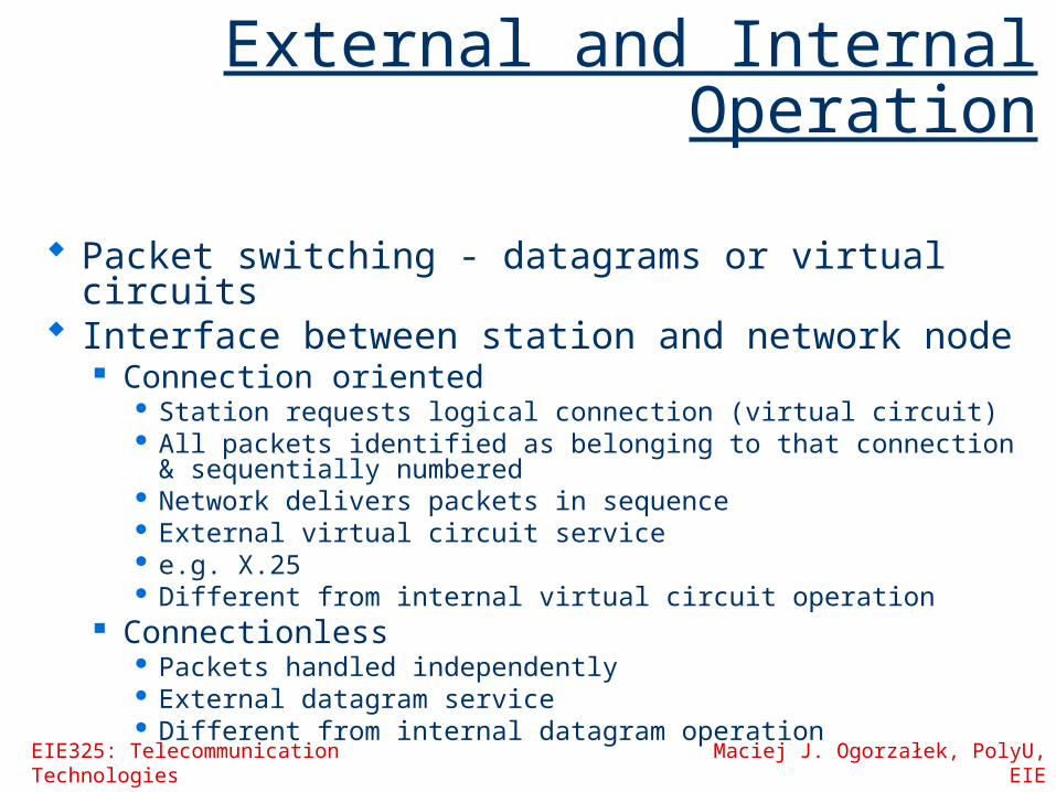
External and Internal Operation
Packet switching - datagrams or virtual circuits Interface between station and network node
Connection oriented Station requests logical connection (virtual circuit) All packets identified as belonging to that connection &
sequentially numbered Network delivers packets in sequence External virtual circuit service e.g. X.25 Different from internal virtual circuit operation
Connectionless Packets handled independently External datagram service Different from internal datagram operation
EIE325: Telecommunication Technologies Maciej J. Ogorzałek, PolyU, EIE
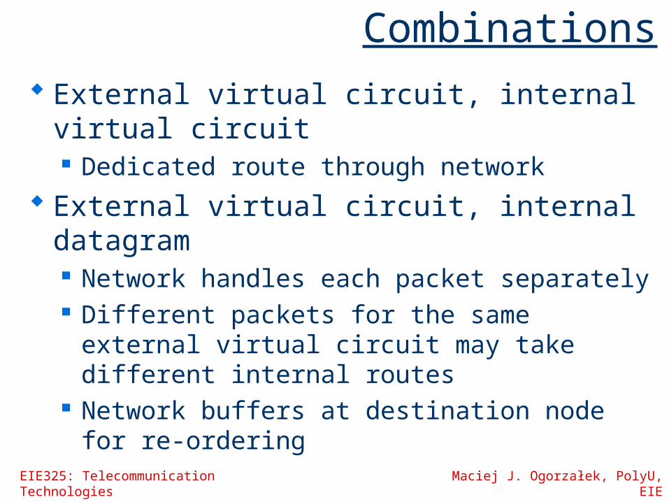
Combinations External virtual circuit, internal virtual
circuit Dedicated route through network
External virtual circuit, internal datagram Network handles each packet separately Different packets for the same external
virtual circuit may take different internal routes
Network buffers at destination node for re-ordering

EIE325: Telecommunication Technologies Maciej J. Ogorzałek, PolyU, EIE
Combinations
External datagram, internal datagram Packets treated independently by both
network and user External datagram, internal virtual
circuit External user does not see any
connections External user sends one packet at a time Network sets up logical connections

External Virtual Circuit
andDatagram
Operation

InternalVirtualCircuit
andDatagram
Operation

Virtual Circuit

EIE325: Telecommunication Technologies Maciej J. Ogorzałek, PolyU, EIE

Packet Switching