eight wheeled corridor tender kit - brassmasters corridor tender instructions… · 2 section 2:...
TRANSCRIPT

Brassmasters Scale Models
www.brassmasters.co.uk
LONDON & NORTH EASTERN RAILWAY
1928 - EIGHT WHEELED CORRIDOR TENDER KIT
Designed by Martin Finney
4MM SCALE OO - EM - P4
INSTRUCTIONS AND PROTOTYPE NOTES
PO Box 1137 Sutton Coldfield B76 1FU
Copyright Brassmasters 2016

1
SECTION 1: BRIEF HISTORICAL DETAILS The L.N.E.R. built these ten corridor tenders, numbered 5323 to 5332, in 1928 against Tender Order No. 50. The purpose of this type of tender was to allow the Flying Scotsman train to run, without stopping, between Kings Cross and Edinburgh, and yet allow the relief crew to travel off the engine footplate.
When new, these tenders were coupled to A1s (with long travel valve gear), and also to Class A3. From October 1936 these tenders were modified and then coupled to A4s Nos. 4482-90/98. The last corridor tender was removed from an A3 in September 1937.
The preserved A3, 4472 Flying Scotsman, is coupled to one of these tenders as modified for the A4 Class as are the preserved A4s, 4488 Union of South Africa and 4498 Sir Nigel Gresley.
The modifications for the A4 class consisted of:
(1) Replacing the original spoked wheels with disc wheels. (2) Increasing the width between the side sheets at the front end. This necessitated moving the front handrails towards the rear. At the same time, on the tenders behind 4488 to 4490, these handrails were increased in length by 3" to 4' 6". (3) Raising the height of the front and division plates to cab height and providing a fairing. (4) Removing the second lamp bracket on the left side of the back.
For a more detailed history of these tenders Part 2A of Locomotives of the L.N.E.R. published by the R.T.C.S. is essential reading. Other valuable sources of information and photographs are: For original condition A1/A3 Isinglass Drawings Drg.No.33 Locomotives Illustrated 25 - Ian Allan The Power of the A1s, A2s and A3s - J.S.Whiteley & G.W.Morrison - Oxford Publishing Co. The Gresley Pacifics - O.S.Nock - David & Charles Yeadon's Register of L.N.E.R. Locomotives - Volume One - Irwell Press LNER Reflections - BBC Hulton Picture Library - SLP For modified condition A4 Isinglass Drawings Drg.No.317 Yeadon's Register of L.N.E.R. Locomotives - Volume Two - Irwell Press East Coast Pacifics at work - P.N.Townend - Ian Allan The A4 Pacifics - P.N.Townend - Ian Allan Locomotives Illustrated 38 - Ian Allan The Power of the A4s - Brian Morrison - Oxford Publishing Co.

2
SECTION 2: CONSTRUCTING THE CHASSIS Note that many of the components handed left/right and care must be taken to ensure the correct component is used. I have not always identified left/right components separately but with care and common sense no problems should arise. Start by opening up the holes in the chassis frames and centre spacer (parts 1, 2 & 4) as follows:
1/16" to fit the compensation beam pivots 0.45mm to fit the wire for the brake hanger pivots and scoop stays - to fit the scoop casting 1.2mm to fit the front brake cross shaft 0.7mm in the brackets to fit the rear scoop cross shaft.
Fold over the axle slot reinforcing plates, on the chassis frames, through 180° with the half-etched line on the outside of the fold. Widen the slots so that the axles are a sliding fit. Fold up the appropriate (for the gauge being modelled) spacers (parts 3, 4 & 5) with the fold lines on the inside and solder in place in the chassis slots checking that the chassis is straight and square. Construct the front compensation beam by soldering the two halves (part 6) together. Cut a piece of 3/32" brass tubing to fit between the sides of the chassis frames and solder the beam in place, centrally. Fit the beam using a piece of 1/16" brass wire as the pivot. Similarly fit the rear beams to two pieces of tubing so that they pivot independently. They are soldered to the tubing near one end so that they will clear the axle slot reinforcing plates. Make up the wheel sets carefully, setting the back-to-back measurement with a gauge. Check that the beams are the correct way up, fit the wheel sets and test that the chassis works correctly. Wheel side control is limited by using the washers (part 37). Clearance between the wheels and the outside frames is limited, especially in P4, so it is probably wise to assemble the outside frames now so that clearances can be checked. Solder the brake hanger pivots, from 0.45mm wire, in place. Fold down the brackets for the rear scoop cross shaft on part 4 and assemble the water scoop as shown in Fig.3. Do not fit parts 31 & 32 at this time. Refit the wheel sets and retain as shown in Fig. 3. Assemble the brake hangers (parts 22, 23 & 24) and attach the hangers to the pivot wires. Check the clearance between the brake shoes and the wheels making any necessary adjustments. Complete the brake gear as shown in Fig.4. Lastly, attach parts 31 & 32, soldering the front end of part 32 to the wire from part 28. SECTION 3: CONSTRUCTING THE FRAMES / BUFFERBEAM / DRAGBEAM ASSEMBLY First emboss all the rivets on the frames (part 7) and part 8 and solder in place part 21 as shown in Fig.5. The embossing process on part 8 does tend to distort the metal making the component grow longer! This can be minimized by doing the embossing carefully and before the component is removed from the main fret. Fold up and solder together part 7 (see Fig.6), with all fold lines on the inside. Fold out the upper part of the footplate support brackets. Fold out the lower part of the brackets from part 8 and solder part 8 in place on the frames. Slide the bracket webs (part 9) into the grooves in the brackets and solder in place. Solder parts 14 and 15 to the front and the bufferbeam overlay (part 16) to the rear. Do not emboss the rivets or fold over the end of the lower step bracket which is a part of the bufferbeam overlay until it has been threaded through the slot in the upper step. Add part 17 in the slots in the bufferbeam overlay and solder in place before adding part 19. Fold up part 18 and solder in place. Solder together the two coupling hook laminations (part 54) and open out the hole to 0.6mm diameter. The Buckeye coupling (part B7) is pivoted in this hole with a piece of 0.6mm wire. If you wish to have the coupling in the working position then make a pin from .6mm wire which passes through the outer coupling hole and the coupling hook. Attach the completed coupling in the slot in the bufferbeam. The screw coupling, for use when the Buckeye coupling was not used, was carried on a bufferbeam hook. This is made from part 20 and a piece of 0.45mm wire as shown in Fig.5.

3
Assemble the buffers and solder in place. Clearance for the buffer shank is very tight, it is designed to move in the slot in part 7. Fold up the steps (parts 10, 11, 12 & 13) and solder in position. The holes in the frames correspond to the rivet positions and are used to assure correct positioning. Attach the vacuum tank (part W2) with the straps (part 33). Lastly, attach the remaining castings (W1, B1 & B2). The locating spigot on the axlebox castings will need to be cut off flush with the inside of the frames to clear the wheels. SECTION 4: CONSTRUCTING THE BODY Tack solder together (with the outsides facing) along their front edge, the two sides (parts 39 & 40). Now tack solder part 41 to the sides as shown in Fig.8. Drill the appropriate front handrail holes (0.8mm diameter). The two upper A4 class holes are have been explained in Section 1. For the A4 class saw down the side of part 41 to remove the piece shaded in Fig.8. Now remove the jig and separate the sides and for the A4 class reinstate the inner beading by soldering part 98 in place. The appearance of the etched beading can be improved by rounding the top edge. Make the jig for forming the curves in the top of the sides as shown in Fig.7. The only accurate dimension that is required is the diameter of the forming rod - 1/8". Tight clamping is important. Remove the rod locating brackets after you have completed the bend. Carefully form the curve in the front side sheets, around a rod of suitable diameter, using either Fig.1 or Fig.2 as a guide. Now solder the external beading to the sides. Start by straightening the beading by stretching it slightly. Clamp one end in the vice and pull the other end with a pair of pliers. First tack solder the beading to the rear end of the side aligning its upper edge with the edge of the fully etched area. Now pull the beading straight and tack solder at the front. Make a further six or so tacks along the side before, with plenty of flux and a hot iron, running all the tacks together. The bends at the front are tricky! I found the best method was to gently ease the beading to match the edge shape with a small pair of pliers, soldering each bend before proceeding to the next. Emboss all the rivets on parts 55, 56 & 58. Solder parts 54 & 55 together ensuring accurate alignment - the overlay overlaps part 54 at the front to form a recess into which part 58 fits. Also emboss the rivets in the division plate laminations (parts 79 & 80 or 86 & 87) before soldering the laminations together. Form the curve in the corridor top (part 54) in the same way as the sides using the same jig. Open up the holes for the vent pipes in the coal space hopper, then fold it up, making the top bends first before soldering the side edges together. Now check the fit of the right side (part 40), the corridor top (part 56) the tank top (parts 54 & 55) and the hopper (part 58). The corridor top fits in the slots in part 54 and in the etched recess under the beading at the top edge of the sides - see Fig.11. When satisfied with the fit solder the corridor top to the side ensuring the side overlaps the corridor top equally at each end. Emboss the rivets on part 43. Curve part 50 and solder in place in the slots in part 42 before soldering the two laminations of the back (parts 42 & 43) together. Drill out all the holes for the corridor connection piston rods, in parts 47, 48 & 51, .5mm diameter. Cut four lengths of 0.45mm wire and attach the small washer (part 49) at one end before filing the end flush. Fold up the corridor connection frame (part 47) and solder the floor to the sides. Pass two piston rods through the holes in the upper brackets (ensure a free sliding fit) before folding over the brackets and strengthening with solder. Attach part 48 in the slots in the floor. Fold the webs at the bottom of part 51 and modify part 52 as shown in Fig.10 before soldering together. Insert the lower piston rods followed by the springs and the outer frame. Space the frame from the sides using a block 2.8mm thick. Make sure all the piston washers are tight against their brackets before soldering the rods to the outer frame. Cut the rods off flush. You should now have a prototypically sprung corridor connection! Form and fit the handrail over the top of the corridor connection. Bend up the edges of the back steps (part 44) and solder in place. Now assemble the appropriate front plate as shown in Fig. 9 or Fig.13. The design uses two layers. Bear in mind the following:
The front plate is made in two separate assemblies (upper and lower) before soldering the two assemblies together.
Open up the various holes to fit the castings first.

4
Shape the step to the corridor door to fit the right hand front side sheet using the half-etched lines as a guide.
Bend up and fit the fire iron brackets and fit parts 70, 71 & 72 as appropriate before soldering the laminations together.
Emboss all rivets and fold out:
the brackets for the water valve levers and part B8 (A4 only)
the shovelling plate side
the step to the corridor door
before soldering the laminations together. Two slots will need filing in the upper side edges to fit around the etched beading on the inside of the tender sides. Solder 10 BA nuts, for body fixing, over the holes front and rear in the footplate (part 38) and fold up the raised footplate supports. The tender body, with most of the soldering done from inside, can now be assembled in the following order. First attach the right side to the back. Then attach the tank top locating the corridor top in the slots in part 54 followed by the division plate. Now solder the hopper in place under the front of part 55 and locating the corridor top in the slots in the hopper. Check that the side is straight. Now solder the left side to the back followed by the front plate. Lastly, locate the footplate between the etched recesses at the bottom of the sides and over the tabs on the back and front. Fit the raised footplate support (part 85 or 91) before fitting the appropriate raised footplate (part 84 or 90). Attach the vertical handrails at the front and rear using 0.45mm wire. Fit the lifting rings (part 59, 60, 61 & 62) to the coal hopper and tank top forming the rings around a 1/8" rod. The hinges on the A4 cab doors (part 97) are too long - shorten them by 0.5mm. Anneal them, by heating in a flame and bend to shape around a 0.45mm piece of wire. The hinge pins have been made too long so that they can be bent over to stop the doors falling off! The brackets to clip the tender and engine doors together can be made from wire. The paper corridor connection bellows are first lightly scored along the dotted lines and then cut out. Blacken with a pen before folding the bellows and gluing in place. The top flexible cover over the corridor connection is best made from thin black plastic sheet - from a bin liner (not provided!). After gluing in place part 53 is glued over the top. The remaining parts can now be fitted as shown in the diagrams. I hope you enjoy building and using your tender as much as I have enjoyed researching and designing it. If you have any problems with the kit or any criticisms or suggestions please contact Brassmasters. Best wishes Martin Finney January 1995

5

6

7

8

9

10

11

12
ETCHED COMPONENTS 1. Chassis frame - left side 51. Corridor connection outer frame 2. Chassis frame - right side 52. Corridor connection outer frame floor 3. Chassis spacer - front - 3 widths 53. Corridor connection hood retaining strip 4. Chassis spacer - centre - 3 widths 54. Tank top 5. Chassis spacer - rear - 3 widths 55. Tank top overlay 6. Compensation beam - (4) 56. Corridor top 7. Frame/bufferbeam/dragbeam assembly 57. Corridor top to rear casting cover plate 8. Frame/footplate brackets - (2) 58. Coal space hopper 9. Frame/footplate brackets webs - (16) 59. Lifting ring eye - (4) 10. Frame step - front - uf>per - (2) 60. Lifting ring base plate - (2) 11. Frame step - front - lower - (2) 61. Front lifting ring bracket - left 12. Frame step - rear - upper - (2) 62. Front lifting ring bracket - right 13. Frame step - rear - lower - (2) 63. Division plate vertical angle - (2) 14. Dragbeam overlay 64. Frontplate - lower - inner overlay 15. Drawbar pocket overlay - (4) 65. Frontplate - lower - outer overlay 16. Bufferbeam overlay 66. Corridor floor/side 17. Bufferbeam/frame web - (4) 67. Corridor door rain hood 18. Bufferbeam/frame bracket - (2) 68. Hinged flap 19. Overlay beneath buffers - (2) 69. Shovelling plate side 20. Screw coupling hook bracket 70. Coal door angle strip 21. Brake hanger pin retainer - (8) 71. Locker hinge - (4) 22. Brake hanger/shoe lamination - front axle - (4) 72. Locker rainstrip 23. Brake hanger/shoe lamination - second axle - (4) 73. Spare lamp bracket 24. Brake hanger/shoe lamination - rear axles - (8) 74. Water gauge bracket 25. Brake pullrod - (4) 75. Vent pipe bracket - (2) 26. Brake cross-shaft 76. Vent pipe flange - (2) 27. Front brake pull rod lamination - (4) 77. Water filler catch 28. Lever lamination - brake cylinder to cross-shaft - left - (2) PARTS FOR ORIGINAL CONDITION - A1/A3 29. Lever lamination - brake cylinder to cross-shaft - right - (2) 78. Lamp bracket - extended 30. Water scoop lever lamination - Scoop/rear cross-shaft - (2) 79. Division plate - front overlay 31. Water scoop lever - Cross-shaft/pull rod 80. Division plate - rear overlay 32. Water scoop pull rod 81. Coal rail 33. Vacuum tank strap - (2) 82. Frontplate - upper - inner overlay 34. Coupling hook lamination - (2) 83. Frontplate - upper - outer overlay 35. Screw coupling 84. Raised footplate 36. Drawbar 85. Raised footplate support 37. Washer - wheel side control PARTS FOR REBUILT CONDITION - A4 38. Footplate 86. Division plate - front overlay 39. Side - left 87. Division plate - rear overlay 40. Side - right 88. Frontplate - upper - inner overlay 41. Side - shaping/drilling jig 89. Frontplate - upper - outer overlay 42. Back - outer overlay 90. Raised footplate 43. Back - inner overlay 91. Raised footplate support 44. Step - back - (6) 92. Fairing front / right side 45. Lamp bracket - lower section - (2) 93. Fairing rear - left side 46. Lamp bracket - upper section - (2) 94. Corridor top to fairing bracket - (5) 47. Corridor connection door/frame 95. Angle piece - division plate 48. Corridor connection lower spring bracket 96. Angle piece - back 49. Corridor connection spring rod washer - (4) 97. Cab door - (2) 50. Corridor connection hood bracket 98. Side inner beading with hinge pins - (2)
13
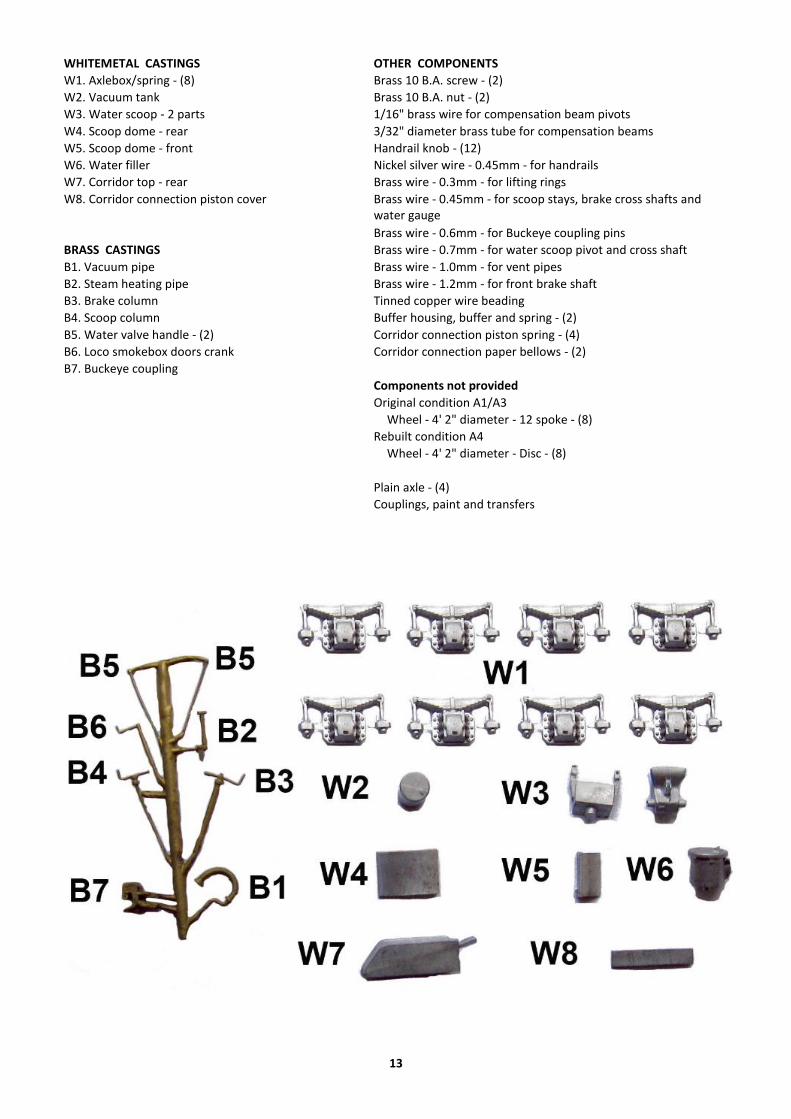
WHITEMETAL CASTINGS OTHER COMPONENTS
W1. Axlebox/spring - (8) Brass 10 B.A. screw - (2)
W2. Vacuum tank Brass 10 B.A. nut - (2)
W3. Water scoop - 2 parts 1/16" brass wire for compensation beam pivots
W4. Scoop dome - rear 3/32" diameter brass tube for compensation beams
W5. Scoop dome - front Handrail knob - (12)
W6. Water filler Nickel silver wire - 0.45mm - for handrails
W7. Corridor top - rear Brass wire - 0.3mm - for lifting rings
W8. Corridor connection piston cover Brass wire - 0.45mm - for scoop stays, brake cross shafts and water gauge
Brass wire - 0.6mm - for Buckeye coupling pins
BRASS CASTINGS Brass wire - 0.7mm - for water scoop pivot and cross shaft
B1. Vacuum pipe Brass wire - 1.0mm - for vent pipes
B2. Steam heating pipe Brass wire - 1.2mm - for front brake shaft
B3. Brake column Tinned copper wire beading
B4. Scoop column Buffer housing, buffer and spring - (2)
B5. Water valve handle - (2) Corridor connection piston spring - (4)
B6. Loco smokebox doors crank Corridor connection paper bellows - (2)
B7. Buckeye coupling Components not provided
Original condition A1/A3
Wheel - 4' 2" diameter - 12 spoke - (8)
Rebuilt condition A4
Wheel - 4' 2" diameter - Disc - (8)
Plain axle - (4)
Couplings, paint and transfers