eit-based slow and stored light in warm atoms
TRANSCRIPT
Laser & Photonics Reviews, July 22, 2011 1
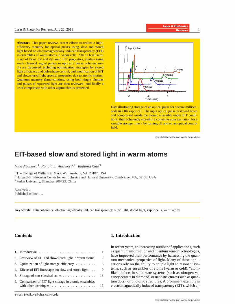
Abstract This paper reviews recent efforts to realize a high-efficiency memory for optical pulses using slow and storedlight based on electromagnetically induced transparency (EIT)in ensembles of warm atoms in vapor cells. After a brief sum-mary of basic cw and dynamic EIT properties, studies usingweak classical signal pulses in optically dense coherent me-dia are discussed, including optimization strategies for storedlight efficiency and pulseshape control, and modification ofEITand slow/stored light spectral properties due to atomic motion.Quantum memory demonstrations using both single photonsand pulses of squeezed light are then reviewed; and finally abrief comparison with other approaches is presented.
420Time (ms)
Input pulse
t=1ms
t=2ms
t=3ms
t=4ms
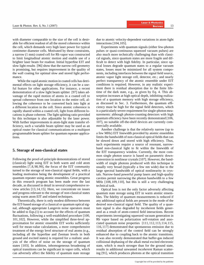
Data illustrating storage of an optical pulse for several millisec-onds in a Rb vapor cell. The input optical pulse is slowed downand compressed inside the atomic ensemble under EIT condi-tions, then coherently stored in a collective spin excitation for avariable storage timeτ by turning off and on an optical controlfield.
Copyright line will be provided by the publisher
EIT-based slow and stored light in warm atoms
Irina Novikova1, Ronald L. Walsworth2, Yanhong Xiao3
1 The College of William& Mary, Williamsburg, VA, 23187, USA2 Harvard-Smithsonian Center for Astrophysics and Harvard University, Cambridge, MA, 02138, USA3 Fudan University, Shanghai 200433, China
Received: . . .Published online: . . .
Key words: spin coherence, electromagnetically induced transparency, slow light, stored light, vapor cells, warm atoms
Contents
1. Introduction . . . . . . . . . . . . . . . . . . . . . . 1
2. Overview of EIT and slow/stored light in warm atoms 2
3. Optimization of light storage efficiency . . . . . . . . 5
4. Effects of EIT lineshapes on slow and stored light . . 9
5. Storage of non-classical states . . . . . . . . . . . . . 13
6. Comparison of EIT light storage in atomic ensembleswith other techniques . . . . . . . . . . . . . . . . . 16
1. Introduction
In recent years, an increasing number of applications, suchas quantum information and quantum sensor technologies,have improved their performance by harnessing the quan-tum mechanical properties of light. Many of these appli-cations rely on the ability to couple light to resonant sys-tems, such as ensembles of atoms (warm or cold), “atom-like” defects in solid-state systems (such as nitrogen va-cancy centers in diamond) or nanostructures (such as quan-tum dots), or photonic structures. A prominent example iselectromagnetically induced transparency (EIT), which al-
e-mail: [email protected]
Copyright line will be provided by the publisher

2 I. Novikova et al.: EIT-based slow and stored light in warm atoms
lows controlled manipulations of the optical properties ofatomic or atom-like media via strong coupling of a near-resonant optical signal field and collective long-lived en-semble spin by means of a strong classical optical controlfield [1,2]. EIT has become a versatile tool for realizationof controllable atom-light coupling, such as the manipula-tion of optical pulse propagation through atomic and atom-like media via slow [3,4,5] and stored light [6,7,8,9].
One of the exciting potential applications of EIT andslow and stored light is for practical realization of aquantum memory. This rapidly evolving area of researchhas been reviewed in several publications over the lastdecade [10,11,12,13,14,15,16]. In this manuscript we fo-cus on experiments aimed at optimizing EIT-based slowand stored light using warm atoms contained in vapor cellsof various configurations. The key difference between coldand warm atomic ensembles is the thermal motion of warmatoms, which produces significant Doppler broadening ofoptical transitions. However, the broadening of the two-photon spin transition can be minimized by working incollinear geometry (e. g., co-propagating control and sig-nal fields). The residual Doppler broadening caused bysmall mismatch of the two fields’ wavelengths can be prac-tically eliminated by restriction the motion of atoms in theregion smaller than a microwave transition wavelength (forexample, by adding an inert buffer gas), thereby operat-ing in a Dicke narrowing regime for the two-photon tran-sition [17]. Thus, warm atomic ensemble can be compa-rably practical for coherent manipulations of atomic spinsusing EIT as cold atoms [7,18,19,20,21,22]. In addition,warm-vapor-cell experiments have several attractive fea-tures, including relative simplicity of design and easy con-trol over large atomic ensembles. A typical vapor cell is asealed glass cylinder or sphere containing a small amountof solid metal (Rb or Cs). Hence the atomic vapor concen-tration can be easily controlled by changing the tempera-ture of the cell. Moreover, any unwanted external magneticfields can be effectively eliminated by placing the atomicvapor cell in a high-permeability magnetic shielding en-closure. The interaction time of warm atoms with EIT laserfields is extendable to several milliseconds by introducinga few torr of an inert buffer gas into the vapor cell to re-strict the motion of alkali metal atoms to slow diffusion;or by employing an anti-relaxation wall coating on the in-ner surface of the vapor cell. In addition, recent progressin chip-scale atomic clocks [23] and magnetometers [24]employing EIT and related effects clearly demonstrate thepotential for dramatic scaling down and commercializa-tion of atomic vapor cell-based technology, including foreducational purposes.
This manuscript is organized as follows. Section 2gives a brief summary of the basic principles of idealizedthree-level EIT systems and typical experimental resultsfor slow and stored light using warm atoms. Section 3describes general algorithms for optimization of an EIT-based quantum memory based on slow and stored lightand their recent experimental verification. Section 4 dis-cusses modifications to the idealized description of EIT
and slow/stored light arising from the motion of warmatoms, as well as related experiments in buffer gas andwall-coated vapor cells. Experimental demonstrations ofthe storage of non-classical states of light in warm atomicensembles are described in Section 5; the same section dis-cusses additional complications that arise for non-classicalsignal storage compare to that of weak coherent signals.Section 6 provides a schematic comparison of ensembleEIT schemes with alternative light storage techniques.
2. Overview of EIT and slow/stored light inwarm atoms
2.1. Basic principles of EIT in an idealizedthree-level scheme
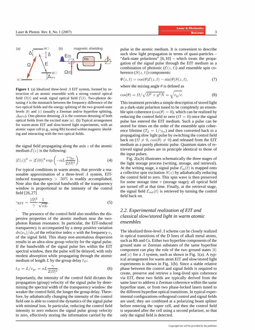
Following the formalism of Ref. [10], we consider propa-gation of a weak optical signal (or probe) pulse with en-velopeE(z, t) and a strong (classical) optical control fieldwith a Rabi frequency envelopeΩ(z, t) [25] in a resonantΛ-type atomic medium, as illustrated schematically in Fig-ure 1. In general, the propagation of a signal pulse can bedescribed by the following equations [6,10], assuming aslowly-varying envelopeE of the signal field and definingthe optical polarizationP =
∑
|b〉〈a|/√N of the|a〉−|b〉
transition and the spin coherenceS =∑ |b〉〈c|/
√N be-
tween states|b〉 and|c〉:
(∂t + c∂z)E(z, t) = ig√NP (z, t), (1)
∂tP (z, t) = −γP (z, t) + ig√NE(z, t) +
iΩ(t− z/c)S(z, t), (2)
∂tS(z, t) = −γbcS(z, t) + iΩ(t− z/c)P (z, t).(3)
Here,c is the speed of light in vacuum,N is the number ofatoms in the interaction region,γ andγbc are the decoher-ence rates of the optical and spin transitions, respectively,g is the atom-field coupling constant (assumed to be thesame for both the|a〉 − |b〉 and |a〉 − |c〉 optical transi-tions),λ is the signal field wavelength,L is the length ofthe sample, andαL = 2g2N/γc is the unsaturated opticaldepth on the|b〉 − |a〉 optical transition.
Under the conditions of two-photon Raman resonance(i.e., whenνc − νs = ∆bc) the control field createsstrong coupling between the signal fieldE and a collectiveground-state spin coherence (“spin wave”)S in the atomicensemble, which results in strong suppression of resonantabsorption for both the control and signal fields – i.e., theeffect known as electromagnetically induced transparency(EIT). In the ideal case of no spin decoherence (γbc = 0)one can achieve100% transmission of the optical fieldswith EIT. For any realistic system, however, non-zeroγbcleads to residual absorption even under EIT conditions. Inthe case of steady state optical fields and assuming no ab-sorption for the strong control fieldΩ, the amplitude of
Copyright line will be provided by the publisher
Laser & Photon. Rev.1, No. 1 (2007) 3
|c⟩
|b⟩
|a⟩
Ω E
δ∆
∆HFS
E(t)
Ω(t)
Rb
magnetic shielding(a) (b)
Figure 1 (a) Idealized three-levelΛ EIT system, formed by in-teraction of an atomic ensemble with a strong control opticalfield Ω(t) and weak signal optical fieldE(t). Two-photon de-tuningδ is the mismatch between the frequency difference of thetwo optical fields and the energy splitting of the two ground-statelevels |b〉 and |c〉 (usually a Zeeman and/or hyperfine splitting,∆HFS). One-photon detuning∆ is the common detuning of bothoptical fields from the excited state|a〉. (b) Typical arrangementfor warm-atom EIT and slow/stored light experiments, with anatomic vapor cell (e.g., using Rb) located within magnetic shield-ing and interacting with the two optical fields.
the signal field propagating along the axisz of the atomicmediumE(z) is the following:
|E(z)|2 = |E(0)|2 exp(
−αLγγbc2|Ω|2
)
. (4)
For typical conditions in warm atoms, that provide a rea-sonable approximation of a three-levelΛ system, EIT-induced transparency> 50% is readily accomplished.Note also that the spectral bandwidth of the transparencywindow is proportional to the intensity of the controlfield [26,27]
γEIT =|Ω|2γ
1√αL
. (5)
.The presence of the control field also modifies the dis-
persive properties of the atomic medium near the two-photon Raman resonance. In particular, the EIT-inducedtransparency is accompanied by a steep positive variationdn(νs)/dνsof the refractive indexn with the frequencyνsof the signal field. This sharp non-anomalous dispersionresults in an ultra-slow group velocity for the signal pulse.If the bandwidth of the signal pulse lies within the EITspectral window, then the pulse will be delayed, with onlymodest absorption while propagating through the atomicmedium of lengthL by the group delaytD:
tD = L/vgr = αLγ
2|Ω|2 . (6)
Importantly, the intensity of the control field dictates thepropagation (group) velocity of the signal pulse by deter-mining the spectral width of the transparency window: theweaker the control field, the longer the group delay. There-fore, by adiabatically changing the intensity of the controlfield one is able to control the dynamics of the signal pulsewith minimal loss. In particular, reducing the control fieldintensity to zero reduces the signal pulse group velocityto zero, effectively storing the information carried by the
pulse in the atomic medium. It is convenient to describesuch slow light propagation in terms of quasi-particles –“dark-state polaritons” [6,10] – which treats the propa-gation of the signal pulse through the EIT medium as acombination of photonic (E(z, t)) and ensemble spin co-herence (S(z, t)) components:
Ψ(z, t) = cos(θ)E(z, t) − sin(θ)S(z, t), (7)
where the mixing angleθ is defined as
cos(θ) = Ω/√
Ω2 + g2N =√
vg/c. (8)
This treatment provides a simple description of stored lightas a dark-state polariton tuned to be completely an ensem-ble spin coherence (cos(θ) = 0), which can be realized byreducing the control field to zero (Ω = 0) once the signalpulse has entered the EIT medium. Such a pulse can bestored for times on the order of the ensemble spin coher-ence lifetime (T2 = 1/γbc) and then converted back to apropagating slow light pulse by switching the control fieldback on (Ω 6= 0, cos(θ) 6= 0) and released from the EITmedium as a purely photonic pulse. Quantum states of re-trieved signal pulses are in principle identical to those ofthe input pulses.
Fig. 2(a,b) illustrates schematically the three stages ofthe light storage process (writing, storage, and retrieval).At the writing stage, a signal pulseEin(t) is mapped ontoa collective spin excitationS(z) by adiabatically reducingthe control field to zero. This spin wave is then preservedfor some storage timeτ (storage stage); all optical fieldare turned off at that time. Finally, at the retrieval stage,the signal fieldEout(t) is retrieved by turning the controlfield back on.
2.2. Experimental realization of EIT andclassical slow/stored light in warm atomicensembles
The idealized three-levelΛ scheme can be closely realizedin optical transitions of the D lines of alkali metal atoms,such as Rb and Cs. Either two hyperfine components of theground state or Zeeman substates of the same hyperfinecomponent can play the role of the two ground states|b〉and|c〉 for aΛ system, such as shown in Fig. 1(a). A typ-ical arrangement for warm atom EIT and slow/stored lightexperiments is shown in Fig. 1(b). Since a stable relativephase between the control and signal fields is required tocreate, preserve and retrieve a long-lived spin coherencevia EIT, these two fields are typically derived from thesame laser to address a Zeeman coherence within the samehyperfine state, or from two phase-locked lasers tuned tothe different hyperfine optical transitions. In typical exper-imental configurations orthogonal control and signal fieldsare used; they are combined at a polarizing beam splitterbefore entering the vapor cell, and then the control fieldis separated after the cell using a second polarizer, so thatonly the signal field is detected.
Copyright line will be provided by the publisher

4 I. Novikova et al.: EIT-based slow and stored light in warm atoms
Figure 2 Cartoon representation of the light storage process. Toprow (a) shows time variation of the control fieldΩ(t), which ison during the writing and retrieval stages, and is turned offforthe storage period. Second row (b) illustrates light storage underideal conditions (atomic medium with very high optical depthand insignificant loss), in which the signal field pulse is sloweddown and fully compressed inside the EIT medium during thewriting stage, and then completely mapped (stored) into thespinwave and finally retrieved without losses. The bottom row (c)shows the same process for more realistic conditions (moderateoptical depth, some loss); in this case the slow light group veloc-ity vg is not sufficiently small to compress the whole signal pulseinside the EIT medium, so that the front of the pulse escapes thecell before control field is turned off; and at the same time the tailof the pulse is not stored since it does not enter the medium dur-ing the writing stage. Practical considerations of the EIT mediumlength and possible pulse compression (proportional to theopti-cal depth) set the fundamental limitation of maximum achievablelight storage efficiency, even for insignificant loss duringthe stor-age period.
For some experiments, it is possible to phase-modulatethe output of a single laser at a microwave frequencymatching the atomic hyperfine splitting, and then use thestrong field at unmodulated frequencyνc as the controlfield and one of the first modulation sidebands at fre-quencyνc + ∆HFS as the signal field. In this case bothfields perfectly spatially overlap and have the same polar-ization, but it is more challenging to isolate the signal fieldfor detection after interaction with atoms. Often the signaland control fields are resolved by monitoring the beat fre-quency between each field and a third (reference) field ata shifted RF frequency. Another potential complication ofthis phase modulation method is the presence of the othermodulation sideband at the frequencyνc − ∆HFS. Whilethis field is far-detuned from all optical transitions, its pres-ence may still affect the signal field transmission and dy-namics through enhanced four-wave mixing processes (seediscussion below).
Usually, an atomic vapor cell is a sealed Pyrex glasssphere or cylinder that contains a small amount of solidor liquid alkali metal. The density of atoms in the vaporphase is determined by thermodynamic equilibrium, and
can be controlled by the cell temperature. In a “vacuum”cell, there is no buffer gas added and the alkali atoms moveballistically from wall to wall, except for occasional alkali-alkali collisions. Since atoms are usually completely ther-malized as a result of a single collision with a wall, theatomic ground state coherence lifetime in a vacuum vaporcell is limited by the mean time-of-flight of atoms throughthe laser beam,γbc ∝ 〈v〉T /a, wherea is the radius ofthe beam and the mean atomic velocity in thermal equilib-rium 〈v〉T =
√
8kT/πm (k is the Boltzmann constant,mis atomic mass andT is absolute temperature). There aretwo commonly employed methods to extend the coherencelifetime of warm atoms: (i) atomic motion can be effec-tively slowed down by use of an inert buffer gas, causingalkali atoms to move diffusively through the laser beam;or (ii) the atomic ground-state coherence can be preservedduring wall collisions by coating the inside of the glasswalls with an anti-relaxation coating. With the buffer gasmethod the atom-laser interaction time can be extended byseveral orders of magnitude [28,29]:
γbc = 2.4052D
a21
1 + 6.8λ/a, (9)
whereD = D0 · p0/p is the diffusion constant for motionof the alkali atom through the buffer gas,λ = 3D/〈v〉T isthe alkali atoms mean free path,p is the buffer gas pres-sure, andD0 andp0 are the corresponding values at onestandard atmosphere. Standard buffer gases include inertatoms (He, Ne, Ar) or simple molecules (N2); these gasesare characterized by small collisional dephasing cross-section for the ground states of alkali metal atoms (detailedinformation on diffusion constants and collisional cross-sections of alkali metal atoms with various buffer gassesis available, for example, in Ref. [28]). However, excitedelectronic states are much more sensitive to buffer gas col-lisions, resulting in a homogeneous broadening of the op-tical transitions.
Fig. 3 shows typical experimental results for slow andstored light in a87Rb vapor cell, with 22 Torr of Ne buffergas in this example. A single laser tuned in the vicinityof the 5S1/2 → 5P1/2 (D1) line of 87Rb served as thecontrol optical field. Phase modulation of the laser out-put using an electro-optical modulator (EOM) transferredapproximately2% of the total light power into each firstorder sideband, creating signal and Stokes optical fieldswith negligible variations in control field amplitude. Smallvariation of the modulation frequency around the hyper-fine splitting of 6.835 GHz controlled the two-photon de-tuningδ; and desired pulseshapes for the signal field wereproduced by applying a calibrated voltage to the modulatorduring the writing stage. In such a configuration the bestslow and stored light was observed using circularly polar-ized optical fields in aΛ system formed by the control fieldon theF = 2 → F ′ = 2 transition and the signal field ontheF = 1 → F ′ = 2 transition.
In slow light experiments the control field intensity isideally constant; and hence the signal pulse propagateswith constant reduced group velocity. Fig. 3(a) shows a
Copyright line will be provided by the publisher

Laser & Photon. Rev.1, No. 1 (2007) 5
measured delay of440 µs for the output signal pulse, ex-ceeding the full width half maximum of the input pulse(350 µs), with a corresponding fractional delay of 1.3.However, interaction with the atomic ensemble also broad-ened the output signal pulse to500 µs due to the finite EITtransmission linewidth. In the most common stored lightrealization [Fig. 3(b)] the control field is constant duringwriting and retrieval stages (“flat” control); but it is turnedoff during the storage using, for example, an acousto-optical modulatior (AOM). In such cases the signal pulse,slowly propagating inside the atomic ensemble as a darkstate polariton, is converted into a non-propagating spinwave (i.e., is “stored” in the atomic medium) by turningoff the control field power. In the experimental examplesshown in Fig. 3(b), the front portion of the signal pulse es-caped the cell before storage due to insufficient fractionaldelay and pulse broadening (“leakage”). The stored frac-tion of the signal pulse was then retrieved by turning thecontrol field back on after a few milliseconds. The shapesof the retrieved signal pulses were nearly identical; theyalso were good matches to the slow light pulse shownin Fig. 3(a) (accounting for the missing front of the sig-nal pulse due to leakage). However, longer storage timeresulted in exponential reduction of the recovered signalpulse energy due to spin wave decoherence during storage.Relatively long (> 1 ms) measured spin coherence life-times have been achieved in warm atom EIT-based storedlight experiments by using high-quality magnetic shield-ing to minimize the effect of stray laboratory magneticfields; and by mitigating the effect of atomic thermal mo-tion using a relatively large laser beam diameter (approxi-mately 1 cm) and high buffer gas pressure [30,17].
Substantially longer spin coherence lifetimes are achiev-able in vapor cells with an anti-relaxation wall coating.Paraffin is the most commonly used anti-relaxation wallcoating for alkali atom vapor cells [31,32,33,34]. Ground-state coherence times up to a second (i.e., up to 10,000 wallcollisions before spin decoherence) were achieved usingparaffin-coated cells [31,33,35,36,37], and Zeeman co-herence lifetime up to 60 seconds was recently reportedin vapor cells with novel alkene coatings [38]. However,the dynamics of light-atom interactions is more compli-cated with wall-coated cells than with buffer gas cells dueto long coherence lifetimes “in the dark” (outside the laserbeam), as will be discussed in more detail in Sec 4.
At low optical depth (i.e., low atomic density and/orsmall vapor cell length) the ground-state coherence life-time is mainly determined by environmental parameterssuch as the finite interaction time of atoms with the opti-cal fields, residual magnetic field inhomogeneities, atom-atom and atom-wall collisions [28], etc. At high opticaldepth, however, other processes can become dominant andshorten the ground-state coherence lifetime: e.g., radiationtrapping [39,40,41]. Due to residual absorption at finiteoptical depth there is a non-zero population of the excitedatomic state in the presence of the optical fields, even un-der EIT conditions, resulting in spontaneous emission ofphotons in arbitrary directions and with arbitrary phases.
543210-1Time (ms)
input pulse
543210-1Time (ms)
Input pulse
(a)
(b)storage
time
inputpulse
control field
inputpulse
control field
Figure 3 Examples of measured signal field after propagationthrough a warm atom EIT medium: (a) slow light (constant con-trol field); and (b) stored light (flat control field during signalpulse writing and retrieval; zero control field during storage). Inboth cases the control field power was900 µW.
These spontaneously emitted photons do not generally ex-perience EIT due to wave-vector mismatch with the con-trol field. Thus in optically thick vapor there is a high prob-ability for such photons to be reabsorbed, leading to fur-ther spontaneous emission, reabsorption, etc. Such “radia-tion trapping” can significantly degrade the dark state andunderlies EIT.
At high atomic density, EIT performance can also bedegraded by competing nonlinear processes, such as stim-ulated Raman scattering and four-wave mixing [26,42,43,44,45,46,47]. In this case one cannot neglect the off-resonant coupling between levels|b〉 and |a〉, which re-sults in generation of a Stokes optical field at the frequencyνc −∆HFS. Such a situation is well-modeled by a simpledouble-Λ system, where the output signal and Stokes fieldamplitudes are the results of interference between “tra-ditional” EIT and four-wave mixing [26,42,48,49]. Bothcontinuous-wave EIT spectra and signal pulse propagationdynamics can be affected by the presence of a seeded orspontaneously generated Stokes field, with both signal andStokes fields observed at the reading stage of the light stor-age process [50,51,52]. On the other hand, such four-wavemixing processes can be used to create strong correlationand entanglement between the signal and Stokes fields [53,54,55].
Copyright line will be provided by the publisher
6 I. Novikova et al.: EIT-based slow and stored light in warm atoms
3. Optimization of light storage efficiency
3.1. Limited memory efficiency due to finiteoptical depth
We define the light storage memory efficiencyη as theprobability of retrieving an incoming single photon afterstorage in an ensemble EIT system; or, equivalently, asthe energy ratio between the initial and retrieved signalpulses [56,57]:
η =
∫ τ+T
τ |Eout(t)|2dt∫ 0
−T|Ein(t)|2dt
. (10)
Even under the idealized assumptions of no incoher-ent losses in the system, realization of an EIT quantummemory with100% storage efficiency requires simultane-ous fulfillment of two conditions. First, as illustrated inFig. 2(b), the group velocityvg of the signal pulse in-side the medium has to be low enough to spatially com-press the entire input pulse within the lengthL of the en-semble: i.e., to avoid “leaking” the front edge of the sig-nal pulse past the EIT medium or cutting off the pulsetail when the control field is shut off as part of the stor-age procedure. This first condition equates to requiringthe signal pulse durationT to be short enough so thatTvg ≪ L. The second condition is that all spectral com-ponents of the incoming signal pulse must fit inside theEIT transparency window to minimize absorption and re-sulting spontaneous emission losses, which equates to re-quiring1/T ≪ ∆ωEIT ≃
√αLvg/L [6]. The simultane-
ous satisfaction of both conditions is possible only at veryhigh optical depthαL ≫ 1 [6,56]. As mentioned above,it is very challenging to maintain high transparency andlong ground-state coherence time as the density of atomsincreases. Thus, for practical purposes it is important tooptimize EIT memory performance for moderately highoptical depthαL > 1. Such an imperfect but “realisticallyoptimized” situation is illustrated in Fig. 2(c): the tailsofthe signal pulse are not stored in the EIT medium due tofinite optical depth; there is some modest decoherence dur-ing storage; and the output pulse shape is slightly modifieddue to finite EIT spectral width. Degradation due to thesefactors must be balanced to achieve maximum signal pulsestorage efficiency.
3.2. Optimization procedure
In a series of recent theoretical works, Gorshkovet al.considered a wide range of processes for optimal storageand retrieval of photon wave packets in atomic ensem-bles [56,58,59,60,61]: EIT; far-off-resonant Raman; anda variety of spin echo methods including ensembles en-closed in a cavity, inhomogeneous broadening, and high-bandwidth non-adiabatic storage (1/T ∼ αLγ) [61]. Thiscomprehensive analysis revealed several general strategies
for stored light optimization; and demonstrated that thehighest achievable memory efficiency depends fundamen-tally only on the optical depthαL, since the strength of thephotonic coupling to the collective excitation in the atomicensemble, relative to spontaneous decay, grows with opti-cal depth [56]. The analysis of Gorshkov et al. also showedthat under optimized conditions the writing stage is thetime reversal of the retrieval stage. This time reversal sym-metry implies that for degenerate lower levels of aΛ sys-tem,stored signal pulses are optimally retrieved by a con-trol field propagating in the opposite direction with re-spect to the writing stage (i.e., “backward retrieval”) [56,59]. In contrast, “forward retrieval” (co-propagating writ-ing and retrieval control fields) is more efficient when non-degenerate hyperfine states are used for light storage [59],due to the non-zero momentum of the spin wave for a non-degenerateΛ system.
Furthermore, the above analysis demonstrated that foreach optical depth, there exists a unique spin waveSopt(z)that provides the maximum memory efficiency. Thus, thefocus of the optimization process becomes identifying amatched pair of control and signal pulse fields to map thesignal pulse reversibly onto the optimal spin wave.
retrieval stage
xxxxxxxxxxxxxxxxxxxxxxxxxxxxxxxxxxxxxxxxxxxxxxxxxxxxxxxxxxxxxxxxxxxxxxxxxxxxxxxxxxxxxxxxxxxxxxxxxxxxxxxxxxxxxxxxxxxxxxxxxxxxxx
writing stage
invert control fieldinput signal pulse εin(t)
control field Ω(t)
spin wave S(z)
signal pulse leakage
0-T
retrieved signal pulse εout(t)
(a)
(b)
τ+Tτ
0-T
xxxxxxxxxxxxxxxxxxxxxxxxxxxxxxxxxxxxxxxxxxxxxxxxxxxxxxxxxxxxxxxxxxxxxxxxxxxxxxxxxxxxxxxxxxxxxxxxxxxxxxxxxxxxxxxxxxxxxxxxxxxxxx
next writing stage inverted, normalized signal pulse
εin(t)
0-T
(c)
0-T
τ+Tτ
iterated signal pulse
control field Ω(t)
control field Ω(τ-t)
spin wave S(z)
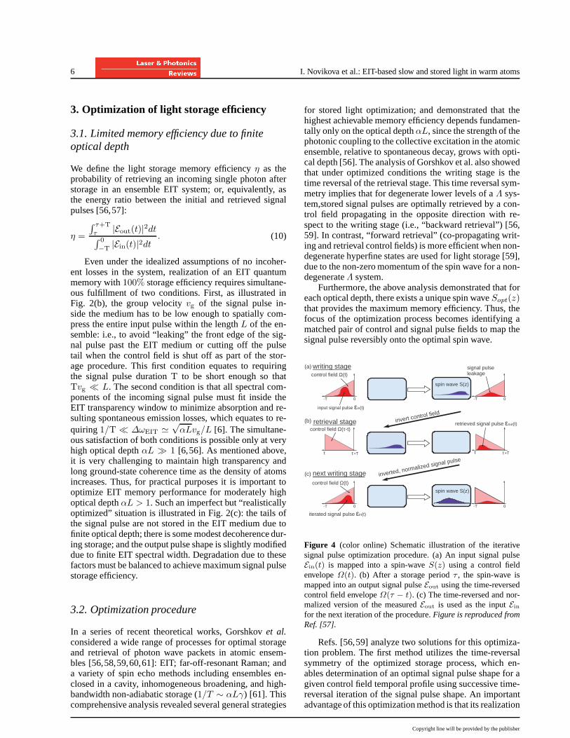
Figure 4 (color online) Schematic illustration of the iterativesignal pulse optimization procedure. (a) An input signal pulseEin(t) is mapped into a spin-waveS(z) using a control fieldenvelopeΩ(t). (b) After a storage periodτ , the spin-wave ismapped into an output signal pulseEout using the time-reversedcontrol field envelopeΩ(τ − t). (c) The time-reversed and nor-malized version of the measuredEout is used as the inputEin
for the next iteration of the procedure.Figure is reproduced fromRef. [57].
Refs. [56,59] analyze two solutions for this optimiza-tion problem. The first method utilizes the time-reversalsymmetry of the optimized storage process, which en-ables determination of an optimal signal pulse shape for agiven control field temporal profile using successive time-reversal iteration of the signal pulse shape. An importantadvantage of this optimization method is that its realization
Copyright line will be provided by the publisher
Laser & Photon. Rev.1, No. 1 (2007) 7
does not require any prior knowledge of the system param-eters. Fig. 4 shows schematically the iterative optimizationprocedure adapted to forward retrieval [59]: (a) the inputsignal pulseEin(t) is mapped into a spin waveS(z) in-side the atomic vapor for a given optical depth and con-trol Rabi frequency envelopeΩ(t) (bothEin(t) andΩ(t)are assumed to vanish outside of time interval[0, T ]); (b)an output signal pulseEout(t) is forward retrieved usingthe time-reversed control field pulseΩ(T − t); (c) then atime-reversed and normalized version of the retrieved sig-nal pulseEout(T − t) becomes the input signal pulse forthe next iteration cycle.
These steps are repeated several times until the shapeof the retrieved pulseEout(t) is identical to the time-reversed input signal pulseEin(T − t) (attenuated becauseof imperfect memory). Under reasonable assumptions [62]the resulting pulse shape provides the highest storage effi-ciency possible for a given optical depth and control fieldprofile. The success of this optimization procedure is basedon linearity of the EIT light storage process; such that ateach step the stored spin wave can be decomposed into alinear superposition of orthogonal spin wave eigenmodes,for which the optimal spin wave results in maximum stor-age efficiency, and consequently maximum contribution tothe retrieved signal pulse. Thus, after several iterationstheoptimization procedure converges to the optimized inputsignal pulse shape for a given optical depth and controlfield temporal profile.
The second optimization method allows maximally ef-ficient storage and retrieval of an arbitrary signal pulseshapeEin(t), which requires determination of an opti-mized control fieldΩ(t). As shown in [59], this optimizedcontrol field can be most easily calculated for the idealizedcondition of mappingEin(t) into a “decayless” spin waves(z) in a semi-infinite atomic EIT medium with no opticalpolarization decay and for a given optical depthαL. Thisdecayless spin waves(z) allows unitary reversible storageof an arbitrary input signal pulse, which establishes a 1-to-1 correspondence betweenEin(t) and given control field.As also shown in Ref. [59], this same control field mapsthe input signal pulse onto the optimal spin waveSopt(z)in a realistic EIT medium with finite length and polariza-tion decay.
3.3. Experimental verification
The light storage optimization procedures outlined abovehave been successfully tested experimentally using weakclassical signal pulses in warm Rb atomic ensembles.Experimental realizations [50,57] of the iterative time-reversal optimization method confirmed the three primarypredictions of the underlying theory [56,59]: (i) efficiencygrows with each iteration until the input signal field con-verges to its optimal pulse-shape; (ii) the result of the opti-mization procedure is independent of the initial (trial) sig-nal pulse-shape; and (iii) the final, optimal light storage
0.15
0.10
0.05
0.00
Sig
na
l fie
ld
6004002000-200Time (µs)
0.15
0.10
0.05
0.00 Sig
na
l fie
ld
6004002000-200Time (µs)
0.15
0.10
0.05
0.00
Sig
na
l fie
ld
6004002000-200Time (µs)
0.15
0.10
0.05
0.00
Sig
na
l fie
ld
6004002000-200Time (µs)
0.15
0.10
0.05
0.00
Sig
na
l fie
ld
6004002000-200Time (µs)
0.15
0.10
0.05
0.00
Sig
na
l fie
ld
6004002000-200Time (µs)
6
4
2
0
Co
ntr
ol fie
ld (
mW
)
6004002000-200Time (µs)
Writing stage Retrieval stage
Input pulse
Leakage Retrievedpulse
Iteration #0
Iteration #1
Iteration #2
inverted andrenormalized retrieved pulse
inverted andrenormalized retrieved pulse
storage time
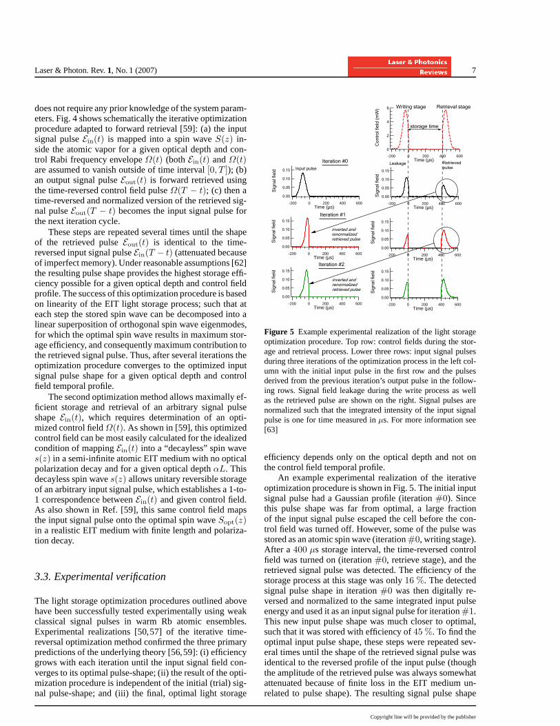
Figure 5 Example experimental realization of the light storageoptimization procedure. Top row: control fields during the stor-age and retrieval process. Lower three rows: input signal pulsesduring three iterations of the optimization process in the left col-umn with the initial input pulse in the first row and the pulsesderived from the previous iteration’s output pulse in the follow-ing rows. Signal field leakage during the write process as wellas the retrieved pulse are shown on the right. Signal pulses arenormalized such that the integrated intensity of the input signalpulse is one for time measured inµs. For more information see[63]
efficiency depends only on the optical depth and not onthe control field temporal profile.
An example experimental realization of the iterativeoptimization procedure is shown in Fig. 5. The initial inputsignal pulse had a Gaussian profile (iteration#0). Sincethis pulse shape was far from optimal, a large fractionof the input signal pulse escaped the cell before the con-trol field was turned off. However, some of the pulse wasstored as an atomic spin wave (iteration#0, writing stage).After a 400 µs storage interval, the time-reversed controlfield was turned on (iteration#0, retrieve stage), and theretrieved signal pulse was detected. The efficiency of thestorage process at this stage was only16 %. The detectedsignal pulse shape in iteration#0 was then digitally re-versed and normalized to the same integrated input pulseenergy and used it as an input signal pulse for iteration#1.This new input pulse shape was much closer to optimal,such that it was stored with efficiency of45 %. To find theoptimal input pulse shape, these steps were repeated sev-eral times until the shape of the retrieved signal pulse wasidentical to the reversed profile of the input pulse (thoughthe amplitude of the retrieved pulse was always somewhatattenuated because of finite loss in the EIT medium un-related to pulse shape). The resulting signal pulse shape
Copyright line will be provided by the publisher

8 I. Novikova et al.: EIT-based slow and stored light in warm atoms
15
10
5
0
Con
trol
fiel
d (m
W)
2001000-100Time(µs)
15
10
5
0
Con
trol
fiel
d (m
W)
2001000-100Time(µs)
0.15
0.10
0.05
0.00
Sig
nal f
ield
2001000-100Time(µs)
0.15
0.10
0.05
0.00
Sig
nal f
ield
2001000-100Time(µs)
(a)
(a')
(b)
(b')
Figure 6 (Color online) Example measurements of light storagefor two differently-shaped signal pulses (a′, b′) using in each casethe calculated optimal control fields (a,b) for the writing stage(t < 0). Input signal pulse shapes are shown in black dotted lines.The same graphs also show the signal pulses leakage (solid blacklines for t < 0) and retrieved signal pulses using flat controlfields (red dashed lines) or time-reversed control fields (red solidlines) at the retrieval stage (t > 100 µs). The temperature of thecell was60.5 C (αL = 24) [50].
provided the highest storage efficiency for a given controlfield (and fixed optical depth). For example, in the experi-ment shown in Fig. 5, the optimal signal field pulse shape(achieved at the end of iteration#2) yielded47 % storageefficiency.
In this and all other experiments the resultant opti-mized signal pulse shapes are in excellent agreement withtheoretical calculations using Eqs.(1-3) and effective pa-rameters for the optical depth and control field Rabi fre-quency [50] to make a connection between realistic87Rbatoms (which have sixteen unique states associated withthe D1 optical transition) and an idealized 3-levelΛ-system. Similarly, optimized control field envelopes ob-tained from numerical solutions of Eqs.(1-3) for arbitrarysignal pulses provided similar light storage efficiency asthe iterative signal pulse method. Fig. 6 shows examplesof measured light storage for two randomly chosen signalfield envelopes using the calculated optimal control fieldsfor the writing stage and two different retrieval methods.First, a flat retrieval control field of the same intensity wasused to retrieve both pulses, which resulted in the sameoutput pulse [red dashed curves in (a′, b′)] independent ofthe input signal pulse shape, because the excitation wasstored in the same optimal spin wave in each case. Sec-ond, an optimal control field was used for retrieval (i.e., atime-reversed version of the writing control field), whichyielded output signal pulses that were time-reversed copiesof the corresponding input signal pulses (moderately at-tenuated due to finite loss in the system). This observedtime-reversal symmetry between stored and retrieved sig-nal pulse shapes illustrates the mutual consistency of thetwo optimization methods.
Experimental tests have also been performed of thetheoretical prediction of light storage memory efficiencyincreasing with optical depth, by repeating the iterative
signal pulse optimization procedure for a wide range ofwarm Rb atomic densities [50]. Fig. 7 shows memory effi-ciency as a function of optical depth measured for four dif-ferent values of a flat control field. Each experimental datapoint correspond to the storage efficiency measured for op-timized signal pulses obtained using the iterative optimiza-tion procedure for each particular control field power andoptical depth. These results indicate that for moderatelylow optical depth (αL ≤ 25) the optimization procedurefollows the prediction of the simple theory, yielding a max-imum efficiency that is independent of control field power,reaching a highest efficiency of45%. However, at higheroptical depth the experimental results deviated from the-ory, showing reduced light storage efficiency at high opti-cal depth. Several reasons for this non-ideal behavior wereidentified. One of them is decay of the spin wave. Nonethe-less, if the signal pulse duration is short enough, the effectof spin-wave decay is negligible during the writing andretrieval processes; and the optimization procedures, de-veloped for an ideal system with no spin decay, can applyto realistic atomic ensembles with spin decoherence. In allcases, maximum storage efficiency is achieved for identi-cal optimal signal and/or control field pulse shapes aftertaking into account the reduction of storage efficienciesby the factore−τ/ts due to spin wave decoherence dur-ing the storage timeτ ; here,ts is the spin wave decay timeconstant. Note that as the optimal pulse duration increaseswith optical depth for a given control power, due to den-sity narrowing of the EIT window [see Eq.(5)], spin decaybecomes significant during writing and retrieval, break-ing time-reversal symmetry and reducing the efficiency oflight storage at higher optical depth. This problem can bealleviated in many practical cases by using higher controlfield power, and hence shorter optimal signal pulses.
Fig. 7 also shows that spin wave decay cannot accountfor the observed lower-than-expected optimized storageefficiency forαL ≥ 25, although time-reversal symme-try is still preserved [50]. One of the possible causes forthe lower efficiency is resonant four-wave mixing (FWM),which becomes significant at large optical depth. This pro-cess is well-modeled by a simple double-Λ system, wherethe output signal and Stokes field amplitudes are the re-sults of interference between “traditional” (single-Λ) EITsystem and their coupled propagation under FWM condi-tions. The description of the coupled propagation of thesignal and Stokes fields is in good agreement with exper-imental observations [49,52]. Under these conditions thesimple dark state polariton treatment of light storage is notvalid anymore. The spin wave becomes dependent on acombination of signal and Stokes fields, which does notpreserve each of them individually [51,52]. While detri-mental for storage of quantum states of light, resonantfour-wave mixing may be useful for classical slow lightapplications, as it offers additional control mechanisms forsignal pulse propagation by, for example, controlling theamplitude of a seeded Stokes field. Moreover, by tuningthe central frequency of the input signal field around thetwo-photon resonance, one can achieve longer pulse delay
Copyright line will be provided by the publisher

Laser & Photon. Rev.1, No. 1 (2007) 9
0.6
0.4
0.2
0.0
Effi
cien
cy
100806040200
Optical depth
P=8mW P=16mW
(i)
(ii) (iii)
(iv)
Figure 7 (Color online) Measured light storage efficiency as afunction of optical depth (colored diamond symbols) for twodif-ferent power values of flat control fields. Thin (i) and thick (ii)black solid lines show the theoretically predicted maximumef-ficiency assuming no spin-wave decay except for an efficiencyreduction by a factor of0.82 during the100 µs storage period,respectively. Dashed red (iii) and blue (iv) lines are calculated ef-ficiencies for same two control fields assuming spin wave decaywith a500 µs time constant during all three stages of the storageprocess (writing, storage, retrieval) [50].
and/or amplification [49]. Finally, note that for very highoptical depth both optimization procedures fail when con-trol field absorption become significant.
3.4. Pulseshape control
The optimization methods outlined above can be em-ployed together to satisfy the two key requirements fora practical light storage quantum memory: (i) reachingthe highest possible memory efficiency in an ensemblewith limited optical depth; and (ii) precisely controllingthe temporal envelope of the retrieved signal pulse. Thelatter goal can be achieved by adjusting the control fieldenvelopes for both writing and retrieval stages. Since themaximum memory efficiency is achieved when the in-put signal pulse is mapped onto an optimal spin waveS(z), determined by an optimal control fieldΩ(t) that isunique for eachαL [56,59], theretrievalcontrol fieldΩ(t)(τ < t < τ + T) that mapsS(z) onto the desired tar-get output signal pulseEtgt(t) can be determined by thesame control field optimization procedure together withthe time-reversal symmetry principle for optimized lightstorage [57,50,56,59]. Thus the control field that retrievesthe optimal spin waveS(z) into Etgt(t) after storage is thetime-reversed copy of the control field that stores the time-reversed target pulseEtgt(τ − t) into S(z) [64].
As shown in Fig. 8, this method was employed experi-mentally in warm Rb atoms to achieve signal-pulse-shape-preserving storage and retrieval,i.e., the target output sig-nal pulse was identical to the input pulse when accounting
0.2
0.1
0.0
Sig
nal f
ield
2001000-100
Time (µs)
0.2
0.1
0.0
Sig
nal f
ield
2001000-100
Time (µs)
15
10
5
0
Con
trol
fiel
d (m
W)
2001000-100Time (µs)
Writing RetrievalStorage(a)
(b) Before the cell After the cell
εin(t) εout(t)
Input pulse Leakage
Ω(t)
-T 0 τ+Tτ
0.40.20.0
1.00.50.0
S(z)
z/L
Output pulse
Figure 8 (Color online) Measured control (a) and signal (b)fields in pulse-shape-preserving storage of a “positive-ramp” sig-nal pulse in warm Rb vapor using a calculated optimal controlfield envelopeΩ(t). During thewriting stage (t < 0), the inputpulseEin(t) is mapped onto the optimal spin-waveS(z) [insetin (a)], while a fraction of the pulse escapes the cell [leakage in(b)]. After astoragetimeτ , the spin-waveS(z) is mapped into anoutput signal pulseEout(t) during theretrievalstage. The dashedblue line in (b) shows the target output pulse shape calculated forrealistic conditions in this experiment.
for finite loss during the storage process. The measuredoutput signal pulse [solid black line in Fig. 8(b)] matchesvery well the target “positive ramp” pulse shape [dashedblue line in the same figure]. Moreover, since this methodis based on universal symmetries for optimal light storage,it is likely to be indispensable for applications in both clas-sical [65] and quantum optical information processing in awide range of experimental arrangements, such as ensem-bles enclosed in a cavity [58,66], the off-resonant regime[56,58,59], non-adiabatic storage (i.e., storage of pulsesof high bandwidth) [61], and ensembles with inhomoge-neous broadening [60], including Doppler broadening andline broadening in solids.
4. Effects of EIT lineshapes on slow andstored light
4.1. Using measured EIT spectra to determineslow light delay
Characterization of slow and stored light for a particularmedium often begins with the associated static EIT res-onance. Recent work [67] showed that a simple realisticmodel of EIT spectra allows accurate prediction of theslow-light pulse delay from two easily measurable param-eters: the linewidth and the off-resonant transmission level(which serves as a proxy for the medium’s effective opti-cal depth). Fig. 9(a) shows a typical measured EIT spec-trum for warm Rb atoms, with the signal field transmissionnormalized to the off-two-photon-resonance transmission.
Copyright line will be provided by the publisher

10 I. Novikova et al.: EIT-based slow and stored light in warm atoms
Figure 9 (a) Example measured EIT intensity spectrum withnormalized contrast and background levels. Solid gray lineis thedata while the dashed dark line is a fit to a skew-Lorentzian. F:signal intensity above background away from EIT resonance (the“floor”); A: amplitude of EIT peak; C: difference between EITpeak and100% transmission (the “ceiling”). (b) Measured slow-light delays (solid squares) and predictions (hollow squares)based on accessible EIT line-shape parameters. Good agreementis shown over a large range of pulse delays and laser intensities.Figure is reproduced from Ref. [67], which also includes experi-mental and model details.
For a Lorentzien EIT lineshape, the optical depth of themediumαL can be determined from the off two-photonresonance transmission “floor”F , of the EIT spectrum:F = exp (−αL). Also, the EIT FWHM linewidth (W) andpeak transmission1−C together determine the coherencedecay and optical pumping rate. The predicted maximumslow light delayτ can then be expressed from the aboveeasily measurable parameters asτmax = −ln(F )/W .As shown in Fig. 9(b), good agreement was found be-tween the measured maximum slow light delay and thedelay predicted from the simple model of [67] using easilymeasured EIT spectrum parameters. In general, slow lightwith large pulse delay and high transmission efficiency isobtained for a low EIT spectral floor F (i.e., high opti-cal depth) and large EIT transmission amplitude A (i.e.,
low loss). Thus the above characterization procedure us-ing static EIT lineshape measurements can be an efficient,practical method to optimize slow light performance. Thistechnique should be applicable to a wide range of slowlight media, for which static resonance line shapes can beeasily extracted.
Note that the above procedure is quantitatively validfor a Lorenztian (or near-Lorentzian) EIT lineshape; butcan be still used as a qualitative guide for non-Lorentzianlineshapes. In practice, several factors can cause a non-Lorentzian EIT lineshape, such as atomic motion, a nonuni-form laser beam profile [68,69], four wave mixing ef-fects [26,48,49,70], and various other spectral narrowingand reshaping phenomena [27]. We will next focus on theeffects of atomic motion in buffer and coated cells on EITspectra, slow light dynamics and stored light efficiency.
4.2. Ramsey-narrowed EIT lineshapes in buffergas cells
laser beam
glass cell (a)
x
y
(b)
Figure 10 (Color online) (a) Example path for atoms diffusing inand out of the laser beam in a buffer gas cell. (b) Calculated EITlineshapes resulting from diffusive return of atomic coherence tothe laser beam. Solid red curve: an example for one particulardiffusion history (Ramsey sequence), with equal time spentinthe laser beamtin = τD before and after diffusing in the darkfor time tout = 20τD , whereτD is the mean time to leave thebeam given by the lowest-order diffusion mode. Dashed blackcurve: weighted average over all Ramsey sequences, yielding thecharacteristic “pointy” EIT lineshape resulting from diffusion-induced Ramsey narrowing.Figure is reproduced from Ref. [72].
To increase the atom-light interaction time in warmvapor cells, a few torr of inert buffer gas is often addedto restrict the fast, thermal atomic motion. A buffer gasalso reduces two-photon Doppler broadening of the EITmedium’s optical transitions through the Dicke narrow-ing effect [71]. It has been common practice to calculateEIT decoherence due to atom diffusion out of the laserbeam using only the lowest diffusion mode, as in Eq. (9)above, which yields a Lorentzian EIT lineshape in the non-power-broadened regime. Note, however, that this lowest-diffusion-mode calculation implicitly assumes that thereis insignificant diffusive return of atomic coherence to the
Copyright line will be provided by the publisher

Laser & Photon. Rev.1, No. 1 (2007) 11
laser beam – an assumption that is often incorrect for prac-tical warm atom EIT systems. In particular, when the laserbeam diameter is much smaller than that of the vapor celland other decoherence processes (e.g. due to inhomoge-nous magnetic fields) are insignificant, atoms can diffusein and out of the laser beam multiple times without losingtheir coherence, as shown schematically in Fig. 10(a). Inthis case, each atom in the EIT ensemble effectively ex-periences a Ramsey-like sequence of interactions with thelaser interspersed with coherent evolution in the dark (out-side the laser beam). The resultant contribution of one suchsequence to the EIT spectrum is well modeled by the Ram-sey fringes as shown in Fig. 10(b). Summing over con-tributions to the EIT spectrum from all atoms undergoingsuch diffusive motion in-and-out of the laser beam, and us-ing probabilistic weights for different Ramsey fringe spec-tra governed by the diffusion equation, one derives a non-Lorentzian, “pointy” EIT lineshape, with a sharp centralpeak that results from constructive interference of the cen-tral fringes of all diffusing atoms together with largely de-structive interference of the other Ramsey fringes [72].
Both experiment and theory have demonstrated theexistence and ubiquity of this “diffusion-induced Ram-sey” narrowing effect in warm atom buffer gas EIT sys-tems. As shown in Fig. 11(a) for typical Rb EIT oper-ating conditions in a buffer gas cell, the measured EITresonance for a 1.5 mm diameter laser beam has a full-width half-maximum (FWHM) of 740 Hz, whereas thecalculated FWHM≈ 20 kHz if one assumes (incorrectly)that the coherence lifetime is set by the lowest-order dif-fusion mode out of the beam. As also shown in Fig. 11(a),the measured EIT line shape for the 1.5 mm diameterlaser beam is spectrally narrower near resonance than aLorentzian: this sharp central peak is the characteristicsignature of diffusion-induced Ramsey narrowing. In con-trast, the measured EIT resonance in the same buffer gasRb cell for a 10 mm diameter laser beam (with the same to-tal intensity as the 1.5 mm beam) is well fit by a Lorentzianline shape with FWHM of 400 Hz [see Fig. 11(b)], whichis in good agreement with the calculated FWHM using thelowest-order diffusion mode, and is consistent with onlysmall fraction of atoms leaving this relatively large di-ameter beam and returning during the intrinsic coherencelifetime (set by buffer gas collisions and diffusion to thecell walls). A theoretical model based on multiple returnof atoms into the laser beam found good agreement withmeasured EIT spectra [73]. In general, the contrast of thenarrow peak of the EIT spectrum decreases when buffergas pressure is higher, laser power is higher or the laserbeam is larger. The sharp peak linewidth is mainly deter-mined by the intrinsic coherence decay rate (i.e., it is notlimited by the time to diffuse out of the laser beam on asingle pass), and is relatively insensitive to power broad-ening.
The pointy EIT lineshape commonly exhibited inbuffer gas cells poses a challenge for high-efficiency slowand stored light. To avoid large signal pulse absorption andreshaping, the bandwidth of the signal pulse should be sig-
Figure 11 (Color online) Measured Rb EIT line shapes (inred) and fits using a Lorentzian line shape (dashed lines), withlaser beam diameters of approximately (a) 1.5 mm and (b) 10mm in a 3 Torr Ne cell with total incident laser intensity of 1µW/mm2. Fitted Lorentzian parameters are the amplitude, off-resonant background, and full widths of approximately (a) 1400and (b) 400 Hz. Broad solid curve in (a) is a 20 kHz FWHMLorentzian, the expected line shape for a coherence lifetime setby the lowest-order diffusion mode out of the laser beam, withamplitude set equal to the peak measured amplitude for illustra-tive purposes.Figure is reproduced from Ref. [72].
nificantly less than the sharp peak linewidth. However, theslow light delay for such a pulse is often not long enoughfor high-efficiency light storage, because only a small partof the atoms contribute to the narrow peak: i.e., the ef-fective optical depth for the useful sharp peak of the EITspectrum is much smaller than the nominal optical depth.For instance, for a Ramsey narrowed EIT experiments de-scribed in Ref. [74], a Gaussian waveform was employedfor the signal pulse with a (relatively long) temporal lengthof 1 ms, which experienced a group delay of about 450µsfor a control field power of 50µW. Note that a larger con-trol field intensity was used at the retrieval (600µW) to in-crease the EIT linewidth and thereby minimize losses dur-ing release and propagation of the retrieved signal pulse.The 1/e storage time was about 500µs, correspondingto a decoherence rate consistent with the linewidth of thesharp peak of the EIT spectrum at low laser intensities, butmuch longer than the lowest-order diffusive escape timecalculated from Eq. (9). For highest efficiency of stored
Copyright line will be provided by the publisher

12 I. Novikova et al.: EIT-based slow and stored light in warm atoms
light in buffer gas cells, it is desirable to use a laser beamdiameter that is large enough to maximize the coherencelifetime, and also to have enough laser power to providehigh EIT transmission and efficient readout. Given practi-cal constraints on laser power, one must determine an op-timal laser beam diameter to maximize light storage effi-ciency.
Firstenberget al. carried out a comprehensive studyof the effects on EIT of thermal atomic motion in buffergas cells, including an assessment of the effect of mis-alignment of the control and signal fields (i.e., differingk vectors when these fields are not co-linear) [75,76].They found that the EIT lineshape broadens and its con-trast degrades as the angle between the control and signalfields increases, due to residual Doppler broadening of thetwo-photon EIT resonance [76]. Moreover, when a non-collimated beam such as a diffracted beam is considered,the signal field transmission becomes a function of posi-tion within the laser beam, similar to the intensity distri-bution in diffraction. This feature was utilized to eliminateand manipulate effects of the optical diffraction by adjust-ing the EIT two-photon detuning [77,78]. Similar effectswere also exploited to slow and store images, both of theinput light amplitude and phase, using EIT in warm atombuffer gas cells [80]. In warm buffer cells, diffusion of co-herently prepared atoms is an issue that must be addressedin high resolution and long time image storage. A “phaseshift” method [81] and storing the image’s Fourier plane[82,83] were proposed to offset the effects of diffusion;and both proved effective.
4.3. Dual-structure EIT lineshapes in cells withanti-relaxation wall coatings
Coating an atomic vapor cell’s glass inner walls with ananti-relaxation layer such as paraffin is another way to pro-long atomic coherence lifetimes by reducing the effectsof atom-wall collisions on atomic hyperfine and Zeemanstates. An EIT linewidth as narrow as 1 Hz has been re-alized in such paraffin-coated cells (no buffer gas) [35];and recent improvements in coating material have enabledminute long coherence lifetimes [84,85]. Coated cellsare actively being used for magnetometer [86], atomicclock [87] and quantum optics [88,89,90] applications.In comparison to buffer gas cells, coated cells do not suf-fer from collisional decoherence of excited states due tothe buffer gas, which destroys quantum correlations in her-alded photon generation experiments [91]. Thus, coatedcells may be the best candidate for the use of warm vaporcell in single-photon experiments [89].
The typical EIT lineshape in a coated cell has a dualstructure [88,92]. A narrow central peak results from mul-tiple coherent atom-light interactions, as the atoms makemany wall collisions before suffering decoherence, withthe linewidth of the narrow peak set by the intrinsic atomiccoherence lifetime, which is determined by coating qual-ity, cell geometry, magnetic field inhomogeneity, etc. A
Figure 12 (a) Measured EIT spectrum from a coated cell, ex-hibiting the characteristic dual structure EIT lineshape.An ex-panded view is given of the narrow central feature of the EITspectrum. (b) Measured light storage resulting from the coatedcell EIT spectrum shown in (a); 8 ms of storage time is real-ized, but with low storage efficiency.Figure is reproduced fromRef. [93].
broad pedestal underlying the narrow peak arises fromatom-light interaction during a one-time pass of atomsthrough the laser beam. Slow and stored light in coatedcells can operate on two different time scales correspond-ing to signal pulses with spectral widths that fit within thelinewidth of either the narrow peak or broad pedestal struc-tures of the EIT lineshape. For instance, in Ref. [88], slowlight in a coated cell was observed for signal pulse widthsof both 5 ms and 50µs. However, the fractional pulse delaywas limited to only about30%, due to radiation trapping,which prevents further increase of efficiency at higher op-tical depth. In general for coated cells, the, stored lightefficiency is low, although the storage time can be long(≃ 8 ms was observed in [93]).
The low stored light efficiency is determined by fun-damental issues associated with the ballistic motion ofatoms in coated cells. For warm atoms, Zeeman EIT(grounds states are degenerate Zeeman levels) has muchlower contrast than for hyperfine EIT (ground states arenon-degenerate hyperfine levels), because for Zeeman EITthe two-photon transition matrix elements have oppositesigns for the two excited states (D1 line of87Rb, for ex-ample) which are partly mixed under Doppler broadening.Hence ground state Zeeman coherence induced via EITcoupling through the two excited states will destructivelyinterfere [94]. However, for hyperfine EIT to work in acoated cell, the atoms must not move beyond the range ofthe hyperfine wavelength, which≈ 4 cm for87Rb. (Atomswith smaller hyperfine splitting and hence longer hyper-fine wavelength are also being investigated to overcomesuch issues [95]). In addition, a high intensity laser beam
Copyright line will be provided by the publisher
Laser & Photon. Rev.1, No. 1 (2007) 13
with diameter comparable to the size of the cell is desir-able for efficient readout of all the stored coherence withinthe cell, which demands very high laser power for typicalcentimeter diameter cells. Motivated by these constraints,a narrow (1 mm) coated cell for Rb vapor was constructedto limit longitudinal atomic motion and enable use of abrighter laser beam for readout. Initial hyperfine EIT andslow light results [96] show that the narrow cell geometryis promising, but requires improvement in the quality ofthe wall coating for optimal slow and stored light perfor-mance.
While the rapid atomic motion in coated cells has detri-mental effects on light storage efficiency, it can be a use-ful feature for other applications. For instance, a recentdemonstration of a slow light beam splitter [97] takes ad-vantage of the rapid motion of atoms in a coated cell tospread coherence from one location to the entire cell, al-lowing the coherence to be converted back into light ata different location in the cell. Since atomic coherence israpidly shared within a coated cell, light from different lo-cations is phase coherent. The light splitting ratio providedby this technique is also adjustable by the laser power.With further improvements in atom-light state transfer ef-ficiency, such a variable beam splitter may be used as anoptical router for classical communications or a multiportprogrammable beam splitter for quantum repeater applica-tions.
5. Storage of non-classical states
Following the proof-of-principle demonstrations of stored(classical) light using EIT in both warm and cold atomensembles [7,8,98,99], the focus of the EIT communityturned to the storage of non-classical signal fields, with aleading motivation being the development of a practicalquantum repeater using atomic ensembles. Great progressin this research program has been made over the lastdecade, as discussed in detail in several comprehensive re-view articles [13,14,15]. Here, we concentrate on issuesand progress relevant to the storage of non-classical statesusing warm atom EIT and related techniques.
Theoretically, there is only modest difference betweenthe EIT-based storage of a classical or quantum optical sig-nal, although appropriate Langevin noise operators mustbe added to Eqs.(1) to account for the effects of quantumfluctuations, following a well-established procedure [100,101,102]. However, while the simplified three-level ap-proximation for atomic ensemble EIT works sufficientlywell for mean-value calculations, a more comprehensivetreatment of the energy level structure of real atoms (e.g.,including all the hyperfine and Zeeman levels in bothground and excited states) is required for a realistic anal-ysis of the effect of noise on the storage of quantumstates [103]. In addition, inhomogeneous broadening ofoptical transitions can be significant in vapor cells, whichcan adversely affect the fidelity of quantum state storage
due to atomic velocity-dependent variations in atom-lightinteractions [104,105].
Experiments with quantum signals (either few-photonpulses or quasi-continuous squeezed vacuum pulses) arealso much more technically challenging than with classi-cal signals, since quantum states are more fragile and dif-ficult to detect with high fidelity. In particular, since op-tical losses degrade quantum states to a regular vacuumstates, losses must be minimized for all system compo-nents, including interfaces between the signal field source,atomic vapor light storage cell, detector, etc.; and nearlyperfect transparency of the atomic ensemble under EITconditions is required. However, in any realistic experi-ment there is residual absorption due to the finite life-time of the dark state, e.g., as given by Eq. 4. This ab-sorption increases at high optical depth, inhibiting realiza-tion of a quantum memory with high storage efficiency,as discussed in Sec. 3. Furthermore, the quantum effi-ciency must be high for the signal field detectors, whichis a particularly severe requirement for single-photon mea-surements: although photon-counting detectors with highquantum efficiency have been recently demonstrated [106,107], no suitable off-the-shelf devices are currently com-mercially available.
Another challenge is that the relatively narrow (up toa few MHz) EIT linewidth provided by atomic ensembleslimits the bandwidth of non-classical optical fields that canbe slowed down and stored with high efficiency. Thus,such experiments require a source of resonant, narrow-band non-classical light to fit within the linewidth ofthe EIT transparency window. Currently, the most com-mon single photon source is based on parametric down-conversion in nonlinear crystals [107]. However, the band-width of single photons produced with this technique isusually very broad (typically a few nm wide) due to thelarge spectral bandwidth of optical nonlinearity in crys-tals. Narrow-band powerful pump lasers and high-qualitycavities permit narrowing the photon bandwidth to a fewMHz [108,109,110], but this is still a very challengingtechnical task.
Optical loss is not the only factor adversely affectingquantum state storage using EIT in warm atomic ensem-bles. The fidelity of quantum measurements is reduced ifany additional optical fields are present in the mode of thedesired non-classical signal field. The quality of a quan-tum signal is also degraded by incoherent fields gener-ated as a result of atom-control field interactions. Recentexperiments investigating squeezed vacuum generation inRb vapor based on polarization self-rotation and asso-ciated quantum noise properties [111,112,113,114,115,116,117] demonstrated that spontaneous emission due toresidual absorption of the control field can be stronglyenhanced due to coupling back to the atomic transitions.It was also recently demonstrated that buffer-gas inducedcollisional dephasing of the alkali metal excited electronicstate, which is much stronger than for the ground state,results in additional unwantedincoherentRaman scatter-ing [91], which produces photons at the optical transition
Copyright line will be provided by the publisher
14 I. Novikova et al.: EIT-based slow and stored light in warm atoms
frequency, rather than the Raman resonance frequency;and thus does not provide the photon-spin coupling thatunderlies all EIT effects. These spontaneous and incoher-ent Raman photons must be eliminated from the signalfield detection channel either by spectral filtering, whichadds further technical complication; or by reduction of thecollision rate, e.g., by lowering the buffer gas pressure,which reduces the atom-light interaction time and thus de-grades the quality of the EIT resonance.
In addition, it is essential to cleanly separate the sig-nal and control fields at the detection stage after interac-tion with atomic ensembles. The closeness of the signaland control optical frequencies limits the utility of spec-troscopic filtering methods, since traditional dispersiveel-ements and interference filters cannot efficiently resolvetwo optical fields separated by only a few GHz. Applica-tion of spatial filtering is limited as well in a warm atomsystem, since nearly collinear propagation of the signaland control fields is required to avoid large two-photonDoppler broadening, which occurs when(kc−ks)·vatoms
becomes comparable to or larger than the ground-statelinewidth. For example, an angle mismatch as small as0.25 mrad between the signal and control fields producesabout 100 kHz Doppler broadening for warm atoms. Suchstringent requirement of co-linearity of the signal and con-trol fields makes spatial filtering inadequate for the neces-sary separation of the fields at the detection stage. To ad-dress this challenge, multiple spectral filtering stages havebeen required, such as optically-pumped filtering cellsand/or Fabry-Perot etalons [91,118,119].
5.1. Single photon storage
Over the last decade, the prospects of practical realizationof a quantum repeater based on atomic ensembles usingthe DLCZ protocol, proposed by Duan, Lukin, Cirac andZoller in 2001 [120], stimulated many research groupsto investigate EIT-based interactions of single- or a few-photon pulses with both warm and cold atomic ensem-bles. The DLCZ protocol produces entanglement betweentwo distant atomic ensembles by probabilistic entangle-ment of pairs of neighboring ensembles followed by en-tanglement swapping between adjacent pairs to extend thecreated entanglement; the procedure is then repeated for aseries of separated ensemble pairs to extend the entangle-ment to arbitrary distances. In the traditional realizationof the DLCZ protocol, both ensembles in a pair separatedby some distanceL less than the absorption length of thephoton communication channel, are illuminated with anidentical off-resonance classical pump field until a spon-taneous Raman occurs producing a single spin wave andemission of a correlated single Stokes photon in the for-ward direction. The photon outputs from both ensemblesare directed to interfere on a beam-splitter and measuredwith two sensitive photodetectors. It is important that theprobability of Stokes emission is kept low to ensure nodouble excitations within one ensemble or simultaneous
excitation in both ensembles. If only one Stokes photon isemitted, the click in one (and only one) of the two detec-tors indicates the creation of maximally entangled statesbetween the two ensembles. If zero or more than one pho-tons are detected, then the process must be repeated. Afterentanglement is successfully created within each of twoadjacent ensemble pairs, with one ensemble in each en-tangled pair being in close proximity, the entanglement isextended to the two widely separated ensembles in the twopairs (separated by2L) by performing an entanglementswapping operation between the two co-located ensembles(one from each originally entangled pair). Such swappingis accomplished by illuminating the two co-located ensem-bles with a resonant classical control field that under EITconditions converts the previously created spin excitationin each ensemble into an anti-Stokes photon. The photonoutputs from the two co-located ensembles are then inter-fered on a beamsplitter and measured. Since each emittedanti-Stokes photon is still entangled with the atomic spinexcitation in the corresponding pair of originally entan-gled ensembles (each separated by distanceL), a click inone (and only one) of the output photodetectors signifiesentanglement creation between the two widely separatedatomic ensembles in the two pairs. The same steps can berepeated to extend the entanglement even further over suc-cessive pairs of ensembles each separated by distanceL.The proposed protocol can be largely insensitive to manyrealistic losses, and predicts polynomial (rather than ex-ponential) scaling of entanglement preparation time withdistance. Further theoretical development of the originalDLCZ protocol is reviewed in Ref. [121].
Experimental realization of of the full DLCZ proto-col or its variants has not yet been achieved, due to manytechnical challenges for both cold and warm atoms. Nev-ertheless, many essential steps for a DLCZ-type quantumrepeater have been experimentally demonstrated, includ-ing quantum correlation and entanglement between theinitial single-photon pulse emitted in the spontaneous Ra-man process and the later single-photon pulse retrieved un-der EIT conditions [118,122,123,124,125,126,127,128,129]. In these demonstration experiments, much like thefirst part of the DLCZ protocol outlined above, the first(Stokes) photon is produced by spontaneous Raman gen-eration under the action of a strong off-resonance laserfield, which simultaneously creates a spin coherence inthe atomic ensemble. This coherence is later read out bya resonant optical field under EIT and slow/stored lightconditions, resulting in the generation of a second, corre-lated (anti-Stokes) photon. Quantum mechanical correla-tions between these two photons can be verified by mea-suring their photon-number fluctuations using a Hanbury-Brown-Twiss type setup, which allows measurement ofnormalized correlation functions:
g(2)(nAS , nS) =〈: nAS , nS :〉〈nAS〉〈nS〉
, (11)
wherenS,AS denote the photon-number operators for theStokes and anti-Stokes fields, correspondingly, and:: de-
Copyright line will be provided by the publisher

Laser & Photon. Rev.1, No. 1 (2007) 15
notes operator normal ordering. For classical sources oflight the value for the correlation function isg(2) = 1, andfor ideally correlated photonsg(2) = 0. A measured valueof g(2) < 1 indicates non-classical correlations betweentwo photons. In practice, ideal correlation between twophotons cannot be achieved due to optical losses, photode-tector dark counts, contamination from spontaneous pho-tons, etc. For example, if the overall Stokes photon detec-tion efficiency is less than unity, it is possible to excite twoor more independent spin excitations in the atomic ensem-ble even when only one Stokes photon is detected. Hence,any losses in the anti-Stokes channel reduces the observedcorrelations, since not every initial spin excitation con-tributes to the final photon count. Thus, in warm atom ex-periments to date [118,126] the minimum observed valueof g(2) = 0.3±0.2 corresponded to the highest experimen-tal photon detection efficiency and the lowest Raman scat-tering probability, that minimized the probability of scat-tering more than one Stokes photon. Including a buffer gasin a warm atom vapor cell, to increase the light-atom inter-action time, can create additional challenge: as discussedin Sec. 4, warm atom diffusion in the presence of a buffergas allows coherently prepared atoms to leave the opticalinteraction region, evolve in the dark and re-enter the laserbeam with a random phase, leading to emission of an anti-Stokes photon in a different spatial mode, and hence toreduced quantum correlations.
Despite such technical issues photon-correlation ex-periments conducted in both warm and cold atomic en-sembles, as well as demonstrations of entanglement be-tween the Stokes photon and a spin excitation in an atomicensemble [130,131,132], confirmed key aspects of theDLCZ protocol enabling demonstrations of entanglementof independent atomic ensembles [133,134,135,136,137].
Quantum repeaters and many other quantum opticsand information applications require development of along-lived quantum memory for few-photon pulses. Mostexisting demonstrations of single-photon storage and re-trieval [19,126,138,139,140,141] used the generation ofcorrelated photon pairs, described above, as a source ofheralded single photons with controllable delay betweenthe heralding (Stokes) and signal (anti-Stokes) pulses.With this technique the bandwidth of the emitted photonsmatches the EIT bandwidth in atomic ensembles used forstorage; and the waveform of the generated few-photonpulses can still be modified with additional protocols [118,127,129,142,143,144]. We note that EIT-based storage ofsingle photons generated via parametric down conversionhas also been reported [145,146].
To observe interaction of a single heralded anti-Stokesphoton with a separate atomic ensemble under EIT andslow/stored light conditions, one can exploit the non-classical intensity correlations between the Stokes andanti-Stokes photons and/or the conditional probability ofanti-Stokes photon detection after appropriate delay fromdetection of the Stokes photon. Recent warm atom exper-iments [126] demonstrated preservation of photon num-ber correlations under EIT conditions for the initial Stokes
photon and the anti-Stokes photon after its storage and re-trieval in a separate atomic ensemble; these correlationsthen disappear when a two-photon detuning is introduced.For example, Fig. 13(a) illustrates the propagation of asingle-photon anti-Stokes signal pulse under slow lightconditions in a warm atom vapor cell. The whole wave-form is delayed after interaction with the atoms; and thisdelay increases if the optical density is increased. In ad-dition, as shown in Fig. 13(c), a significant fraction of thesingle-photon anti-Stokes pulse can be stored in the targetatomic ensemble and then recovered using EIT techniques.
Figure 13 (color online)(a) Conditional probability (per 30 ns)of detecting an anti-Stokes photon transmitted through a targetensemble consisting of a 4.5-cm-long Rb vapor cell with 8 Torrof Ne buffer gas. Target ensemble absent (black triangles);tar-get ensemble present at temperature of34.6 C (blue diamonds)and47 C (red diamonds). Delayed pulse at (34.6 C, 47 C) isscaled by (1.34, 2.14). Solid lines represent theoretical calcula-tions for EIT propagation in a Doppler-broadened medium.(c)Storage and retrieval of a single photon anti-Stokes pulse.EITcontrol is turned off 100 ns after the retrieval from the source en-semble begins; after waiting for a storage time ofτ = 460 ns,the EIT control is turned back on, resulting in the retrievedpulsecentered at 600 ns. Target ensemble temperature47 C. Figure isreproduced from Ref. [126].
Copyright line will be provided by the publisher

16 I. Novikova et al.: EIT-based slow and stored light in warm atoms
The majority of EIT-based experiments relevant to theDLCZ protocol has been carried out using87Rb atoms,thanks to the availability of lasers resonant with relevantoptical transitions, and the possibility of using the85Rbisotope as an absorption filter for the control field prior tosingle-photon detection. Recently, however, the storage ofsingle-photon signal pulses has been demonstrated in Csvapor [147]. In this experiment, a signal pulse with av-erage photon number much less than one was producedby phase-modulation of the control field, following themethod used for classical light storage. As discussed abovethis method ensures phase coherence between the con-trol and signal optical fields, and eliminates any residualDoppler broadening due to imperfect collinear geometrybetween the control and signal fields. However, applica-tion of this technique for a single-photon level of signalpulses only became possible with the development of high-rejection band-pass optical filters based on a multi-passFabry-Perot etalon [119]. Such filters provide> 110 dBsuppression of the unwanted control field without signifi-cant attenuation of the signal optical pulse.
Photon-based realizations of quantum information pro-tocols require construction and manipulation of qubits. Inparticular, the EIT-based toolkit developed for realizationof atom-photon correlations and entanglement, discussedabove, can be directly applied to the storage of polariza-tion qubits, in which information is encoded as a superpo-sition of photon quantum states with orthogonal polariza-tions. In this case the two polarization modes of the origi-nal photon are spatially separated using a polarizing beamsplitter, and then stored in two spatially separated atomicensembles. After simultaneous retrieval, the two polariza-tions are recombined on the second beam splitter. Severalcold atom experiments have recently demonstrated suchstorage of polarization qubits with lifetime up to severalmilliseconds [21,130,139,148]. While storage of a classi-cal analog of a polarization qubit in an atomic vapor cellhas been performed [149], no warm atom EIT-based quan-tum memory for a photonic polarization qubit has beenreported yet.
5.2. Storage of squeezed light
There has also been great recent progress in the applicationof warm and cold atom EIT for the storage of continuousvariable quantum optical fields, such as squeezed light. Forexample, recent advances in periodically poled nonlinearcrystals enabled the development of sources of narrow-band squeezed light or vacuum optical fields at wave-lengths suitable for alkali metal optical transitions, e.g.,using parametric down conversion in periodically poledKTiOPO4 crystals (PPKTP) [108,109,110]. The use ofnarrow-band powerful lasers, high-quality power build-upcavities and sophisticated feedback electronics have alsoenabled dramatic reductions of technical noise at lowerfrequencies, and consequently allowed observation of op-tical squeezing at sideband frequencies below 100 kHz.
Key recent results include transmission of a squeezedvacuum field through an optically dense atomic ensembleunder EIT conditions without complete loss of quantumnoise suppression [150,151]; controlled slow light delayof squeezed vacuum pulses [152]; and storage of squeezedvacuum pulses achieved in both a Rb vapor cell [153,154]and a cloud of laser-cooled Rb atoms [155]. Both of thesestorage experiments observed significant degradation ofthe optical field squeezing due to residual absorption ofthe input pulse by resonant atoms. Recently, these resultswere improved and extended to higher sideband frequen-cies by using a bicromatic control field to create a doubleEIT window tuned to both squeezed noise sidebands [156].
Note that an alternative, simpler method to gener-ate resonant squeezed vacuum based on polarization self-rotation was first proposed in [111,112], and then real-ized by several research groups [105,113,117,157]. Thismethod relies on modification of the noise properties ofa vacuum (orthogonal) component of a linearly polarizedfield propagating through near-resonant atomic medium.Light shifts of the Zeeman sublevels induce polarizationrotation of elliptically polarized light, resulting in cross-phase modulation between the two orthogonal componentsof a linearly polarized field and in squeezing of one ofthe noise quadratures of the vacuum field. Experimentallymeasured squeezing (< 2 dB of noise suppression belowthe fundamental quantum limit) is significantly less thanpredicted theoretically due to excess noise caused by spon-taneous emission and its interaction with optically pumpedatoms. However, a related method of squeezing generationin a non-degenerate scheme has achieved3.5 dB of noisesuppression [158].
The EIT-based continuous-variable quantum memorycan be potentially integrated with another atom-based stor-age technique exploiting far off-resonance Raman interac-tions [15,159]. For example, a quantum state of a weak co-herent signal pulse was mapped non-locally into the spinstates of two ensembles of warm Cs atoms through quan-tum non-demolishing experiments [160]. Recently, an im-proved storage protocol was used to store a distinctly non-classical optical field (two-mode squeezed light) with fi-delity above the classical benchmark [161]. Since this par-ticular quantum memory protocol requires a very long co-herence lifetime, it was realized using paraffin-coated va-por cells for relatively narrow-band optical pulses in awell-defined single spatial and temporal mode. Further-more, an alternative version of a far-detuned Raman in-teraction was demonstrated to allow storage of broad-band(> 1 GHz) optical signal pulses in a warm atomic ensem-ble [162,163].
6. Comparison of EIT light storage in atomicensembles with other techniques
To date, most EIT experiments on slow and stored lighthave been performed in ensembles of warm or cold alkali-
Copyright line will be provided by the publisher

Laser & Photon. Rev.1, No. 1 (2007) 17
metal atoms, since their energy level structure allows rea-sonably good realizations of a three-levelΛ-system, whichis the canonical system for EIT. Achieving similar ef-fects in solid-state systems is attractive for practical ap-plications, but faces severe scientific and technical chal-lenges. In particular, while atoms in an ensemble undergood environmental control are nearly perfectly identicaland indistinguishable, optically active color centers em-bedded into solid matrix (defects, donor atoms, vacan-cies, etc.) suffer from large variations in their propertiesdue to nanoscale differences in their surroundings (strainin the crystal, neighboring defects, etc.), which can leadto broad, inhomogeneous spectral absorption and emis-sion properties, rapid inhomogeneous dephasing, nonra-diative decay processes, etc. In most cases, these nonideal(i.e., non-atom-like) properties preclude realizing EIT andslow/stored light. Nonetheless, at certain classes of solid-state materials, such as doped yttrium orthosilicate crystals(Pr3+:Y2SiO5 or Eu3+:Y2SiO5), exhibit atom-like spinand optical properties: e.g., the homogeneous lifetime ofthe ground state spin coherence can extend to many sec-onds; and the energy level structure and optical proper-ties associated with the dopant ions in such crystals canbe suitable for realizing EIT and slow/stored light [164].For example, ion doped crystals have been used to demon-strate EIT-based storage of optical pulses for more than 1second [165].
Progress with such solid state systems has also stim-ulated development of alternative quantum memory pro-tocols to overcome the narrow bandwidth requirementsof EIT-based light storage. For example, the highestlight storage memory efficiency achieved to date in anysystem employed a protocol based on controlled re-versible inhomogeneous broadening (CRIB) [166]. Thistechnique uses a modified photon-echo in which the orig-inal broadband signal pulse is absorbed by a controllableinhomogeneously-broadened atomic ensemble, such thatthe bandwidth of the pulse matches the broadening ofthe transition. The inhomogeneous broadening is achievedby applying an external magnetic or electric field gra-dient; and the memory read-out is realized by reversingthe applied gradient. Although this technique was firstproposed for atomic vapors [167], it is particularly well-suited for doped solid state crystals, such as those de-scribed above, due to their narrow homogeneously broad-ening optical lines. Initial proposals considered storageofsignal pulses in optical coherences, with the storage timelimited by the intrinsic lifetime of the optical transition.Later proposals, however, extended these ideas to transferof the stored optical coherence into a long lived spin co-herence [168]. At the current time the CRIB protocol hasbeen used to demonstrate the highest efficiency coherentoptical memory achieved with any technique: 69 % [169]in Pr3+:Y2SiO5 and 87% in a Rb vapor cell [170]. TheRb vapor CRIB experiment also demonstrated storage andretrieval of a train of 20 optical pulses with 2 % stor-age efficiency, reaching a delay/bandwidth product of 40.These parameters significantly surpass those demonstrated
in EIT-based memories (for which the highest storage ef-ficiency realized to date≈ 43%, with a delay-bandwidthproduct of less than one).
The Atomic Frequency Comb (AFC) memory tech-nique [171] employs an inhomogeneouslybroadened mediumwith a modulated optical absorption spectrum that consistsof a series of evenly spaced narrow absorption peaks. Fre-quency components of a broadband signal pulse are ab-sorbed by the AFC and then reemitted after a predeter-mined storage time [172]. The storage time can be ex-tended in a controllable manner by transfering the opti-cal excitation into a long-lived spin coherence and backby applyingπ-pulses [173]. The main advantages of theAFC memory are its intrinsic multimode storage capacityand favorable scaling with optical depth compared to otherprotocols [174,176,175].
Since many applications of slow and stored light aregeared toward telecommunication applications and long-distant network development, it is important to realizethese effects for light at wavelengths optimally suited foroptical fiber transmission (1300 nm and 1550nm). Re-searchers are working actively on this challenging taskusing a variety of protocols and systems. For example, aCRIB-based protocol has been used to store and retrieveweak coherent light pulses, including single photons, in anerbium-doped Y2SiO5 crystal at cryogenic temperatures(2.6 K) [177]. Other recent experiments demonstrated EITin a quantum dot-based “artificial atom” [178,179]. In ad-dition, several groups have explored slowing and storingshort optical pulses in specially designed photonic struc-tures [180,181], in which the role of the atomic ensembleis played by optical resonators with controllable coupling.Finally, EIT-like behavior has been predicted and demon-strated for surface electromagnetic fields (surface plasmonpolaritons), localized in metal nanostructures [182,183].Dynamic control over the coupling between two typesof nanostructures allows trapping of plasmons in a non-interacting mode, similar to a dark state in an atomic en-semble. We look forward to further continued progress inall the areas discussed above.
AcknowledgementsIN would like to acknowledge financial sup-port from National Science Foundation (grant PHY-0758010).YX would like to acknowledge financial support from Natu-ral Science Foundation of China (Grants No. 10904018 and61078013) and Shanghai Pujiang Fund (grant No. 10PJ1401400).
References
[1] M. O. Scully, and M. S. Zubairy,Quantum Optics(Cam-bridge University Press, Cambridge, UK, 1997).
[2] S. E. Harris, Phys. Today50(7), 36 (1997).[3] L.V. Hau, S.E. Harris, Z. Dutton, and C.H. Behroozi, Nature
397, 594 (1999).[4] M.M. Kash, V.A. Sautenkov, A.S. Zibrov, L. Hollberg, G.R.
Welch, M.D. Lukin, Y. Rostovtsev, E.S. Fry, and M.O.Scully, Phys. Rev. Lett. 82, 5229 (1999).
Copyright line will be provided by the publisher

18 I. Novikova et al.: EIT-based slow and stored light in warm atoms
[5] D. Budker, D.F. Kimball, S.M. Rochester, and V.V.Yashchuk, Phys. Rev. Lett. 83, 1767 (1999).
[6] M. Fleischhauer, and M. D. Lukin, Phys. Rev. Lett.84, 5094,(2000); Phys. Rev. A65, 022314 (2002).
[7] C. Liu, Z. Dutton, C. H. Behroozi, and L. V. Hau, Nature409, 490-493 (2001).
[8] D. F. Phillips, A. Fleischhauer, A. Mair, R. L. Walsworth,and M. D. Lukin, Phys. Rev. Lett.86, 783 (2001).
[9] A.V. Turukhin, V.S. Sudarhanam, M.S. Shahriar, J.A.Musser, B.S. Ham, and P.R. Hemmer, Phys. Rev. Lett. 88,023602 (2002).
[10] M. D. Lukin, Rev. Mod. Phys.75, 457 (2003).[11] A. B. Matsko, O. Kocharovskaya, Y. Rostovtsev, G. R.
Welch, A. S. Zibrov, and M. O. Scully, Adv. Atom. Mol.Opt. Phys.46, 191-242 (2001).
[12] M. Fleischhauer, A. Imamoglu, and J. P. Marangos Rev.Mod. Phys.77, 633-673 (2005).
[13] H. J. Kimble, Nature453, 1023-1030 (2008).[14] A. I. Lvovsky, B. C. Sanders and W. Tittel, Nature Photonics
3, 706 - 714 (2009).[15] K. Hammerer, A. S. Sorensen, E. S. Polzik, Rev. Mod. Phys.
82, 10411093 (2010).[16] C. Simon, M. Afzelius, J. Appel, A. Boyer de la Giroday, S.
J. Dewhurst, N. Gisin, C. Y. Hu, F. Jelezko, S. Kroll, J. H.Muller, J. Nunn, E. S. Polzik, J. G. Rarity, H. De Riedmat-ten, W. Rosenfeld, A. J. Shields, N. Skold, R. M. Stevenson,R. Thew, I. A. Walmsley, M. C. Weber, H. Weinfurter, J.Wrachtrup, and R. J. Young, Eur. Phys. J. D58, 1-22 (2010).
[17] M. Erhard and H. Helm, Phys. Rev. A63, 043813 (2001).[18] K. S. Choi, H. Deng, J. Laurat, and H. J. Kimble,Nature452,
67-U4 (2008).[19] R. Zhao, Y. O. Dudin, S. D. Jenkins, C. J. Campbell, D. N.
Matsukevich, T. A. B. Kennedy, and A. Kuzmich, NaturePhys.5, 100-104 (2009).
[20] B. Zhao, Y. A. Chen, X.-H. Bao, T. Strassel, C. S. Chuu,X.-M. Jin, J. Schmiedmayer, Z. S. Yuan, S. Chen, and J. W.Pan, Nature Phys.5, 95-99 (2009).
[21] H. Tanji, S. Ghosh, J. Simon, B. Bloom, and V. Vuletic,Phys. Rev. Lett.103, 043601 (2009).
[22] R. Zhang, S. R. Garner, and L. V. Hau, Phys. Rev. Lett.103,233602 (2009).
[23] J. Vanier, Appl. Phys. B81, 421 (2005).[24] V. Shah, S. Knappe, P. D. D. Schwindt, and J. Kitching, Na-
ture Photonics1, 649 (2007).[25] As in Refs. [6,56,58,59,60], we define the Rabi frequency
Ω as|Ω|2 = ℘2esI/(2h
2ǫ0c), whereI is the control inten-sity.
[26] M. D. Lukin, M. Fleischhauer, A. S. Zibrov, H. G. Robinson,V. L. Velichansky, L. Hollberg, and M. O. Scully, Phys. Rev.Lett. 79, 2959 (1997).
[27] Y. Xiao, Mod. Phys. Lett. B23, 661 (2009).[28] W. Happer, Rev. Mod. Phys.44, 169 (1972).[29] E. Arimondo, Phys. Rev. A54, 2216 (1996).[30] S. Brandt, A. Nagel, R. Wynands, and D. Meschede, Phys.
Rev. A56, R1063 (1997).[31] M. A. Bouchiat, and J. Brossel, Phys. Rev.147, 41 (1966).[32] G. Singh, P. Dilavore, and C. O. Alley, Rev. Sc. Instrum.43,
1388 (1972).[33] H. G. Robinson C. E. Johnson, Appl. Phys. Lett.40, 771
(1982).
[34] D. F. Phillips, A. Boca, and R. L. Walsworth,http://cfa-www.harvard.edu/ ˜ dphil/work/coat.pdf .
[35] D. Budker, V. Yashchuk, and M. Zolotorev, Phys. Rev. Lett.81, 5788 (1998).
[36] D. Budker, L. Hollberg, D. F. Kimball, J. Kitching, S.Pustelny, and V. V. Yashchuk, Phys. Rev. A71, 012903(2005).
[37] M. T. Graf, D. F. Kimball, S. M. Rochester, K. Kerner, C.Wong, D. Budker, E. B. Alexandrov, M.V. Balabas, and V. V.Yashchuk, Phys. Rev. A72, 023401 (2005).
[38] M. V. Balabas, T. Karaulanov, M. P. Ledbetter, and D. Bud-ker, Phys. Rev. Lett.105, 070801 (2010).
[39] A. B. Matsko, I. Novikova, M. O. Scully, and G. R. Welch,Phys. Rev. Lett.87, 133601 (2001).
[40] A. B. Matsko, I. Novikova, and G. R. Welch, J. Mod. Opt.49, 367 (2002).
[41] M. Klein, Y. Xiao, A. V. Gorshkov, M. Hohensee, C. D. Le-ung, M. R. Browning, D. F. Phillips, I. Novikova and R. L.Walsworth, Proceedings of SPIE6904, 69040C1 (2008).
[42] M. D. Lukin, P. R. Hemmer, M. Loffler, and M. O. Scully,Phys. Rev. Lett.81, 2675 (1998).
[43] M. D. Lukin, A. B. Matsko, M. Fleischhauer, and M. O.Scully, Phys. Rev. Lett82, 1847-1850 (1999).
[44] H. Kang, G. Hernandez, and Y. Zhu, Phys. Rev. A70,061804 (2004).
[45] V. Wong, R. S. Bennink, A. M. Marino, R. W. Boyd, C. R.Stroud, and F. A. Narducci, Phys. Rev. A70, 053811 (2004).
[46] K. Harada, T. Kanbashi, M. Mitsunaga, and K. Motomura,Phys. Rev. A73, 013807 (2006).
[47] G. S. Agarwal, T. N. Dey, and D. J. Gauthier, Phys. Rev. A74, 043805 (2006).
[48] T. Tong, A. V. Gorshkov, D. Patterson, A. S. Zibrov, J. M.Doyle, M. D. Lukin, and M. G. Prentiss, Phys. Rev. A79,013806 (2009).
[49] N. B. Phillips, A. V. Gorshkov, and I. Novikova, J. Mod.Opt.56, 1916-1925 (2009).
[50] N. B. Phillips, A. V. Gorshkov, and I. Novikova, Phys. Rev.A 78, 023801 (2008).
[51] R. M. Camacho, P. K. Vudyasetu, and J. C. Howell, NaturePhoton. 3, 103-106 (2009).
[52] N. B. Phillips, A. V. Gorshkov, and I. Novikova, Phys. Rev.A 83, 063823 (2011).
[53] V. Boyer, C. F. McCormick, E. Arimondo, and P. D. Lett.Phys. Rev. Lett.99, 143601 (2007).
[54] C. F. McCormick, A. M. Marino, V. Boyer, and P. D. Lett,Phys. Rev. A78, 043816 (2008).
[55] V. Boyer, A. M. Marino, and P. D. Lett,Phys. Rev. Lett.100,143601 (2008).
[56] A. V. Gorshkov, A. Andre, M. Fleischhauer, A. S. Sørensen,and M. D. Lukin, Phys. Rev. Lett.98, 123601 (2007).
[57] I. Novikova, A. V. Gorshkov, D. F. Phillips, A. S. Sørensen,M. D. Lukin, and R. L. Walsworth, Phys. Rev. Lett.98,243602 (2007).
[58] A. V. Gorshkov, A. Andre, M. D. Lukin, and A. S. Sørensen,Phys. Rev. A76, 033804 (2007).
[59] A. V. Gorshkov, A. Andre, M. D. Lukin, and A. S. Sørensen,Phys. Rev. A76, 033805 (2007).
[60] A. V. Gorshkov, A. Andre, M. D. Lukin, and A. S. Sørensen,Phys. Rev. A76, 033806 (2007).
Copyright line will be provided by the publisher
Laser & Photon. Rev.1, No. 1 (2007) 19
[61] A. V. Gorshkov, T. Calarco, M. D. Lukin, and A. S.Sørensen, Phys. Rev. A77, 043806 (2008).
[62] We assume that writing and retrieval control fields are real,and that spin decoherence had a negligible effect during stor-age and retrieval staged, and only cause a modest reductionof the efficiency due to spin wave decay during storage time.
[63] I. Novikova, A. V. Gorshkov, D. F. Phillips, Y. Xiao, M.Klein, and R. L. Walsworth, Proc. of SPIE,6482, 64820M-1(2007).
[64] I. Novikova, N. B. Phillips, and A. V. Gorshkov, Phys. Rev.A 78, 021802(R) (2008).
[65] R. S. Tucker, P. S. Ku, and C. J. Chang-Hasnain, J. Light-wave Technol.23, 4046 (2005).
[66] J. Simon, J. Simon , H. Tanji, J. K. Thompson, and V.Vuletic. Phys. Rev. Lett.,98183601 (2007).
[67] M. Klein, M. Hohensee, Y. Xiao, R. Kalra, D. F. Phillips,and R. L. Walsworth, Phys. Rev. A79, 053833 (2009).
[68] F. Levi, A. Godone, J. Vanier, S. Micalizio and G. Modugno,Eur. Phys. J. D12, 53 (2000).
[69] A. V. Taichenachev, A. M. Tumaikin, V. I. Yudin, M. Stahler,R. Wynands, J. Kitching, and L. Hollberg, Phys. Rev. A69,024501 (2004).
[70] M. Klein, Y. Xiao, M. Hohensee, D. F. Phillips, and R. L.Walsworth, arXiv:0812.4939 (2009).
[71] R. H. Dicke, Phys. Rev.89, 472 (1953).[72] Y. Xiao, I. Novikova, D. F. Phillips and R. L. Walsworth,
Phys. Rev. Lett.96, 043601 (2006).[73] Y. Xiao, I. Novikova, D. F. Phillips and R. L. Walsworth,
Opt. Exp.16, 14128 (2008).[74] I. Novikova, Y. Xiao, D. F. Phillips and R. L. Walsworth,J.
Mod. Optic52, 2381 (2005).[75] O. Firstenberg, M. Shuker, R. Pugatch, D. R. Fredkin, N.
Davidson, A. Ron, Phys. Rev. A77, 043830 (2008).[76] M. Shuker, O. Firstenberg, R. Pugatch, A. Ben-Kish, A. Ron
and N. Davidson, Phys. Rev. A76, 023813 (2007).[77] O. Firstenberg, M. Shuker, N. Davidson, and A. Ron, Phys.
Rev. Lett.102, 043601 (2009).[78] O. Firstenberg, P. London, M. Shuker, A. Ron, and N.
Davidson, Nat. Phys.5, 665 (2009).[79] R. Pugatch, M. Shuker, O. Firstenberg, A. Ron, and N.
Davidson, Phys. Rev. Lett98, 203601 (2007).[80] R. M. Camacho, C. J. Broadbent, I. Ali-Khan, and J. C.
Howell, Phys. Rev. Lett98, 043902 (2007).[81] M. Shuker, O. Firstenberg, R. Pugatch, A. Ron, and N.
Davidson, Phys. Rev. Lett100, 223601 (2008).[82] L. Zhao, T. Wang, Y. Xiao, and S. F. Yelin, Phys. Rev. A77,
041802 (2008).[83] P. K. Vudyasetu, R. M. Camacho, and J. C. Howell, Phys.
Rev. Lett.100, 123903 (2008).[84] M. V. Balabas, T. Karaulanov, M. P. Ledbetter, D. Budker,
Phys. Rev. Lett.105, 070801 (2010).[85] M. V. Balabas, K. Jensen, W. Wasilewski, H. Krauter, L. S.
Madsen, J. H. Muller, T. Fernholz, and E. S. Polzik, Opt.Exp.18, 5825 (2010).
[86] M. V. Balabas, D. Budker, J. Kitching, P. D. D. Schwindt,and J. E. Stalnaker, J. Opt. Soc. Am. B23, 1001 (2006).
[87] H. G. Robinson, C. E. Johnson, IEEE Trans. Instrum. Meas.32, 198 (1983).
[88] M. Klein, I. Novikova, D. F. Phillips and R. L. Walsworth,J. Mod. Optic.53, 2583 (2006).
[89] S. Jiang, X. M. Luo, L. Q. Chen, B. Ning, S. Chen, J. Wang,Z. Zhong, J.-W Pan, Phys. Rev. A80, 062303 (2009).
[90] J. Sherson, H. Krauter, R. K. Olsson, B. Julsgaard B, andE.S. Polzik, J. Phys. B41, 223001 (2008).
[91] S. Manz, T. Fernholz, J. Schmiedmayer, and J.-W. Pan,Phys. Rev. A75, 040101(R) (2007).
[92] M. Klein, M. Hohensee, D. F. Phillips, and R. L. Walsworth,Phys. Rev. A83, 013826 (2011).
[93] M. Klein, Ph.D thesis, Harvard University, 2009.[94] I. Novikova, A. B. Matsko, and G. R. Welch, J. Opt. Soc.
Am. B 22, 44(2005).[95] J. S. Guzman, A.Wojciechowski, J. E. Stalnaker, K.
Tsigutkin, V. V. Yashchuk and D. Budker, Phys. Rev. A74,053415 (2006).
[96] M. Klein, M. Hohensee, A. Nemiroski, Y. Xiao, D. F.Phillips, and R. L. Walsworth, App. Phys. Lett.95, 091102(2009).
[97] Y. Xiao, M. Klein, M. Hohensee, L. Jiang, D. F. Phillips,M. D. Lukin, and R. L. Walsworth, Phys. Rev. Lett.101,043601 (2008).
[98] A. B. Matsko, Y. V. Rostovtsev, O. Kocharovskaya, A. S.Zibrov, and M. O. Scully, Phys. Rev. A64, 043809 (2001).
[99] A. Mair, J. Hager, D. F. Phillips, R. L. Walsworth, and M.D. Lukin, Phys. Rev. A65, 031802(R) (2002).
[100] A. Dantan and M. Pinard, Phys. Rev. A69, 043810 (2004).[101] A. Dantan, A. Bramati, and M. Pinard, Phys. Rev. A71,
043801 (2005).[102] A. Dantan, J. Cviklinski, M. Pinard, and Ph. Grangier,
Phys. Rev. A73, 032338 (2006).[103] M. T. Hsu, G. Hetet, O. Glockl, J. J. Longdell, B. C.
Buchler, H.-A. Bachor, and P. K. Lam, Phys. Rev. Lett.97,183601 (2006).
[104] P. Barberis-Blostein and M. Bienart, Phys. Rev. A79,063824 (2009).
[105] E. E. Mikhailov, A. Lezama, T. W. Noel, and I. Novikova,J. Mod. Opt.56 1985-1992 (2009).
[106] A. E. Lita, A. J. Miller, and S. W Nam, Opt. Express16,3032-3040 (2008).
[107] R. H. Hadfield, Nature Photon.3, 697-705 (2009).[108] G. Hetet, O. Glockl, K. A. Pilypas, C. C. Harb, B. C. Buch-
ler, H.-A. Bachor, and P.K. Lam, J. Phys. B40, 221-226(2007).
[109] Y. Takeno, M. Yukawa, H. Yonezawa, and A. Furusawa,Opt. Express15, 4321-4327 (2007).
[110] S. Burks, J. Ortalo, A. Chiummo, X. Jia, F. Villa, A. Bra-mati, J. Laurat, and E. Giacobino, Opt. Express17, 3777-3781 (2009).
[111] A. B. Matsko, I. Novikova, G. R. Welch, D. Budker, D. F.Kimball, and S. M. Rochester, Phys. Rev. A66, 043815(2002).
[112] I. Novikova, A. B. Matsko, G. R. Welch, J. Mod. Opt.49,2565–2581 (2002).
[113] J. Ries, B. Brezger, and A. I. Lvovsky, Phys. Rev. A68,025801 (2003).
[114] S. A. Zibrov, V. L. Velichansky, A. S. Zibrov, A. V.Taichenachev, and V. I. Yudin, JETP Lett.82, 477 (2005).
[115] M.T.L. Hsu, G. Hetet, A. Peng, C. C. Harb, H. A. Bachor,et al. Phys. Rev. A73, 023806 (2006).
[116] A. Lezama, P. Valente, H. Failache, M. Martinelli, andP.Nussenzveig P. Phys. Rev. A77, 013806 (2007).
Copyright line will be provided by the publisher
20 I. Novikova et al.: EIT-based slow and stored light in warm atoms
[117] E. E. Mikhailov, and I. Novikova, Opt. Lett.331213–1215(2008).
[118] M. D. Eisaman, L. Childress, A. Andre, F. Massou, A.S. Zibrov, and M. D. Lukin, Phys. Rev. Lett.93, 233602(2004).
[119] D. Hockel, E. Martin, and O. Benson, “Note: An ultranar-row bandpass filter system for single-photon experiments inquantum optics,” Rev. Sci. Instrum.81, 026108 (2010).
[120] L. M. Duan, M. D. Lukin, J. I. Cirac, and P. Zoller, Nature414, 413 (2001).
[121] N. Sangouard, C. Simon, H. de Riedmatten, and N. Gisin“Quantum repeaters based on atomic ensembles and linearoptics,” Rev. Mod. Phys.83, 3380 (2011).
[122] C. H. van der Wal, M. D. Eisaman, A. Andre, R. L.Walsworth, D. F. Phillips, A. S. Zibrov, and M. D. Lukin,Science301, 196-200 (2003).
[123] C. W. Chou, S. V. Polyakov, A. Kuzmich, and H. J. Kimble,Phys. Rev. Lett.92, 213601 (2004).
[124] A. Kuzmich, W. P. Bowen, A. D. Boozer, A. Boca, C. W.Chou, L. M. Duan, and H. J. Kimble, Nature423, 731-734(2003).
[125] S. V. Polyakov, C. W. Chou, D. Felinto, and H. J. Kimble,Phys. Rev. Lett.93, 263601 (2004).
[126] M. D. Eisaman, A. Andre, F. Massou, M. Fleischhauer, A.S. Zibrov, and M. D. Lukin, Nature438, 837 (2005).
[127] V. Balic, D. A. Braje, P. Kolchin, G. Y. Yin, and S. E. Har-ris, Phys. Rev. Lett.94, 183601 (2005).
[128] D. N. Matsukevich, T. Chaneliere, S. D. Jenkins, S. Y. Lan,T. A. B. Kennedy, and A. Kuzmich, Phys. Rev. Lett.97,013601 (2006).
[129] S. W. Du, P. Kolchin, C. Belthangady, G. Y. Yin, and S. E.Harris, Phys. Rev. Lett.100, 183603 (2008).
[130] D. N. Matsukevich and A. Kuzmich, Science306, 663-666(2004).
[131] D. N. Matsukevich, T. Chaneliere, M. Bhattacharya, S.Y.Lan, S. D. Jenkins, T. A. B. Kennedy, and A. Kuzmich, Phys.Rev. Lett.95, 040405 (2005).
[132] Y. O. Dudin, S. D. Jenkins, R. Zhao, D. N. Matsukevich,A. Kuzmich, and T. A. B. Kennedy, Phys. Rev. Lett.103,020505 (2009).
[133] C. W. Chou, H. De Riedmatten, S. V. Polyakov, S. J. vanEnk, and H. J. Kimble, Nature438, 828 (2005).
[134] D. Matsukevich, T. Chaneliere, S. D. Jenkins, T. A. B.Kennedy, M. S. Chapman, and A. Kuzmich, Phys. Rev. Lett.96, 030405 (2006).
[135] D. Felinto, C. W. Chou, J. Laurat, E. W. Schomburg, H. DeRiedmatten , and H. J. Kimble, Nature Phys.2, 844 (2006).
[136] C. W. Chou, J. Laurat, H. Deng, K. S. Choi, H. de Riedmat-ten, D. Felinto, and H. J. Kimble, Science316, 1316-1320(2007).
[137] J. Laurat, K. S. Choi, H. Deng, C. W. Chou, and H. J. Kim-ble, Phys. Rev. Lett.99, 180504 (2007).
[138] T. Chaneliere, D. Matsukevich, S. D. Jenkins, S.-Y. Lan, T.A. B. Kennedy, and A. Kuzmich, Nature438, 833 (2005).
[139] K. S. Choi, H. Deng, J. Laurat, and H. J. Kimble, Nature452,67-U4 (2008).
[140] S. Y. Lan, A. G. Radnaev, O. A. Collins, D. N. Matsuke-vich, T. A. B. Kennedy, and A. Kuzmich, Opt. Express17,13639-13645 (2009).
[141] A. G. Radnaev, Y. O. Dudin, R. Zhao, H. H. Jen, S. D.Jenkins, A. Kuzmich, and T. A. B. Kennedy, Nature Phys.6,894899 (2010).
[142] P. Kolchin, C. Belthangady, S. W. Du, G. Y. Yin, and S. E.Harris, Phys. Rev. Lett.101, 103601 (2008).
[143] S. Sensarn, G. Y. Yin, and S. E. Harris, Phys. Rev. Lett.103, 163601 (2009).
[144] S. Sensarn, G. Y. Yin, and S. E. Harris, Phys. Rev. Lett.104, 253602 (2010).
[145] K. Akiba, K. Kashiwagi, T. Yonehara, and M. Kozuma,Phys. Rev. A76, 023812 (2007).
[146] K. Akiba, K. Kashiwagi, M. Arikawa, and M. Kozuma,New J. Phys.11, 013049 (2009).
[147] D. Hockel, and O. Benson, Phys. Rev. Lett.105, 153605(2010).
[148] Y. O. Dudin, A. G. Radnaev, R. Zhao, J. Z. Blumoff, T. A.B. Kennedy, and A. Kuzmich, Phys. Rev. Lett.105, 260502(2010).
[149] Y.-W. Cho, and Y.-Ho Kim,“Atomic vapor quantum mem-ory for a photonic polarization qubit,” Opt. Express18,25786–25793 (2010).
[150] D. Akamatsu, K. Akiba,and M. Kozuma, Phys. Rev. Lett.92, 203602 (2004).
[151] M. Arikawa, K. Honda, D. Akamatsu, Y. Yokoi, K. Akiba,S. Nagatsuka, A. Furusawa, and M. Kozuma, Opt. Express15, 11849–11854 (2007).
[152] D. Akamatsu, Y. Yokoi Y, M. Arikawa, S. Nagatsuka, T.Tanimura, A. Furusawa, and M. Kozuma, Phys. Rev. Lett.99, 153602 (2007).
[153] J. Appel, E. Figueroa, D. Korystov, A. I. Lvovsky, Phys.Rev. Lett.100, 093602 (2008).
[154] E. Figueroa, M. Lobino, D. Korystov, J. Appel, and A. I.Lvovsky, New J. Phys.11, 013044 (2009).
[155] K. Honda, D. Akamatsu, M. Arikawa, Y. Yokoi, K. Akiba,S. Nagatsuka, T. Tanimura, A. Furusawa, M. Kozuma, Phys.Rev. Lett.100, 093601 (2008).
[156] M. Arikawa, K. Honda, D. Akamatsu, S. Nagatsuka, K.Akiba, A. Furusawa, and M. Kozuma, Phys. Rev. A81,021605(R) (2010).
[157] I. H. Agha, G. Messin, and P. Grangier, Opt. Express18,4198-4205 (2010).
[158] W. Wasilewski, T. Fernholz, K. Jensen, L. S. Madsen, H.Krauter, C. Muschik, and E. S. Polzik, Opt. Express17,14444-14457 (2009).
[159] A. E. Kozhekin, K. Mlmer, and E. Polzik, Phys. Rev. A62,033809 (2000).
[160] B. Julsgaard, J. Sherson, J. Fiurasek, I. Cirac, and E.S.Polzik, Nature432, 482 (2004).
[161] K. Jensen, W. Wasilewski, H. Krauter, T. Fernholz, B. M.Nielsen, M. Owari, M. B. Plenio, A. Serafini, M. M. Wolf,and E. S. Polzik, Nature Phys.7, 13 (2011).
[162] J. Nunn, I. A. Walmsley, M. G. Raymer, K. Surmacz, F.C. Waldermann, Z. Wang, and D. Jaksch, Phys. Rev. A75,011401(R) (2007).
[163] K. F. Reim, J. Nunn, V. O. Lorenz, B. J. Sussman, K. C.Lee, N. K. Langford, D. Jaksch, and I. A. Walmsley, NaturePhoton.4, 218 (2010).
[164] A. V. Turukhin, V. S. Sudarshanam, and M. S. Shahriar, J.A. Musser, B. S. Ham, and P. R. Hemmer,Phys. Rev. Lett.88, 023602 (2001).
[165] J. J. Longdell, E. Fraval, M. J. Sellars, and N. B. Manson,Phys. Rev. Lett.95, 063601 (2005).
[166] W. Tittel, M. Afzelius, T. Chaneliere, R. L. Cone, S. Kroll,S. Moiseev, and M. Sellars, Laser & Photon. Rev.4, 244-267(2010).
Copyright line will be provided by the publisher
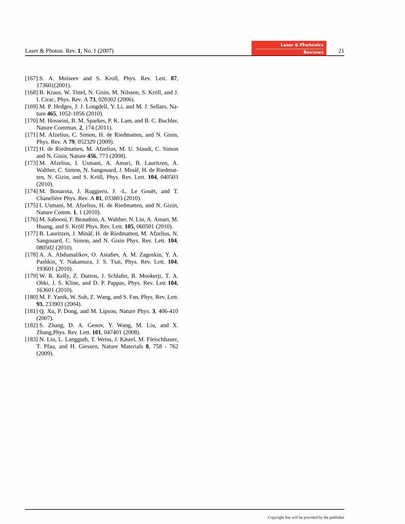
Laser & Photon. Rev.1, No. 1 (2007) 21
[167] S. A. Moiseev and S. Kroll, Phys. Rev. Lett.87,173601(2001).
[168] B. Kraus, W. Tittel, N. Gisin, M. Nilsson, S. Kroll, and J.I. Cirac, Phys. Rev. A73, 020302 (2006).
[169] M. P. Hedges, J. J. Longdell, Y. Li, and M. J. Sellars, Na-ture465, 1052-1056 (2010).
[170] M. Hosseini, B. M. Sparkes, P. K. Lam, and B. C. Buchler,Nature Commun.2, 174 (2011).
[171] M. Afzelius, C. Simon, H. de Riedmatten, and N. Gisin,Phys. Rev. A79, 052329 (2009).
[172] H. de Riedmatten, M. Afzelius, M. U. Staudt, C. Simonand N. Gisin, Nature456, 773 (2008).
[173] M. Afzelius, I. Usmani, A. Amari, B. Lauritzen, A.Walther, C. Simon, N. Sangouard, J. Minar, H. de Riedmat-ten, N. Gizin, and S. Kroll, Phys. Rev. Lett.104, 040503(2010).
[174] M. Bonarota, J. Ruggiero, J. -L. Le Gouet, and T.Chaneliere Phys. Rev. A81, 033803 (2010).
[175] I. Usmani, M. Afzelius, H. de Riedmatten, and N. Gizin,Nature Comm.1, 1 (2010).
[176] M. Sabooni, F. Beaudoin, A. Walther, N. Lin, A. Amari, M.Huang, and S. Kroll Phys. Rev. Lett.105, 060501 (2010).
[177] B. Lauritzen, J. Minar, H. de Riedmatten, M. Afzelius, N.Sangouard, C. Simon, and N. Gisin Phys. Rev. Lett.104,080502 (2010).
[178] A. A. Abdumalikov, O. Astafiev, A. M. Zagoskin, Y. A.Pashkin, Y. Nakamura, J. S. Tsai, Phys. Rev. Lett.104,193601 (2010).
[179] W. R. Kelly, Z. Dutton, J. Schlafer, B. Mookerji, T. A.Ohki, J. S. Kline, and D. P. Pappas, Phys. Rev. Lett104,163601 (2010).
[180] M. F. Yanik, W. Suh, Z. Wang, and S. Fan, Phys. Rev. Lett.93, 233903 (2004).
[181] Q. Xu, P. Dong, and M. Lipson, Nature Phys.3, 406-410(2007).
[182] S. Zhang, D. A. Genov, Y. Wang, M. Liu, and X.Zhang,Phys. Rev. Lett.101, 047401 (2008).
[183] N. Liu, L. Langguth, T. Weiss, J. Kastel, M. Fleischhauer,T. Pfau, and H. Giessen, Nature Materials8, 758 - 762(2009).
Copyright line will be provided by the publisher