ejector technology for efficient and cost effective flare ... · ejector technology for efficient...
TRANSCRIPT
2009 ZEECO, INC.
Ejector Technology for Efficient and Cost Effective Flare Gas Recovery
GPA-GCC 24th Annual Technical Conference,
Kuwait City, Kuwait, May 10-11, 2016
Trevor Leagas
Flare Gas Recovery Manager – Europe and Middle East Region
Zeeco, Inc
2009 ZEECO, INC.
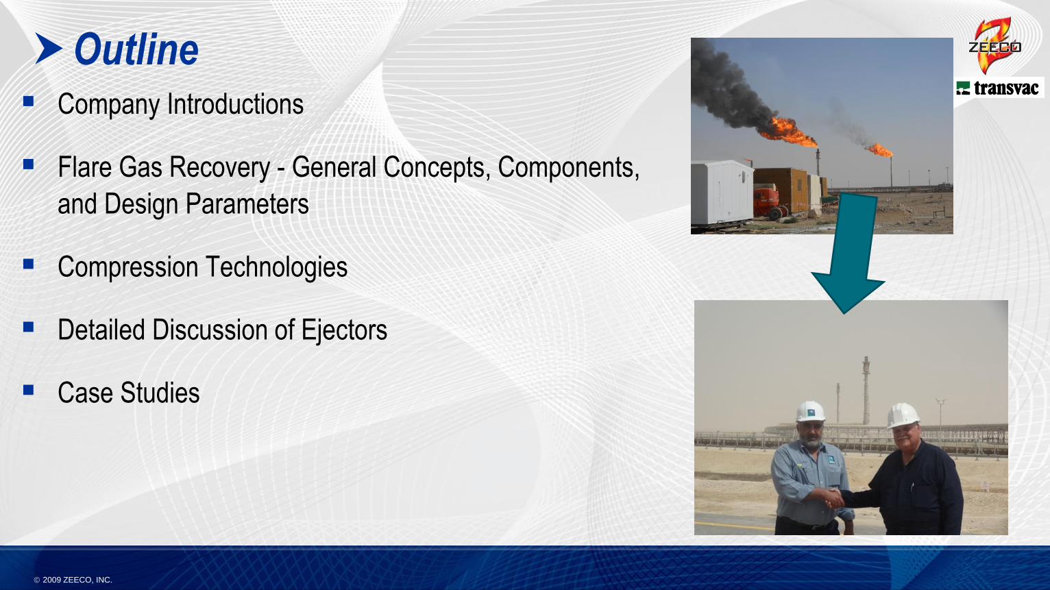
Outline Company Introductions
Flare Gas Recovery - General Concepts, Components,
and Design Parameters
Compression Technologies
Detailed Discussion of Ejectors
Case Studies
2009 ZEECO, INC.
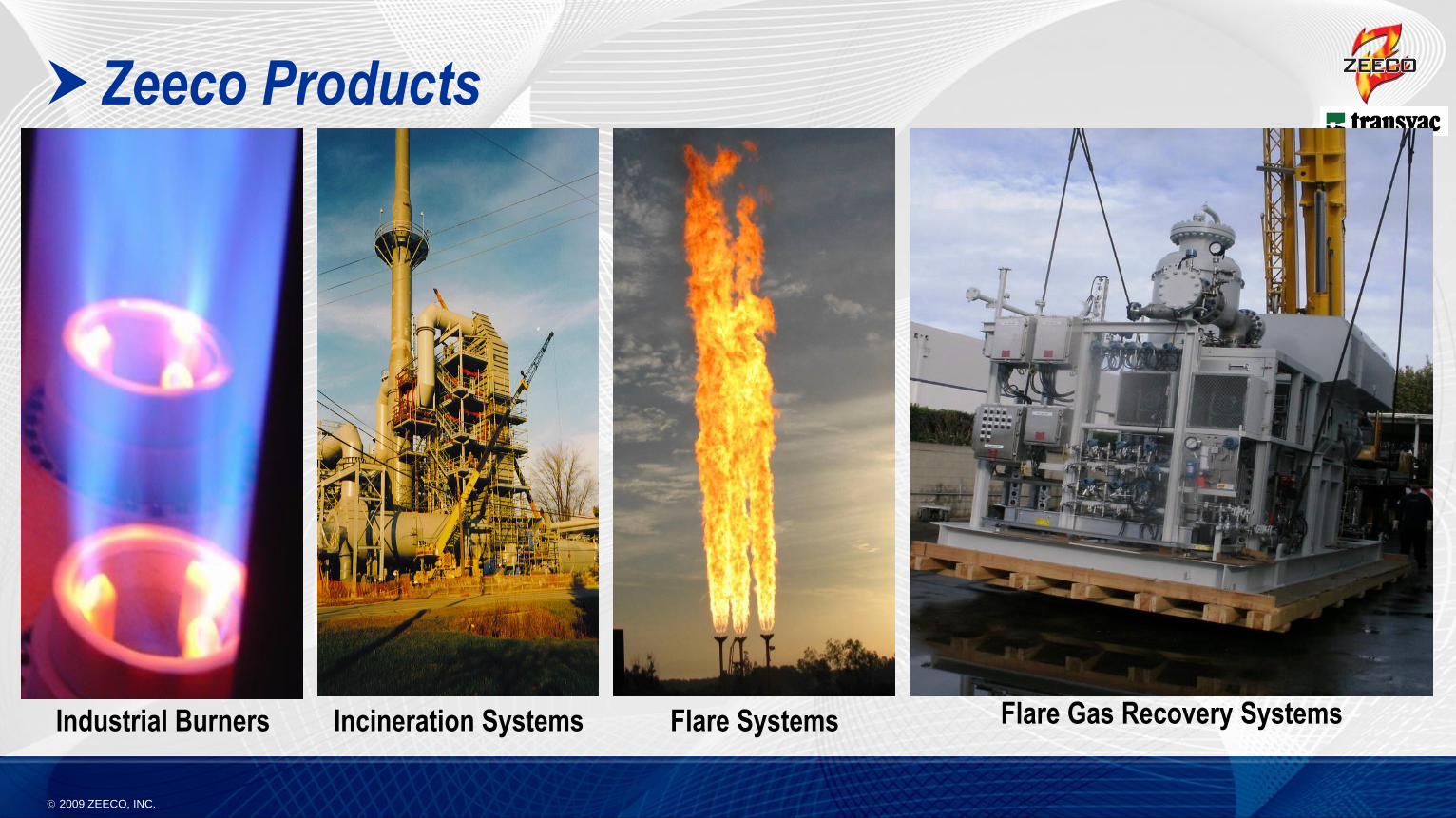
Zeeco Products
Industrial Burners Flare SystemsIncineration Systems Flare Gas Recovery Systems
2009 ZEECO, INC.
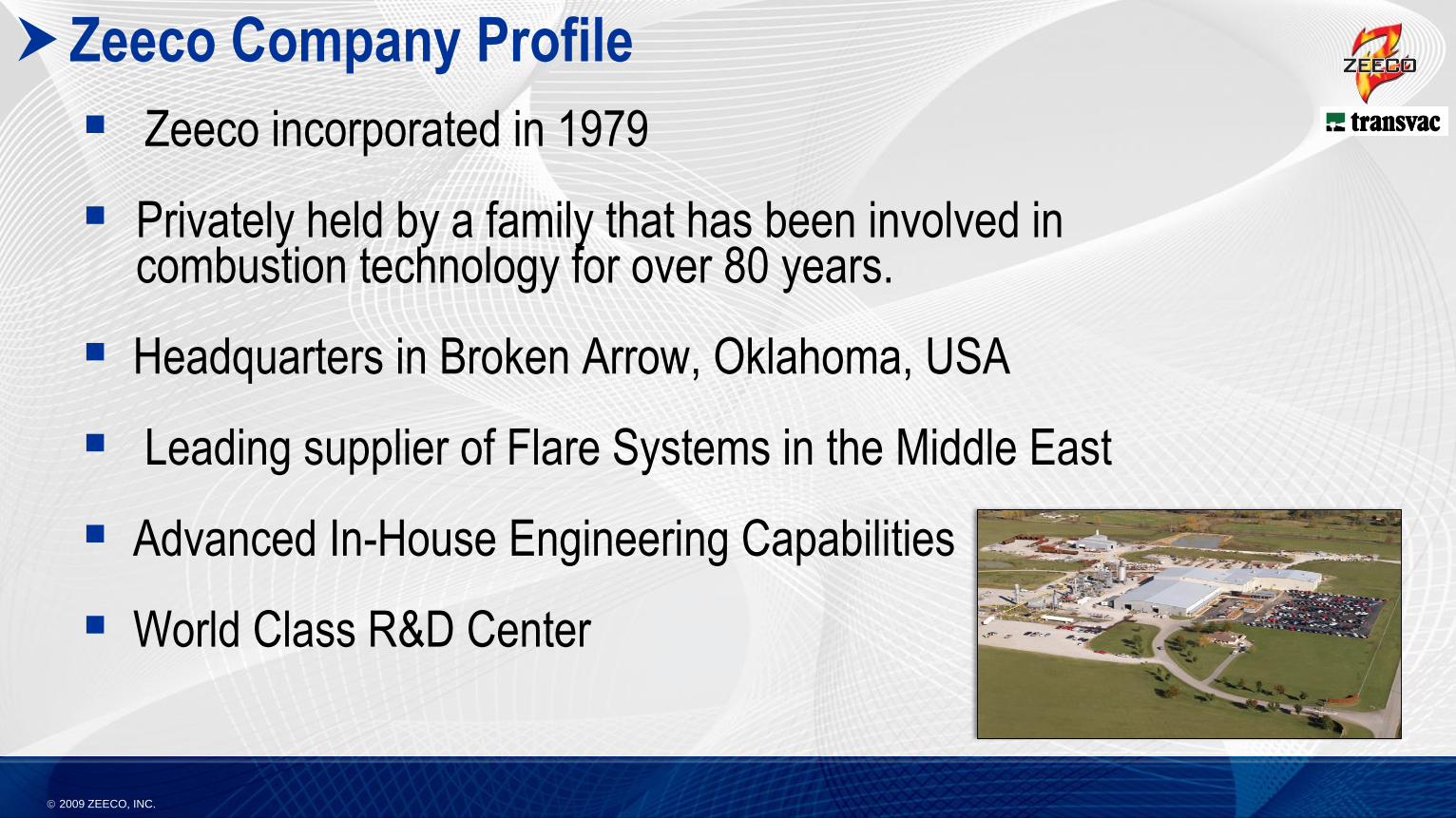
Zeeco Company Profile
Zeeco incorporated in 1979
Privately held by a family that has been involved in combustion technology for over 80 years.
Headquarters in Broken Arrow, Oklahoma, USA
Leading supplier of Flare Systems in the Middle East
Advanced In-House Engineering Capabilities
World Class R&D Center
2009 ZEECO, INC.
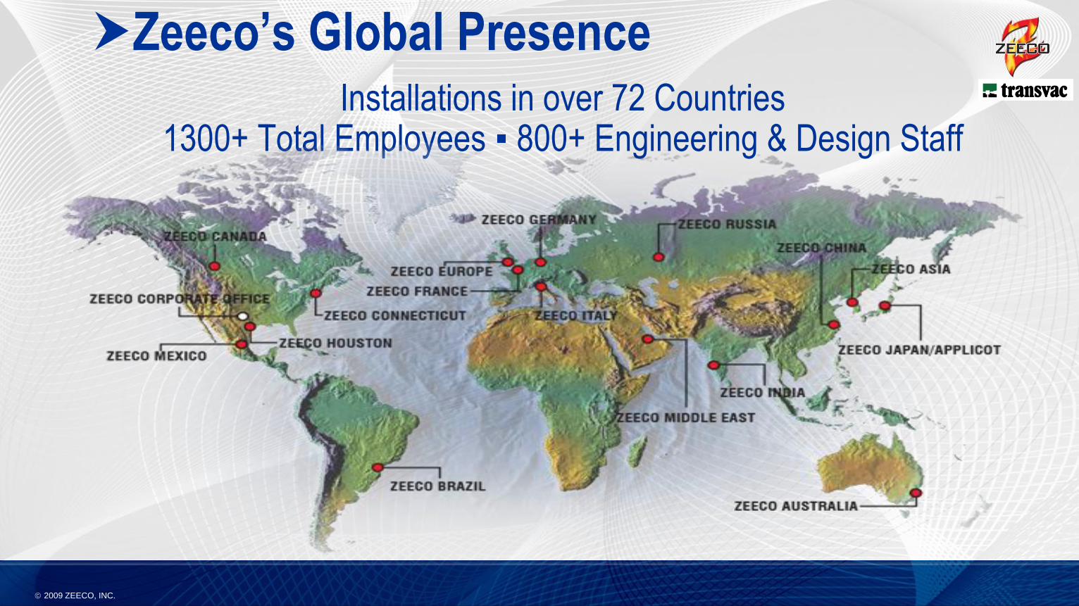
Zeeco’s Global PresenceInstallations in over 72 Countries
1300+ Total Employees ▪ 800+ Engineering & Design Staff
2009 ZEECO, INC.
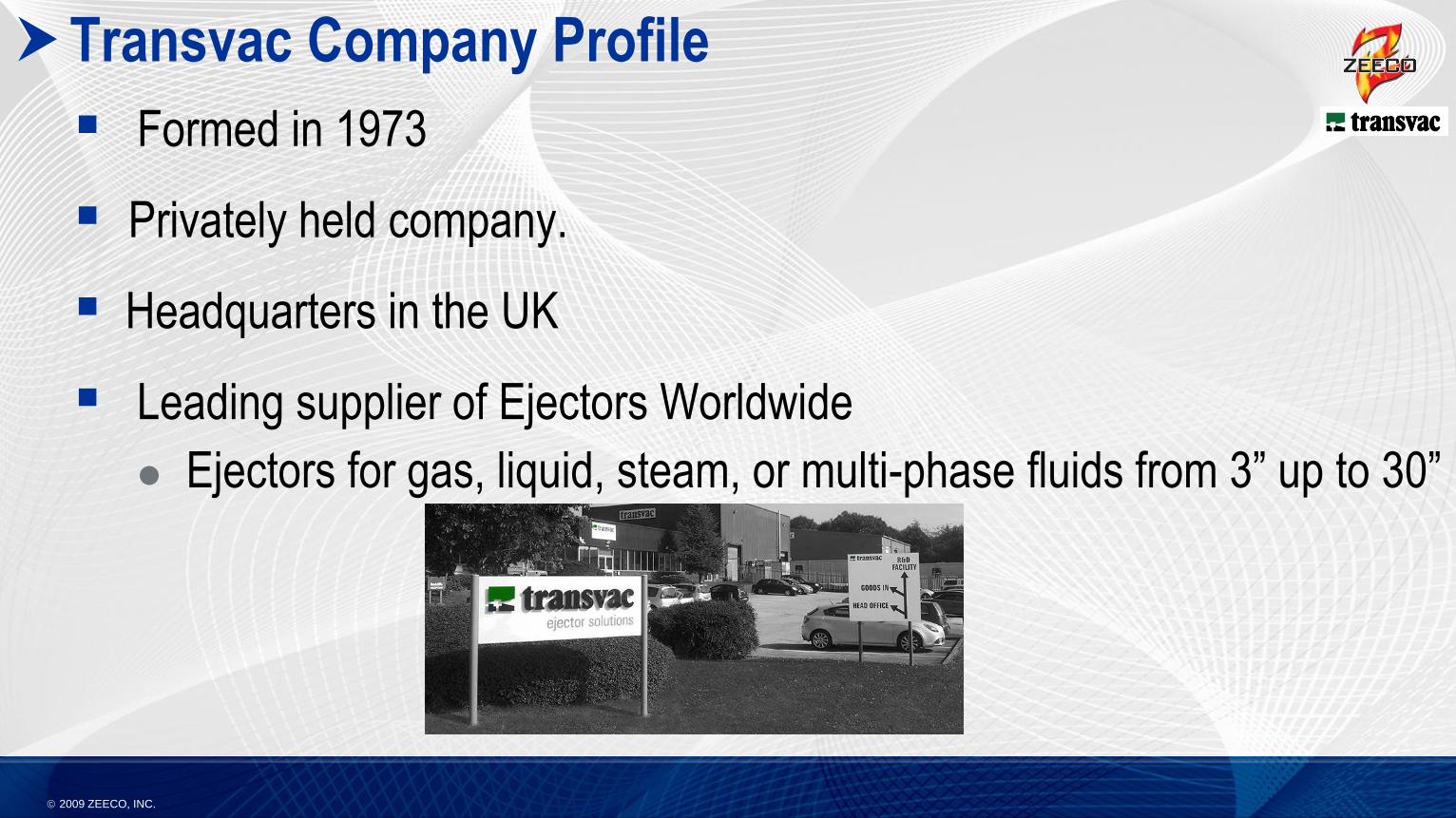
Transvac Company Profile
Formed in 1973
Privately held company.
Headquarters in the UK
Leading supplier of Ejectors Worldwide
Ejectors for gas, liquid, steam, or multi-phase fluids from 3” up to 30”
2009 ZEECO, INC.
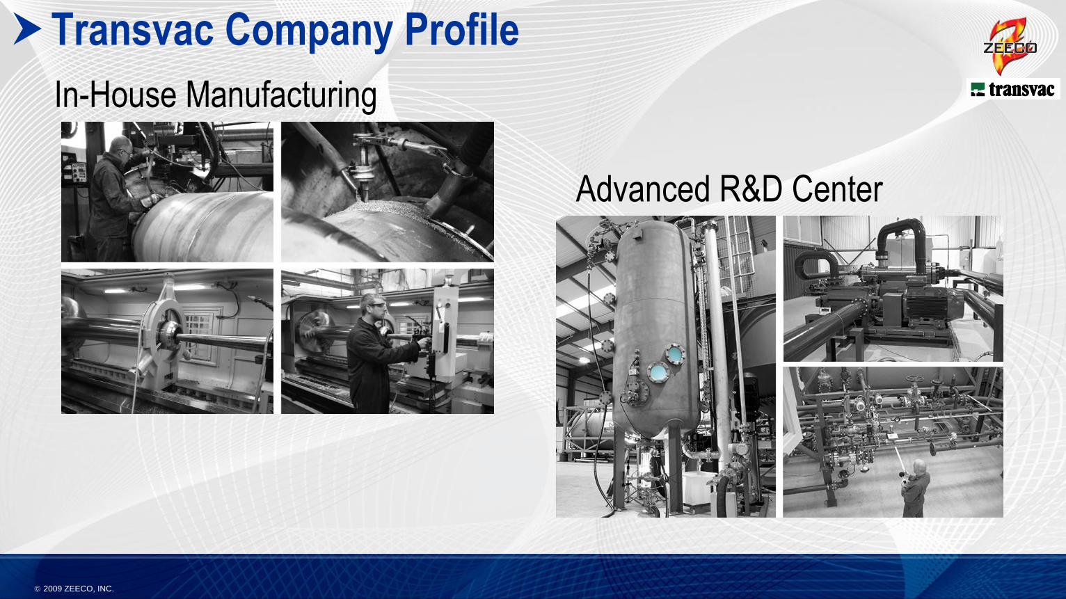
Transvac Company Profile
In-House Manufacturing
Advanced R&D Center
2009 ZEECO, INC.
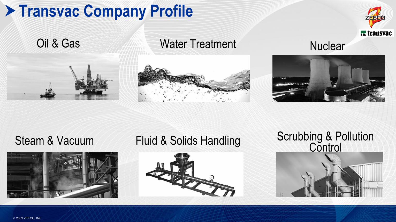
Transvac Company Profile
Oil & Gas Water Treatment
Steam & Vacuum Fluid & Solids Handling
Nuclear
Scrubbing & Pollution Control
2009 ZEECO, INC.
Flare Gas Recovery - General Concepts,
Components, and Design Parameters
2009 ZEECO, INC.
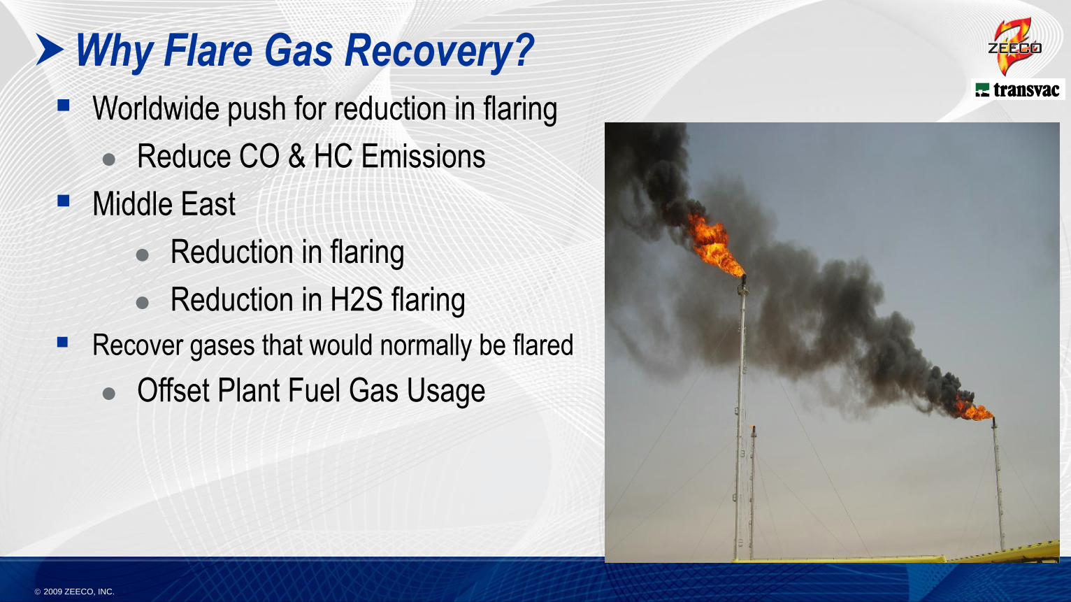
Why Flare Gas Recovery?
Worldwide push for reduction in flaring
Reduce CO & HC Emissions
Middle East
Reduction in flaring
Reduction in H2S flaring
Recover gases that would normally be flared
Offset Plant Fuel Gas Usage
2009 ZEECO, INC.
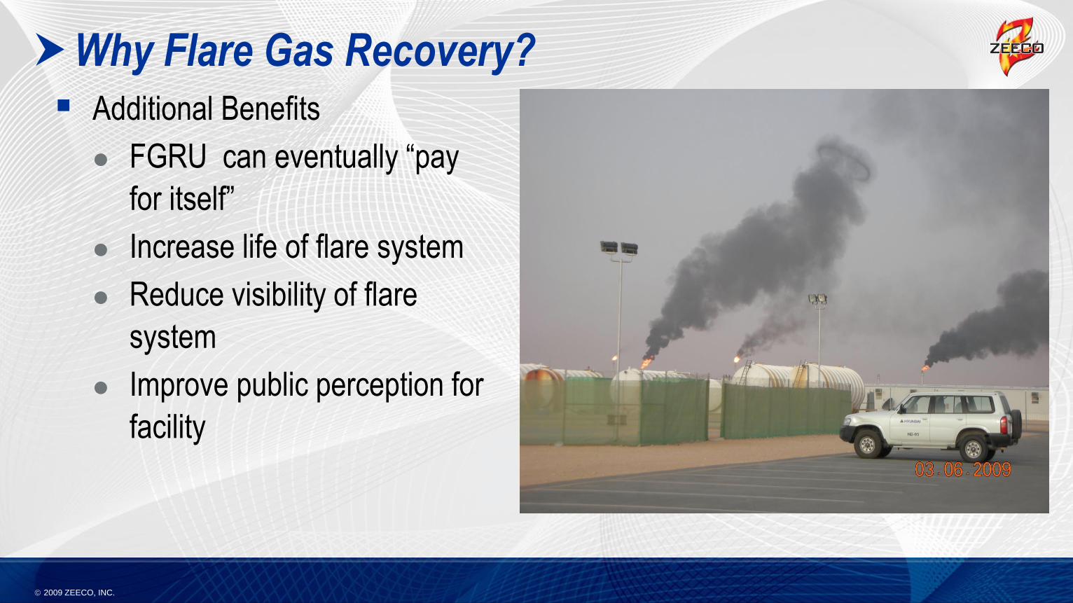
Why Flare Gas Recovery?
Additional Benefits
FGRU can eventually “pay
for itself”
Increase life of flare system
Reduce visibility of flare
system
Improve public perception for
facility
2009 ZEECO, INC.
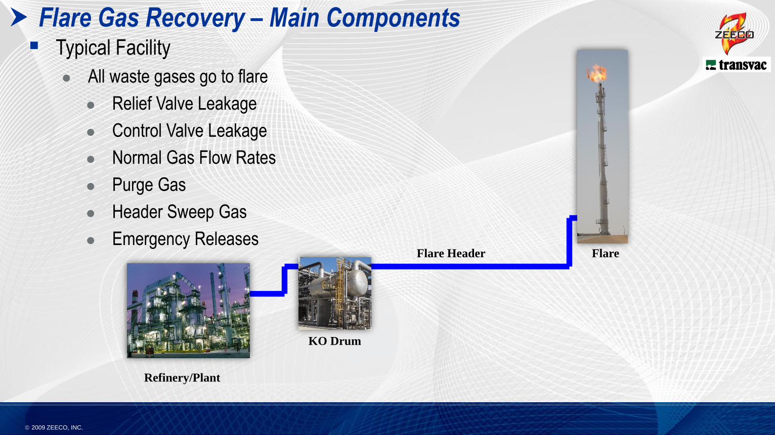
Flare Gas Recovery – Main Components Typical Facility
All waste gases go to flare
Relief Valve Leakage
Control Valve Leakage
Normal Gas Flow Rates
Purge Gas
Header Sweep Gas
Emergency ReleasesFlare Header Flare
KO Drum
Refinery/Plant
2009 ZEECO, INC.
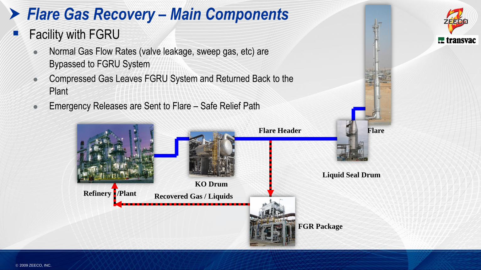
Facility with FGRU
Normal Gas Flow Rates (valve leakage, sweep gas, etc) are
Bypassed to FGRU System
Compressed Gas Leaves FGRU System and Returned Back to the
Plant
Emergency Releases are Sent to Flare – Safe Relief Path
Recovered Gas / Liquids
Liquid Seal Drum
Flare Header Flare
KO Drum
Flare Gas Recovery – Main Components
Refinery /Plant
FGR Package
2009 ZEECO, INC.
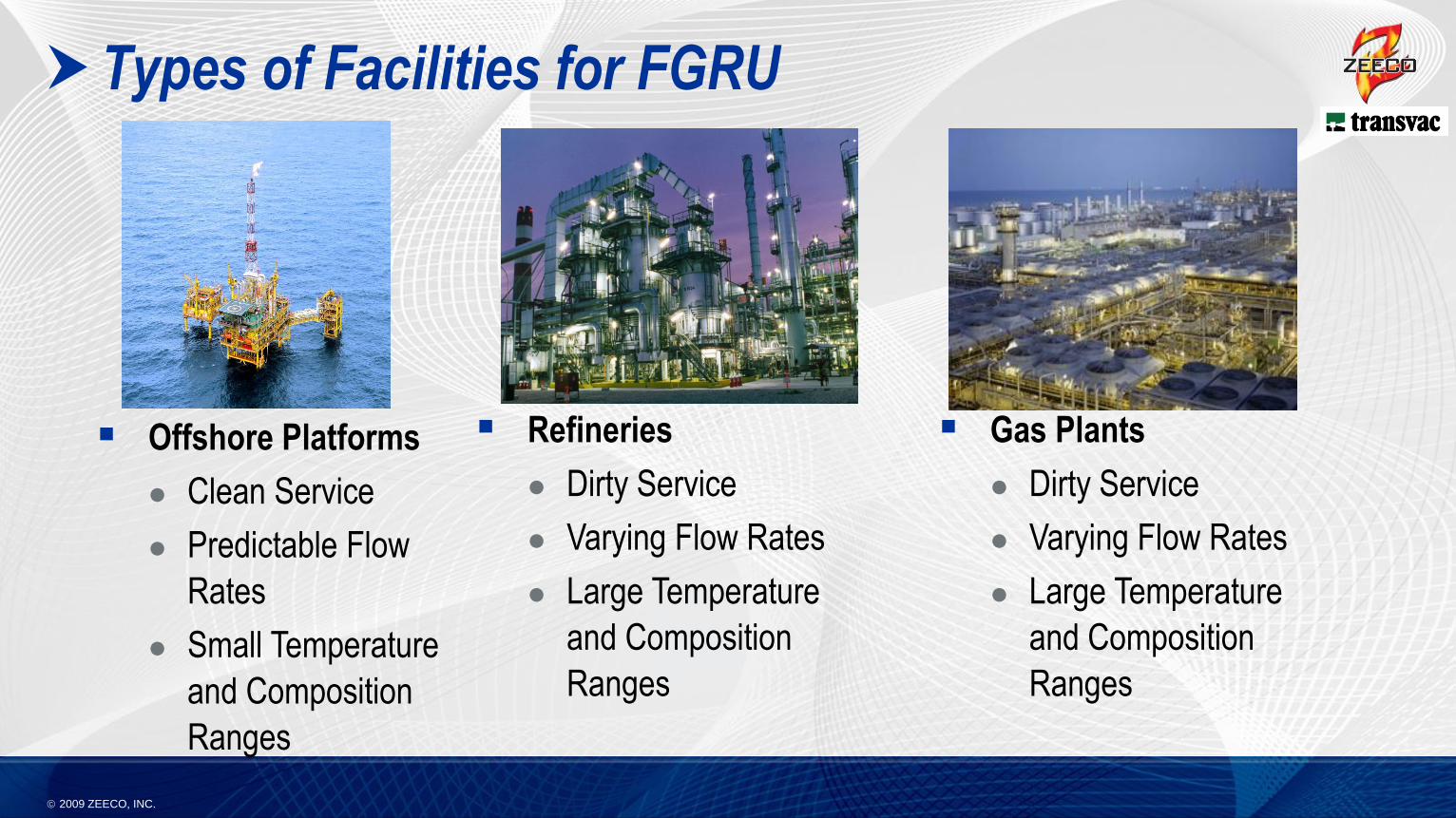
Types of Facilities for FGRU
Offshore Platforms
Clean Service
Predictable Flow
Rates
Small Temperature
and Composition
Ranges
Refineries
Dirty Service
Varying Flow Rates
Large Temperature
and Composition
Ranges
Gas Plants
Dirty Service
Varying Flow Rates
Large Temperature
and Composition
Ranges
2009 ZEECO, INC.
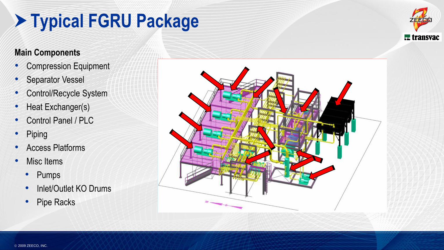
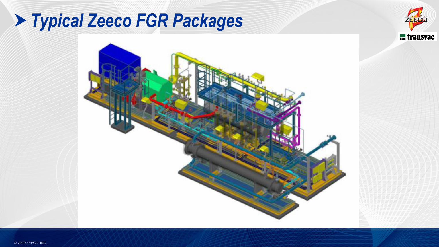
Typical FGRU Package
Main Components
• Compression Equipment
• Separator Vessel
• Control/Recycle System
• Heat Exchanger(s)
• Control Panel / PLC
• Piping
• Access Platforms
• Misc Items
• Pumps
• Inlet/Outlet KO Drums
• Pipe Racks
2009 ZEECO, INC.
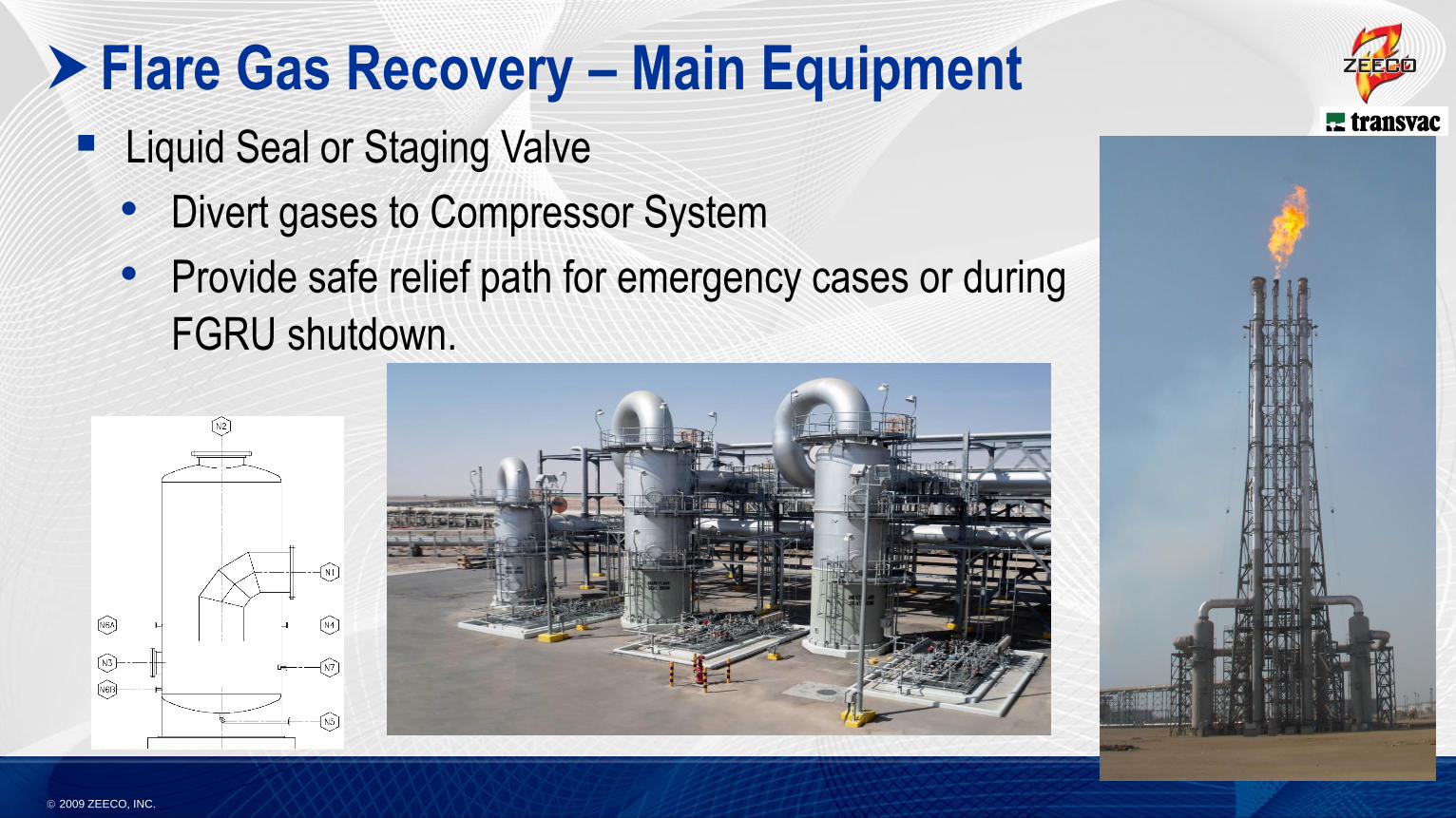
Flare Gas Recovery – Main Equipment
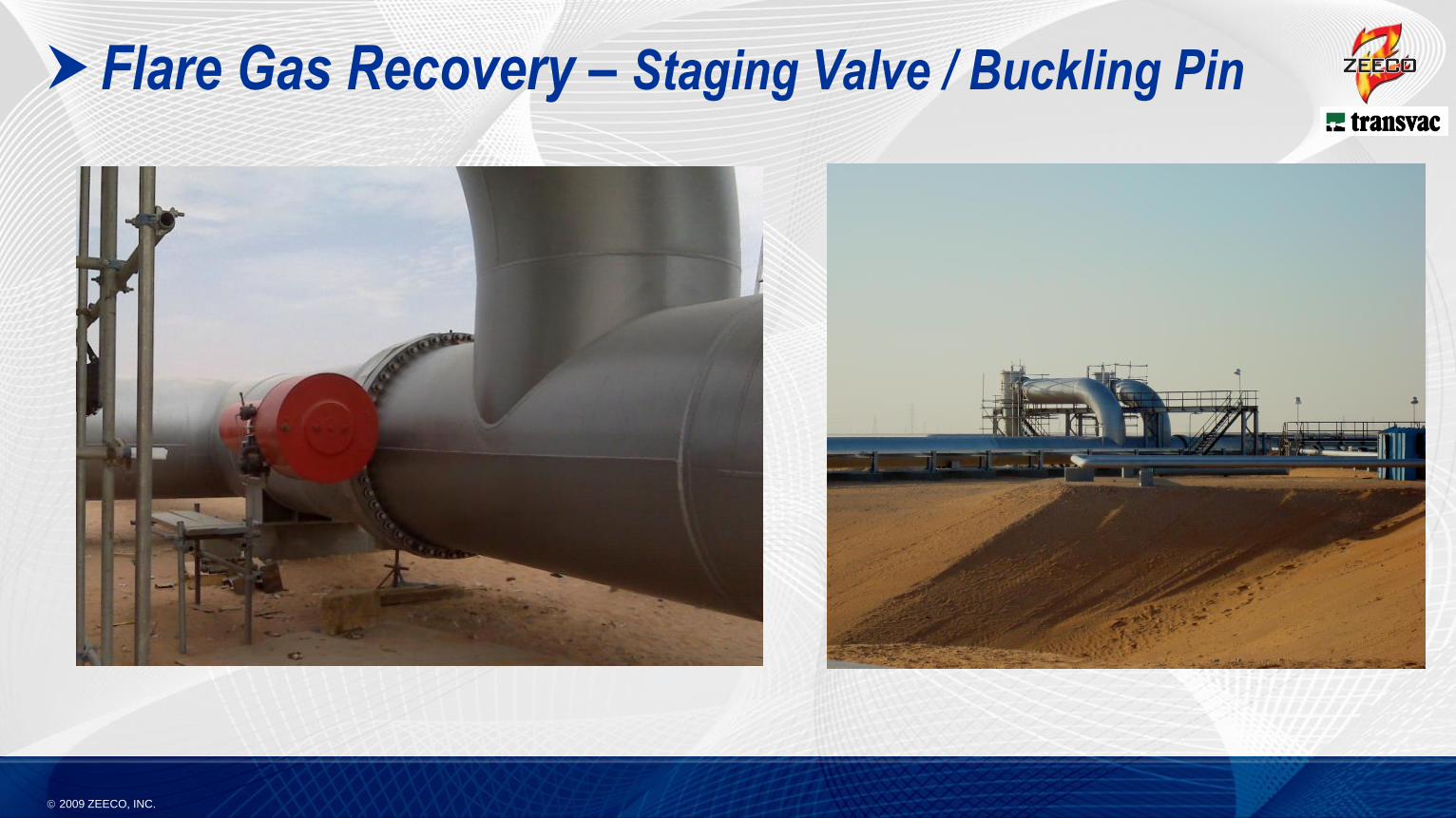
Liquid Seal or Staging Valve
• Divert gases to Compressor System
• Provide safe relief path for emergency cases or during
FGRU shutdown.
2009 ZEECO, INC.
Flare Gas Recovery – Liquid Seal Drum
2009 ZEECO, INC.
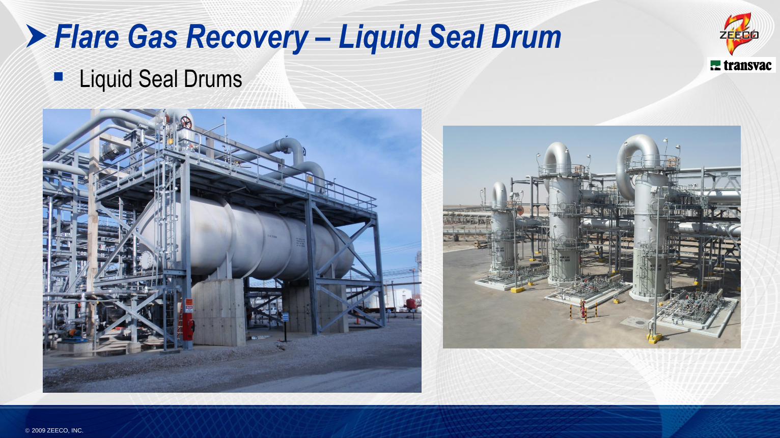
Flare Gas Recovery – Liquid Seal Drum
Liquid Seal Drums
2009 ZEECO, INC.
Flare Gas Recovery – Staging Valve / Buckling Pin
2009 ZEECO, INC.
System Capacity
System Suction and Discharge Pressure
Flare Gas Composition
Gas Temperatures
Ambient Conditions / Jobsite Location
Available Utilities
Location of FGRU
How many flares will be tied into the FGRU?
Selection of proper equipment for diverting gas to FGRU
system and providing safe relief to flare.
Design Parameters for FGRU
2009 ZEECO, INC.
Availability of Water
Cost of electricity.
Value of Recovered Gases
Required System Turndown
Frequency of Plant Shutdowns
Required Service Life of Equipment
Redundancy in Design
Access of equipment for maintenance
Control system logic (local PLC or DCS)?
Shaft Seal Types
Customer Specifications
Approved Vendor Lists
Extent of Modularization
Required Delivery Date
Design Parameters for FGRU
2009 ZEECO, INC.
Special Design Considerations for Hot, Desert Regions
Availability and Processing of Water
• Liquid seal vessels.
• Liquid Ring Compressors and Liquid Ejectors
• Water Cooled vs Air Cooled Heat Exchangers
High Ambient Temperatures
• Evaporation Rates
• Motor Selection
• Protection of Controls and Instruments
2009 ZEECO, INC.
Special Design Considerations for Hot, Desert Regions
Sand Storms and High Sand Content
• Protection of Instruments
• Close Tolerances in Compressors and Pumps
Sour Flare Gases
• Contamination of Oil
• Contamination of Water
• Special Materials of Construction
• Protection of Personnel
2009 ZEECO, INC.
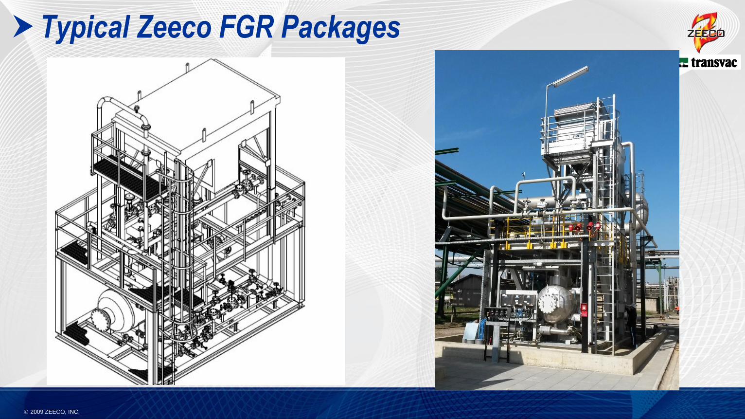
Typical Zeeco FGR Packages
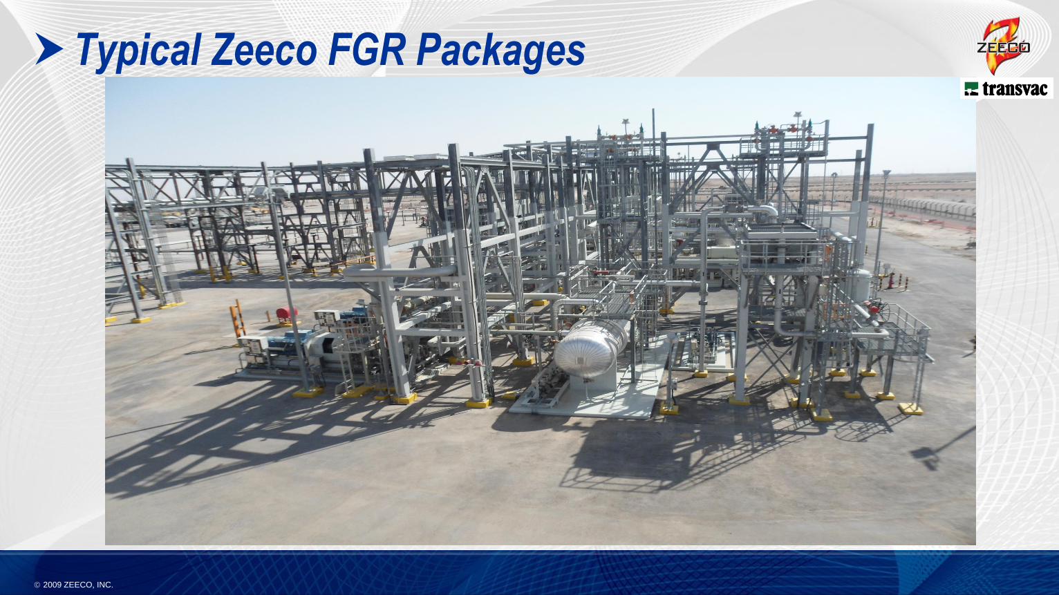
2009 ZEECO, INC.
Typical Zeeco FGR Packages
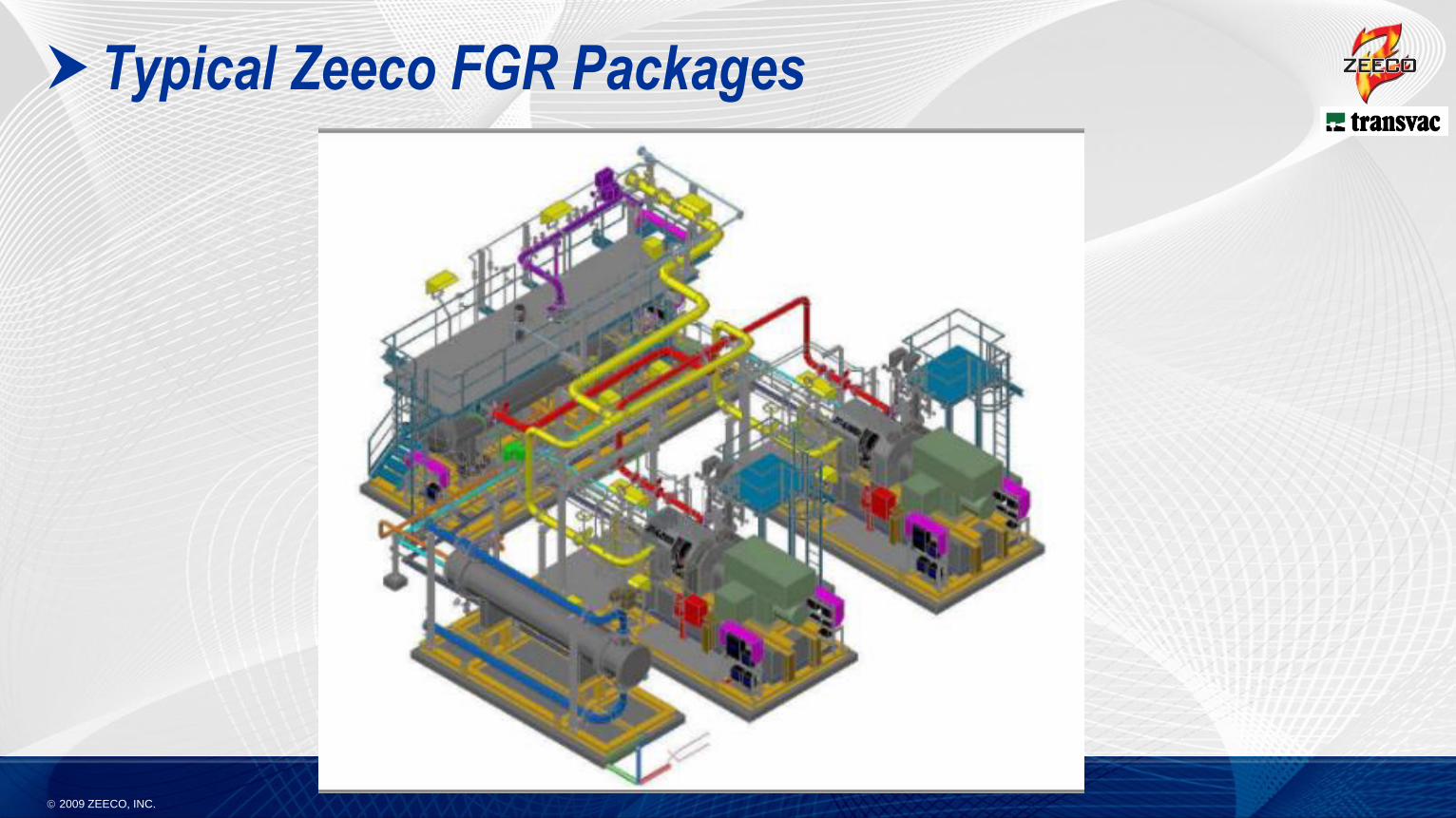
2009 ZEECO, INC.
Typical Zeeco FGR Packages
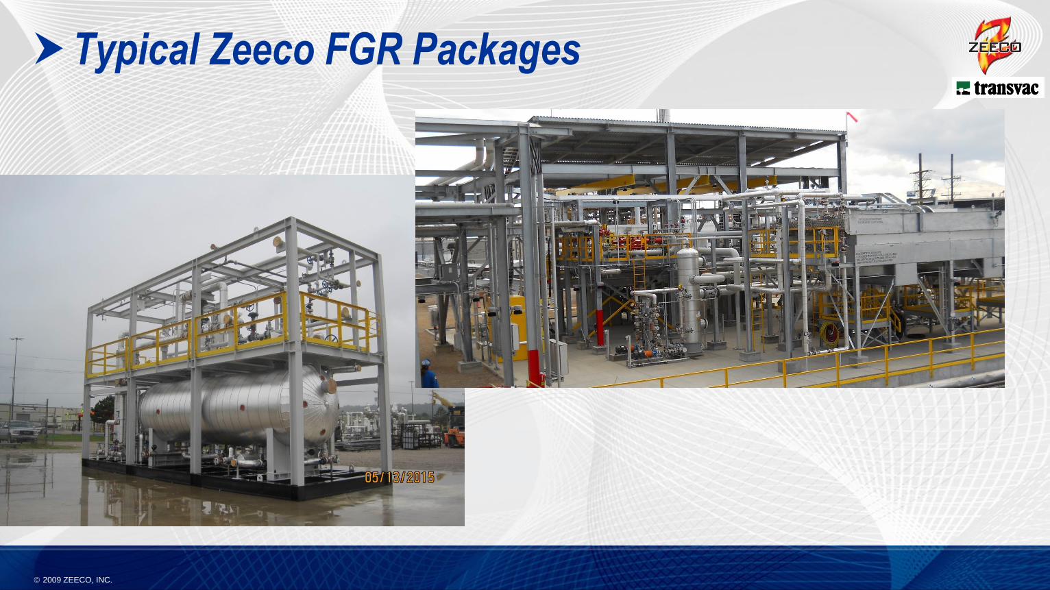
2009 ZEECO, INC.
Typical Zeeco FGR Packages
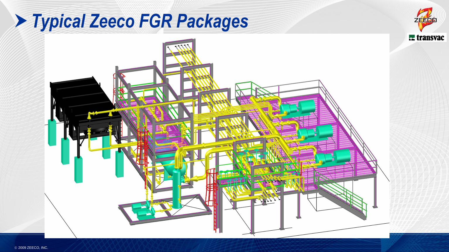
2009 ZEECO, INC.
Typical Zeeco FGR Packages
2009 ZEECO, INC.
Typical Zeeco FGR Packages
2009 ZEECO, INC.
Proper System Design – Safety and Operation Concerns
The concept of Flare Gas Recovery seems simple;
however, the flare system is the single most important
piece of safety equipment in the entire facility. Whoever
is working on design changes involving the flare
system must COMPLETELY understand the
implications of changes and the dangers / risks
associated with these changes.
2009 ZEECO, INC.
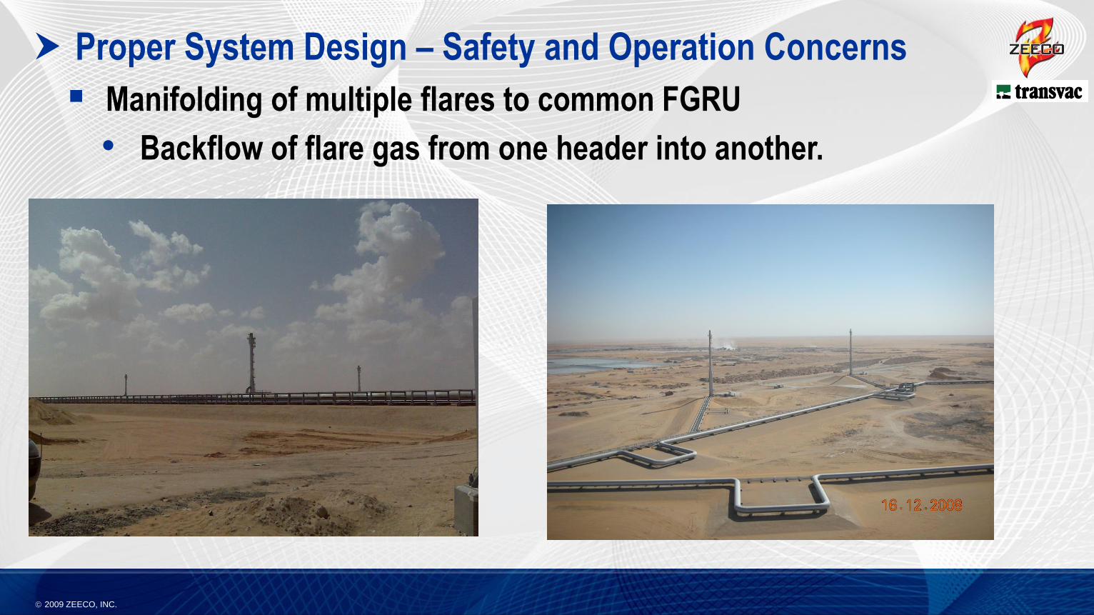
Proper System Design – Safety and Operation Concerns
Manifolding of multiple flares to common FGRU
• Backflow of flare gas from one header into another.
2009 ZEECO, INC.
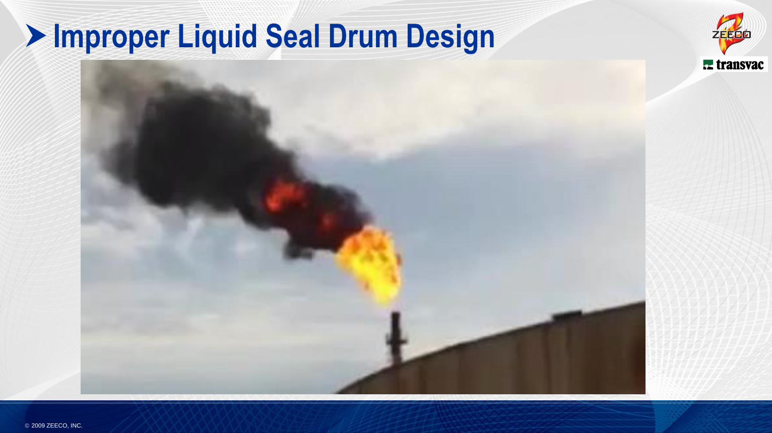
Improper Liquid Seal Drum Design
2009 ZEECO, INC.
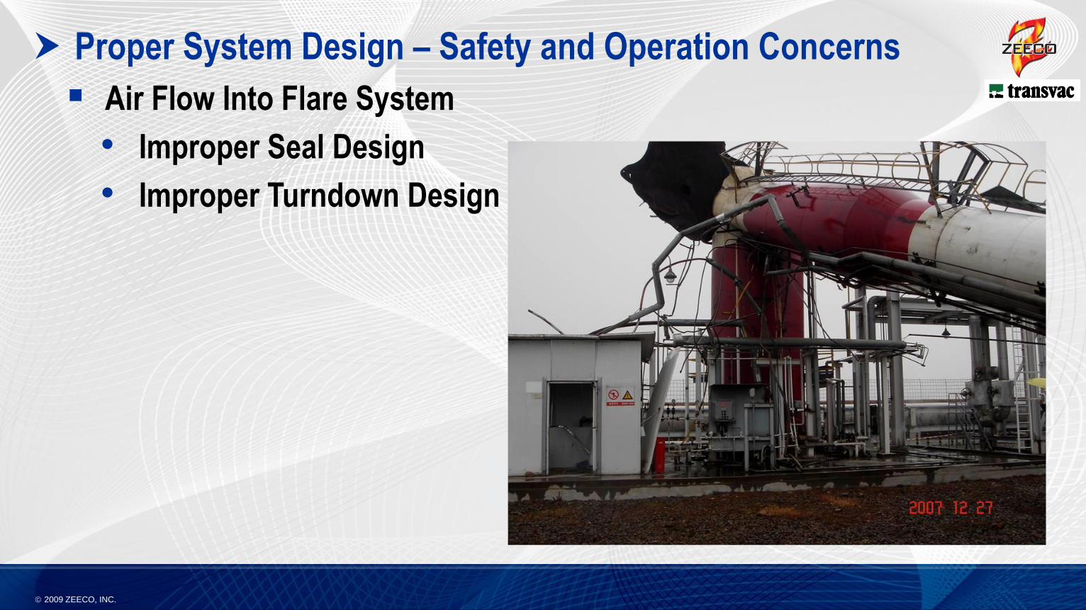
Proper System Design – Safety and Operation Concerns
Air Flow Into Flare System
• Improper Seal Design
• Improper Turndown Design
2009 ZEECO, INC.
Compression Technologies
2009 ZEECO, INC.
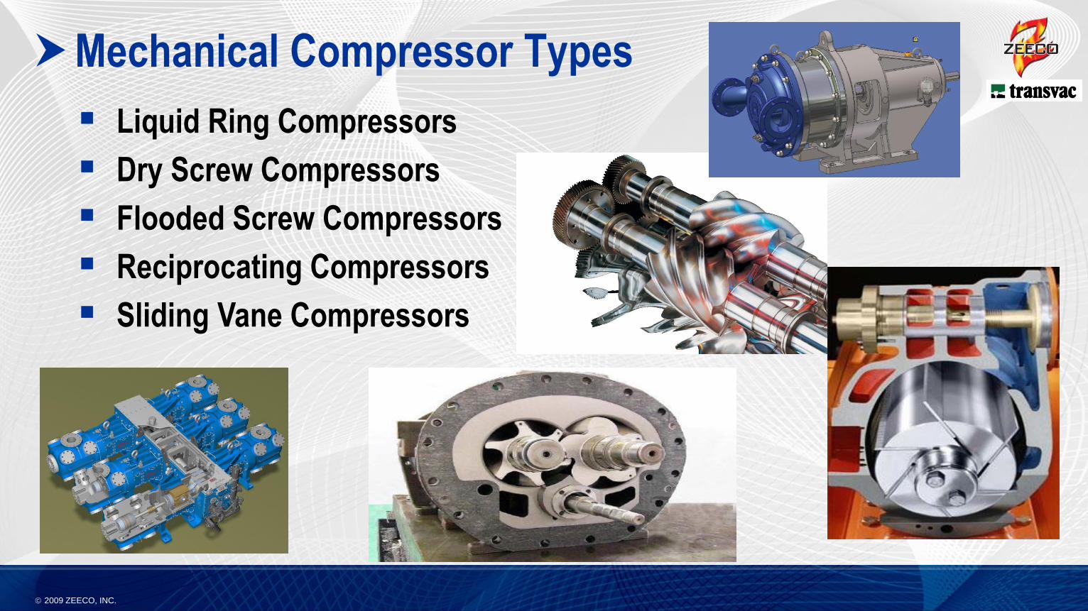
Mechanical Compressor Types
Liquid Ring Compressors
Dry Screw Compressors
Flooded Screw Compressors
Reciprocating Compressors
Sliding Vane Compressors
2009 ZEECO, INC.
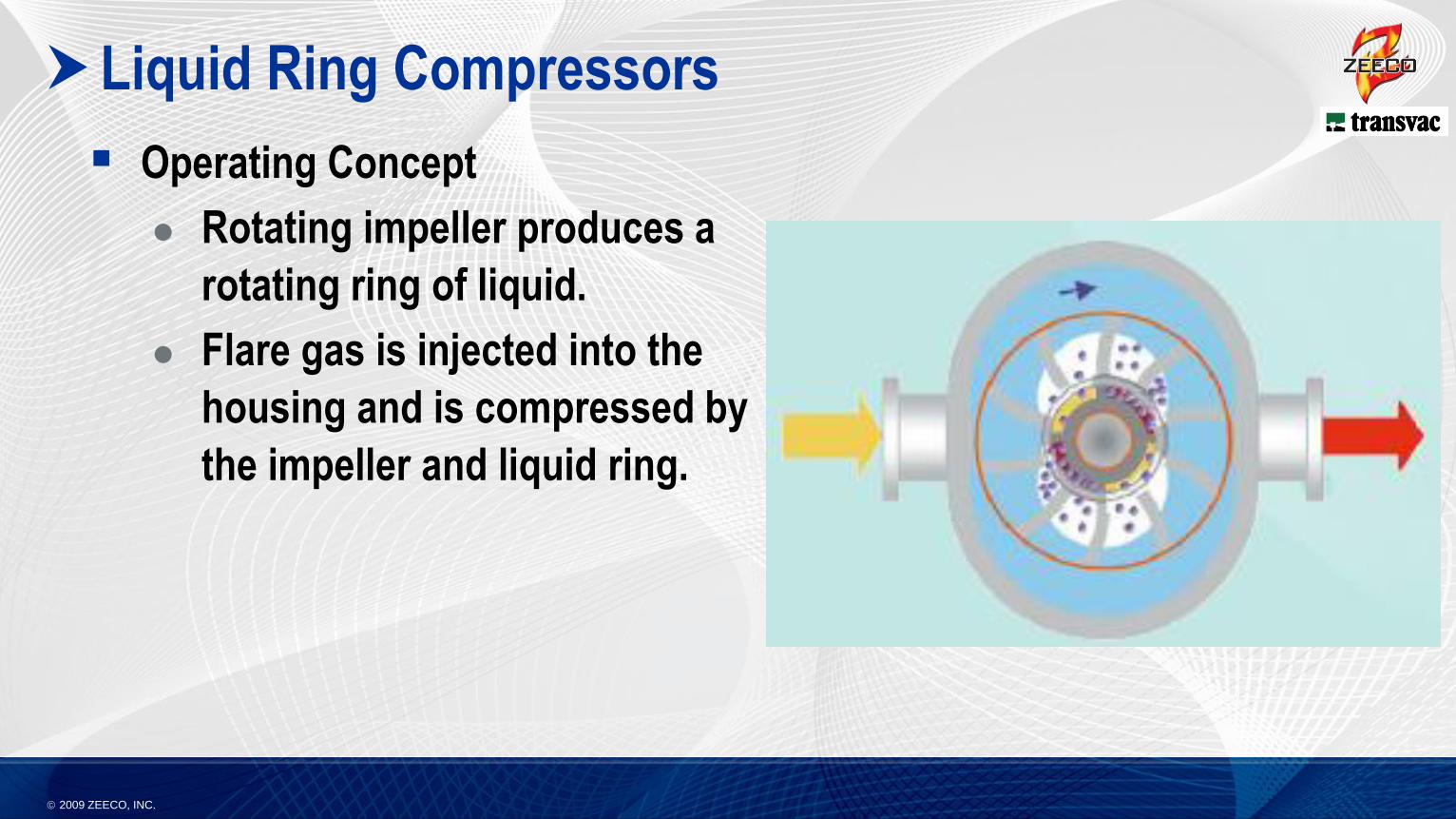
Liquid Ring Compressors
Operating Concept
Rotating impeller produces a
rotating ring of liquid.
Flare gas is injected into the
housing and is compressed by
the impeller and liquid ring.
2009 ZEECO, INC.
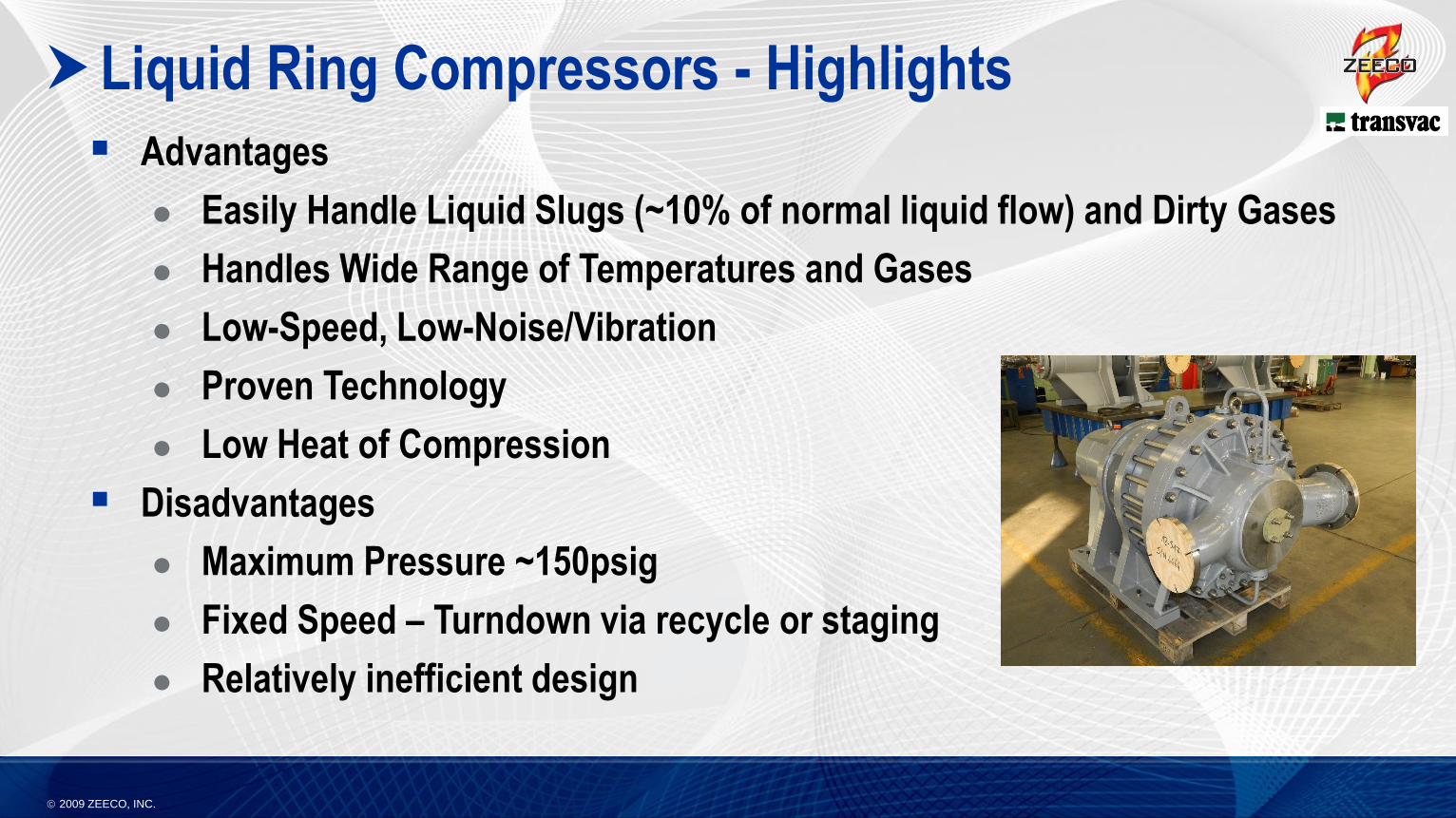
Liquid Ring Compressors - Highlights
Advantages
Easily Handle Liquid Slugs (~10% of normal liquid flow) and Dirty Gases
Handles Wide Range of Temperatures and Gases
Low-Speed, Low-Noise/Vibration
Proven Technology
Low Heat of Compression
Disadvantages
Maximum Pressure ~150psig
Fixed Speed – Turndown via recycle or staging
Relatively inefficient design
2009 ZEECO, INC.
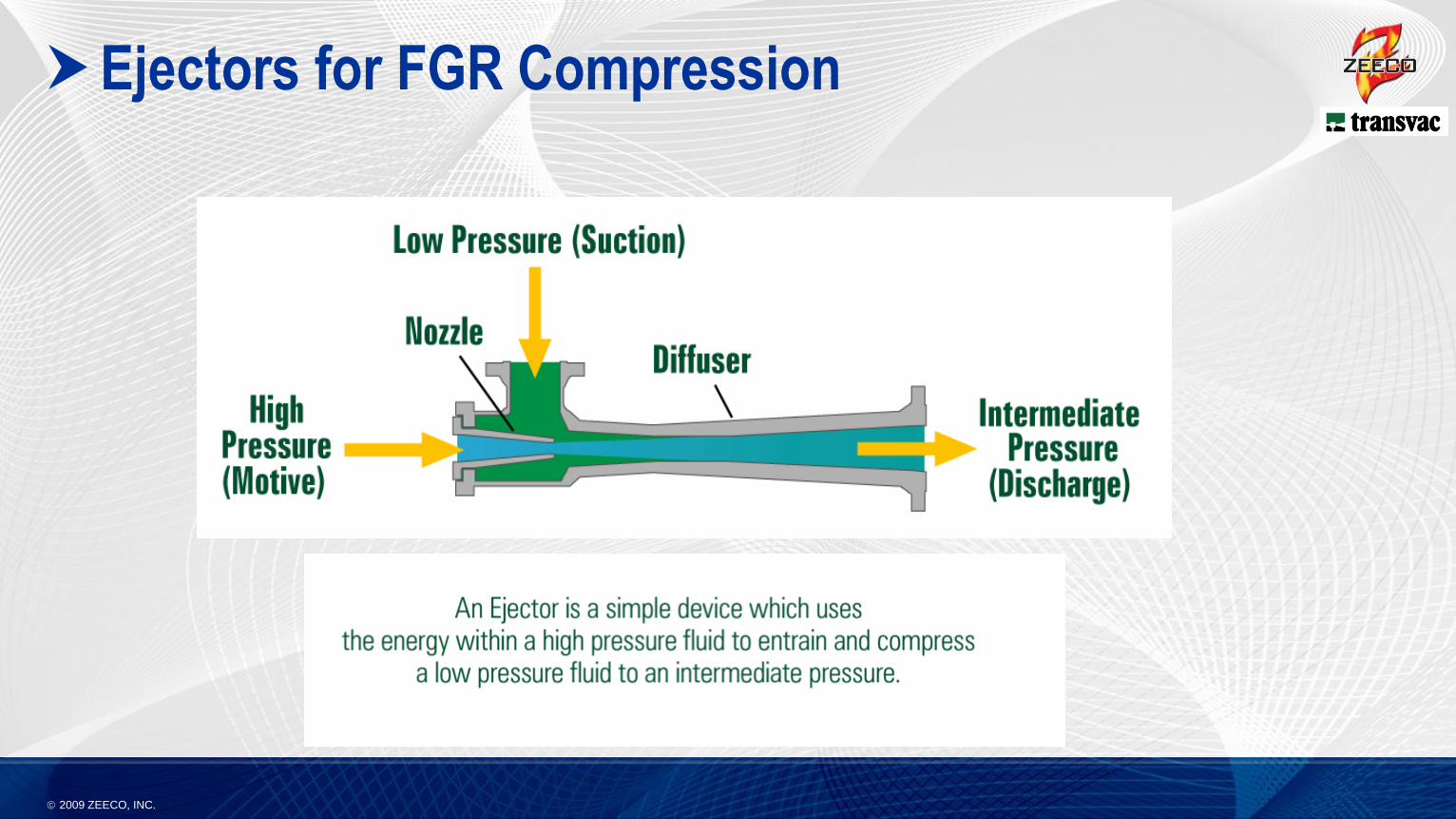
Ejectors for FGR Compression
2009 ZEECO, INC.
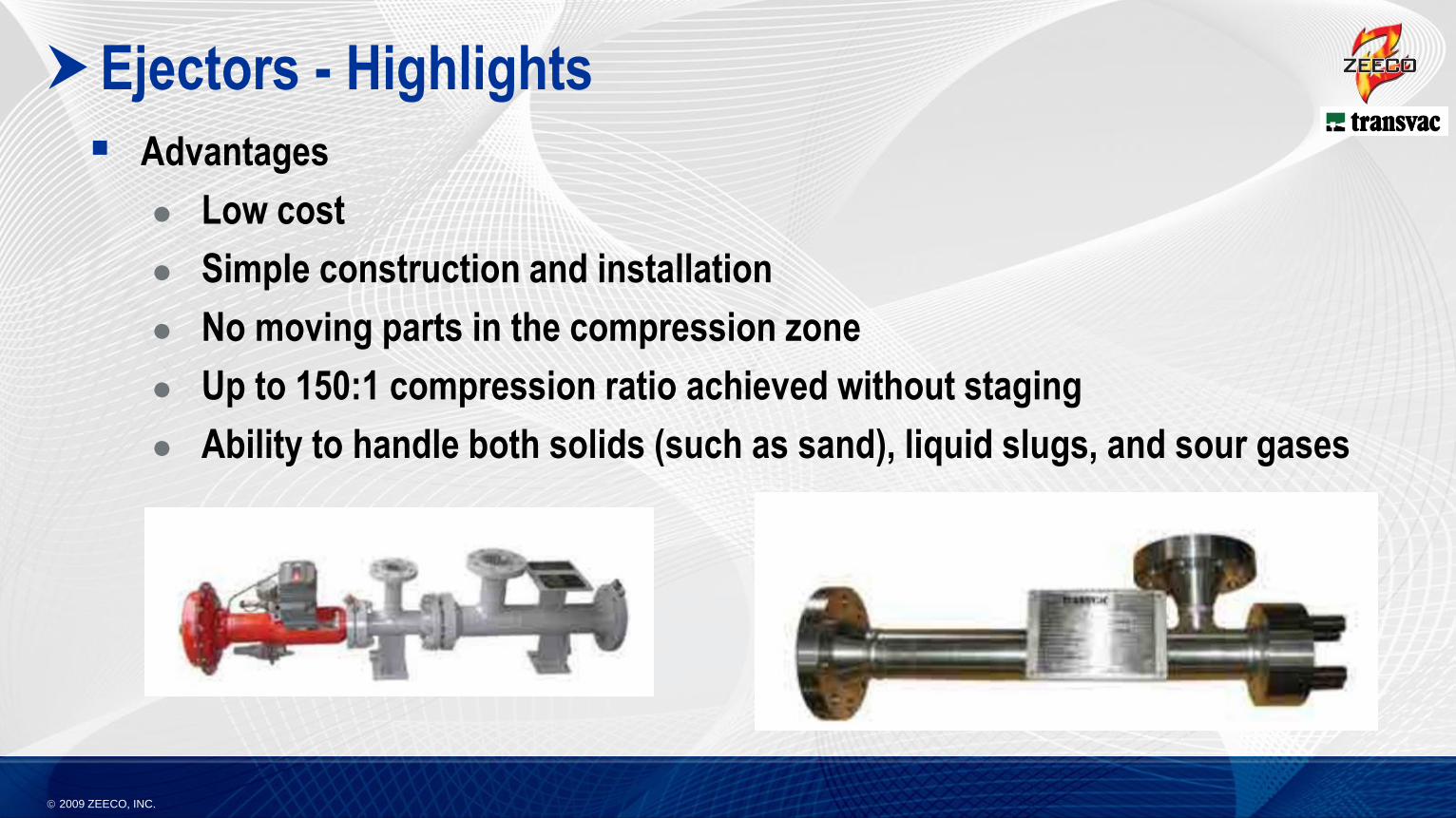
Ejectors - Highlights
Advantages
Low cost
Simple construction and installation
No moving parts in the compression zone
Up to 150:1 compression ratio achieved without staging
Ability to handle both solids (such as sand), liquid slugs, and sour gases
2009 ZEECO, INC.
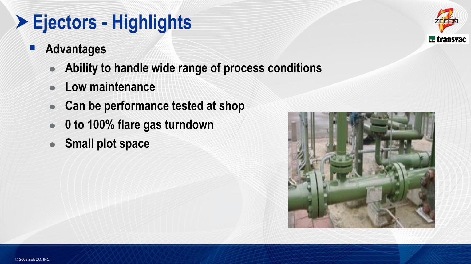
Ejectors - Highlights
Advantages
Ability to handle wide range of process conditions
Low maintenance
Can be performance tested at shop
0 to 100% flare gas turndown
Small plot space
2009 ZEECO, INC.
Ejectors - Highlights
Disadvantages
Low volumetric efficiency compared to some compression technologies.
High motive fluid flowrate
High motive pressure required
2009 ZEECO, INC.
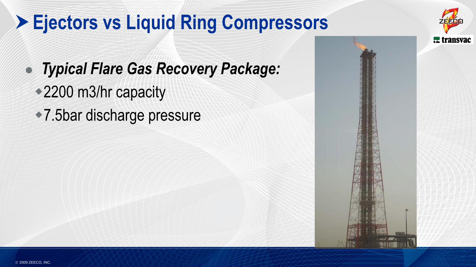
Ejectors vs Liquid Ring Compressors
Typical Flare Gas Recovery Package:
2200 m3/hr capacity
7.5bar discharge pressure
2009 ZEECO, INC.
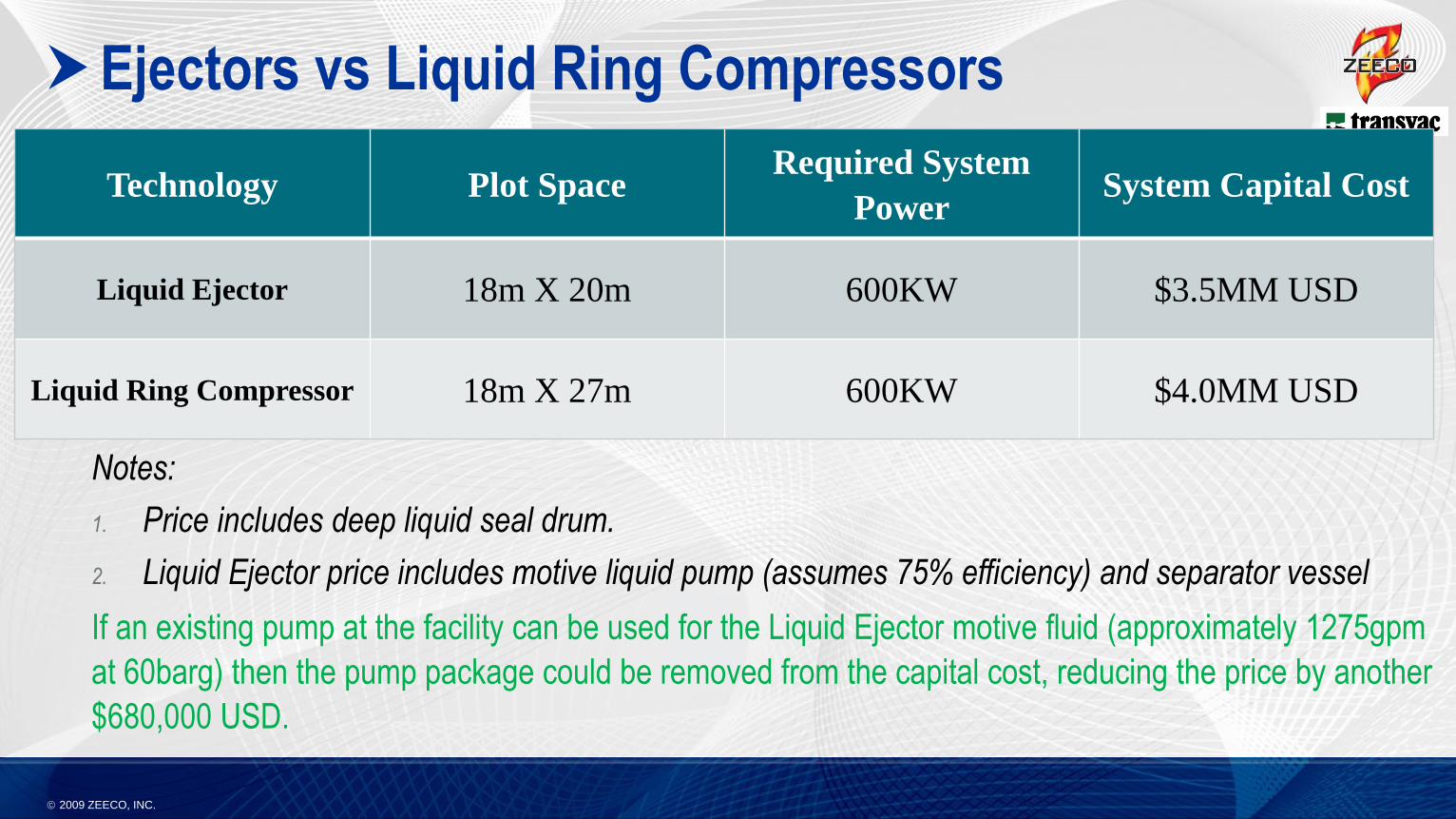
Ejectors vs Liquid Ring Compressors
Technology Plot SpaceRequired System
PowerSystem Capital Cost
Liquid Ejector 18m X 20m 600KW $3.5MM USD
Liquid Ring Compressor 18m X 27m 600KW $4.0MM USD
Notes:
1. Price includes deep liquid seal drum.
2. Liquid Ejector price includes motive liquid pump (assumes 75% efficiency) and separator vessel
If an existing pump at the facility can be used for the Liquid Ejector motive fluid (approximately 1275gpm
at 60barg) then the pump package could be removed from the capital cost, reducing the price by another
$680,000 USD.

2009 ZEECO, INC.
Detailed Discussion of Ejectors
2009 ZEECO, INC.
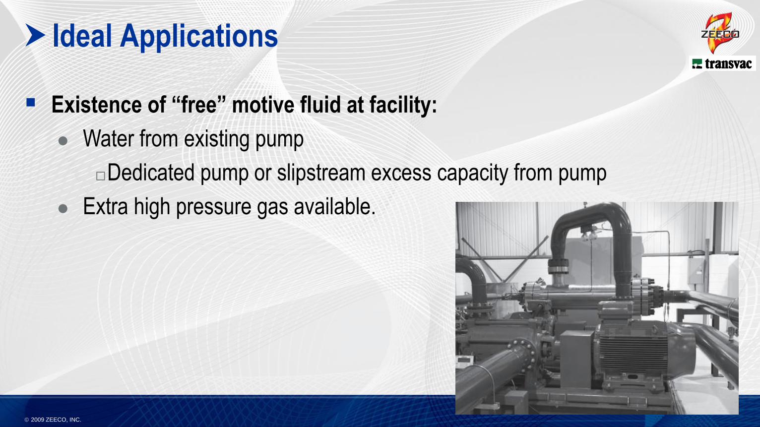
Ideal Applications
Existence of “free” motive fluid at facility:
Water from existing pump
Dedicated pump or slipstream excess capacity from pump
Extra high pressure gas available.
2009 ZEECO, INC.
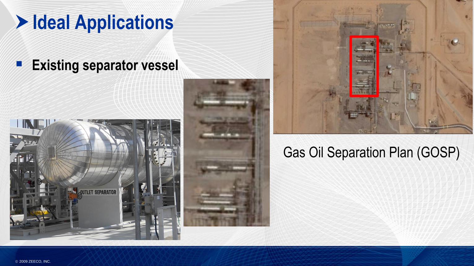
Ideal Applications
Existing separator vessel
Gas Oil Separation Plan (GOSP)
2009 ZEECO, INC.
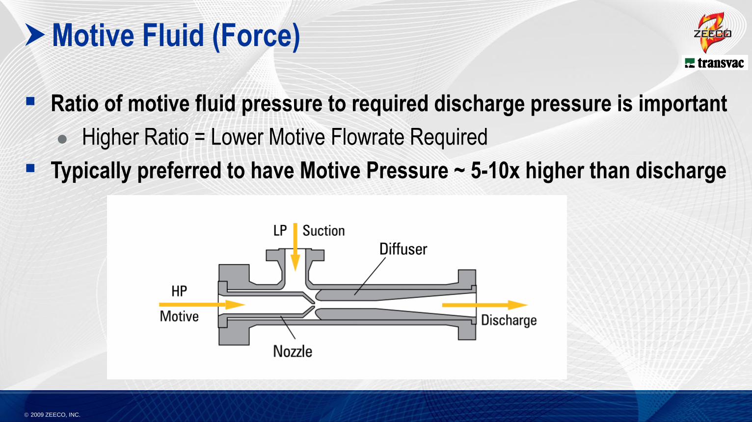
Motive Fluid (Force)
Ratio of motive fluid pressure to required discharge pressure is important
Higher Ratio = Lower Motive Flowrate Required
Typically preferred to have Motive Pressure ~ 5-10x higher than discharge
2009 ZEECO, INC.
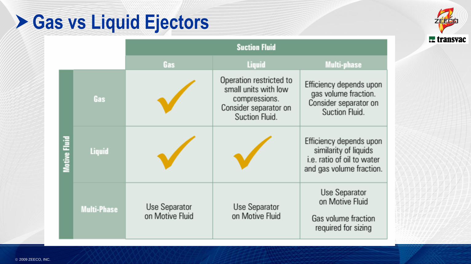
Gas vs Liquid Ejectors
2009 ZEECO, INC.
Gas Ejectors
Potential motive fluids:
Gas routed from a production separator
Fuel gas
Nitrogen
Small sidestream from a gas lift or gas injection compressor discharge
Typical usage: 2-8 kg of motive for every kg of flare gas recovered
Compression Ratio:
Up to 8:1 ratio for Transvac 1-stage (other vendors typically to 4.5:1)
Up to 40:1 ratio for multi-stage Transvac
2009 ZEECO, INC.
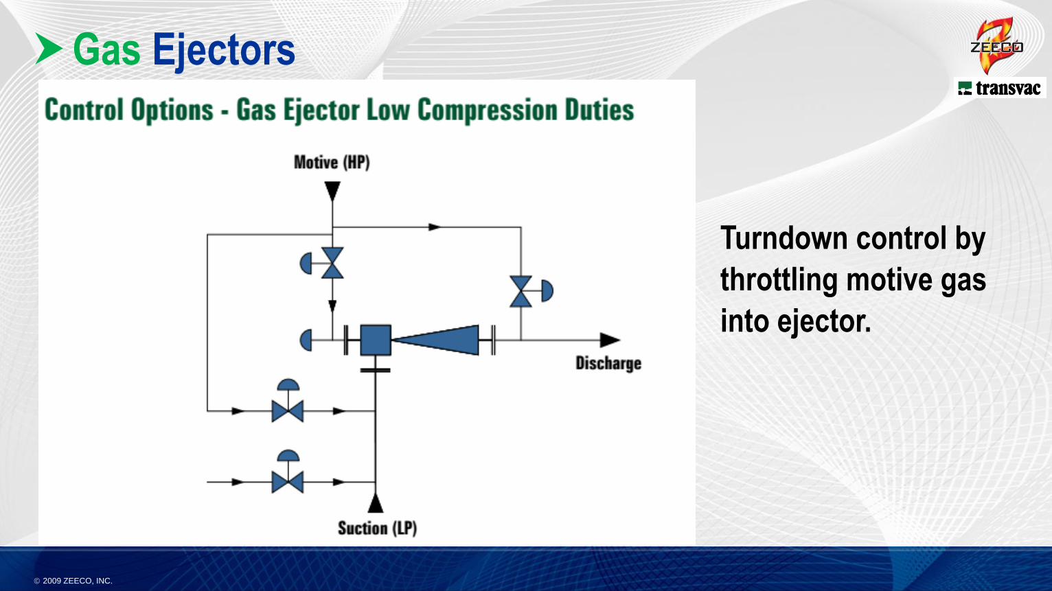
Gas Ejectors
Turndown control by
throttling motive gas
into ejector.
2009 ZEECO, INC.
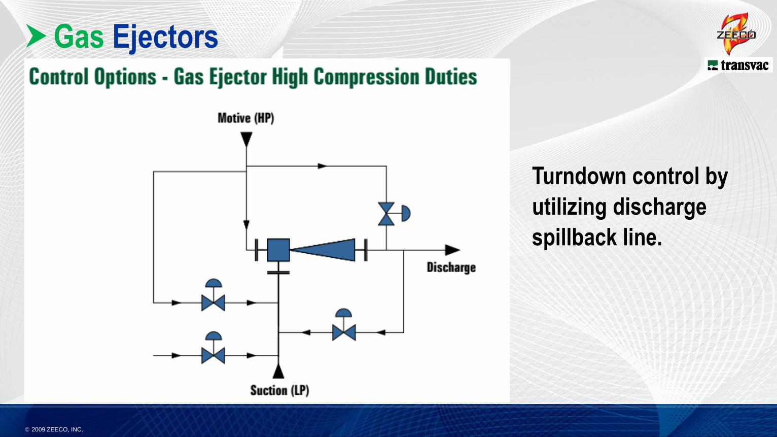
Gas Ejectors
Turndown control by
utilizing discharge
spillback line.
2009 ZEECO, INC.
Liquid Ejectors
Potential motive fluids:
Dedicated water pump
Spare capacity (sidestream) from existing water pump
Typical usage: 0.03 to 0.10 m3 of motive liquid for every m3 of flare gas recovered
Compression:
Up to 150bar discharge pressure available
Typical Flare Gas Recovery applications are normally 10 bar or less
2009 ZEECO, INC.
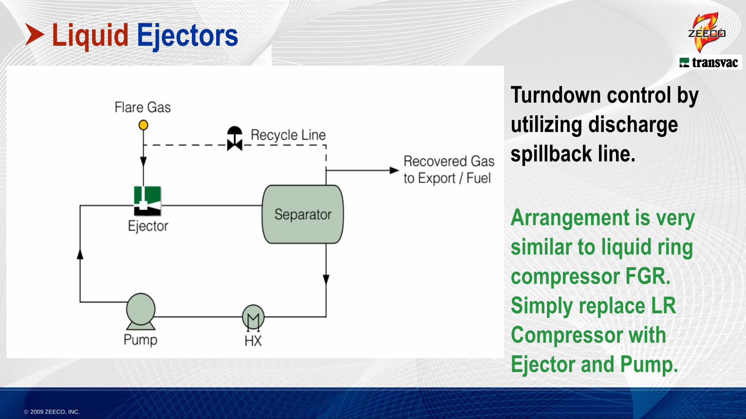
Liquid Ejectors
Turndown control by
utilizing discharge
spillback line.
Arrangement is very
similar to liquid ring
compressor FGR.
Simply replace LR
Compressor with
Ejector and Pump.
2009 ZEECO, INC.
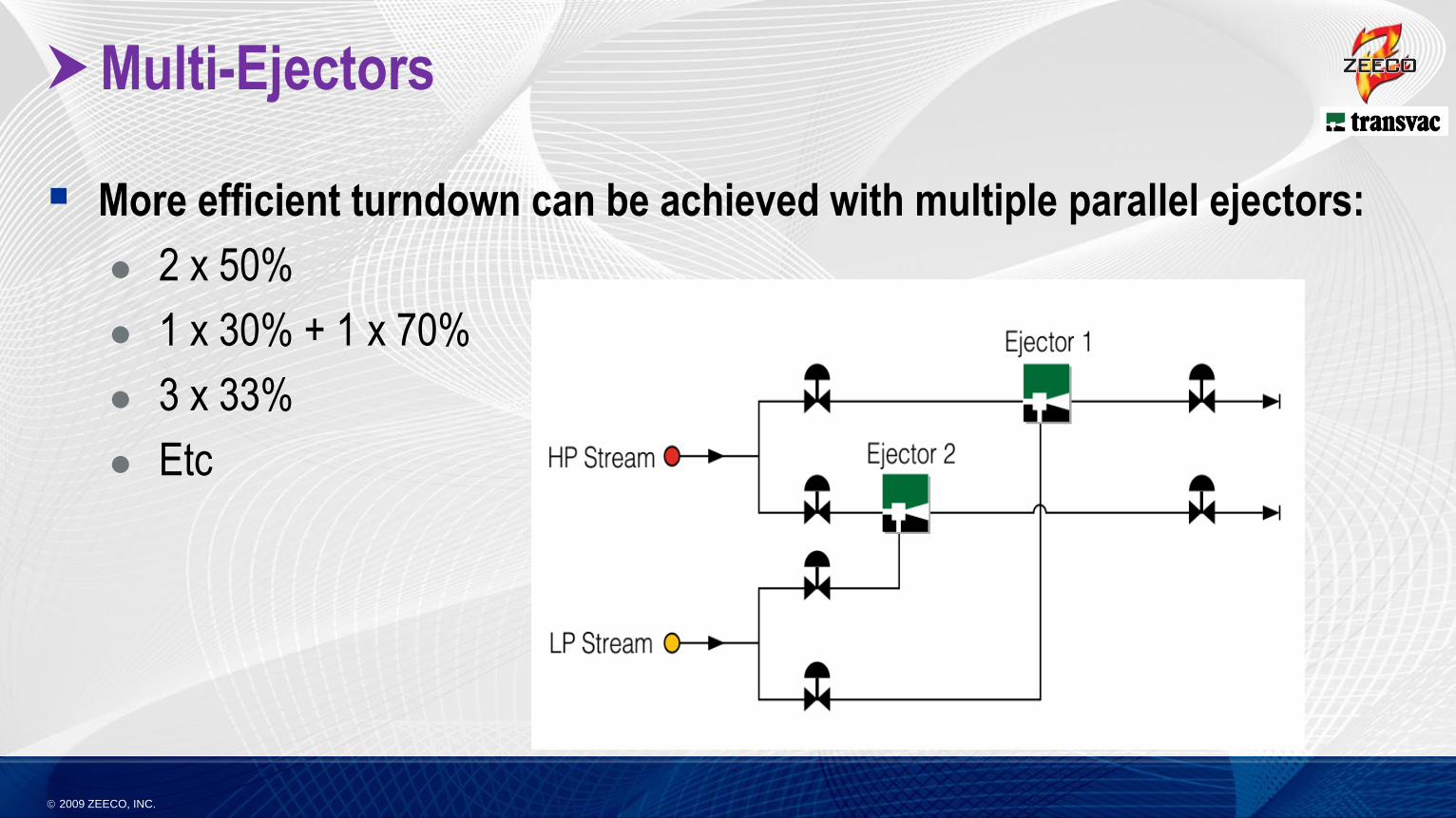
Multi-Ejectors
More efficient turndown can be achieved with multiple parallel ejectors:
2 x 50%
1 x 30% + 1 x 70%
3 x 33%
Etc
2009 ZEECO, INC.
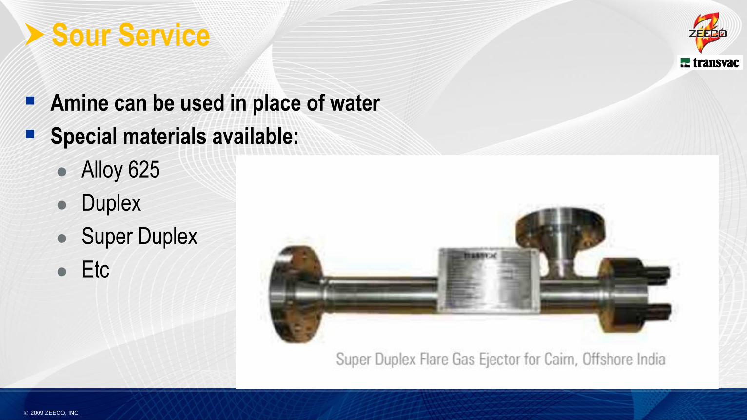
Sour Service
Amine can be used in place of water
Special materials available:
Alloy 625
Duplex
Super Duplex
Etc
2009 ZEECO, INC.
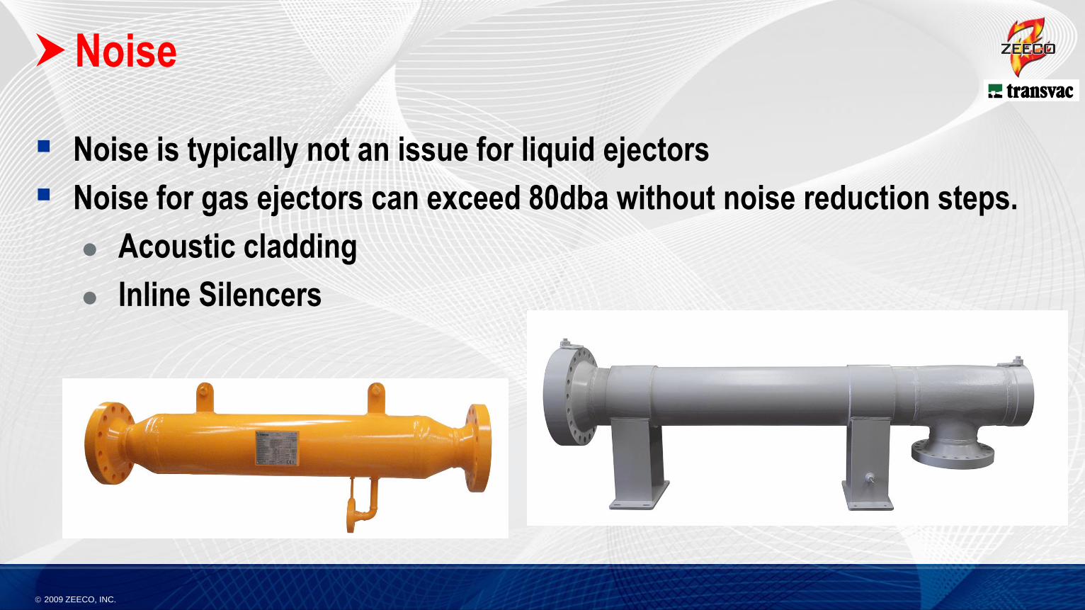
Noise
Noise is typically not an issue for liquid ejectors
Noise for gas ejectors can exceed 80dba without noise reduction steps.
Acoustic cladding
Inline Silencers
2009 ZEECO, INC.
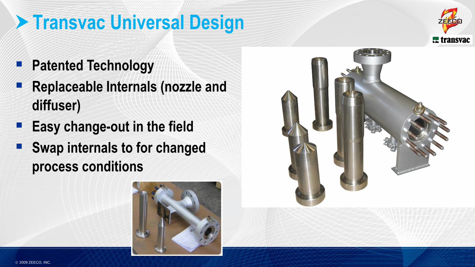
Transvac Universal Design
Patented Technology
Replaceable Internals (nozzle and
diffuser)
Easy change-out in the field
Swap internals to for changed
process conditions
2009 ZEECO, INC.
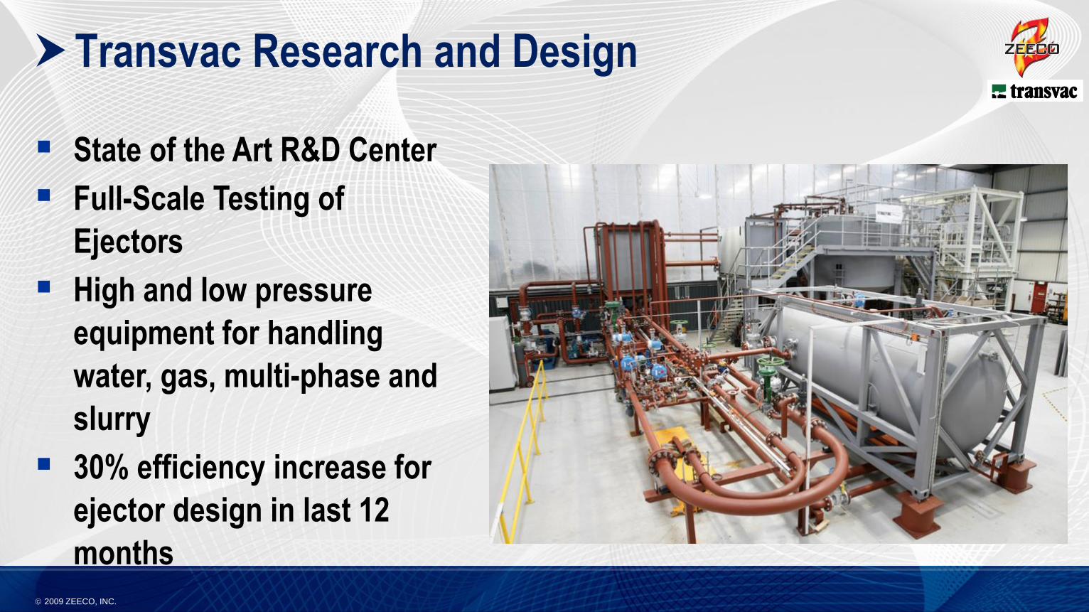
Transvac Research and Design
State of the Art R&D Center
Full-Scale Testing of
Ejectors
High and low pressure
equipment for handling
water, gas, multi-phase and
slurry
30% efficiency increase for
ejector design in last 12
months
2009 ZEECO, INC.
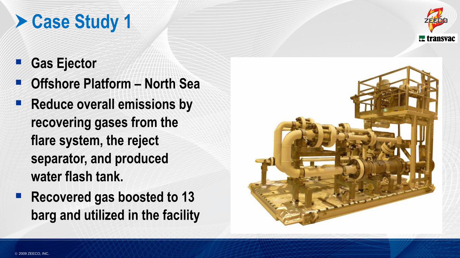
Case Study 1
Gas Ejector
Offshore Platform – North Sea
Reduce overall emissions by
recovering gases from the
flare system, the reject
separator, and produced
water flash tank.
Recovered gas boosted to 13
barg and utilized in the facility
2009 ZEECO, INC.
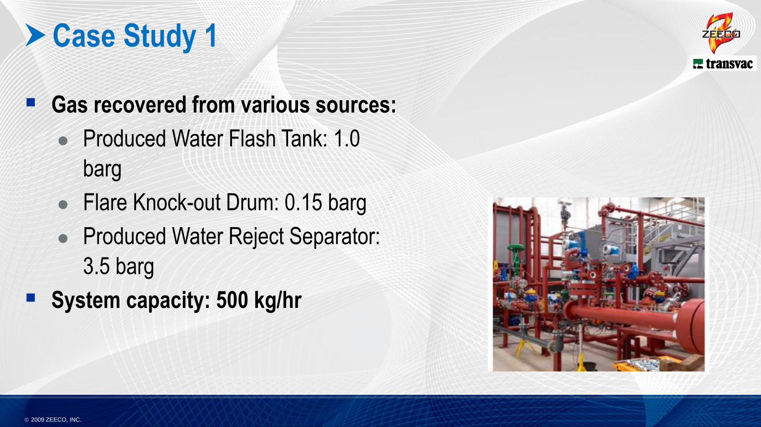
Case Study 1
Gas recovered from various sources:
Produced Water Flash Tank: 1.0
barg
Flare Knock-out Drum: 0.15 barg
Produced Water Reject Separator:
3.5 barg
System capacity: 500 kg/hr
2009 ZEECO, INC.
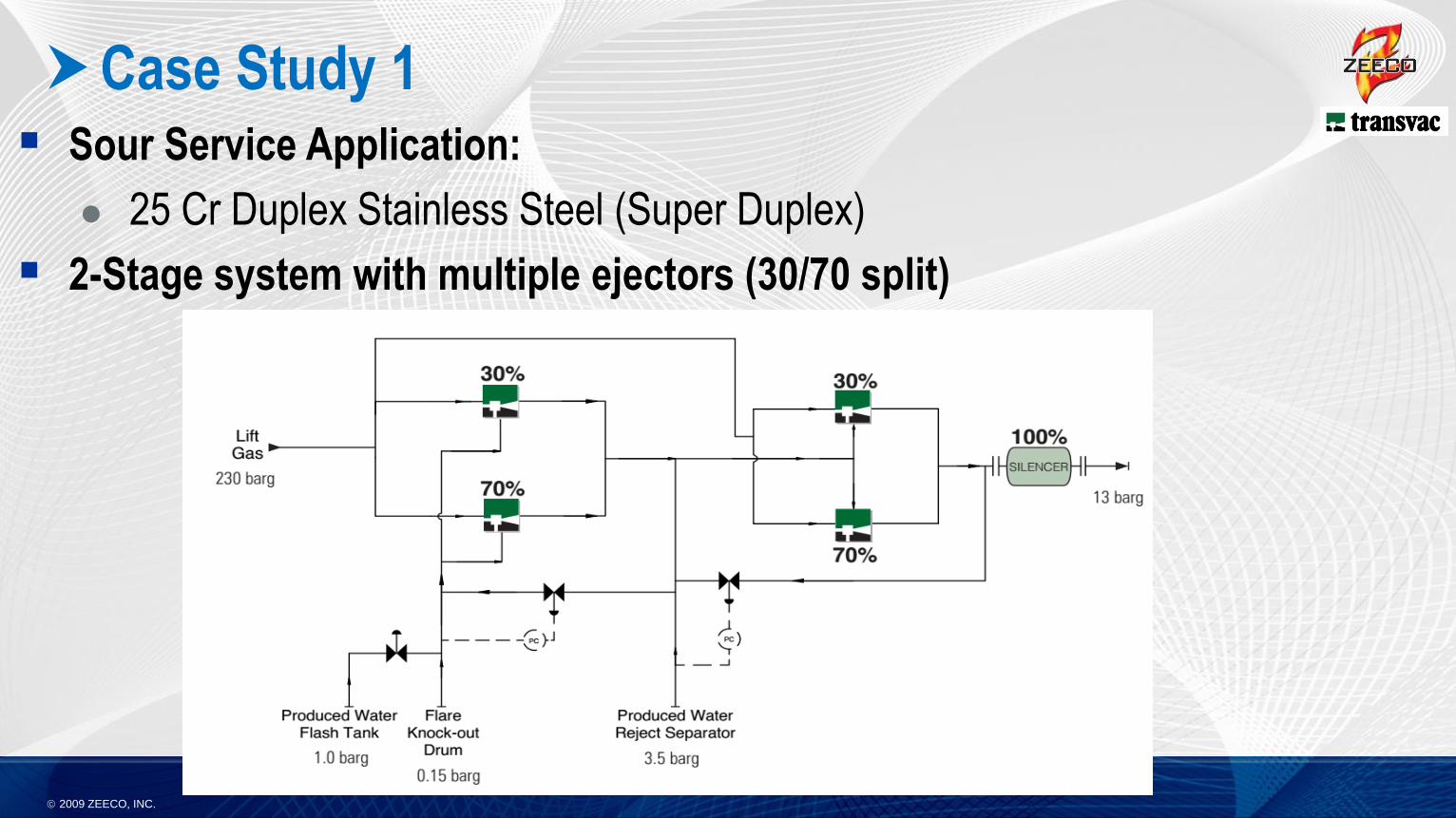
Case Study 1 Sour Service Application:
25 Cr Duplex Stainless Steel (Super Duplex)
2-Stage system with multiple ejectors (30/70 split)
2009 ZEECO, INC.
Case Study 1 Project Outcome:
Commissioned in 2014
Actual gas flowrate less than predicted so normally only the 30% ejector is
being utilized.
2009 ZEECO, INC.
Case Study 2
Liquid Ejector
Onshore – Middle East
Recover flare gas at oil and gas gathering facility.
Recovered gas routed to the existing plant bulk separator and then to
the gas lift compressors
Small sidestream from an existing Water Injection Pump used to
provide the motive water to the ejector.
Existing bulk separator had sufficient capacity to accept the multi-
phase discharge flow from the ejector
2009 ZEECO, INC.
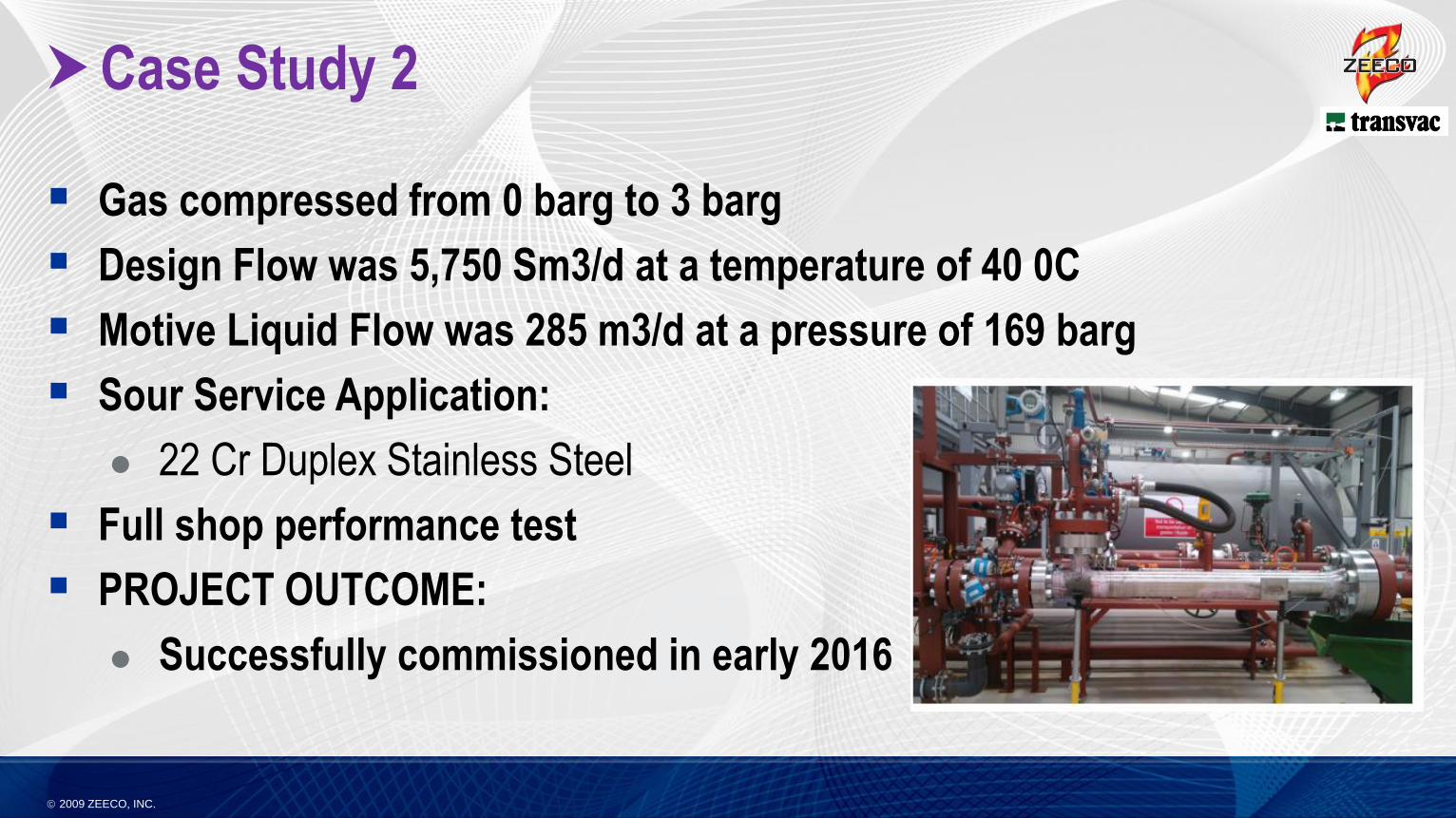
Case Study 2
Gas compressed from 0 barg to 3 barg
Design Flow was 5,750 Sm3/d at a temperature of 40 0C
Motive Liquid Flow was 285 m3/d at a pressure of 169 barg
Sour Service Application:
22 Cr Duplex Stainless Steel
Full shop performance test
PROJECT OUTCOME:
Successfully commissioned in early 2016
2009 ZEECO, INC.
Conclusion
Flare Gas Recovery offers good solution for reducing flaring and reducing
emissions.
Several technologies exist for gas compression in FGR systems, each having
unique benefits and drawbacks.
In many situations Liquid or Gas Ejectors offer an ideal solutuion
2009 ZEECO, INC.
Contact Information
Trevor Leagas – Flare Gas Recovery Manager – Europe & Middle East, Zeeco, Inc
Email: [email protected]
Phone: +1-918-892-8720
Greg Seefeldt, PE – Manager, Vapor Control Products
Email: [email protected]
Phone: 918-893-8210

2009 ZEECO, INC.
Questions?