ekspert™ ultralc systems - sciex · this guide is intended for laboratory technicians who are...
TRANSCRIPT

ekspert™ ultraLC Systems
Hardware User Guide
RUO-IDV-05-0871-ADecember 2013
This document is provided to customers who have purchased AB SCIEX equipment to use in the operation of such AB SCIEX equipment. This document is copyright protected and any reproduction of this document or any part of this document is strictly prohibited, except as AB SCIEX may authorize in writing.
Software that may be described in this document is furnished under a license agreement. It is against the law to copy, modify, or distribute the software on any medium, except as specifically allowed in the license agreement. Furthermore, the license agreement may prohibit the software from being disassembled, reverse engineered, or decompiled for any purpose. Warranties are as stated therein.
Portions of this document may make reference to other manufacturers and/or their products, which may contain parts whose names are registered as trademarks and/or function as trademarks of their respective owners. Any such use is intended only to designate those manufacturers' products as supplied by AB SCIEX for incorporation into its equipment and does not imply any right and/or license to use or permit others to use such manufacturers' and/or their product names as trademarks.
AB SCIEX warranties are limited to those express warranties provided at the time of sale or license of its products and are AB SCIEX’s sole and exclusive representations, warranties, and obligations. AB SCIEX makes no other warranty of any kind whatsoever, expressed or implied, including without limitation, warranties of merchantability or fitness for a particular purpose, whether arising from a statute or otherwise in law or from a course of dealing or usage of trade, all of which are expressly disclaimed, and assumes no responsibility or contingent liability, including indirect or consequential damages, for any use by the purchaser or for any adverse circumstances arising therefrom.
For research use only. Not for use in diagnostic procedures.
The trademarks mentioned herein are the property of AB Sciex Pte. Ltd. or their respective owners. Eksigent is a division of AB Sciex, LLC.
AB SCIEX™ is being used under license.
© 2013 AB Sciex Pte. Ltd.
Printed in Canada.
ekspert™ ultraLC Systems Hardware User Guide
2 of 162 RUO-IDV-05-0871-A | D5030929 B
AB Sciex LLC1201 Radio RoadRedwood City CA94065 USA
Revision History
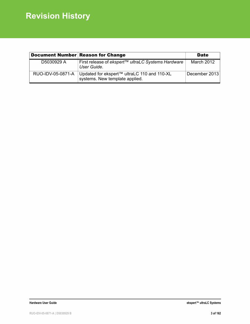
Document Number Reason for Change DateD5030929 A First release of ekspert™ ultraLC Systems Hardware
User Guide.March 2012
RUO-IDV-05-0871-A Updated for ekspert™ ultraLC 110 and 110-XL systems. New template applied.
December 2013
Hardware User Guide ekspert™ ultraLC Systems
RUO-IDV-05-0871-A | D5030929 B 3 of 162

Revision History
ekspert™ ultraLC Systems Hardware User Guide
4 of 162 RUO-IDV-05-0871-A | D5030929 B
Contents
Chapter 1 Operational Precautions and Limitations . . . . . . . . . . . . . . . . . . . . . . 9
General Safety Information . . . . . . . . . . . . . . . . . . . . . . . . . . . . . . . . . . . . . . . . . .9Customer Documentation . . . . . . . . . . . . . . . . . . . . . . . . . . . . . . . . . . . . . . . . . . .9Electrical Precautions . . . . . . . . . . . . . . . . . . . . . . . . . . . . . . . . . . . . . . . . . . . . . .9
Protective Earth Conductor . . . . . . . . . . . . . . . . . . . . . . . . . . . . . . . . . . . . . . .10Chemical Precautions . . . . . . . . . . . . . . . . . . . . . . . . . . . . . . . . . . . . . . . . . . . . .10
System Safe Fluids . . . . . . . . . . . . . . . . . . . . . . . . . . . . . . . . . . . . . . . . . . . . .11Ventilation Precautions . . . . . . . . . . . . . . . . . . . . . . . . . . . . . . . . . . . . . . . . . . . .11Environmental Precautions . . . . . . . . . . . . . . . . . . . . . . . . . . . . . . . . . . . . . . . . .11Decommissioning and Disposal . . . . . . . . . . . . . . . . . . . . . . . . . . . . . . . . . . . . .12Qualified Personnel . . . . . . . . . . . . . . . . . . . . . . . . . . . . . . . . . . . . . . . . . . . . . . .12Equipment Use and Modification . . . . . . . . . . . . . . . . . . . . . . . . . . . . . . . . . . . .12
Chapter 2 Hazards Symbols . . . . . . . . . . . . . . . . . . . . . . . . . . . . . . . . . . . . . . . . . 15
Occupational Health and Safety Symbols . . . . . . . . . . . . . . . . . . . . . . . . . . . . . .15Symbols, Indicators, and Labels . . . . . . . . . . . . . . . . . . . . . . . . . . . . . . . . . . . . .16
Chapter 3 Principles of Operation . . . . . . . . . . . . . . . . . . . . . . . . . . . . . . . . . . . . 17
ekspert™ ultraLC 100/110 Pump . . . . . . . . . . . . . . . . . . . . . . . . . . . . . . . . . . . .17Component . . . . . . . . . . . . . . . . . . . . . . . . . . . . . . . . . . . . . . . . . . . . . . . . . . .18Options . . . . . . . . . . . . . . . . . . . . . . . . . . . . . . . . . . . . . . . . . . . . . . . . . . . . . .20
ekspert ultraLC 100/110 Autosampler . . . . . . . . . . . . . . . . . . . . . . . . . . . . . . . . .20Features . . . . . . . . . . . . . . . . . . . . . . . . . . . . . . . . . . . . . . . . . . . . . . . . . . . . .21Components . . . . . . . . . . . . . . . . . . . . . . . . . . . . . . . . . . . . . . . . . . . . . . . . . .22Options . . . . . . . . . . . . . . . . . . . . . . . . . . . . . . . . . . . . . . . . . . . . . . . . . . . . . .25Injection Principles . . . . . . . . . . . . . . . . . . . . . . . . . . . . . . . . . . . . . . . . . . . . . .25Syringe and Injection Volumes . . . . . . . . . . . . . . . . . . . . . . . . . . . . . . . . . . . .26
ekspert ultraLC 100-XL/110-XL Autosampler . . . . . . . . . . . . . . . . . . . . . . . . . . .26Features . . . . . . . . . . . . . . . . . . . . . . . . . . . . . . . . . . . . . . . . . . . . . . . . . . . . .27Components . . . . . . . . . . . . . . . . . . . . . . . . . . . . . . . . . . . . . . . . . . . . . . . . . .28Well Plate Types and Adapters . . . . . . . . . . . . . . . . . . . . . . . . . . . . . . . . . . . .32Options . . . . . . . . . . . . . . . . . . . . . . . . . . . . . . . . . . . . . . . . . . . . . . . . . . . . . .34
ekspert ultraLC 100/110 Column Oven . . . . . . . . . . . . . . . . . . . . . . . . . . . . . . . .34Components . . . . . . . . . . . . . . . . . . . . . . . . . . . . . . . . . . . . . . . . . . . . . . . . . .35Sensors . . . . . . . . . . . . . . . . . . . . . . . . . . . . . . . . . . . . . . . . . . . . . . . . . . . . . .36Column Oven Controls . . . . . . . . . . . . . . . . . . . . . . . . . . . . . . . . . . . . . . . . . .36Options . . . . . . . . . . . . . . . . . . . . . . . . . . . . . . . . . . . . . . . . . . . . . . . . . . . . . .37
Tips for Handling Samples . . . . . . . . . . . . . . . . . . . . . . . . . . . . . . . . . . . . . . . . .37Theory of Operation—Liquid Chromatography . . . . . . . . . . . . . . . . . . . . . . . . . .37
Injection Mode Overview . . . . . . . . . . . . . . . . . . . . . . . . . . . . . . . . . . . . . . . . .38Full Loop Injections . . . . . . . . . . . . . . . . . . . . . . . . . . . . . . . . . . . . . . . . . . . . .38Partial Loop Injections . . . . . . . . . . . . . . . . . . . . . . . . . . . . . . . . . . . . . . . . . . .42µL Pickup . . . . . . . . . . . . . . . . . . . . . . . . . . . . . . . . . . . . . . . . . . . . . . . . . . . . .46Viscous Samples . . . . . . . . . . . . . . . . . . . . . . . . . . . . . . . . . . . . . . . . . . . . . . .52Using Air Segments to Reduce Flush Volume . . . . . . . . . . . . . . . . . . . . . . . .52
Hardware User Guide ekspert™ ultraLC Systems
RUO-IDV-05-0871-A | D5030929 B 5 of 162
Contents
ekspert™ ultraLC Systems Flow Path . . . . . . . . . . . . . . . . . . . . . . . . . . . . . . . .54
Chapter 4 Operating Instructions. . . . . . . . . . . . . . . . . . . . . . . . . . . . . . . . . . . . . 57
ekspert™ ultraLC 100/110 Pump . . . . . . . . . . . . . . . . . . . . . . . . . . . . . . . . . . . .57Start the Pump . . . . . . . . . . . . . . . . . . . . . . . . . . . . . . . . . . . . . . . . . . . . . . . . .57Purge the Pumps . . . . . . . . . . . . . . . . . . . . . . . . . . . . . . . . . . . . . . . . . . . . . . .58Perform a Leak Check . . . . . . . . . . . . . . . . . . . . . . . . . . . . . . . . . . . . . . . . . . .59Change Seal Wash Solvent . . . . . . . . . . . . . . . . . . . . . . . . . . . . . . . . . . . . . . .59Prime the Seal Wash . . . . . . . . . . . . . . . . . . . . . . . . . . . . . . . . . . . . . . . . . . . .60Short-term Shutdown . . . . . . . . . . . . . . . . . . . . . . . . . . . . . . . . . . . . . . . . . . . .61Guidelines for Controlling Sample Throughput . . . . . . . . . . . . . . . . . . . . . . . .61Guidelines for Using the Sample Temperature Control Option (STC) . . . . . . .61
ekspert ultraLC 100/110 Autosampler . . . . . . . . . . . . . . . . . . . . . . . . . . . . . . . . .62Start the ultraLC 100/110 Autosampler . . . . . . . . . . . . . . . . . . . . . . . . . . . . . .62Open the Door . . . . . . . . . . . . . . . . . . . . . . . . . . . . . . . . . . . . . . . . . . . . . . . . .63Remove the Cover . . . . . . . . . . . . . . . . . . . . . . . . . . . . . . . . . . . . . . . . . . . . . .64
ekspert ultraLC 100-XL/110-XL Autosampler . . . . . . . . . . . . . . . . . . . . . . . . . . .65Start the ultraLC 100-XL/110-XL Autosampler . . . . . . . . . . . . . . . . . . . . . . . .65Open the Front Cover . . . . . . . . . . . . . . . . . . . . . . . . . . . . . . . . . . . . . . . . . . .66Open the Foot Door . . . . . . . . . . . . . . . . . . . . . . . . . . . . . . . . . . . . . . . . . . . . .67Remove the Bottom Front Cover . . . . . . . . . . . . . . . . . . . . . . . . . . . . . . . . . . .67
Guidelines for the ultraLC 100/110 and 100-XL/110-XL Autosamplers . . . . . . .68Guidelines for Handling Samples . . . . . . . . . . . . . . . . . . . . . . . . . . . . . . . . . .68Guidelines for Working with Sticky Compounds and Matrixes . . . . . . . . . . . .69Working with UHPLC . . . . . . . . . . . . . . . . . . . . . . . . . . . . . . . . . . . . . . . . . . . .69Guidelines for Optimizing for Maximum Performance . . . . . . . . . . . . . . . . . . .70Guidelines Working with Sample Containers (Vials and Well Plates) . . . . . . .70
ekspert ultraLC 100/110 Column Oven . . . . . . . . . . . . . . . . . . . . . . . . . . . . . . . .71Start the Column Oven . . . . . . . . . . . . . . . . . . . . . . . . . . . . . . . . . . . . . . . . . .71
Create Nut and Ferrule Connections . . . . . . . . . . . . . . . . . . . . . . . . . . . . . . . . .71
Chapter 5 Service and Maintenance . . . . . . . . . . . . . . . . . . . . . . . . . . . . . . . . . . 75
ekspert™ ultraLC 100/110 Pump . . . . . . . . . . . . . . . . . . . . . . . . . . . . . . . . . . . .75Basic Maintenance Schedule . . . . . . . . . . . . . . . . . . . . . . . . . . . . . . . . . . . . .75Tighten Fittings and Check Valve Holders . . . . . . . . . . . . . . . . . . . . . . . . . . .76Clean the Surfaces . . . . . . . . . . . . . . . . . . . . . . . . . . . . . . . . . . . . . . . . . . . . .76Prepare for Maintenance . . . . . . . . . . . . . . . . . . . . . . . . . . . . . . . . . . . . . . . . .76Maintain Flow Line Components . . . . . . . . . . . . . . . . . . . . . . . . . . . . . . . . . . .76Clean or Replace the Outlet Filter . . . . . . . . . . . . . . . . . . . . . . . . . . . . . . . . . .78Change Mobile Phase Solvents . . . . . . . . . . . . . . . . . . . . . . . . . . . . . . . . . . .79Maintain the Degasser . . . . . . . . . . . . . . . . . . . . . . . . . . . . . . . . . . . . . . . . . . .81Replace the Mixer . . . . . . . . . . . . . . . . . . . . . . . . . . . . . . . . . . . . . . . . . . . . . .82Maintain the Seal Wash System . . . . . . . . . . . . . . . . . . . . . . . . . . . . . . . . . . .82Prepare the Pump for Long-Term Storage . . . . . . . . . . . . . . . . . . . . . . . . . . .84Prepare the Pump for Transport . . . . . . . . . . . . . . . . . . . . . . . . . . . . . . . . . . .84
ekspert ultraLC 100/110 Autosampler . . . . . . . . . . . . . . . . . . . . . . . . . . . . . . . . .85Prepare for Maintenance . . . . . . . . . . . . . . . . . . . . . . . . . . . . . . . . . . . . . . . . .86Surface Cleaning . . . . . . . . . . . . . . . . . . . . . . . . . . . . . . . . . . . . . . . . . . . . . . .86Replace the Injection Valve and Rotor Seal . . . . . . . . . . . . . . . . . . . . . . . . . .86Replace the Sample Loop . . . . . . . . . . . . . . . . . . . . . . . . . . . . . . . . . . . . . . . .88
ekspert™ ultraLC Systems Hardware User Guide
6 of 162 RUO-IDV-05-0871-A | D5030929 B
Contents
Replace the Sample Needle . . . . . . . . . . . . . . . . . . . . . . . . . . . . . . . . . . . . . .89Replace the Air Needle . . . . . . . . . . . . . . . . . . . . . . . . . . . . . . . . . . . . . . . . . .91Replace the Syringe . . . . . . . . . . . . . . . . . . . . . . . . . . . . . . . . . . . . . . . . . . . .94Replace the Syringe Plunger and Plunger Tip . . . . . . . . . . . . . . . . . . . . . . . .98Replace the Syringe Valve . . . . . . . . . . . . . . . . . . . . . . . . . . . . . . . . . . . . . . .98Fuses . . . . . . . . . . . . . . . . . . . . . . . . . . . . . . . . . . . . . . . . . . . . . . . . . . . . . . .101
ekspert ultraLC 100-XL/110-XL Autosampler . . . . . . . . . . . . . . . . . . . . . . . . . .102Prepare for Maintenance . . . . . . . . . . . . . . . . . . . . . . . . . . . . . . . . . . . . . . . .102Maintain the Waste Tubing . . . . . . . . . . . . . . . . . . . . . . . . . . . . . . . . . . . . . .102Clean the Condensation Tubing . . . . . . . . . . . . . . . . . . . . . . . . . . . . . . . . . .105Replace the Injection Valve and Rotor Seal . . . . . . . . . . . . . . . . . . . . . . . . .107Replace the Sample Loop . . . . . . . . . . . . . . . . . . . . . . . . . . . . . . . . . . . . . . .110Replace the Sample Needle . . . . . . . . . . . . . . . . . . . . . . . . . . . . . . . . . . . . .110Replace the Puncturing Air Needle . . . . . . . . . . . . . . . . . . . . . . . . . . . . . . . .112Replace the Syringe . . . . . . . . . . . . . . . . . . . . . . . . . . . . . . . . . . . . . . . . . . .114Replace the Syringe Valve . . . . . . . . . . . . . . . . . . . . . . . . . . . . . . . . . . . . . .116Clean the Wash Block . . . . . . . . . . . . . . . . . . . . . . . . . . . . . . . . . . . . . . . . . .119Replace Fuses . . . . . . . . . . . . . . . . . . . . . . . . . . . . . . . . . . . . . . . . . . . . . . . .119
Prepare the Autosampler for Long-Term Storage . . . . . . . . . . . . . . . . . . . . . . .120Prepare the Autosampler for Transport . . . . . . . . . . . . . . . . . . . . . . . . . . . . . . .120ekspert ultraLC 100/110 Column Oven . . . . . . . . . . . . . . . . . . . . . . . . . . . . . . .121
Install a New Supply Line . . . . . . . . . . . . . . . . . . . . . . . . . . . . . . . . . . . . . . .121
Chapter 6 Troubleshooting the ekspert™ ultraLC System. . . . . . . . . . . . . . . 123
ekspert™ ultraLC 100/110 Pump . . . . . . . . . . . . . . . . . . . . . . . . . . . . . . . . . . .123ekspert ultraLC 100/110 Autosampler . . . . . . . . . . . . . . . . . . . . . . . . . . . . . . . .126
Instrument Errors . . . . . . . . . . . . . . . . . . . . . . . . . . . . . . . . . . . . . . . . . . . . . .127Analytical Troubleshooting . . . . . . . . . . . . . . . . . . . . . . . . . . . . . . . . . . . . . .127
ekspert ultraLC 100-XL/110-XL Autosampler . . . . . . . . . . . . . . . . . . . . . . . . . .129Instrument Errors . . . . . . . . . . . . . . . . . . . . . . . . . . . . . . . . . . . . . . . . . . . . . .130Analytical Troubleshooting . . . . . . . . . . . . . . . . . . . . . . . . . . . . . . . . . . . . . .130
ekspert ultraLC 100/110 Column Oven . . . . . . . . . . . . . . . . . . . . . . . . . . . . . . .133Warnings, Alarms, and Error Codes on the Front Panel . . . . . . . . . . . . . . . .133
Appendix A Error Codes . . . . . . . . . . . . . . . . . . . . . . . . . . . . . . . . . . . . . . . . . . .137
ekspert™ ultraLC 100/110 Pump . . . . . . . . . . . . . . . . . . . . . . . . . . . . . . . . . . .137ekspert ultraLC 100/110 Autosampler . . . . . . . . . . . . . . . . . . . . . . . . . . . . . . . .137ekspert ultraLC 100-XL/110-XL Autosampler . . . . . . . . . . . . . . . . . . . . . . . . . .139ekspert ultraLC 100/110 Column Oven . . . . . . . . . . . . . . . . . . . . . . . . . . . . . . .140
Appendix B Components and Spare Parts . . . . . . . . . . . . . . . . . . . . . . . . . . . . .141
ekspert™ ultraLC 100/110 Pump . . . . . . . . . . . . . . . . . . . . . . . . . . . . . . . . . . .141ekspert ultraLC 100/110 Autosampler . . . . . . . . . . . . . . . . . . . . . . . . . . . . . . . .142ekspert ultraLC 100-XL/110-XL Autosampler . . . . . . . . . . . . . . . . . . . . . . . . . .143ekspert ultraLC 100/110 Column Oven . . . . . . . . . . . . . . . . . . . . . . . . . . . . . . .145
Appendix C ekspert™ ultraLC System Specifications . . . . . . . . . . . . . . . . . . .147
ekspert ultraLC 100/110 Pump . . . . . . . . . . . . . . . . . . . . . . . . . . . . . . . . . . . . .147ekspert ultraLC 100/110 Autosampler . . . . . . . . . . . . . . . . . . . . . . . . . . . . . . . .148ekspert ultraLC 100-XL/110-XL Autosampler . . . . . . . . . . . . . . . . . . . . . . . . . .150
Hardware User Guide ekspert™ ultraLC Systems
RUO-IDV-05-0871-A | D5030929 B 7 of 162
Contents
ekspert ultraLC 100/110 Column Oven . . . . . . . . . . . . . . . . . . . . . . . . . . . . . . .152
Appendix D Pump Log Counters . . . . . . . . . . . . . . . . . . . . . . . . . . . . . . . . . . . . .155
Appendix E Keypad Control of the Column Oven . . . . . . . . . . . . . . . . . . . . . . .157
ekspert™ ultraLC 100/110 Column Oven Keypad . . . . . . . . . . . . . . . . . . . . . .157Change to Software Control . . . . . . . . . . . . . . . . . . . . . . . . . . . . . . . . . . . . . . .158
Index . . . . . . . . . . . . . . . . . . . . . . . . . . . . . . . . . . . . . . . . . . . . . . . . . . . . . . . . . . . 159
ekspert™ ultraLC Systems Hardware User Guide
8 of 162 RUO-IDV-05-0871-A | D5030929 B
1
Operational Precautions and LimitationsThis guide is intended for laboratory technicians who are responsible for control and day-to-day maintenance of the ekspert™ ultraLC 100/110 and ekspert™ ultraLC 100-XL/110-XL systems. It is assumed that the user of this guide is familiar with standard laboratory terminology.
This section contains general safety-related information and provides regulatory compliance information. It also describes potential hazards and associated warnings for the system, and the precautions that should be taken to minimize the hazards.
In addition to this section, refer to Hazards Symbols on page 15 for information on the symbols and conventions used in the laboratory environment, on the system, and in this documentation. Refer to the Site Planning Guide for site requirements, including AC mains supply requirements.
General Safety InformationTo prevent personal injury or system damage, read, understand, and obey all safety precautions, warnings in this document, and labels on the system components. These labels are shown with international symbols. Failure to heed these warnings could result in serious injury.
This safety information is intended to supplement federal, state or provincial, and local environmental health and safety (EHS) regulations. The information provided covers system-related safety with regard to the operation of the system. It does not cover every safety procedure that should be practised. Ultimately, the user and the organization are responsible for compliance with federal, state or provincial, and local EHS regulations and for maintaining a safe laboratory environment.
For more information, refer to the appropriate laboratory reference material and standard operating procedures.
Customer DocumentationThe ekspert™ ultraLC Systems Site Planning Guide is provided to the customer prior to installation. The guides for the system are available on the software installation DVD.
Electrical Precautions
Note: For information about the ekspert™ ultraLC 110 HTC system, refer to the HTC PAL / PAL HTC-xt User Manual: Installation and Operation. For information about the ekspert™ ultraLC 110 HTS system, refer to the HTS PAL / HTX PAL, PAL HTS-xt / PAL HTX-xt User Manual: Installation and Operation.
WARNING! Electrical Shock Hazard: Use only qualified personnel for the installation of all electrical supplies and fixtures, and make sure that all installations adhere to local bylaws.
Hardware User Guide ekspert™ ultraLC Systems
RUO-IDV-05-0871-A | D5030929 B 9 of 162
Operational Precautions and Limitations
• Close all covers before operating the system.
• Replace faulty insulation on power cords immediately after discovery of the fault.
• Verify that the AC mains supply voltage is the voltage required for the instrument. Make sure power cords are connected to correct AC mains supply.
• Do not place the system in the vicinity of equipment that emit electromagnetic radiation.
For information on system electrical specifications, refer to the ekspert™ ultraLC Systems Site Planning Guide.
Protective Earth ConductorThe mains supply must include a correctly installed protective earth conductor that must be installed or checked by a qualified electrician before connecting the mass spectrometer. The mass spectrometer must be positioned to permit access to the mains supply connector to disconnect the device.
Chemical Precautions• Determine which chemicals might have been used in the system prior to service and
regular maintenance. Refer to Safety Data Sheets for the health and safety precautions that must be followed with chemicals.
• Work in a well-ventilated area.
• Always wear assigned personal protective equipment, including powder-free nitrile gloves, safety glasses and a laboratory coat.
• Follow required electrical safe work practices.
• Avoid ignition sources when working with flammable materials, such as isopropanol, methanol, and other flammable solvents.
• Take care in the use and disposal of chemicals and comply with all local regulations to avoid potential risk of personal injury.
• Avoid skin contact with chemicals during cleaning, and wash hands after use.
• Seal solvents bottles to minimize any risks related to solvent vapors.
• Perform regular leak checks on supply lines.
• Comply with all local regulations for the storage, handling, and disposal of biohazard, toxic, or radioactive materials.
WARNING! Electrical Shock Hazard: Do not remove instrument panels. Removal of panels might expose users to dangerous voltages. Only trained AB SCIEX field service employees (FSEs) should remove instrument panels.
WARNING! Electrical Shock Hazard: Do not intentionally interrupt the protective earth conductor. Any interruption of the protective earth conductor is likely to make the installation dangerous.
ekspert™ ultraLC Systems Hardware User Guide
10 of 162 RUO-IDV-05-0871-A | D5030929 B
Operational Precautions and Limitations
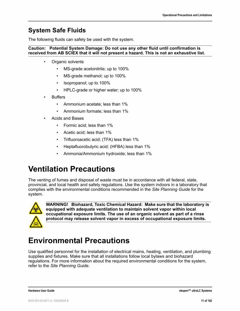
System Safe FluidsThe following fluids can safely be used with the system.
Caution: Potential System Damage: Do not use any other fluid until confirmation is received from AB SCIEX that it will not present a hazard. This is not an exhaustive list.
• Organic solvents
• MS-grade acetonitrile; up to 100%
• MS-grade methanol; up to 100%
• Isopropanol; up to 100%
• HPLC-grade or higher water; up to 100%
• Buffers
• Ammonium acetate; less than 1%
• Ammonium formate; less than 1%
• Acids and Bases
• Formic acid; less than 1%
• Acetic acid; less than 1%
• Trifluoroacetic acid; (TFA) less than 1%
• Heptafluorobutyric acid; (HFBA) less than 1%
• Ammonia/Ammonium hydroxide; less than 1%
Ventilation PrecautionsThe venting of fumes and disposal of waste must be in accordance with all federal, state, provincial, and local health and safety regulations. Use the system indoors in a laboratory that complies with the environmental conditions recommended in the Site Planning Guide for the system. .
Environmental PrecautionsUse qualified personnel for the installation of electrical mains, heating, ventilation, and plumbing supplies and fixtures. Make sure that all installations follow local bylaws and biohazard regulations. For more information about the required environmental conditions for the system, refer to the Site Planning Guide.
WARNING! Biohazard, Toxic Chemical Hazard: Make sure that the laboratory is equipped with adequate ventilation to maintain solvent vapor within local occupational exposure limits. The use of an organic solvent as part of a rinse protocol may release solvent vapor in excess of occupational exposure limits.
Hardware User Guide ekspert™ ultraLC Systems
RUO-IDV-05-0871-A | D5030929 B 11 of 162
Operational Precautions and Limitations
Decommissioning and DisposalDecontaminate the system before decommissioning following local regulations. Follow the AB SCIEX Red Tag process and complete an instrument Decontamination Form for instrument returns.
When removing the system from service, different materials must be separated and recycled according to national and local environmental regulations. Refer to Storage and Handling on page 97.
Do not dispose of system components or subassemblies, including computer parts, as unsorted municipal waste. Follow local municipal waste ordinances for proper disposal provisions to reduce the environmental impact of WEEE (waste, electrical, and electronic equipment). To make sure that you safely dispose of this equipment, contact an FSE for instructions.
European Union customers: Contact a local AB SCIEX Customer Service office for complimentary equipment pick-up and recycling.
Qualified PersonnelAfter installing the system, the AB SCIEX Field Service Employee (FSE) uses the Customer Familiarization Checklist to familiarize the customer with system operation, cleaning, and basic maintenance. Only qualified AB SCIEX personnel shall install and service the equipment. Only personnel qualified by AB SCIEX shall operate and maintain the equipment. Contact an FSE for more information.
Equipment Use and ModificationUse the system indoors in a laboratory that complies with the environmental conditions recommended in the system Site Planning Guide. If the system is used in an environment or in a manner not prescribed by AB SCIEX, the protection provided by the equipment can be impaired.
The system is intended for use in a Good Laboratory Practice (GLP) approved environment. Operators using the system should have an extensive understanding of GLP rules. Use this
DANGER! Explosion Hazard: Do not operate the system in an environment containing explosive gases. The system is not designed for operation in an explosive environment.
WARNING! Biohazard: For biohazardous material use, always follow local regulations for hazard assessment, control, and handling.
WARNING! Biohazard, Toxic Chemical Hazard: Follow all safety guidelines and applicable local regulations when handling, storing, and disposing of waste products.
ekspert™ ultraLC Systems Hardware User Guide
12 of 162 RUO-IDV-05-0871-A | D5030929 B
Operational Precautions and Limitations
system only for the intended use. Use of the system for any other purpose will cause unsafe situations.
Do not use the device if there is visible damage.
The ultraLC 100/110 pump is a high-pressure device. Always make sure pressure in the device is built up slowly. Gradually reduce the pressure to 0, by reducing the flow in steps, before disconnecting any tubing or before opening the purge valve. Sudden loss of pressure might damage the pump and the analytical column connected to it.
To maintain system performance, we recommend that the system be checked and that maintenance be performed regularly.
Unauthorized modification or operation of the system might cause personal injury and equipment damage, and might void the warranty. Erroneous data might be generated if the system is operating outside the recommended environmental conditions or with unauthorized modifications. Contact an AB SCIEX representative for more information on servicing the system.
Hardware User Guide ekspert™ ultraLC Systems
RUO-IDV-05-0871-A | D5030929 B 13 of 162

Operational Precautions and Limitations
ekspert™ ultraLC Systems Hardware User Guide
14 of 162 RUO-IDV-05-0871-A | D5030929 B
2
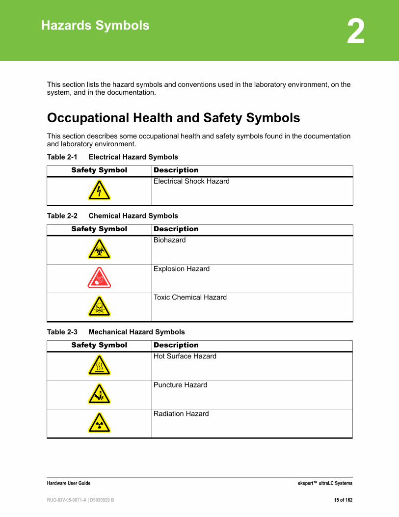
Hazards SymbolsThis section lists the hazard symbols and conventions used in the laboratory environment, on the system, and in the documentation.
Occupational Health and Safety SymbolsThis section describes some occupational health and safety symbols found in the documentation and laboratory environment.
Table 2-1 Electrical Hazard Symbols
Safety Symbol DescriptionElectrical Shock Hazard
Table 2-2 Chemical Hazard Symbols
Safety Symbol DescriptionBiohazard
Explosion Hazard
Toxic Chemical Hazard
Table 2-3 Mechanical Hazard Symbols
Safety Symbol DescriptionHot Surface Hazard
Puncture Hazard
Radiation Hazard
Hardware User Guide ekspert™ ultraLC Systems
RUO-IDV-05-0871-A | D5030929 B 15 of 162
Hazards Symbols
Symbols, Indicators, and LabelsThe following symbols and conventions are used throughout the guide.
Caution: Caution signifies an operation that could cause damage to the system or loss of data if precautions are not followed.
DANGER! Danger signifies an action which leads to severe injury or death.
WARNING! Warning signifies an operation that could cause personal injury if precautions are not followed.
Tip! A tip provides useful information that helps apply the techniques and procedures in the text for a specific need, and provides shortcuts, but is not essential to the completion of a procedure.
i
Note: A note emphasizes significant information in a procedure or description.
ekspert™ ultraLC Systems Hardware User Guide
16 of 162 RUO-IDV-05-0871-A | D5030929 B
3
Principles of OperationThe ekspert™ ultraLC system consists of:
• Two pumps: ekspert™ ultraLC 100/110 pump
• An autosampler: ekspert™ ultraLC 100/110, 100-XL/110-XL, or 110 HTC or HTS autosampler
• (Optional) Column oven: ekspert™ ultraLC 100/110 column oven
Traditional liquid chromatography (LC) using column particle sizes 3 µm to 5 µm has been named High Performance Liquid Chromatography (HPLC). Small particles generate high backpressure requiring LC pumps that can provide a constant mobile phase flow rate against backpressures up to 40 MPa (that is, 400 bar; approximately 5800 psi). Today, columns with even smaller particles (below 2 µm) are increasingly used. To support Ultra HPLC (UHPLC), the mobile phase pumps in this UHPLC system have a working range up to as much 1241 bar (18 000 psi).
The dual UHPLC pumps deliver accurately metered flows of solvent A and B to the mixing device, where solvent A and B are mixed to create the proper mobile phase composition. The resulting mobile phase flow rate is the sum of flow rate A and B. A typical flow rate for UHPLC separations is 200 µL/min to 800 µL/min. Refer to the section, ekspert™ ultraLC 100/110 Pump on page 17.
For gradient separations, the flow rates of pump A and B are adjusted to create a varying A:B ratio while keeping the sum of the flow rates constant. Downstream of the mixer, the mobile phase is directed to the separation column via the high-pressure sample injection valve of the autosampler.
The autosampler brings the sample from a sample vial into a loop on the injection valve. By rotating the valve, the content of the loop is injected into the mobile phase stream. Refer to ekspert ultraLC 100/110 Autosampler on page 20 or ekspert ultraLC 100-XL/110-XL Autosampler on page 26.
The column is mounted in a column oven to maintain a constant or elevated temperature during separation. Finally, the outlet of the column is connected to the solvent inlet of the ion source. Refer to the section, ekspert ultraLC 100/110 Column Oven on page 34.
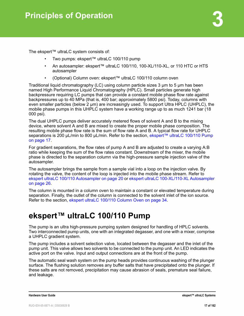
ekspert™ ultraLC 100/110 PumpThe pump is an ultra high-pressure pumping system designed for handling of HPLC solvents. Two interconnected pump units, one with an integrated degasser, and one with a mixer, comprise a UHPLC gradient system.
The pump includes a solvent selection valve, located between the degasser and the inlet of the pump unit. This valve allows two solvents to be connected to the pump unit. An LED indicates the active port on the valve. Input and output connections are at the front of the pump.
The automatic seal wash system on the pump heads provides continuous washing of the plunger surface. The flushing solution removes any buffer salts that have precipitated onto the plunger. If these salts are not removed, precipitation may cause abrasion of seals, premature seal failure, and leakage.
Hardware User Guide ekspert™ ultraLC Systems
RUO-IDV-05-0871-A | D5030929 B 17 of 162
Principles of Operation
The ekspert™ ultraLC software is required for operation of the ultraLC 100/110 pump. Refer to the ekspert™ ultraLC Systems Software User Guide for more information.
For a list of accessories and spares, refer to ekspert™ ultraLC 100/110 Pump on page 141.
Component
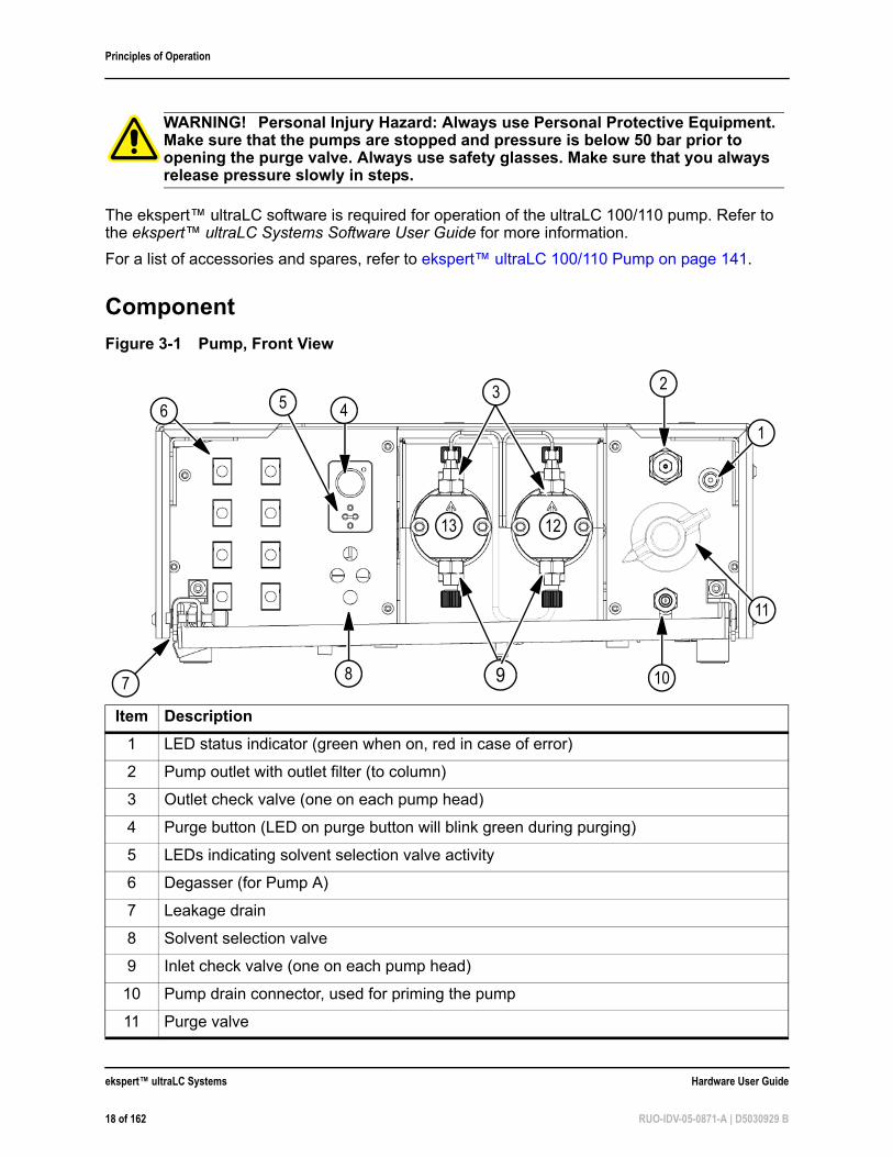
WARNING! Personal Injury Hazard: Always use Personal Protective Equipment. Make sure that the pumps are stopped and pressure is below 50 bar prior to opening the purge valve. Always use safety glasses. Make sure that you always release pressure slowly in steps.
Figure 3-1 Pump, Front View
Item Description
1 LED status indicator (green when on, red in case of error)
2 Pump outlet with outlet filter (to column)
3 Outlet check valve (one on each pump head)
4 Purge button (LED on purge button will blink green during purging)
5 LEDs indicating solvent selection valve activity
6 Degasser (for Pump A)
7 Leakage drain
8 Solvent selection valve
9 Inlet check valve (one on each pump head)
10 Pump drain connector, used for priming the pump
11 Purge valve
5
11
2
146
8 107 9
3
13 12
ekspert™ ultraLC Systems Hardware User Guide
18 of 162 RUO-IDV-05-0871-A | D5030929 B
Principles of Operation
12 Right pump head
13 Left pump head
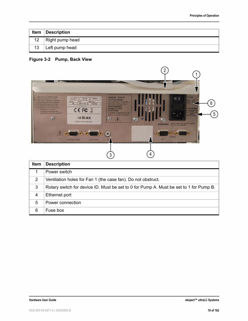
Figure 3-2 Pump, Back View
[
Item Description
1 Power switch
2 Ventilation holes for Fan 1 (the case fan). Do not obstruct.
3 Rotary switch for device ID. Must be set to 0 for Pump A. Must be set to 1 for Pump B.
4 Ethernet port
5 Power connection
6 Fuse box
Item Description
6
21
5
43
Hardware User Guide ekspert™ ultraLC Systems
RUO-IDV-05-0871-A | D5030929 B 19 of 162
Principles of Operation
Options• Alternative static mixer sizes
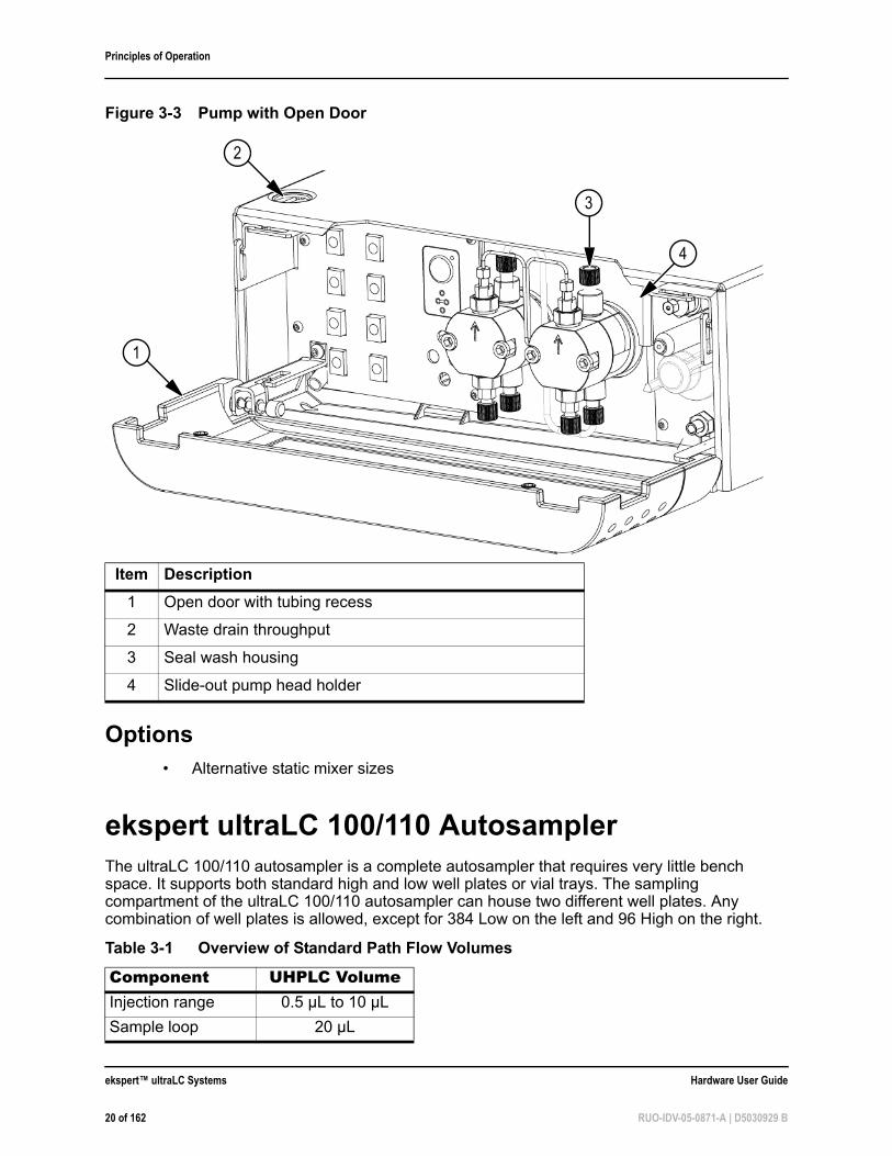
ekspert ultraLC 100/110 AutosamplerThe ultraLC 100/110 autosampler is a complete autosampler that requires very little bench space. It supports both standard high and low well plates or vial trays. The sampling compartment of the ultraLC 100/110 autosampler can house two different well plates. Any combination of well plates is allowed, except for 384 Low on the left and 96 High on the right.
Figure 3-3 Pump with Open Door
Item Description
1 Open door with tubing recess
2 Waste drain throughput
3 Seal wash housing
4 Slide-out pump head holder
Table 3-1 Overview of Standard Path Flow Volumes
Component UHPLC VolumeInjection range 0.5 µL to 10 µL
Sample loop 20 µL
1
3
4
2
ekspert™ ultraLC Systems Hardware User Guide
20 of 162 RUO-IDV-05-0871-A | D5030929 B

Principles of Operation
The ekspert ultraLC 110 software is required for operation of the ultraLC 100/110 autosampler. Refer to the ekspert™ ultraLC Systems Software User Guide for more information.
For a list of accessories and spares, refer to ekspert ultraLC 100/110 Autosampler on page 142.
Features
The ultraLC 100/110 autosampler features:
• Pressure Assisted Sample Aspiration (PASA) injection: A built-in air pump that provides air via the piercing needle, providing bubble-free aspiration of sample, and assisting in washing the concentric needle pair.
• High-resolution syringe control: Ensures very high precision for injection and reagent addition.
• Service-friendly design
• Safe operation: Decreased operation speed when the door is open to enhance safety.
• Access to samples: When the door to the sampling compartment is opened, the tray automatically moves to the front position to allow for access to the samples. When the door is closed again, the tray automatically moves to home (processing) position.
• Automatic checking of the piercing location of the sample needle: The location is checked after every series or run. For '1-line-1-sample' this means that the piercing location is checked after every sample.
Needle volume 15 µL
Syringe volume 250 µL
Buffer tubing 500 µL
Table 3-1 Overview of Standard Path Flow Volumes (Continued)
Component UHPLC Volume
Hardware User Guide ekspert™ ultraLC Systems
RUO-IDV-05-0871-A | D5030929 B 21 of 162
Principles of Operation
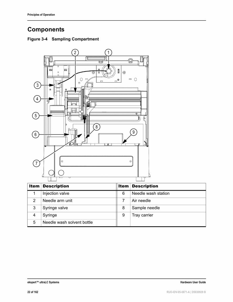
Components
Figure 3-4 Sampling Compartment
Item Description Item Description1 Injection valve 6 Needle wash station
2 Needle arm unit 7 Air needle
3 Syringe valve 8 Sample needle
4 Syringe 9 Tray carrier
5 Needle wash solvent bottle
4
2 1
5
6
3
7
98
ekspert™ ultraLC Systems Hardware User Guide
22 of 162 RUO-IDV-05-0871-A | D5030929 B
Principles of Operation
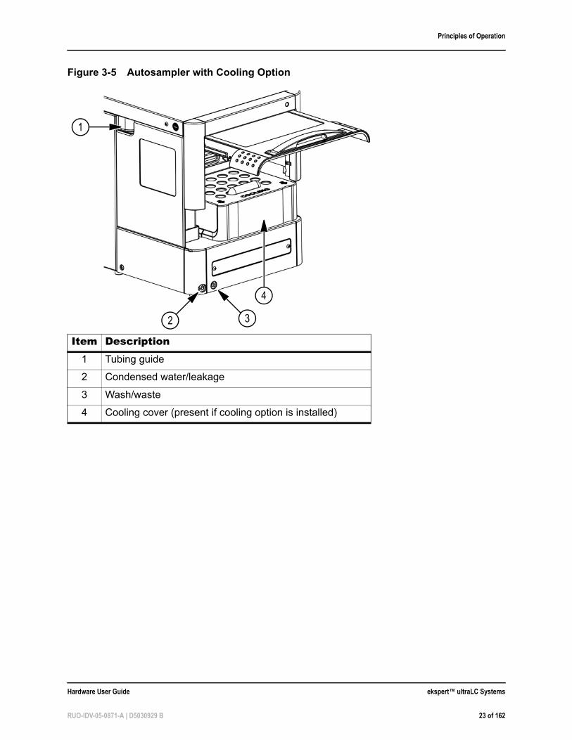
Figure 3-5 Autosampler with Cooling Option
Item Description1 Tubing guide
2 Condensed water/leakage
3 Wash/waste
4 Cooling cover (present if cooling option is installed)
4
3
1
2
Hardware User Guide ekspert™ ultraLC Systems
RUO-IDV-05-0871-A | D5030929 B 23 of 162
Principles of Operation
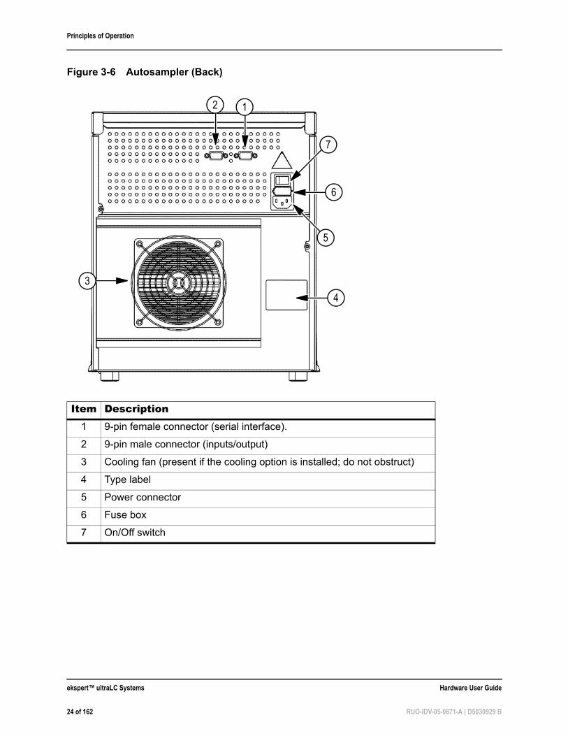
Figure 3-6 Autosampler (Back)
Item Description1 9-pin female connector (serial interface).
2 9-pin male connector (inputs/output)
3 Cooling fan (present if the cooling option is installed; do not obstruct)
4 Type label
5 Power connector
6 Fuse box
7 On/Off switch
5
6
2
3
7
1
4
ekspert™ ultraLC Systems Hardware User Guide
24 of 162 RUO-IDV-05-0871-A | D5030929 B
Principles of Operation
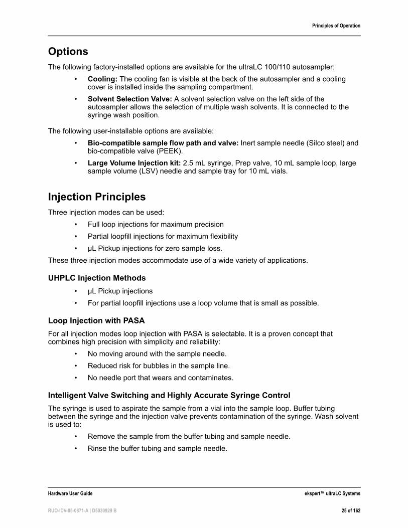
OptionsThe following factory-installed options are available for the ultraLC 100/110 autosampler:
• Cooling: The cooling fan is visible at the back of the autosampler and a cooling cover is installed inside the sampling compartment.
• Solvent Selection Valve: A solvent selection valve on the left side of the autosampler allows the selection of multiple wash solvents. It is connected to the syringe wash position.
The following user-installable options are available:
• Bio-compatible sample flow path and valve: Inert sample needle (Silco steel) and bio-compatible valve (PEEK).
• Large Volume Injection kit: 2.5 mL syringe, Prep valve, 10 mL sample loop, large sample volume (LSV) needle and sample tray for 10 mL vials.
Injection PrinciplesThree injection modes can be used:
• Full loop injections for maximum precision
• Partial loopfill injections for maximum flexibility
• µL Pickup injections for zero sample loss.
These three injection modes accommodate use of a wide variety of applications.
UHPLC Injection Methods
• µL Pickup injections
• For partial loopfill injections use a loop volume that is small as possible.
Loop Injection with PASA
For all injection modes loop injection with PASA is selectable. It is a proven concept that combines high precision with simplicity and reliability:
• No moving around with the sample needle.
• Reduced risk for bubbles in the sample line.
• No needle port that wears and contaminates.
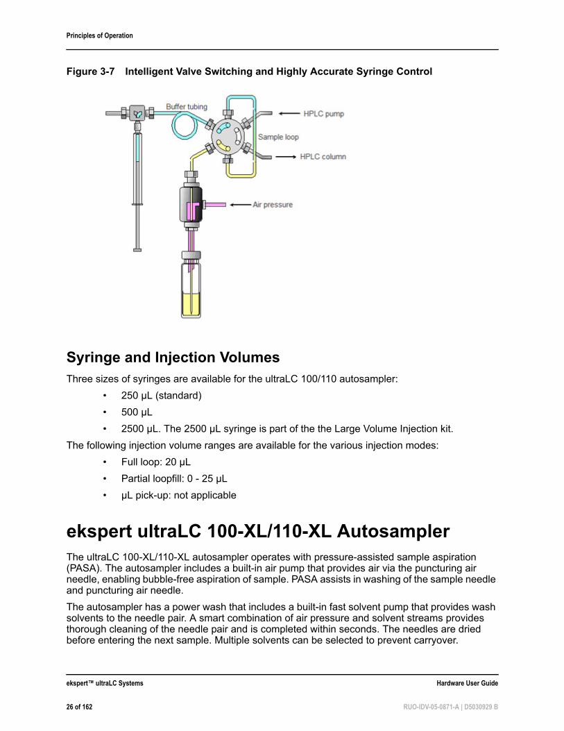
Intelligent Valve Switching and Highly Accurate Syringe Control
The syringe is used to aspirate the sample from a vial into the sample loop. Buffer tubing between the syringe and the injection valve prevents contamination of the syringe. Wash solvent is used to:
• Remove the sample from the buffer tubing and sample needle.
• Rinse the buffer tubing and sample needle.
Hardware User Guide ekspert™ ultraLC Systems
RUO-IDV-05-0871-A | D5030929 B 25 of 162
Principles of Operation
Syringe and Injection VolumesThree sizes of syringes are available for the ultraLC 100/110 autosampler:
• 250 µL (standard)
• 500 µL
• 2500 µL. The 2500 µL syringe is part of the the Large Volume Injection kit.
The following injection volume ranges are available for the various injection modes:
• Full loop: 20 µL
• Partial loopfill: 0 - 25 µL
• µL pick-up: not applicable
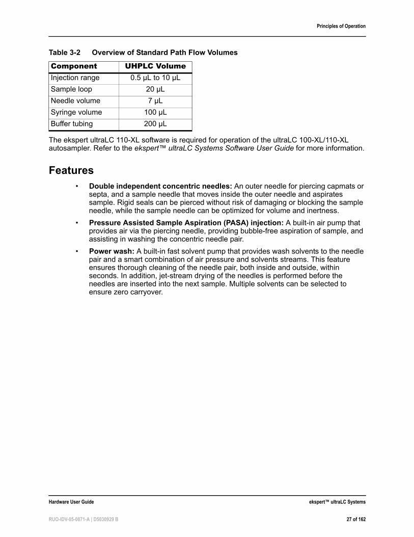
ekspert ultraLC 100-XL/110-XL AutosamplerThe ultraLC 100-XL/110-XL autosampler operates with pressure-assisted sample aspiration (PASA). The autosampler includes a built-in air pump that provides air via the puncturing air needle, enabling bubble-free aspiration of sample. PASA assists in washing of the sample needle and puncturing air needle.
The autosampler has a power wash that includes a built-in fast solvent pump that provides wash solvents to the needle pair. A smart combination of air pressure and solvent streams provides thorough cleaning of the needle pair and is completed within seconds. The needles are dried before entering the next sample. Multiple solvents can be selected to prevent carryover.
Figure 3-7 Intelligent Valve Switching and Highly Accurate Syringe Control
ekspert™ ultraLC Systems Hardware User Guide
26 of 162 RUO-IDV-05-0871-A | D5030929 B
Principles of Operation
The ekspert ultraLC 110-XL software is required for operation of the ultraLC 100-XL/110-XL autosampler. Refer to the ekspert™ ultraLC Systems Software User Guide for more information.
Features• Double independent concentric needles: An outer needle for piercing capmats or
septa, and a sample needle that moves inside the outer needle and aspirates sample. Rigid seals can be pierced without risk of damaging or blocking the sample needle, while the sample needle can be optimized for volume and inertness.
• Pressure Assisted Sample Aspiration (PASA) injection: A built-in air pump that provides air via the piercing needle, providing bubble-free aspiration of sample, and assisting in washing the concentric needle pair.
• Power wash: A built-in fast solvent pump that provides wash solvents to the needle pair and a smart combination of air pressure and solvents streams. This feature ensures thorough cleaning of the needle pair, both inside and outside, within seconds. In addition, jet-stream drying of the needles is performed before the needles are inserted into the next sample. Multiple solvents can be selected to ensure zero carryover.
Table 3-2 Overview of Standard Path Flow Volumes
Component UHPLC VolumeInjection range 0.5 µL to 10 µL
Sample loop 20 µL
Needle volume 7 µL
Syringe volume 100 µL
Buffer tubing 200 µL
Hardware User Guide ekspert™ ultraLC Systems
RUO-IDV-05-0871-A | D5030929 B 27 of 162
Principles of Operation
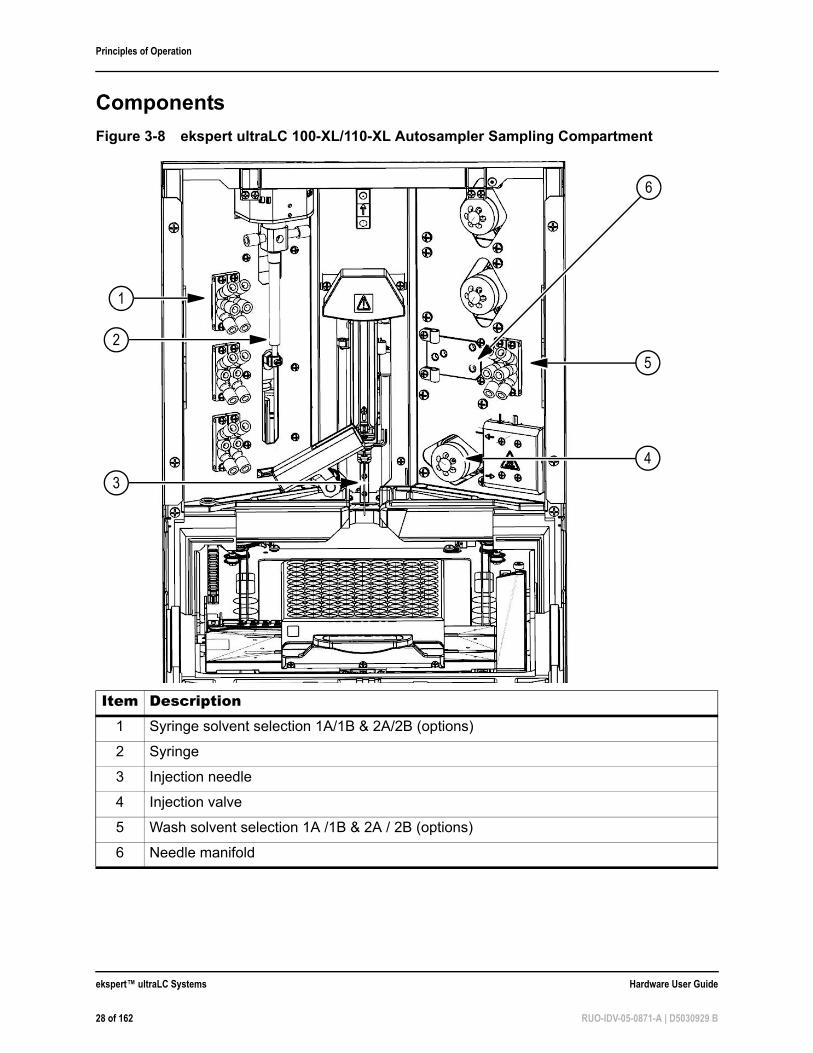
Components
Figure 3-8 ekspert ultraLC 100-XL/110-XL Autosampler Sampling Compartment
Item Description1 Syringe solvent selection 1A/1B & 2A/2B (options)
2 Syringe
3 Injection needle
4 Injection valve
5 Wash solvent selection 1A /1B & 2A / 2B (options)
6 Needle manifold
5
1
2
3
4
6
ekspert™ ultraLC Systems Hardware User Guide
28 of 162 RUO-IDV-05-0871-A | D5030929 B
Principles of Operation
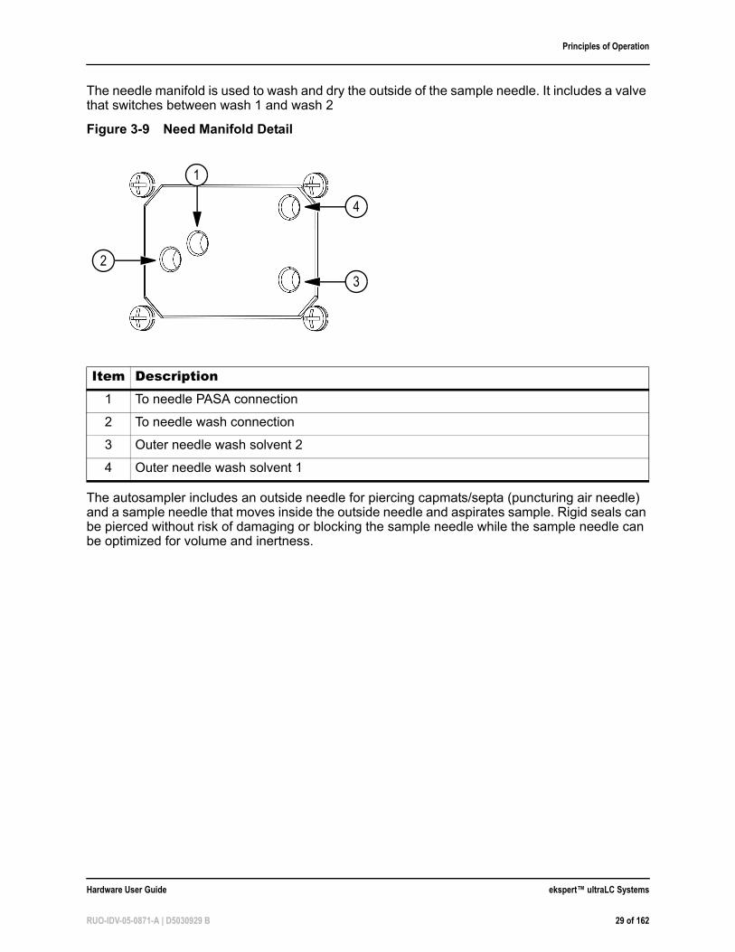
The needle manifold is used to wash and dry the outside of the sample needle. It includes a valve that switches between wash 1 and wash 2
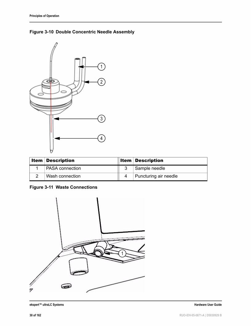
The autosampler includes an outside needle for piercing capmats/septa (puncturing air needle) and a sample needle that moves inside the outside needle and aspirates sample. Rigid seals can be pierced without risk of damaging or blocking the sample needle while the sample needle can be optimized for volume and inertness.
Figure 3-9 Need Manifold Detail
Item Description1 To needle PASA connection
2 To needle wash connection
3 Outer needle wash solvent 2
4 Outer needle wash solvent 1
4
3
1
2
Hardware User Guide ekspert™ ultraLC Systems
RUO-IDV-05-0871-A | D5030929 B 29 of 162
Principles of Operation
Figure 3-10 Double Concentric Needle Assembly
Item Description Item Description1 PASA connection 3 Sample needle
2 Wash connection 4 Puncturing air needle
Figure 3-11 Waste Connections
1
2
3
4
1
ekspert™ ultraLC Systems Hardware User Guide
30 of 162 RUO-IDV-05-0871-A | D5030929 B
Principles of Operation
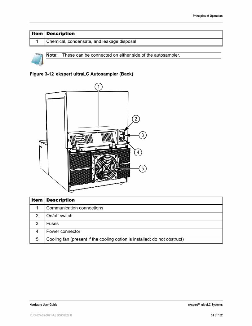
Item Description1 Chemical, condensate, and leakage disposal
Note: These can be connected on either side of the autosampler.
Figure 3-12 ekspert ultraLC Autosampler (Back)
Item Description1 Communication connections
2 On/off switch
3 Fuses
4 Power connector
5 Cooling fan (present if the cooling option is installed; do not obstruct)
4
3
2
5
1
Hardware User Guide ekspert™ ultraLC Systems
RUO-IDV-05-0871-A | D5030929 B 31 of 162
Principles of Operation
Well Plate Types and Adapters
Caution: Potential Cross Contamination: Do not fill vials or wells to the edge. Sample will be forced into the puncturing air needle, risking cross-contamination of samples and soiling the needles.
Caution: Potential Sensitivity Change: Do not use uncapped vials as the performance of the injections might no longer meet the specifications for precision. It is important that seals and capmats are airtight to prevent air bubbles from forming and to prevent evaporation of volatile samples. Do not re-use a sample vial frequently without replacing the cap or septum.
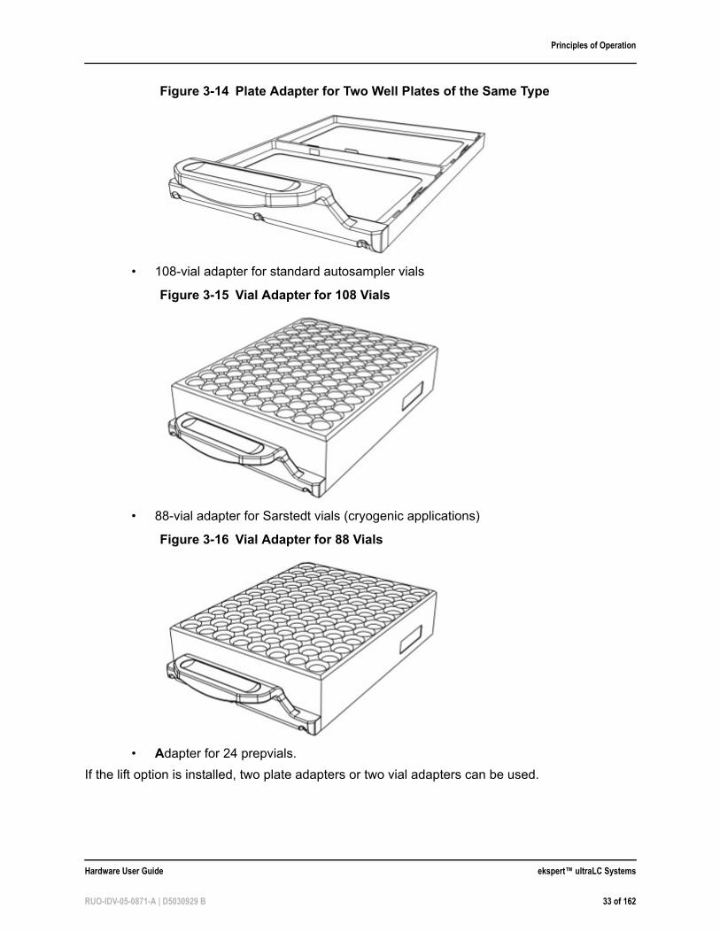
The autosampler accommodates the use of well plates and vials through separate adapters. The plate adapter supports two standard well plates of the same type, high or low. Three types of vial adapters are available: 88 Sarstedt vials, 108 standard 2 mL vials, and 24 prep vials. Two plate adapters or two vial adapters can be used.
The following well plate types and adapters can be used with the autosampler:
• Two micro titre plates of the same type (96-well and 384-well; low, medium and deep well). Two plates can be placed on the plate adapter that is supplied with the autosampler:
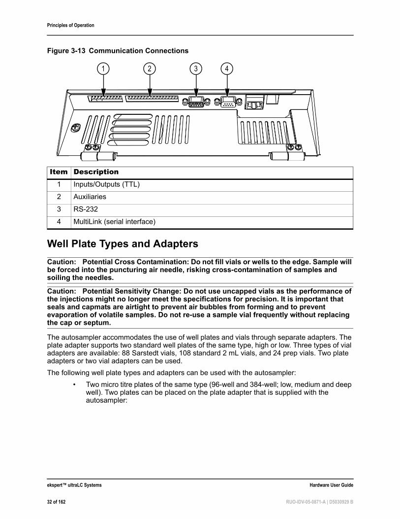
Figure 3-13 Communication Connections
Item Description1 Inputs/Outputs (TTL)
2 Auxiliaries
3 RS-232
4 MultiLink (serial interface)
1 2 3 4
ekspert™ ultraLC Systems Hardware User Guide
32 of 162 RUO-IDV-05-0871-A | D5030929 B
Principles of Operation
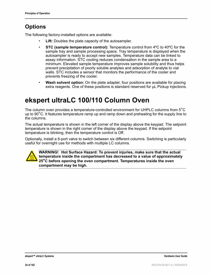
• 108-vial adapter for standard autosampler vials
• 88-vial adapter for Sarstedt vials (cryogenic applications)
• Adapter for 24 prepvials.
If the lift option is installed, two plate adapters or two vial adapters can be used.
Figure 3-14 Plate Adapter for Two Well Plates of the Same Type
Figure 3-15 Vial Adapter for 108 Vials
Figure 3-16 Vial Adapter for 88 Vials
Hardware User Guide ekspert™ ultraLC Systems
RUO-IDV-05-0871-A | D5030929 B 33 of 162
Principles of Operation
OptionsThe following factory-installed options are available:
• Lift: Doubles the plate capacity of the autosampler.
• STC (sample temperature control): Temperature control from 4ºC to 40ºC for the sample tray and sample processing space. Tray temperature is displayed when the autosampler is ready to accept new samples. Temperature data can be linked to assay information. STC cooling reduces condensation in the sample area to a minimum. Elevated sample temperature improves sample solubility and thus helps prevent precipitation of poorly soluble analytes and adsorption of analyte to vial walls. STC includes a sensor that monitors the performance of the cooler and prevents freezing of the cooler.
• Wash solvent option: On the plate adapter, four positions are available for placing extra reagents. One of these positions is standard reserved for µL Pickup injections.
ekspert ultraLC 100/110 Column OvenThe column oven provides a temperature-controlled environment for UHPLC columns from 5°C up to 90°C. It features temperature ramp up and ramp down and preheating for the supply line to the columns.
The actual temperature is shown in the left corner of the display above the keypad. The setpoint temperature is shown in the right corner of the display above the keypad. If the setpoint temperature is blinking, then the temperature control is Off.
Optionally, install a 6-port valve to switch between six different columns. Switching is particularly useful for overnight use for methods with multiple LC columns.
WARNING! Hot Surface Hazard: To prevent injuries, make sure that the actual temperature inside the compartment has decreased to a value of approximately 25°C before opening the oven compartment. Temperatures inside the oven compartment may be high.
ekspert™ ultraLC Systems Hardware User Guide
34 of 162 RUO-IDV-05-0871-A | D5030929 B
Principles of Operation
Components
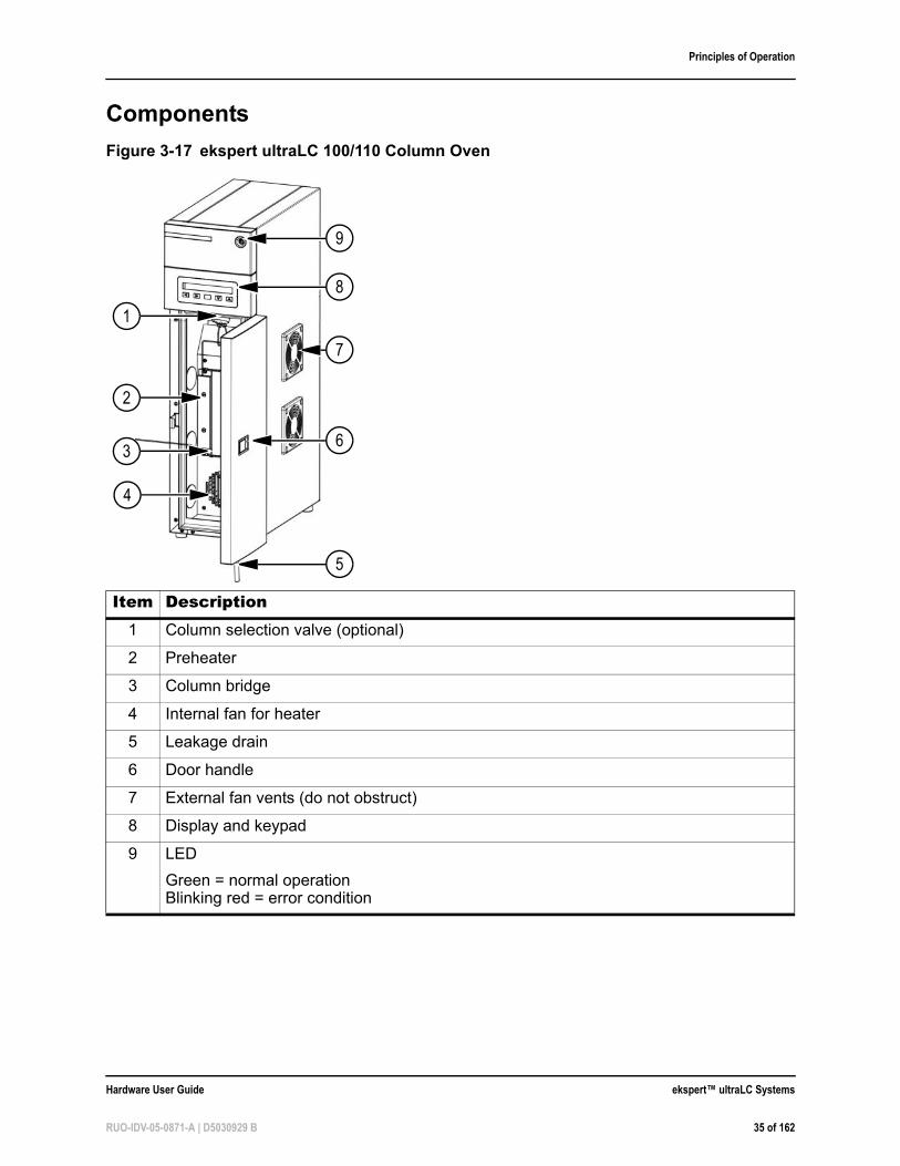
Figure 3-17 ekspert ultraLC 100/110 Column Oven
Item Description1 Column selection valve (optional)
2 Preheater
3 Column bridge
4 Internal fan for heater
5 Leakage drain
6 Door handle
7 External fan vents (do not obstruct)
8 Display and keypad
9 LED
Green = normal operationBlinking red = error condition
9
1
8
7
6
5
2
3
4
Hardware User Guide ekspert™ ultraLC Systems
RUO-IDV-05-0871-A | D5030929 B 35 of 162
Principles of Operation
SensorsA vapor sensor and temperature sensor are located inside the column oven compartment, at the top of the compartment. The temperature sensor detects the temperature of the compartment and displays it in the ekspert ultraLC software. Refer to Set the Vapor Alarm Sensitivity on page 184.
When a leak occurs and the mobile phase (with organic solvents) is vaporized, a leak sensor detects the gas and an alarm is displayed on the keypad. The sensor detects all commonly used organic solvents in the LC mobile phases (for example, methanol, acetonitrile, THF, acetonitrile). These solvents are volatile when heated in the column oven.
Column Oven ControlsThe column oven can be controlled in one of two ways:
• Software control: Control the column oven with the ekspert ultraLC software. Refer to the ekspert™ ultraLC Systems Software User Guide.
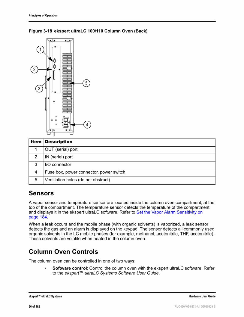
Figure 3-18 ekspert ultraLC 100/110 Column Oven (Back)
Item Description1 OUT (serial) port
2 IN (serial) port
3 I/O connector
4 Fuse box, power connector, power switch
5 Ventilation holes (do not obstruct)
5
2
1
3
4
ekspert™ ultraLC Systems Hardware User Guide
36 of 162 RUO-IDV-05-0871-A | D5030929 B
Principles of Operation
• Keypad control: Use the keypad and display on the column oven to manually control the column oven. During acquisition, the keypad is disabled. Refer to ekspert™ ultraLC 100/110 Column Oven Keypad on page 157.
Options• Column switching valve: This factory-installed option supports a maximum of 6
different LC columns.
• Cooling option
Tips for Handling Samples• Standard vials, as well as the conical vials, can best be filled by means of a narrow-
end pipette to allow air to escape when filling the vial.
• Filtering the eluent with a 0.2 µm filter will considerably reduce the risk of clogging. Filter samples to further reduce the risk of clogging. Confirm that the appropriate filter material for the type of sample is being used.
• Inspect the seal after crimping. If the cap can be turned easily, then the seal is not air-tight (adjust the handcrimper).
• The manufacturer recommends use of the following seal types:
• For standard (low) well plates: Sealing tape
• For deep well plates: Pierceable capmats (Pre-slit or silicon) or sealing tape
• For vials: Standard septa
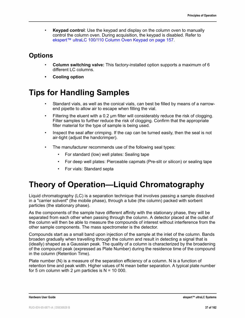
Theory of Operation—Liquid ChromatographyLiquid chromatography (LC) is a separation technique that involves passing a sample dissolved in a "carrier solvent" (the mobile phase), through a tube (the column) packed with sorbent particles (the stationary phase).
As the components of the sample have different affinity with the stationary phase, they will be separated from each other when passing through the column. A detector placed at the outlet of the column will then be able to measure the compounds of interest without interference from the other sample components. The mass spectrometer is the detector.
Compounds start as a small band upon injection of the sample at the inlet of the column. Bands broaden gradually when travelling through the column and result in detecting a signal that is (ideally) shaped as a Gaussian peak. The quality of a column is characterized by the broadening of the compound peak (expressed as Plate Number) during the residence time of the compound in the column (Retention Time).
Plate number (N) is a measure of the separation efficiency of a column. N is a function of retention time and peak width. Higher values of N mean better separation. A typical plate number for 5 cm column with 2 µm particles is N = 10 000.
Hardware User Guide ekspert™ ultraLC Systems
RUO-IDV-05-0871-A | D5030929 B 37 of 162
Principles of Operation
Retention time (RT) is the time it takes for a compound to travel through the column and is measured as time between moment of sample injection and moment of compound detection at peak summit. Shorter retention times enable higher sample throughput.
Injection Mode OverviewInjection modes can be selected for different reasons:
• Full Loop injections for maximum reproducibility
• Partial Loop injections for maximum flexibility
• µL Pickup injections for zero sample loss
For all injection modes, there is loop injection with Pressure-Assisted Sample Aspiration (PASA). The syringe is used to aspirate the sample from a vial into the sample loop. Buffer tubing between the syringe and the injection valve prevents contamination of the syringe. Wash solvent is used to:
• Remove the sample from the buffer tubing and sample needle
• Rinse the buffer tubing and sample needle
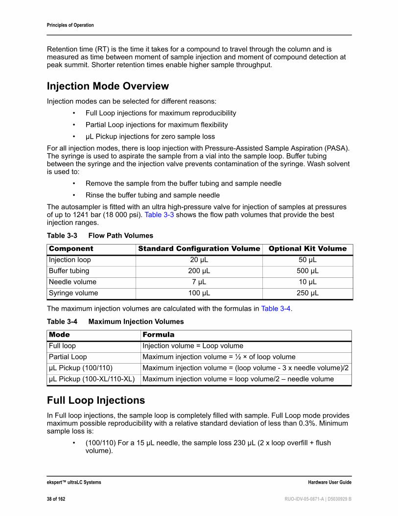
The autosampler is fitted with an ultra high-pressure valve for injection of samples at pressures of up to 1241 bar (18 000 psi). Table 3-3 shows the flow path volumes that provide the best injection ranges.
The maximum injection volumes are calculated with the formulas in Table 3-4.
Full Loop InjectionsIn Full loop injections, the sample loop is completely filled with sample. Full Loop mode provides maximum possible reproducibility with a relative standard deviation of less than 0.3%. Minimum sample loss is:
• (100/110) For a 15 µL needle, the sample loss 230 µL (2 x loop overfill + flush volume).
Table 3-3 Flow Path Volumes
Component Standard Configuration Volume Optional Kit VolumeInjection loop 20 µL 50 µL
Buffer tubing 200 µL 500 µL
Needle volume 7 µL 10 µL
Syringe volume 100 µL 250 µL
Table 3-4 Maximum Injection Volumes
Mode FormulaFull loop Injection volume = Loop volume
Partial Loop Maximum injection volume = ½ × of loop volume
µL Pickup (100/110) Maximum injection volume = (loop volume - 3 x needle volume)/2
µL Pickup (100-XL/110-XL) Maximum injection volume = loop volume/2 – needle volume
ekspert™ ultraLC Systems Hardware User Guide
38 of 162 RUO-IDV-05-0871-A | D5030929 B
Principles of Operation
• (100-XL/110-XL) For a 20 µL loop with a 7 µL needle, the sample loss (in addition to the injection volume) is equal to 81 µL (3 × loop volume overfill plus 3 × needle volume as flush volume is recommended). The flush volume value is editable in the ekspert ultraLC software.
Switching Sequence
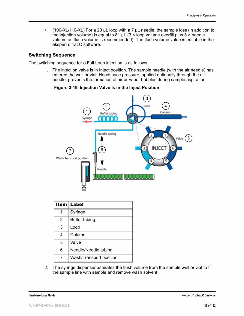
The switching sequence for a Full Loop injection is as follows.
1. The injection valve is in Inject position. The sample needle (with the air needle) has entered the well or vial. Headspace pressure, applied optionally through the air needle, prevents the formation of air or vapor bubbles during sample aspiration.
2. The syringe dispenser aspirates the flush volume from the sample well or vial to fill the sample line with sample and remove wash solvent.
Figure 3-19 Injection Valve Is in the Inject Position
Item Label1 Syringe
2 Buffer tubing
3 Loop
4 Column
5 Valve
6 Needle/Needle tubing
7 Wash/Transport position
12
3
4
5
67
Hardware User Guide ekspert™ ultraLC Systems
RUO-IDV-05-0871-A | D5030929 B 39 of 162
Principles of Operation
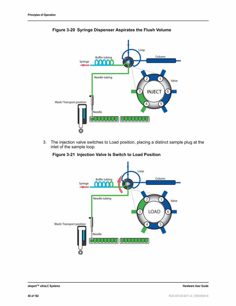
3. The injection valve switches to Load position, placing a distinct sample plug at the inlet of the sample loop.
Figure 3-20 Syringe Dispenser Aspirates the Flush Volume
Figure 3-21 Injection Valve Is Switch to Load Position
ekspert™ ultraLC Systems Hardware User Guide
40 of 162 RUO-IDV-05-0871-A | D5030929 B
Principles of Operation
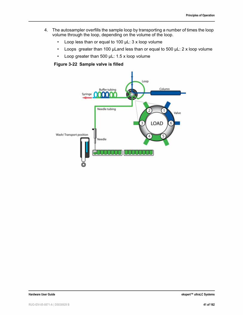
4. The autosampler overfills the sample loop by transporting a number of times the loop volume through the loop, depending on the volume of the loop.
• Loop less than or equal to 100 µL: 3 x loop volume
• Loops greater than 100 µLand less than or equal to 500 µL: 2 x loop volume
• Loop greater than 500 µL: 1.5 x loop volume
Figure 3-22 Sample valve is filled
Hardware User Guide ekspert™ ultraLC Systems
RUO-IDV-05-0871-A | D5030929 B 41 of 162
Principles of Operation
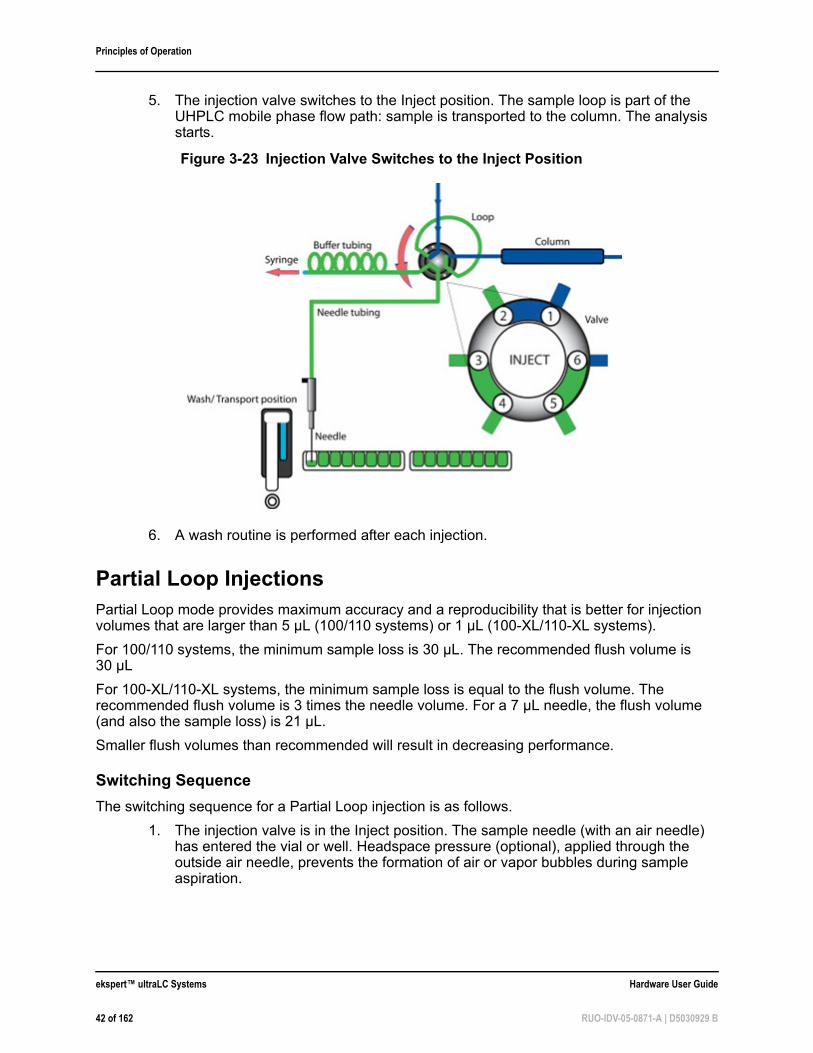
5. The injection valve switches to the Inject position. The sample loop is part of the UHPLC mobile phase flow path: sample is transported to the column. The analysis starts.
6. A wash routine is performed after each injection.
Partial Loop InjectionsPartial Loop mode provides maximum accuracy and a reproducibility that is better for injection volumes that are larger than 5 µL (100/110 systems) or 1 µL (100-XL/110-XL systems).
For 100/110 systems, the minimum sample loss is 30 µL. The recommended flush volume is 30 µL
For 100-XL/110-XL systems, the minimum sample loss is equal to the flush volume. The recommended flush volume is 3 times the needle volume. For a 7 µL needle, the flush volume (and also the sample loss) is 21 µL.
Smaller flush volumes than recommended will result in decreasing performance.
Switching Sequence
The switching sequence for a Partial Loop injection is as follows.
1. The injection valve is in the Inject position. The sample needle (with an air needle) has entered the vial or well. Headspace pressure (optional), applied through the outside air needle, prevents the formation of air or vapor bubbles during sample aspiration.
Figure 3-23 Injection Valve Switches to the Inject Position
ekspert™ ultraLC Systems Hardware User Guide
42 of 162 RUO-IDV-05-0871-A | D5030929 B
Principles of Operation
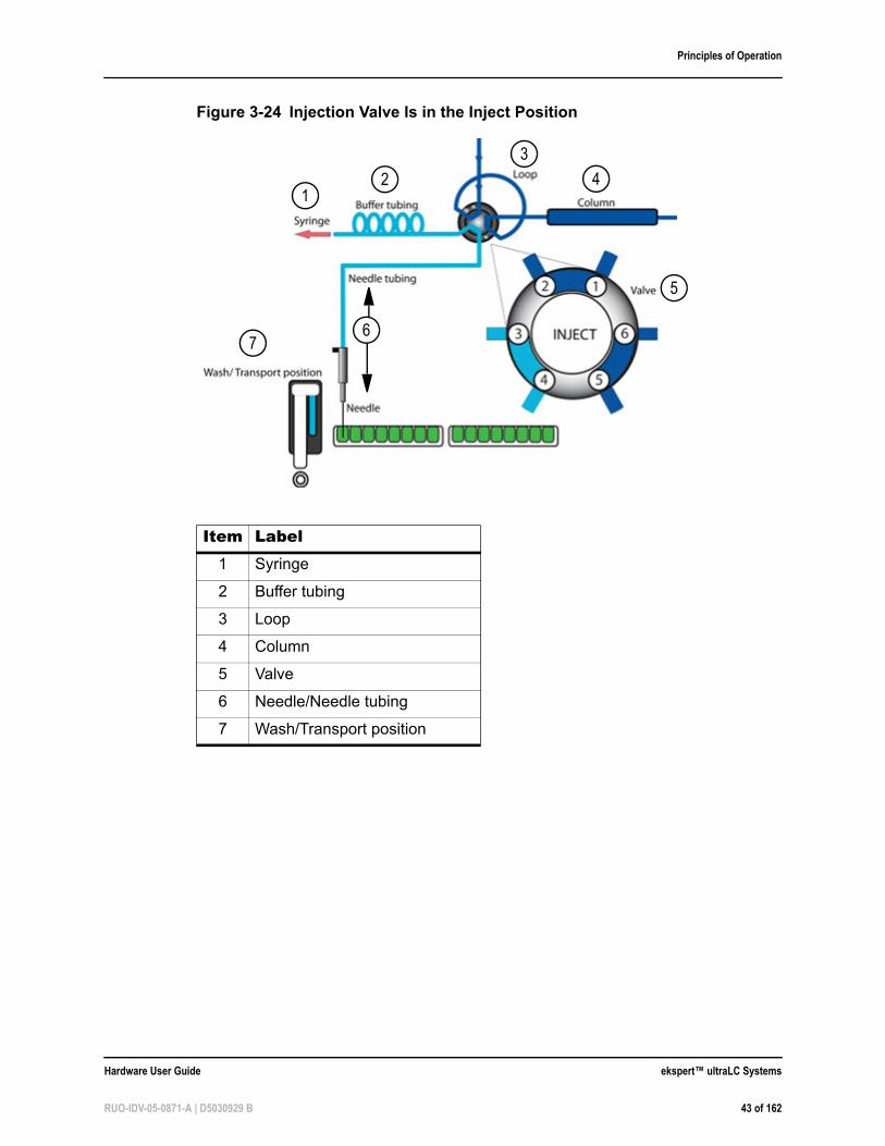
Figure 3-24 Injection Valve Is in the Inject Position
Item Label1 Syringe
2 Buffer tubing
3 Loop
4 Column
5 Valve
6 Needle/Needle tubing
7 Wash/Transport position
12
3
4
5
76
Hardware User Guide ekspert™ ultraLC Systems
RUO-IDV-05-0871-A | D5030929 B 43 of 162
Principles of Operation
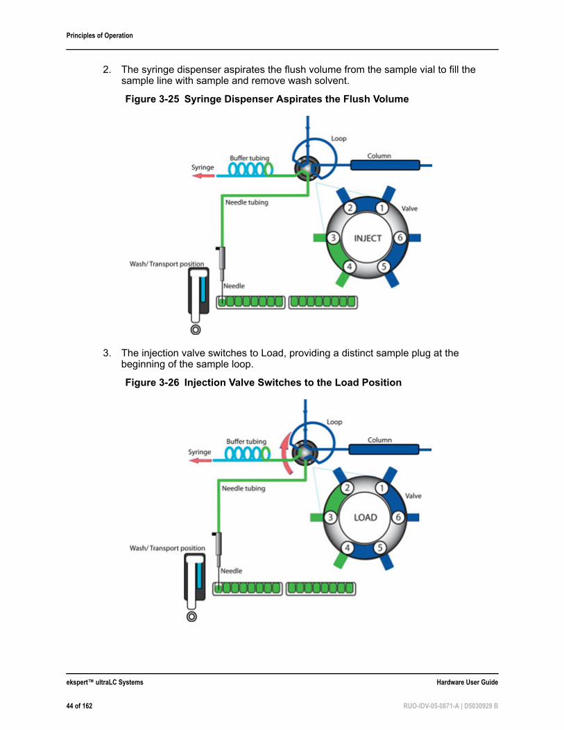
2. The syringe dispenser aspirates the flush volume from the sample vial to fill the sample line with sample and remove wash solvent.
3. The injection valve switches to Load, providing a distinct sample plug at the beginning of the sample loop.
Figure 3-25 Syringe Dispenser Aspirates the Flush Volume
Figure 3-26 Injection Valve Switches to the Load Position
ekspert™ ultraLC Systems Hardware User Guide
44 of 162 RUO-IDV-05-0871-A | D5030929 B
Principles of Operation
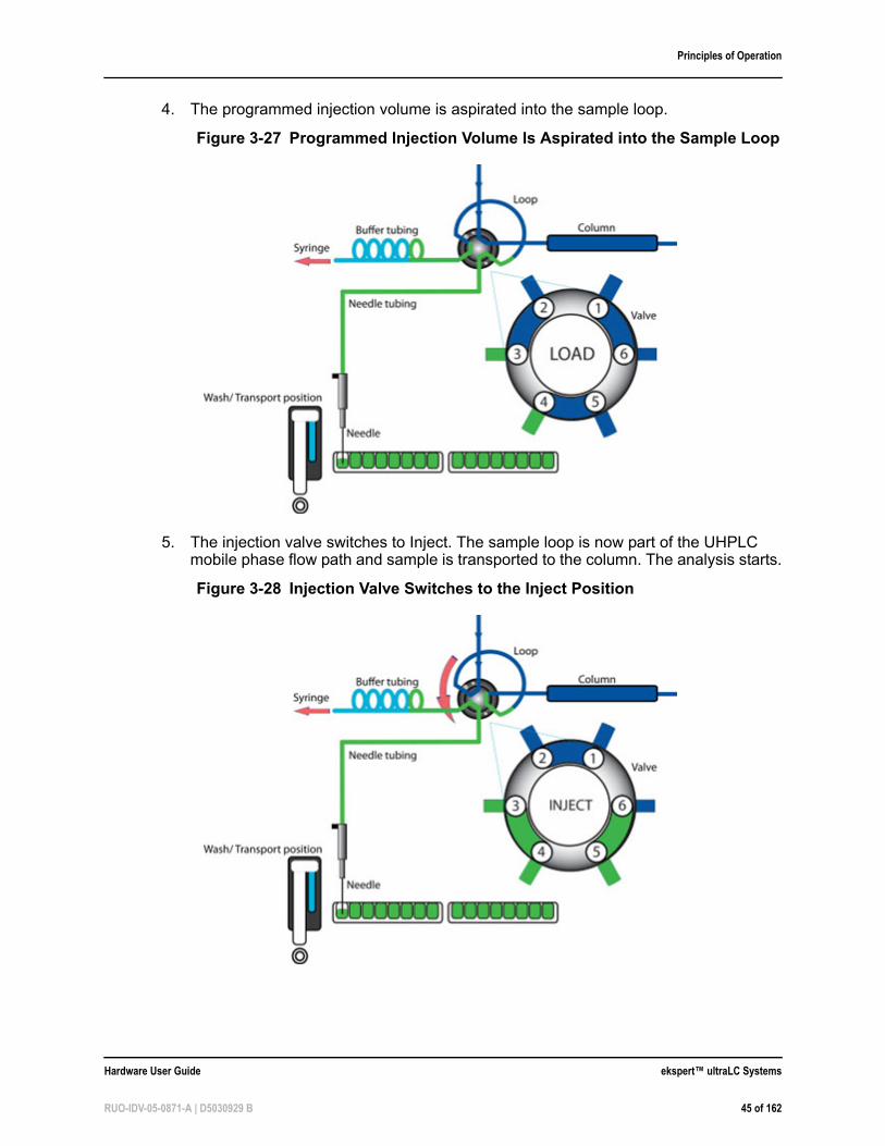
4. The programmed injection volume is aspirated into the sample loop.
5. The injection valve switches to Inject. The sample loop is now part of the UHPLC mobile phase flow path and sample is transported to the column. The analysis starts.
Figure 3-27 Programmed Injection Volume Is Aspirated into the Sample Loop
Figure 3-28 Injection Valve Switches to the Inject Position
Hardware User Guide ekspert™ ultraLC Systems
RUO-IDV-05-0871-A | D5030929 B 45 of 162
Principles of Operation
µL PickupµL Pickup mode provides maximum accuracy (like Partial Loop mode), but slightly lower reproducibility of RSD, that is greater than 1% for injection volumes that are greater than 5 µL (100/110 systems) or 1 µL (100-XL/110-XL systems).
µL Pickup injection mode is used for limited sample volumes as it makes sure that the entire sample volume that is aspirated is injected. In addition, tapered vials or inserts (for vials or well plates) can be used to make sure that the autosampler can acquire any volume that is available. Only a small amount of the sample is left in the sample container.
µL Pickup injection enables the user to inject sample with zero sample loss. This injection mode uses transport liquid to draw the sample into the sample loop. The composition of the transport liquid composition has a significant impact on method development. However, matching the transport liquid to the initial column equilibration or sample solvent composition is a good starting point.
Significant amounts of transport solvent are present in the loop at injection. The impact of the transport solvent composition can be an important consideration in method development. The manufacturer recommends, for reversed phase LC methods, that aqueous solvents be used. Matching the transport solvent to initial column equilibration and sample solvent composition is considered a good starting point.
When sample is drawn into the loop, the front and the end of the sample plug become dilute because of the laminar (parabolic) flow profile. The amount of dilution depends on the loop and needle size. Therefore, the maximum injection volume for this mode is limited to the half of the needle volume, minus the needle volume.
Example Injection Calculation
In an autosampler configuration (UHPLC) with a needle volume of 7 µL and an installed loop volume of 20 µL, a transport volume of 16 µL is required to make sure that 1 µL sample is completely drawn into the loop.
A transport volume that is too high draws the liquid front of the sample plug out of the loop, resulting in sample loss. When a method is developed, verify the accuracy of the method (if a correct injection volume is used). The transport volume cannot be changed.
The standard configuration with a 20 µL loop allows a maximum injection volume of 3 µL. When a loop of 50 µL is installed (this requires a larger-size syringe, buffer tubing, and sample needle), the maximum injection volume is 15 µL.
Note: It might be necessary to optimize the height of the sample needle to aspirate available sample from the various vial types.
Note: Because the sample is between two plugs of transport liquid, care must be taken to properly configure sample volume, installed needle volume, installed loop volume and transport volume.
Tip! The use of 100% water (even with acid) can allow microbial growth in the solvent reservoir. The manufacturer recommends washing the bottle and changing the solvent regularly when using solvents favorable to the growth of organisms.
ekspert™ ultraLC Systems Hardware User Guide
46 of 162 RUO-IDV-05-0871-A | D5030929 B
Principles of Operation
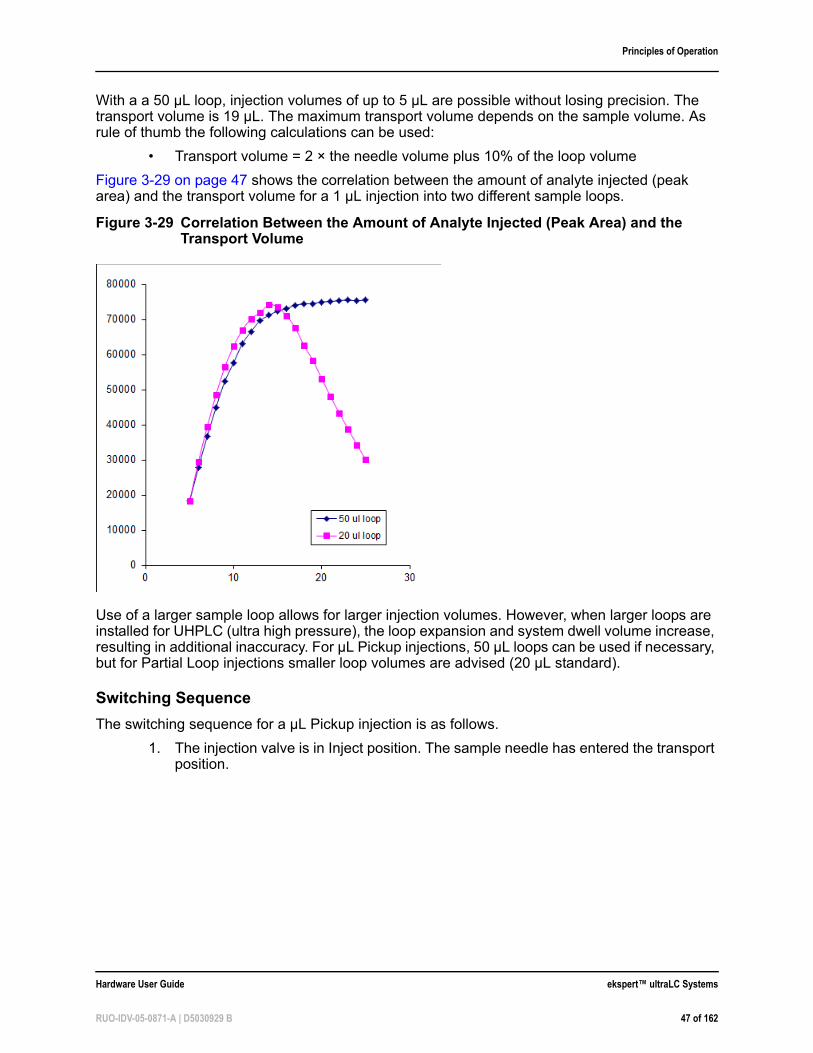
With a a 50 µL loop, injection volumes of up to 5 µL are possible without losing precision. The transport volume is 19 µL. The maximum transport volume depends on the sample volume. As rule of thumb the following calculations can be used:
• Transport volume = 2 × the needle volume plus 10% of the loop volume
Figure 3-29 on page 47 shows the correlation between the amount of analyte injected (peak area) and the transport volume for a 1 µL injection into two different sample loops.
Use of a larger sample loop allows for larger injection volumes. However, when larger loops are installed for UHPLC (ultra high pressure), the loop expansion and system dwell volume increase, resulting in additional inaccuracy. For µL Pickup injections, 50 µL loops can be used if necessary, but for Partial Loop injections smaller loop volumes are advised (20 µL standard).
Switching Sequence
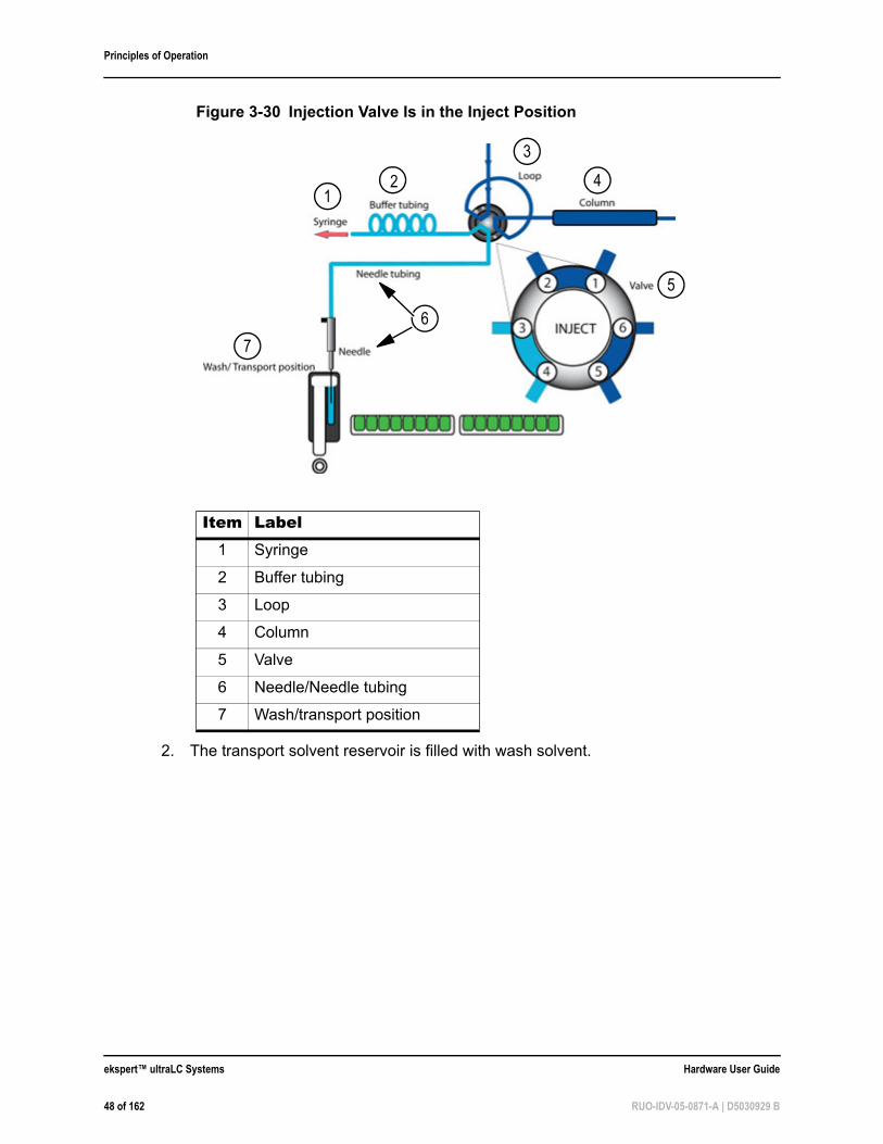
The switching sequence for a µL Pickup injection is as follows.
1. The injection valve is in Inject position. The sample needle has entered the transport position.
Figure 3-29 Correlation Between the Amount of Analyte Injected (Peak Area) and the Transport Volume
Hardware User Guide ekspert™ ultraLC Systems
RUO-IDV-05-0871-A | D5030929 B 47 of 162
Principles of Operation
2. The transport solvent reservoir is filled with wash solvent.
Figure 3-30 Injection Valve Is in the Inject Position
Item Label1 Syringe
2 Buffer tubing
3 Loop
4 Column
5 Valve
6 Needle/Needle tubing
7 Wash/transport position
2
3
41
7
5
6
ekspert™ ultraLC Systems Hardware User Guide
48 of 162 RUO-IDV-05-0871-A | D5030929 B
Principles of Operation
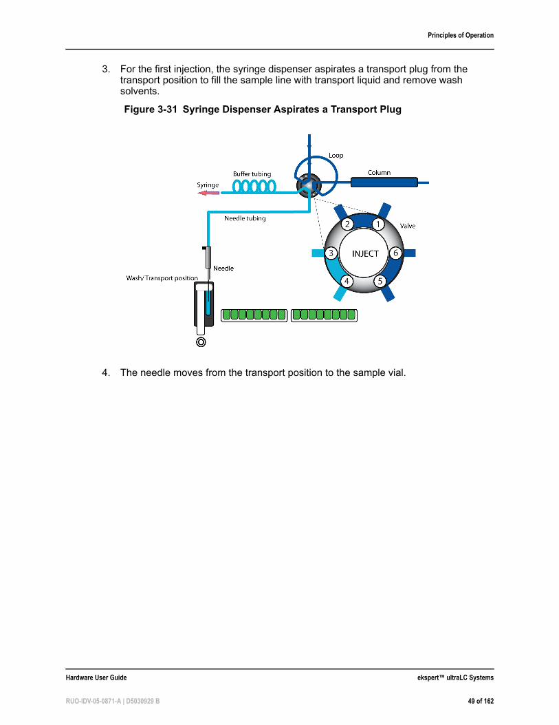
3. For the first injection, the syringe dispenser aspirates a transport plug from the transport position to fill the sample line with transport liquid and remove wash solvents.
4. The needle moves from the transport position to the sample vial.
Figure 3-31 Syringe Dispenser Aspirates a Transport Plug
Hardware User Guide ekspert™ ultraLC Systems
RUO-IDV-05-0871-A | D5030929 B 49 of 162
Principles of Operation
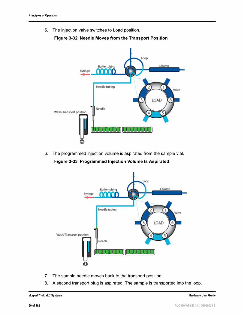
5. The injection valve switches to Load position.
6. The programmed injection volume is aspirated from the sample vial.
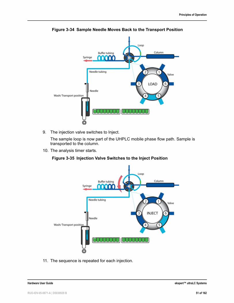
7. The sample needle moves back to the transport position.
8. A second transport plug is aspirated. The sample is transported into the loop.
Figure 3-32 Needle Moves from the Transport Position
Figure 3-33 Programmed Injection Volume Is Aspirated
ekspert™ ultraLC Systems Hardware User Guide
50 of 162 RUO-IDV-05-0871-A | D5030929 B
Principles of Operation
9. The injection valve switches to Inject.
The sample loop is now part of the UHPLC mobile phase flow path. Sample is transported to the column.
10. The analysis timer starts.
11. The sequence is repeated for each injection.
Figure 3-34 Sample Needle Moves Back to the Transport Position
Figure 3-35 Injection Valve Switches to the Inject Position
Hardware User Guide ekspert™ ultraLC Systems
RUO-IDV-05-0871-A | D5030929 B 51 of 162
Principles of Operation
Viscous SamplesWhen working with viscous samples:
• Use Full Loop injection or Partial Loop injection mode.
• Use capped vials and enable PASA during LC method creation.
• Lower the aspirate sample speed to prevent high underpressure and evaporation during sample aspiration, if necessary.
• Use default values for commonly used solvents and sample viscosities.
• For high viscosity samples like blood or plasma, a 10 µL needle is available that allows the injection of these types of samples.
• For 100-XL and 110-XL systems with the sample temperature control option, increase the temperature in the sample compartment to make samples less viscous.
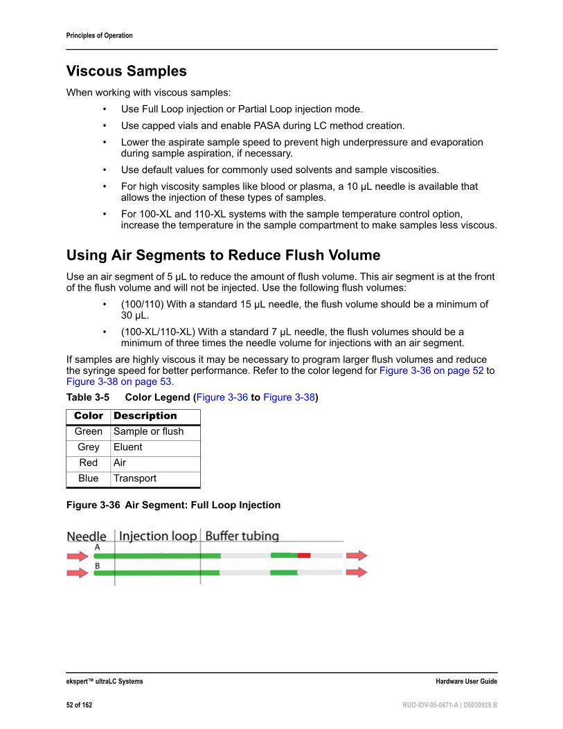
Using Air Segments to Reduce Flush VolumeUse an air segment of 5 µL to reduce the amount of flush volume. This air segment is at the front of the flush volume and will not be injected. Use the following flush volumes:
• (100/110) With a standard 15 µL needle, the flush volume should be a minimum of 30 µL.
• (100-XL/110-XL) With a standard 7 µL needle, the flush volumes should be a minimum of three times the needle volume for injections with an air segment.
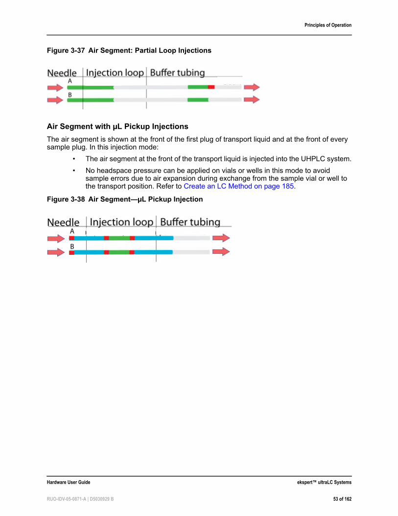
If samples are highly viscous it may be necessary to program larger flush volumes and reduce the syringe speed for better performance. Refer to the color legend for Figure 3-36 on page 52 to Figure 3-38 on page 53.
Table 3-5 Color Legend (Figure 3-36 to Figure 3-38)
Color DescriptionGreen Sample or flush
Grey Eluent
Red Air
Blue Transport
Figure 3-36 Air Segment: Full Loop Injection
ekspert™ ultraLC Systems Hardware User Guide
52 of 162 RUO-IDV-05-0871-A | D5030929 B
Principles of Operation
Air Segment with µL Pickup Injections
The air segment is shown at the front of the first plug of transport liquid and at the front of every sample plug. In this injection mode:
• The air segment at the front of the transport liquid is injected into the UHPLC system.
• No headspace pressure can be applied on vials or wells in this mode to avoid sample errors due to air expansion during exchange from the sample vial or well to the transport position. Refer to Create an LC Method on page 185.
Figure 3-37 Air Segment: Partial Loop Injections
Figure 3-38 Air Segment—µL Pickup Injection
Hardware User Guide ekspert™ ultraLC Systems
RUO-IDV-05-0871-A | D5030929 B 53 of 162
Principles of Operation
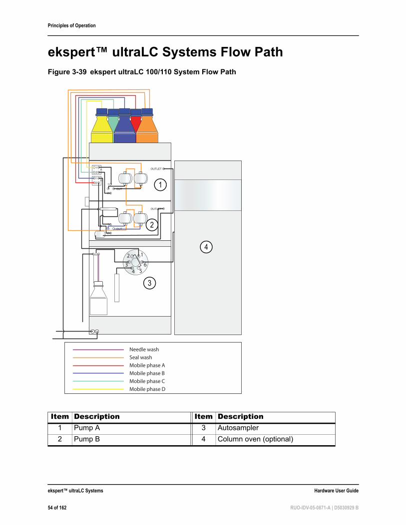
ekspert™ ultraLC Systems Flow PathFigure 3-39 ekspert ultraLC 100/110 System Flow Path
Item Description Item Description1 Pump A 3 Autosampler
2 Pump B 4 Column oven (optional)
OUTLET
OUT
1
2
1
2A
B
1
2
OUTLET
OUT
1
2
1
654
3
2
Seal wash
Mobile phase B
Mobile phase C
Mobile phase A
Needle wash
Mobile phase D
1
2
3
4
ekspert™ ultraLC Systems Hardware User Guide
54 of 162 RUO-IDV-05-0871-A | D5030929 B
Principles of Operation
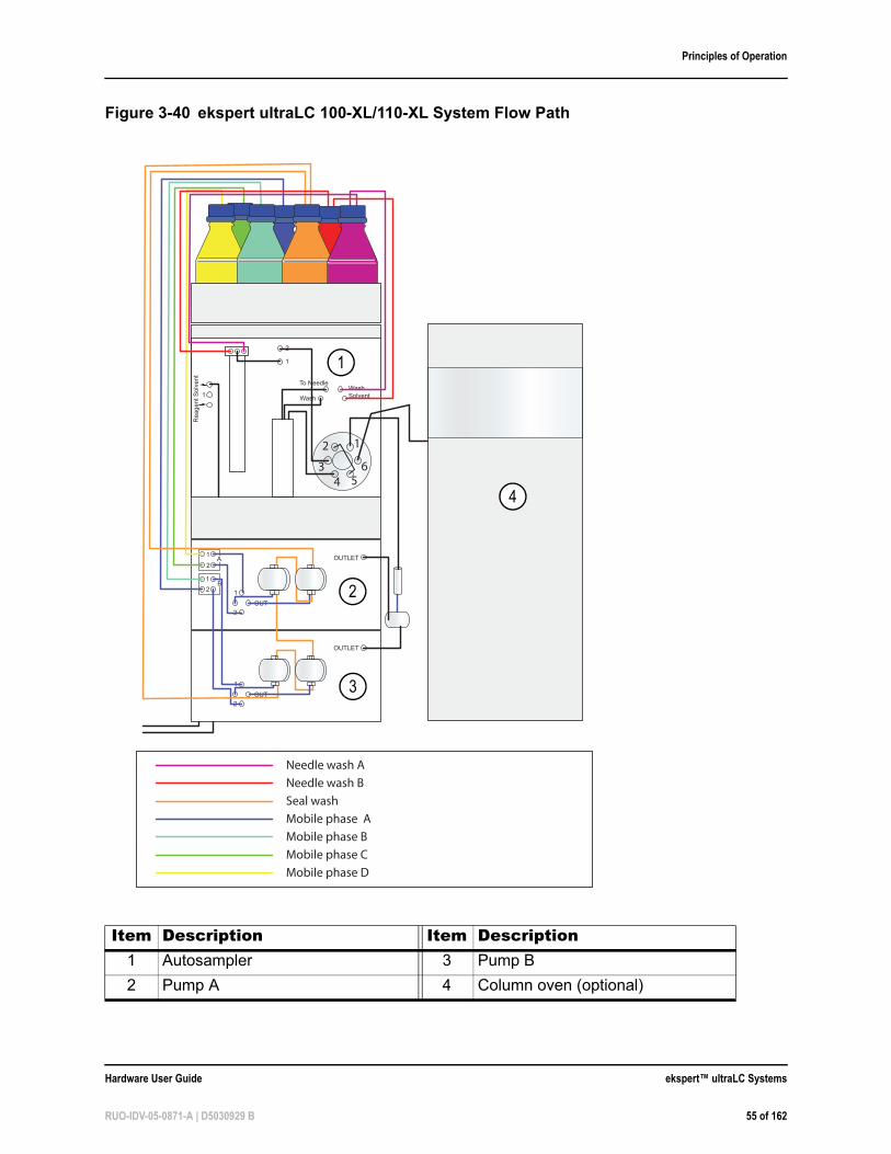
Figure 3-40 ekspert ultraLC 100-XL/110-XL System Flow Path
Item Description Item Description1 Autosampler 3 Pump B
2 Pump A 4 Column oven (optional)
OUTLET
OUT
1
2
1
2A
B
1
2
OUTLET
OUT
1
2
Re
ag
en
t S
olv
en
t
To Needle
Wash
Wash
Solvent
2
1
1
1
654
3
2
Seal wash
Mobile phase A
Mobile phase B
Needle wash B
Needle wash A
Mobile phase C
Mobile phase D
1
2
3
4
Hardware User Guide ekspert™ ultraLC Systems
RUO-IDV-05-0871-A | D5030929 B 55 of 162

Principles of Operation
ekspert™ ultraLC Systems Hardware User Guide
56 of 162 RUO-IDV-05-0871-A | D5030929 B
4
Operating Instructionsekspert™ ultraLC 100/110 PumpThe ekspert™ ultraLC software is required for operation of the pump. Refer to the ekspert™ ultraLC Systems Software User Guide for more information.
Start the Pump
1. Start the Analyst® software.
2. Turn on the pumps.
3. Prepare the solvent bottles and place them in the solvent tray.
4. Make sure that communication between the PC and the pump is properly set up (refer to the ekspert™ ultraLC Systems Software User Guide).
5. Wait until the ekspert ultraLC software indicates that the pump status is Ready.
6. Make sure that the pressure status information in the ekspert ultraLC software is 0 or --.
7. Open the purge valve (one complete turn counterclockwise).
8. Connect the syringe to the drain connector.
9. Press the purge button.
The pump is purged at 2.5 mL/min for 10 minutes.
10. Using the syringe, pull liquid through the pump system until all solvent lines are filled.
11. Wait until the purge action is completed.
12. Close the purge valve (one complete turn clockwise).
13. Increase the pump flow gradually, in steps, to pressurize the system to the value that will be used in the method, monitoring the pressure in the ekspert ultraLC software.
WARNING! Toxic Chemical Hazard: Read the Safety Data sheet prior to handling chemicals. Use assigned personal protective equipment.
Note: Verify that the pump and the ekspert ultraLC software have been properly installed.
Note: Place solvent bottles on a flat, stable surface, in a tray that might serve as a receptacle for leakage.
Note: Make sure that the size of the steps used to pressurize the system is suitable for the size of the column connected to the system. A pressure increase of 3 bar/sec is suitable for most columns.
Hardware User Guide ekspert™ ultraLC Systems
RUO-IDV-05-0871-A | D5030929 B 57 of 162
Operating Instructions
14. Check for leaks at:
• Inlets
• Wash solvent selection valve connections (if any)
• The pump outlet to the column
• Outlets
15. Wait until the pressure is stable.
16. Set the solvent compressibility factor. Refer to the ekspert™ ultraLC Systems Software User Guide.
The pump unit is now ready for use.
Refer to the ekspert ultraLC software Help in the ekspert ultraLC software for more information on programming a run or performing a test gradient.
Purge the PumpsUse the purge button on the pump to prime all solvent lines. Press the purge button to start the action. The standard purge action is programmed at 2.5 mL/min and will continue for 10 minutes. Pressing the purge button again will stop the purge action.
1. Gradually decrease the pump pressure to 0. A step of 3 bar/sec is suitable for most column sizes. Wait until pump pressure is 0 or --.
2. Open the purge valve (one complete turn counterclockwise) to make sure that the column is no longer part of the flow path.
WARNING! Personal Injury Hazard: Always release pressure from the pump slowly by reducing the flow in steps. Never use the purge valve to release pressure. The ultraLC 100/110 pump is an ultra high-pressure system and a significant amount of energy is stored. The energy will be released due to fluid decompression as soon as the purge valve is opened. Never open the purge valve while the system is still pressurized. Because of the pressure difference, mobile phase might squirt out or the pulse dampener might be damaged.
Required Materials• Syringe
ekspert™ ultraLC Systems Hardware User Guide
58 of 162 RUO-IDV-05-0871-A | D5030929 B
Operating Instructions
3. Press the purge button.
4. Use the syringe to draw the solvent through the pump.
5. Wait until the purge action is completed.
6. Close the purge valve (one complete turn, clockwise).
7. Increase the pump flow gradually in steps to pressurize the system to the value that will be used in the method.
Perform a Leak CheckRegularly perform a leak check of the system to verify:
• That the pump pressure is stable: Check the pump pressure in the ekspert ultraLC software.
• Whether there are leaks from the seal wash lines: If the content of the seal wash bottle gradually increases, then there is a leak from the seal wash lines. Check the level of the solvent collected in the seal wash bottle.
Pressure changes or leaks indicate that the plunger surfaces might be scratched or damaged and the plunger must be replaced. Contact an FSE.
Change Seal Wash Solvent
Caution: Potential System Damage: Make sure the Seal wash unit is used at all times. Make sure there is always enough seal wash liquid to prevent damage to pump and plunger seals.
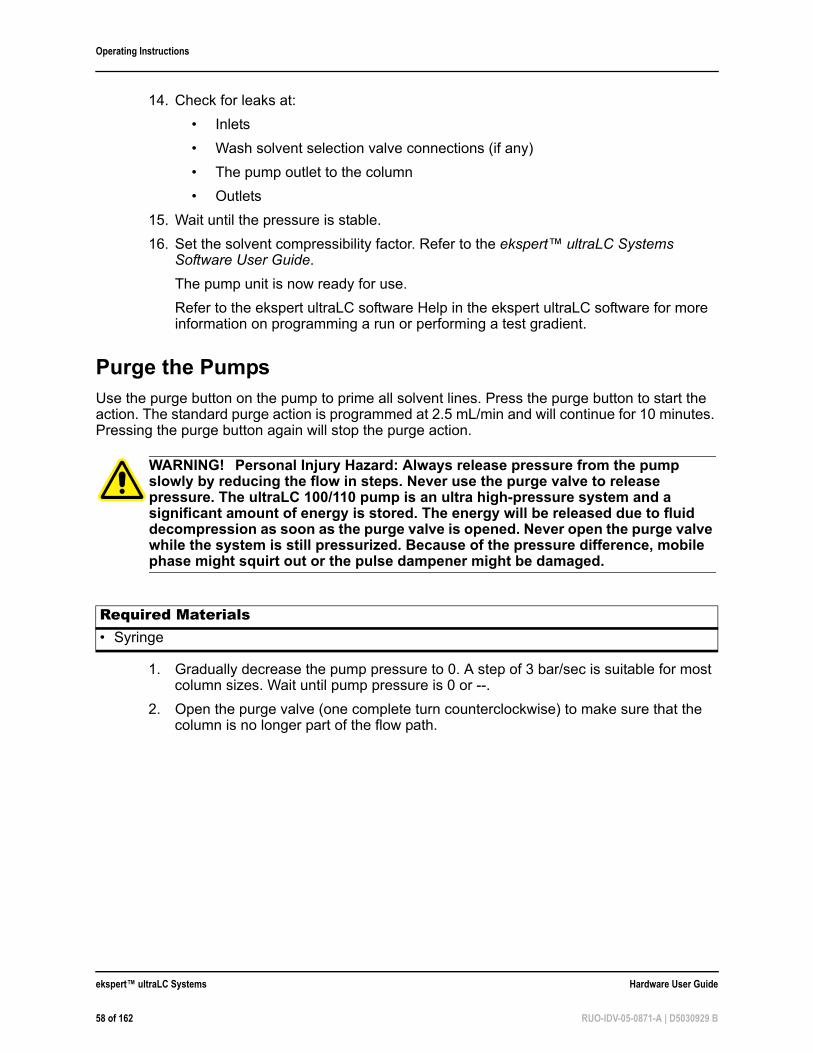
Figure 4-1 The Purge Valve
Item Description1 Purge valve
WARNING! Toxic Chemical Hazard: Read the Safety Data sheet prior to handling chemicals. Use assigned personal protective equipment.
1
Hardware User Guide ekspert™ ultraLC Systems
RUO-IDV-05-0871-A | D5030929 B 59 of 162
Operating Instructions
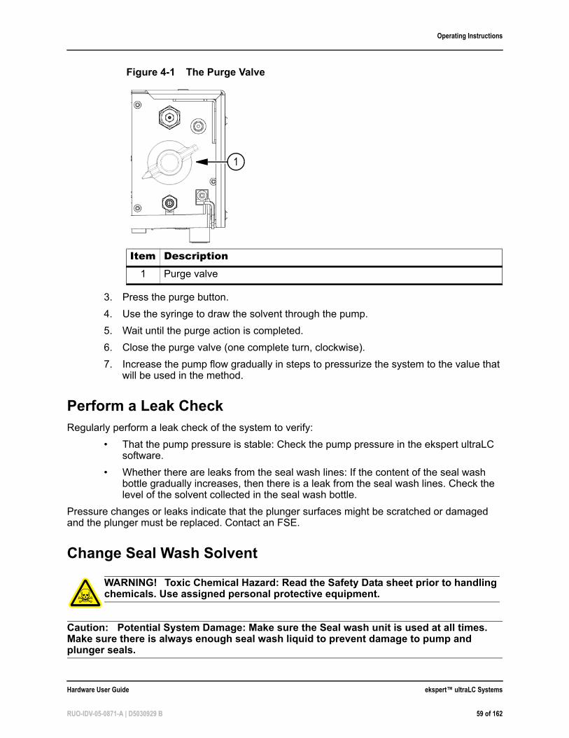
Caution: Potential System Damage: Replace the distilled water/methanol mixture in the seal wash bottle with a fresh mixture every day.
Caution: Potential System Damage: Always replace the tubing if there is contamination inside the seal wash unit tubing.
Caution: Potential System Damage: Use 20:80 methanol:water or 20:80 isopropanol:water.
1. Remove tubing from the seal wash liquid bottle.
2. Use a new bottle, or clean the previous bottle.
a. Remove the cap and then insert a piece of wiping paper in the bottle.b. Clean the inside of the bottle.c. Remove the wiping paper and then ultrasonically clean the bottle with distilled
water for about five minutes.
3. Fill the bottle with a fresh mixture (20:80 methanol:water or isopropanol:water).
4. Replace the cap and tubing and then put the bottle in its location.
Prime the Seal Wash
1. Put the seal wash inlet and outlet tubing into the bottle of IPA.
Figure 4-2 Seal Wash Unit
Required Materials• Syringe with tubing attachment
• Bottle of isopropanol (IPA)
• Bottle of seal wash solution
ekspert™ ultraLC Systems Hardware User Guide
60 of 162 RUO-IDV-05-0871-A | D5030929 B
Operating Instructions
2. Disconnect the seal wash tubing from the top of the right pump head on pump B.
3. Connect a syringe to the seal wash tubing.
4. Pull on the plunger to draw the IPA into the lines.
5. Put the seal wash tubing into the seal wash bottle.
6. Pull on the syringe plunger to draw the seal wash solution into the lines.
7. Connect the seal wash tubing to the top of the right pump head on pump B.
Short-term Shutdown
To shut down the pump for a short term (overnight or for a weekend):
1. Remove harmful mobile phase from the system.
2. Flush the system with 80:20 water:methanol for several minutes, to prevent forming of harmful deposits in the system.
3. Turn off the system.
Refer to Prepare the Pump for Long-Term Storage on page 84 for instructions for long-term shutdown.
Guidelines for Controlling Sample Throughput• For some sample and solvent compositions, perform high speed injections with or
without a fast wash to achieve a cycle time of 20 seconds.
• Monitor injection performance to determine the maximum speed for specific injection conditions.
Guidelines for Using the Sample Temperature Control Option (STC)The sample temperature control option (STC) provides a constant environment for all samples in the sample compartment.
• Choose temperature setpoints between 4ºC and 40ºC.
• To minimize temperature fluctuations minimum, set the required temperature one hour before loading of samples in the sample compartment.
• To maintain a constant temperature, set a temperature close to ambient temperature. This reduces power consumption. Lower setpoints result in higher power consumption and more condensation.
The temperature at the moment of sample injection (actual sample compartment temperature) is displayed by the ekspert ultraLC software and will be included in the wiff data file.
WARNING! Toxic Chemical Hazard: Read the Safety Data sheet prior to handling chemicals. Use assigned personal protective equipment.
Hardware User Guide ekspert™ ultraLC Systems
RUO-IDV-05-0871-A | D5030929 B 61 of 162
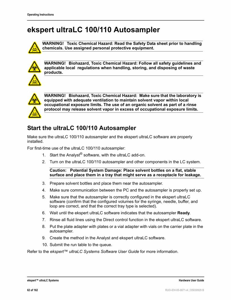
Operating Instructions
ekspert ultraLC 100/110 Autosampler
.
Start the ultraLC 100/110 AutosamplerMake sure the ultraLC 100/110 autosampler and the ekspert ultraLC software are properly installed.
For first-time use of the ultraLC 100/110 autosampler:
1. Start the Analyst® software, with the ultraLC add-on.
2. Turn on the ultraLC 100/110 autosampler and other components in the LC system.
Caution: Potential System Damage: Place solvent bottles on a flat, stable surface and place them in a tray that might serve as a receptacle for leakage.
3. Prepare solvent bottles and place them near the autosampler.
4. Make sure communication between the PC and the autosampler is properly set up.
5. Make sure that the autosampler is correctly configured in the ekspert ultraLC software (confirm that the configured volumes for the syringe, needle, buffer, and loop are correct, and that the correct tray type is selected).
6. Wait until the ekspert ultraLC software indicates that the autosampler Ready.
7. Rinse all fluid lines using the Direct control function in the ekspert ultraLC software.
8. Put the plate adapter with plates or a vial adapter with vials on the carrier plate in the autosampler.
9. Create the method in the Analyst and ekspert ultraLC software.
10. Submit the run table to the queue.
Refer to the ekspert™ ultraLC Systems Software User Guide for more information.
WARNING! Toxic Chemical Hazard: Read the Safety Data sheet prior to handling chemicals. Use assigned personal protective equipment.
WARNING! Biohazard, Toxic Chemical Hazard: Follow all safety guidelines and applicable local regulations when handling, storing, and disposing of waste products.
WARNING! Biohazard, Toxic Chemical Hazard: Make sure that the laboratory is equipped with adequate ventilation to maintain solvent vapor within local occupational exposure limits. The use of an organic solvent as part of a rinse protocol may release solvent vapor in excess of occupational exposure limits.
ekspert™ ultraLC Systems Hardware User Guide
62 of 162 RUO-IDV-05-0871-A | D5030929 B
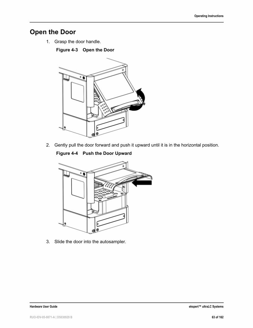
Operating Instructions
Open the Door1. Grasp the door handle.
2. Gently pull the door forward and push it upward until it is in the horizontal position.
3. Slide the door into the autosampler.
Figure 4-3 Open the Door
Figure 4-4 Push the Door Upward
Hardware User Guide ekspert™ ultraLC Systems
RUO-IDV-05-0871-A | D5030929 B 63 of 162
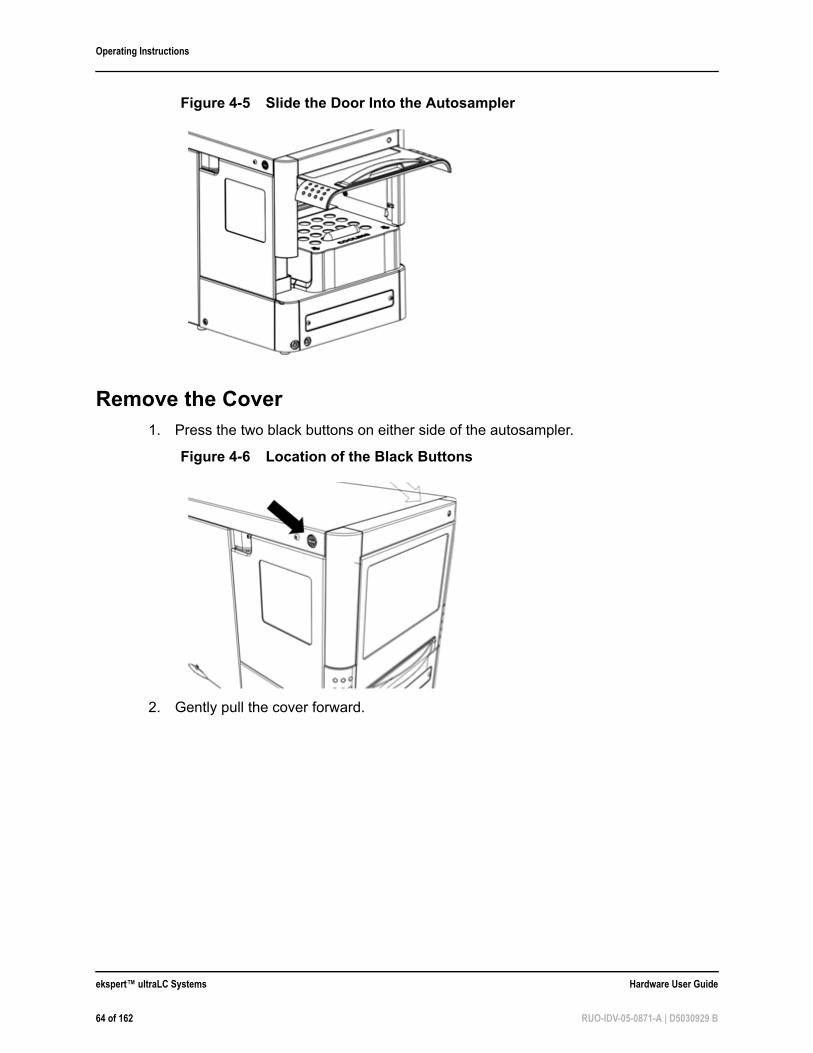
Operating Instructions
Remove the Cover 1. Press the two black buttons on either side of the autosampler.
2. Gently pull the cover forward.
Figure 4-5 Slide the Door Into the Autosampler
Figure 4-6 Location of the Black Buttons
ekspert™ ultraLC Systems Hardware User Guide
64 of 162 RUO-IDV-05-0871-A | D5030929 B
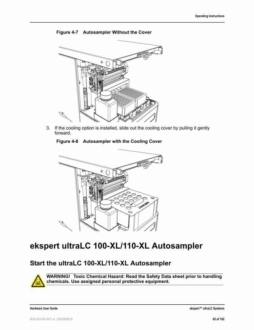
Operating Instructions
3. If the cooling option is installed, slide out the cooling cover by pulling it gently forward.
ekspert ultraLC 100-XL/110-XL Autosampler
Start the ultraLC 100-XL/110-XL Autosampler
Figure 4-7 Autosampler Without the Cover
Figure 4-8 Autosampler with the Cooling Cover
WARNING! Toxic Chemical Hazard: Read the Safety Data sheet prior to handling chemicals. Use assigned personal protective equipment.
Hardware User Guide ekspert™ ultraLC Systems
RUO-IDV-05-0871-A | D5030929 B 65 of 162
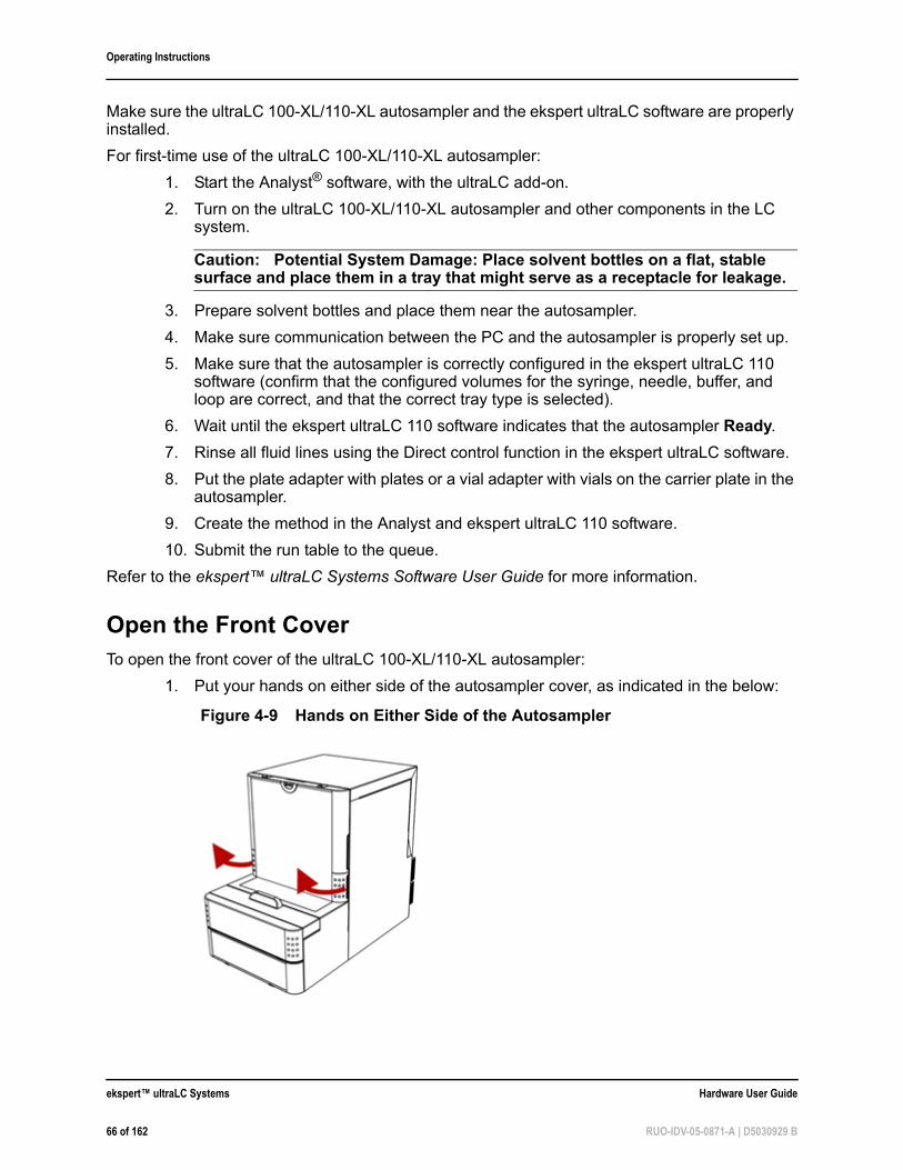
Operating Instructions
Make sure the ultraLC 100-XL/110-XL autosampler and the ekspert ultraLC software are properly installed.
For first-time use of the ultraLC 100-XL/110-XL autosampler:
1. Start the Analyst® software, with the ultraLC add-on.
2. Turn on the ultraLC 100-XL/110-XL autosampler and other components in the LC system.
Caution: Potential System Damage: Place solvent bottles on a flat, stable surface and place them in a tray that might serve as a receptacle for leakage.
3. Prepare solvent bottles and place them near the autosampler.
4. Make sure communication between the PC and the autosampler is properly set up.
5. Make sure that the autosampler is correctly configured in the ekspert ultraLC 110 software (confirm that the configured volumes for the syringe, needle, buffer, and loop are correct, and that the correct tray type is selected).
6. Wait until the ekspert ultraLC 110 software indicates that the autosampler Ready.
7. Rinse all fluid lines using the Direct control function in the ekspert ultraLC software.
8. Put the plate adapter with plates or a vial adapter with vials on the carrier plate in the autosampler.
9. Create the method in the Analyst and ekspert ultraLC 110 software.
10. Submit the run table to the queue.
Refer to the ekspert™ ultraLC Systems Software User Guide for more information.
Open the Front CoverTo open the front cover of the ultraLC 100-XL/110-XL autosampler:
1. Put your hands on either side of the autosampler cover, as indicated in the below:
Figure 4-9 Hands on Either Side of the Autosampler
ekspert™ ultraLC Systems Hardware User Guide
66 of 162 RUO-IDV-05-0871-A | D5030929 B
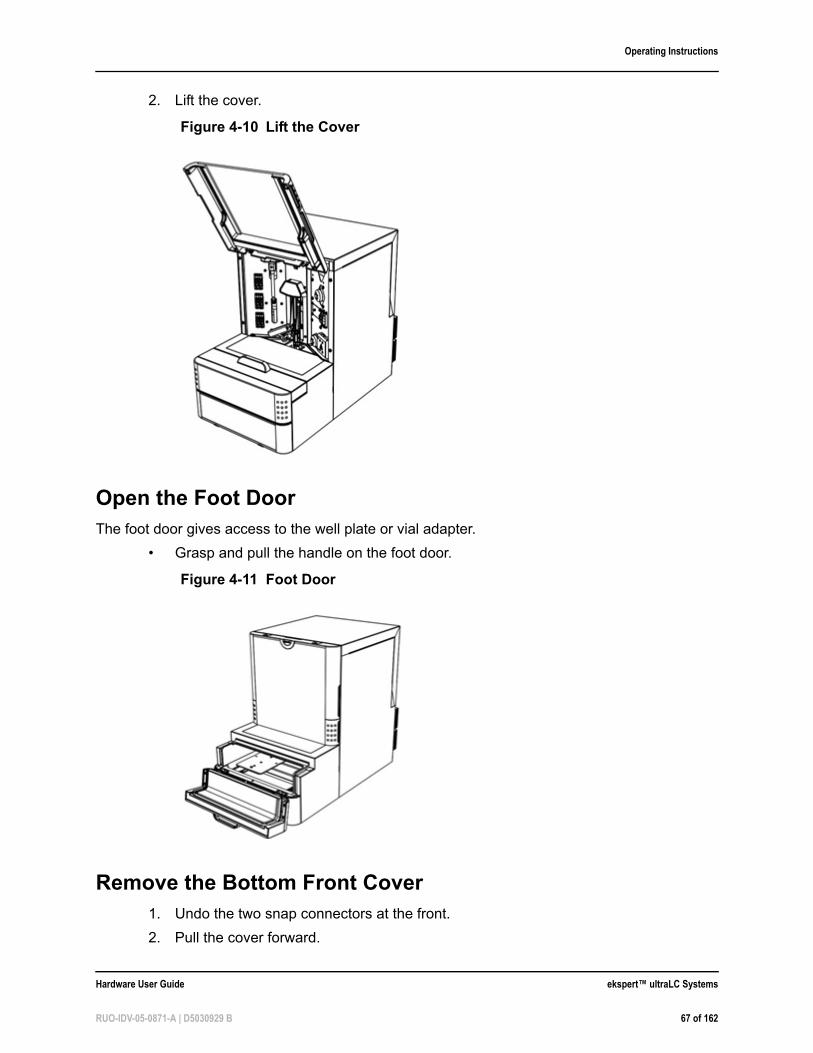
Operating Instructions
2. Lift the cover.
Open the Foot DoorThe foot door gives access to the well plate or vial adapter.
• Grasp and pull the handle on the foot door.
Remove the Bottom Front Cover1. Undo the two snap connectors at the front.
2. Pull the cover forward.
Figure 4-10 Lift the Cover
Figure 4-11 Foot Door
Hardware User Guide ekspert™ ultraLC Systems
RUO-IDV-05-0871-A | D5030929 B 67 of 162
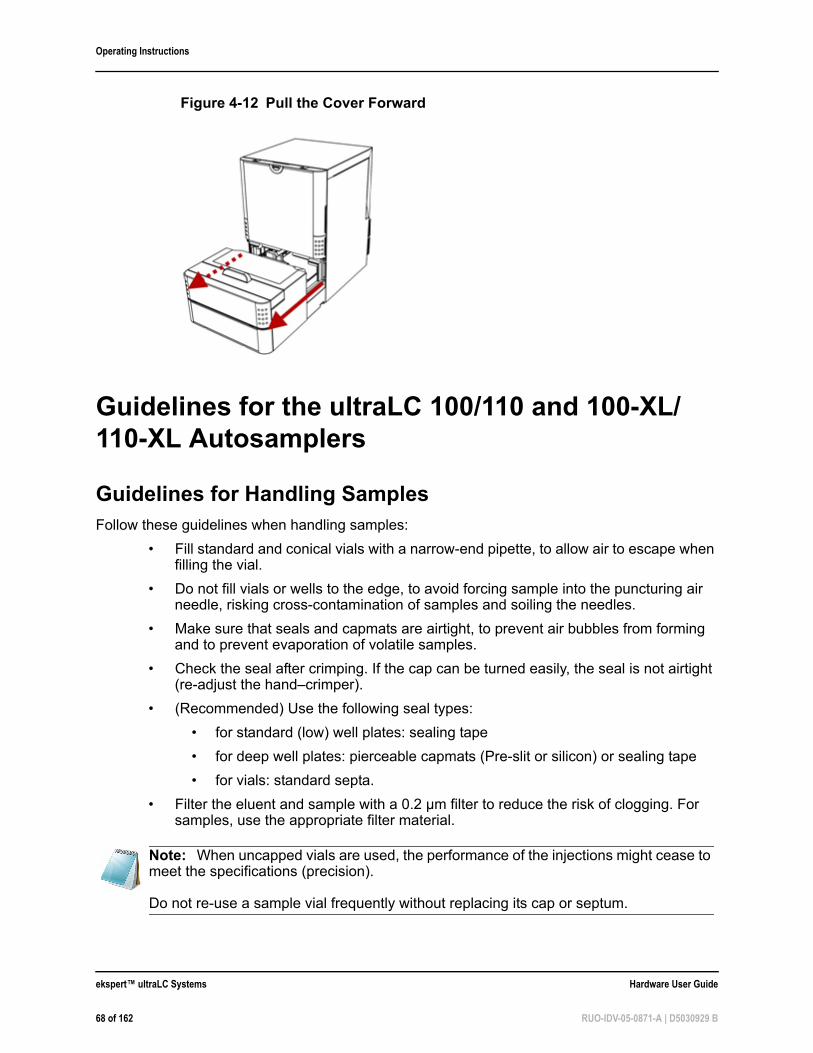
Operating Instructions
Guidelines for the ultraLC 100/110 and 100-XL/110-XL Autosamplers
Guidelines for Handling SamplesFollow these guidelines when handling samples:
• Fill standard and conical vials with a narrow-end pipette, to allow air to escape when filling the vial.
• Do not fill vials or wells to the edge, to avoid forcing sample into the puncturing air needle, risking cross-contamination of samples and soiling the needles.
• Make sure that seals and capmats are airtight, to prevent air bubbles from forming and to prevent evaporation of volatile samples.
• Check the seal after crimping. If the cap can be turned easily, the seal is not airtight (re-adjust the hand–crimper).
• (Recommended) Use the following seal types:
• for standard (low) well plates: sealing tape
• for deep well plates: pierceable capmats (Pre-slit or silicon) or sealing tape
• for vials: standard septa.
• Filter the eluent and sample with a 0.2 µm filter to reduce the risk of clogging. For samples, use the appropriate filter material.
Figure 4-12 Pull the Cover Forward
Note: When uncapped vials are used, the performance of the injections might cease to meet the specifications (precision).
Do not re-use a sample vial frequently without replacing its cap or septum.
ekspert™ ultraLC Systems Hardware User Guide
68 of 162 RUO-IDV-05-0871-A | D5030929 B
Operating Instructions
Guidelines for Working with Sticky Compounds and Matrixes
• For compounds that stick to flow path components, replace components with components made of different materials.
• For compounds that stick to sample vials, replace vials or well plates with vials or well plates of a different material. For example, replace glass vials with plastic ones. Alternatively, use specially coated glass vials or additives.
Samples that stick to sample vials tend to cause lower peak areas after repeated injections from the same vial.
• For compounds that interact with metal parts of the sample, replace parts in the flow path with parts of different materials. For example replace a stainless steel needle with a PEEK, Silica or PEEKsil needle, or replace the standard injection valve with by a PEEK injection valve.
• For compounds that stick to the valve rotor seal, replace the rotor seal with a seal made from a different material.
• To reduce the effects of sticky matrix compounds, use the µL Pickup injection mode. It introduces less of the sample in the fluid lines. In addition, extensive wash capabilities are available to help washing both the inside and the outside of the sample needle with multiple solvents. For example the following wash program steps can be used for cleaning when sticky compounds are analyzed in aqueous non-biological samples:
a. 90% methanolb. 50% methanol + 0.2% formic acidc. 90% methanol
• For biological samples like plasma and blood, use with the following wash sequence to prevent proteins from precipitating in the fluid lines:
a. 40% methanol + 0.2% formic acidb. 40% acetonitrile + 40% methanol + 10% isopropanol + 10% water*c. 10% methanol + 0.2% formic acid
A mixture of acetonitrile, methanol, isopropanol, and water is known to have a good cleaning performance for a variety of compounds.
Working with UHPLCUHPLC injections require a dedicated system configuration with accompanying injection routines. The configuration takes care of minimized tubing volume and allows for operating pressures up to 18 000 psi (1240 bar).
The UHPLC configuration also contains a special injection valve that accommodates for compression and decompression of the sample loop content. This dedicated UHPLC configuration allows for accurate injection volumes and reduces the risks of large pressure transitions and peak distortion.
WARNING! Toxic Chemical Hazard: Read the Safety Data sheet prior to handling chemicals. Use assigned personal protective equipment.
Hardware User Guide ekspert™ ultraLC Systems
RUO-IDV-05-0871-A | D5030929 B 69 of 162
Operating Instructions
Guidelines for Optimizing for Maximum PerformanceMany parameters influence system performance. Some parameters, such as stickiness of compounds, are not related to the autosampler itself.
To increase the repeatability of injections, follow these guidelines:
• Degas wash solvents. Air bubbles in the syringe and buffer tubing might hamper injection performance.
• Remove air bubbles by rinsing the syringe and buffer tubing with isopropanol.
Partial loop injections
• Increase the preflush volume to make sure that the sample does not enter the loop diluted. The preflush volume can be adapted in the ekspert ultraLC software and requires some extra sample for each injection.
• Introduce an air segment before aspirating the sample to prevent major dilution. The preflush volume can then be reduced.
Full loop injections
• Use full loop injections. They provide the best repeatability as the injection volume is determined by the loop size.
• Increase the number of loop flushes, if required.
µL Pickup Injections
• Use µL pickup injections.
Guidelines Working with Sample Containers (Vials and Well Plates)The height of the plates used is automatically detected by the instrument. The puncturing air needle and sample needle heights are programmable in the ekspert ultraLC 110 software:
Various types of caps and capmats can be used. Vials can be closed with crimp and screw caps with needle pierceable septa (silicon, rubber) of various thickness or pre-slit ones. Well plates can also be sealed with either a foil or cap mat without hampering the injection.
• Configure the type of sample container in the ekspert ultraLC 110 software before starting a run. The number of vials or wells cannot be detected automatically.
• Make sure that the sample containers are not overfilled, to prevent the puncturing air needle from coming into contact with the sample.
• Make sure that the puncturing air needle fully punctures the cap, but does not touch the sample.
• Adjust the sample needle height, as required, so that it is only just submerged in the sample surface, or so that that it moves further down to the bottom of the sample container.
ekspert™ ultraLC Systems Hardware User Guide
70 of 162 RUO-IDV-05-0871-A | D5030929 B
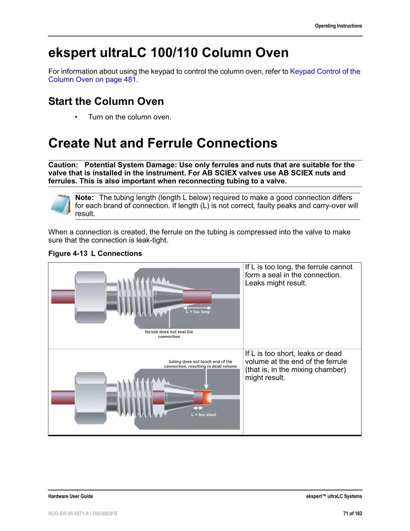
Operating Instructions
ekspert ultraLC 100/110 Column OvenFor information about using the keypad to control the column oven, refer to Keypad Control of the Column Oven on page 481.
Start the Column Oven• Turn on the column oven.
Create Nut and Ferrule Connections
Caution: Potential System Damage: Use only ferrules and nuts that are suitable for the valve that is installed in the instrument. For AB SCIEX valves use AB SCIEX nuts and ferrules. This is also important when reconnecting tubing to a valve.
When a connection is created, the ferrule on the tubing is compressed into the valve to make sure that the connection is leak-tight.
Note: The tubing length (length L below) required to make a good connection differs for each brand of connection. If length (L) is not correct, faulty peaks and carry-over will result.
Figure 4-13 L Connections
If L is too long, the ferrule cannot form a seal in the connection. Leaks might result.
If L is too short, leaks or dead volume at the end of the ferrule (that is, in the mixing chamber) might result.
Hardware User Guide ekspert™ ultraLC Systems
RUO-IDV-05-0871-A | D5030929 B 71 of 162
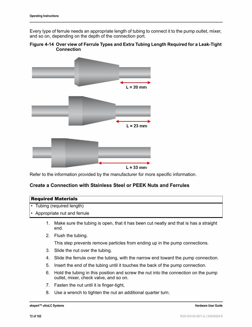
Operating Instructions
Every type of ferrule needs an appropriate length of tubing to connect it to the pump outlet, mixer, and so on, depending on the depth of the connection port.
Refer to the information provided by the manufacturer for more specific information.
Create a Connection with Stainless Steel or PEEK Nuts and Ferrules
1. Make sure the tubing is open, that it has been cut neatly and that is has a straight end.
2. Flush the tubing.
This step prevents remove particles from ending up in the pump connections.
3. Slide the nut over the tubing.
4. Slide the ferrule over the tubing, with the narrow end toward the pump connection.
5. Insert the end of the tubing until it touches the back of the pump connection.
6. Hold the tubing in this position and screw the nut into the connection on the pump outlet, mixer, check valve, and so on.
7. Fasten the nut until it is finger-tight,
8. Use a wrench to tighten the nut an additional quarter turn.
Figure 4-14 Over view of Ferrule Types and Extra Tubing Length Required for a Leak-Tight Connection
Required Materials• Tubing (required length)
• Appropriate nut and ferrule
ekspert™ ultraLC Systems Hardware User Guide
72 of 162 RUO-IDV-05-0871-A | D5030929 B
Operating Instructions
The connection is now leak-tight.
Hardware User Guide ekspert™ ultraLC Systems
RUO-IDV-05-0871-A | D5030929 B 73 of 162

Operating Instructions
ekspert™ ultraLC Systems Hardware User Guide
74 of 162 RUO-IDV-05-0871-A | D5030929 B
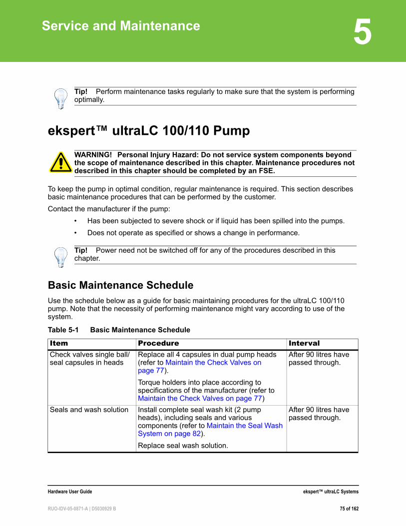
5
Service and Maintenanceekspert™ ultraLC 100/110 Pump
To keep the pump in optimal condition, regular maintenance is required. This section describes basic maintenance procedures that can be performed by the customer.
Contact the manufacturer if the pump:
• Has been subjected to severe shock or if liquid has been spilled into the pumps.
• Does not operate as specified or shows a change in performance.
Basic Maintenance ScheduleUse the schedule below as a guide for basic maintaining procedures for the ultraLC 100/110 pump. Note that the necessity of performing maintenance might vary according to use of the system.
Tip! Perform maintenance tasks regularly to make sure that the system is performing optimally.
WARNING! Personal Injury Hazard: Do not service system components beyond the scope of maintenance described in this chapter. Maintenance procedures not described in this chapter should be completed by an FSE.
Tip! Power need not be switched off for any of the procedures described in this chapter.
Table 5-1 Basic Maintenance Schedule
Item Procedure IntervalCheck valves single ball/seal capsules in heads
Replace all 4 capsules in dual pump heads (refer to Maintain the Check Valves on page 77).
Torque holders into place according to specifications of the manufacturer (refer to Maintain the Check Valves on page 77)
After 90 litres have passed through.
Seals and wash solution Install complete seal wash kit (2 pump heads), including seals and various components (refer to Maintain the Seal Wash System on page 82).
Replace seal wash solution.
After 90 litres have passed through.
Hardware User Guide ekspert™ ultraLC Systems
RUO-IDV-05-0871-A | D5030929 B 75 of 162
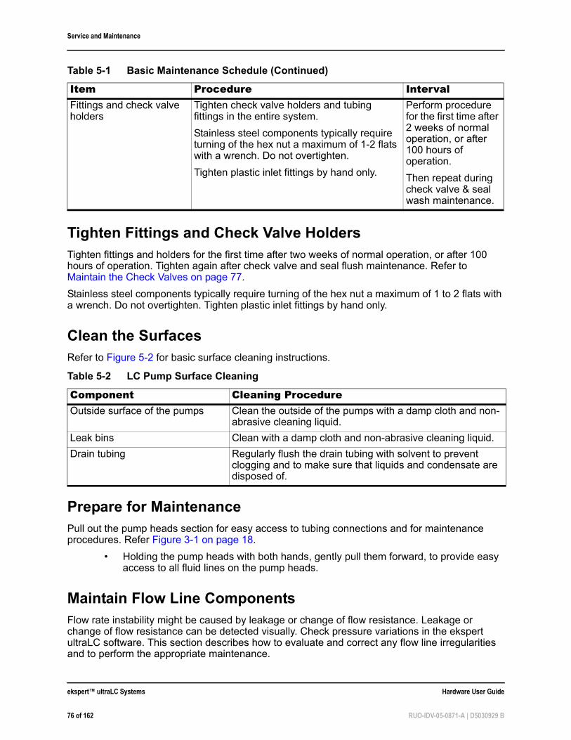
Service and Maintenance
Tighten Fittings and Check Valve HoldersTighten fittings and holders for the first time after two weeks of normal operation, or after 100 hours of operation. Tighten again after check valve and seal flush maintenance. Refer to Maintain the Check Valves on page 77.
Stainless steel components typically require turning of the hex nut a maximum of 1 to 2 flats with a wrench. Do not overtighten. Tighten plastic inlet fittings by hand only.
Clean the SurfacesRefer to Figure 5-2 for basic surface cleaning instructions.
Prepare for MaintenancePull out the pump heads section for easy access to tubing connections and for maintenance procedures. Refer Figure 3-1 on page 18.
• Holding the pump heads with both hands, gently pull them forward, to provide easy access to all fluid lines on the pump heads.
Maintain Flow Line ComponentsFlow rate instability might be caused by leakage or change of flow resistance. Leakage or change of flow resistance can be detected visually. Check pressure variations in the ekspert ultraLC software. This section describes how to evaluate and correct any flow line irregularities and to perform the appropriate maintenance.
Fittings and check valve holders
Tighten check valve holders and tubing fittings in the entire system.
Stainless steel components typically require turning of the hex nut a maximum of 1-2 flats with a wrench. Do not overtighten.
Tighten plastic inlet fittings by hand only.
Perform procedure for the first time after 2 weeks of normal operation, or after 100 hours of operation.
Then repeat during check valve & seal wash maintenance.
Table 5-2 LC Pump Surface Cleaning
Component Cleaning ProcedureOutside surface of the pumps Clean the outside of the pumps with a damp cloth and non-
abrasive cleaning liquid.
Leak bins Clean with a damp cloth and non-abrasive cleaning liquid.
Drain tubing Regularly flush the drain tubing with solvent to prevent clogging and to make sure that liquids and condensate are disposed of.
Table 5-1 Basic Maintenance Schedule (Continued)
Item Procedure Interval
ekspert™ ultraLC Systems Hardware User Guide
76 of 162 RUO-IDV-05-0871-A | D5030929 B
Service and Maintenance
1. Make sure that all degasser tubing is properly connected to prevent leakage.
Leakage at tubing means that the degasser cannot build up a vacuum and no degassing will take place.
2. Make sure that all mixer tubing is properly connected to prevent leakage.
If the mixer tubing is blocked, pressure may build up in the mixing chamber.
3. Confirm that the solvent filter is not clogged.
The solvent filter may become clogged after a long period of use or when contaminated solvents are used. If the solvent filter is clogged, pressure is reduced inside the solvent filter during use. As a result, dissolved air will form air bubbles, which can cause a fluctuation of the flow rate.
a. Remove the solvent filter.b. Monitor the pressure. If the pressure increases after removing the filter, the
solvent filter is clogged.c. If the filter is clogged, use ultrasonic cleaning or replace it with a new one.
Refer to Clean and Inspect the Solvent Filter on page 77.Because the solvent filter protects the degasser, plunger seal, pump check valves, and column from foreign matter in the solvent, make sure that the solvent filter is installed correctly during normal operation.
Clean and Inspect the Solvent Filter
The solvent filter might become clogged after a long period of use or when contaminated solvents are used. If the solvent filter is clogged, pressure is reduced inside the solvent filter during use. As a result, dissolved air will form air bubbles, which can cause fluctuation of the flow rate. To check:
1. Remove the solvent filter from the tubing.
2. Put the solvent filter in a bath of isopropanol and then sonicate for five minutes.
3. Plug in the pump and turn it on.
4. In the ekspert ultraLC software, set the flow rate set point to 1 mL/min and start the flow.
5. Check for air bubbles accumulating inside the tubing. (Bubbles indicate that the filter must be replaced.)
6. Replace the solvent filter if cleaning has not solved the original issue.
Maintain the Check Valves
Poor reproducibility of retention time and unstable delivery pressure might be caused by a soiled check valve.
• Purge the system with isopropanol. Refer to Purge the Pumps on page 58).
If the issue still exists, contact an FSE to replace the check valves.
Hardware User Guide ekspert™ ultraLC Systems
RUO-IDV-05-0871-A | D5030929 B 77 of 162
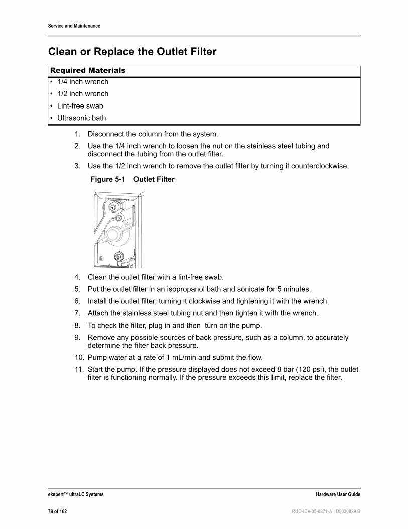
Service and Maintenance
Clean or Replace the Outlet Filter
1. Disconnect the column from the system.
2. Use the 1/4 inch wrench to loosen the nut on the stainless steel tubing and disconnect the tubing from the outlet filter.
3. Use the 1/2 inch wrench to remove the outlet filter by turning it counterclockwise.
4. Clean the outlet filter with a lint-free swab.
5. Put the outlet filter in an isopropanol bath and sonicate for 5 minutes.
6. Install the outlet filter, turning it clockwise and tightening it with the wrench.
7. Attach the stainless steel tubing nut and then tighten it with the wrench.
8. To check the filter, plug in and then turn on the pump.
9. Remove any possible sources of back pressure, such as a column, to accurately determine the filter back pressure.
10. Pump water at a rate of 1 mL/min and submit the flow.
11. Start the pump. If the pressure displayed does not exceed 8 bar (120 psi), the outlet filter is functioning normally. If the pressure exceeds this limit, replace the filter.
Required Materials• 1/4 inch wrench
• 1/2 inch wrench
• Lint-free swab
• Ultrasonic bath
Figure 5-1 Outlet Filter
ekspert™ ultraLC Systems Hardware User Guide
78 of 162 RUO-IDV-05-0871-A | D5030929 B
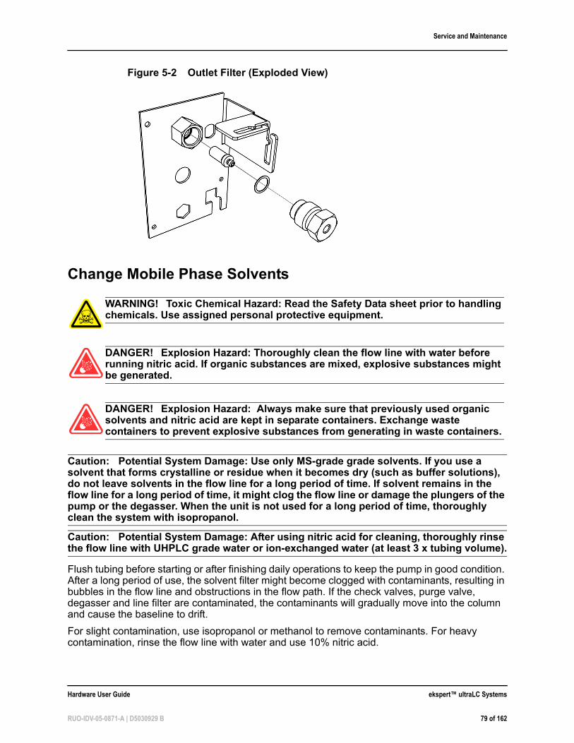
Service and Maintenance
Change Mobile Phase Solvents
Caution: Potential System Damage: Use only MS-grade grade solvents. If you use a solvent that forms crystalline or residue when it becomes dry (such as buffer solutions), do not leave solvents in the flow line for a long period of time. If solvent remains in the flow line for a long period of time, it might clog the flow line or damage the plungers of the pump or the degasser. When the unit is not used for a long period of time, thoroughly clean the system with isopropanol.
Caution: Potential System Damage: After using nitric acid for cleaning, thoroughly rinse the flow line with UHPLC grade water or ion-exchanged water (at least 3 x tubing volume).
Flush tubing before starting or after finishing daily operations to keep the pump in good condition. After a long period of use, the solvent filter might become clogged with contaminants, resulting in bubbles in the flow line and obstructions in the flow path. If the check valves, purge valve, degasser and line filter are contaminated, the contaminants will gradually move into the column and cause the baseline to drift.
For slight contamination, use isopropanol or methanol to remove contaminants. For heavy contamination, rinse the flow line with water and use 10% nitric acid.
Figure 5-2 Outlet Filter (Exploded View)
WARNING! Toxic Chemical Hazard: Read the Safety Data sheet prior to handling chemicals. Use assigned personal protective equipment.
DANGER! Explosion Hazard: Thoroughly clean the flow line with water before running nitric acid. If organic substances are mixed, explosive substances might be generated.
DANGER! Explosion Hazard: Always make sure that previously used organic solvents and nitric acid are kept in separate containers. Exchange waste containers to prevent explosive substances from generating in waste containers.
Hardware User Guide ekspert™ ultraLC Systems
RUO-IDV-05-0871-A | D5030929 B 79 of 162
Service and Maintenance
When changing from a buffer solution to an organic solvent, change the solvent in the following order to prevent precipitation of salt in the buffer solution:
1. Buffer solution
2. Distilled water (or ion-exchanged water)
3. Isopropanol
4. Organic solvent
Switch Mobile Phase Solvents
1. Gradually decrease the pump pressure to 0. A step of 3 bar/sec is suitable for most column sizes. Wait until pump pressure is 0 or --.
2. Select the pump inlet port to which the solvent will be connected.
3. Connect the solvent bottle tubing to the pump inlet port.
4. Purge the pumps. Refer to Purge the Pumps on page 58.
5. Set the flow rate for the pump to the value that will be used at the start of the gradient in the application.
6. Continue pumping for at least 10 column volumes to equilibrate the column.
Switch to a New Bottle of Solvent that is Miscible with Previously Used Solvent
1. Gradually decrease the pump pressure to 0. A step of 3 bar/sec is suitable for most column sizes. Wait until pump pressure is 0 or --.
2. Open the purge valve by turning the knob counter-clockwise one complete turn.
3. Set the flow rate for the pump to 5 mL/min, and purge for 2 minutes.
4. Put the solvent to be used next in a clean bottle.
5. Remove the solvent filter of the delivery pump from the bottle containing the previously used solvent.
6. Clean the solvent filter. Refer to Clean and Inspect the Solvent Filter on page 77.
7. Put the solvent filter in the new solvent bottle. Verify that the solvent is still connected to the same solvent port.
8. Press the purge button on pump A to fill the solvent lines.
The pump will be purged at 2.5mL/min for 10 minutes.
9. Wait until the purge action is completed.
10. Press the purge button on pump B to fill the solvent lines.
11. Wait until the purge action is completed.
Tip! Put the mobile phase reservoir at the same level or higher than the pump. Mobile phases should be degassed, filtered and covered.
WARNING! Personal Injury Hazard: Check the compatibility of solvents before connecting any solvents.
ekspert™ ultraLC Systems Hardware User Guide
80 of 162 RUO-IDV-05-0871-A | D5030929 B
Service and Maintenance
12. Adjust the flow rate to the value that will be used in the method and make sure the degasser is on.
13. Close the purge valve.
14. Start the pump and continue pumping to make sure that the solvent lines are filled and degassed.
Usually, it is sufficient to pump a volume of 10 x column volume.
Switch to a Solvent that is not Miscible with Previously Used Solvent
1. Use a transitional cleaning solvent that is miscible with both the preceding and subsequent solvents (such as isopropanol).
2. Replace the preceding solvent with the transitional cleaning solvent.
3. Replace the transitional cleaning solvent with the new solvent.
4. Each time a solvent is substituted, refer to Switch to a New Bottle of Solvent that is Miscible with Previously Used Solvent on page 80.
Change the Buffer Solution
This procedure prevents precipitation of salt contained in the buffer solution. Be careful not to run an organic solvent before cleaning the flow line with distilled water or ion-exchanged water because crystals or residue might form.
1. When using a buffer solution as either the preceding or subsequent solvent, use distilled water as the transitional solvent.
2. Replace the preceding solvent with distilled water.
3. Replace the distilled water with the new solvent.
Maintain the Degasser
Caution: Potential System Damage: Do not connect the vacuum degasser to the output side of the pump. The high pressure can cause permanent damage to the degasser. Never prime the degasser by pushing solvent through it (for example, by connecting a syringe to the inlet and pushing solvent through the vacuum chamber), as this causes the connections inside the chamber to leak. Always pull the solvent through the chamber using a syringe at the outlet.
On a routine basis:
• Plug any unused ports of the degasser.
• Verify the condition of the solvent filters and replace them, if necessary. If the solvent filters are clogged, the particulate prevents solvent from entering the degasser. Refer to Clean and Inspect the Solvent Filter on page 77.
• Verify all tubing connections to the solvent bottles and the degasser, as well as the pump tubing connections from the degasser. Replace the tubing if there is discoloration or cracks.
Hardware User Guide ekspert™ ultraLC Systems
RUO-IDV-05-0871-A | D5030929 B 81 of 162
Service and Maintenance
• Perform a leak check around the solvent connectors. If a leak occurs at a connector, then tighten the fitting with an additional 1/8 turn. If the leak persists, disconnect the leaking fitting and inspect it. If the nut and ferrule appear to be in good condition, reconnect the fitting. If the leak persists, replace the nut and ferrule and create a leak-free connection.
Replace the MixerPump B is equipped with a 60 µL mixer.
1. Make sure that the pump unit is not pressurized (that is, flow = 0).
2. Remove connections to the mixer.
3. Remove the mixer from its clamp on the front of the pump and then replace it with a new one.
4. Connect the mixer from the outlet (autosampler valve) to Pump A and to Pump B.
Maintain the Seal Wash System
WARNING! Toxic Chemical Hazard: Read the Safety Data sheet prior to handling chemicals. Use assigned personal protective equipment.
ekspert™ ultraLC Systems Hardware User Guide
82 of 162 RUO-IDV-05-0871-A | D5030929 B
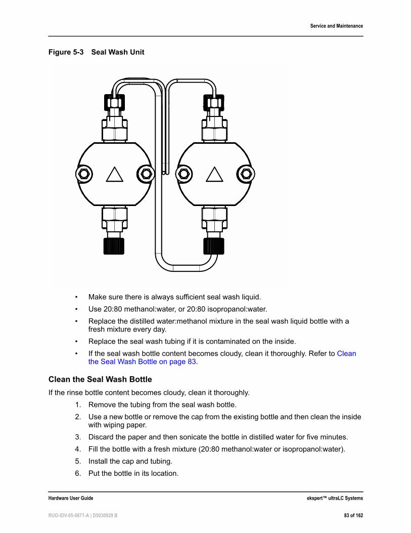
Service and Maintenance
• Make sure there is always sufficient seal wash liquid.
• Use 20:80 methanol:water, or 20:80 isopropanol:water.
• Replace the distilled water:methanol mixture in the seal wash liquid bottle with a fresh mixture every day.
• Replace the seal wash tubing if it is contaminated on the inside.
• If the seal wash bottle content becomes cloudy, clean it thoroughly. Refer to Clean the Seal Wash Bottle on page 83.
Clean the Seal Wash Bottle
If the rinse bottle content becomes cloudy, clean it thoroughly.
1. Remove the tubing from the seal wash bottle.
2. Use a new bottle or remove the cap from the existing bottle and then clean the inside with wiping paper.
3. Discard the paper and then sonicate the bottle in distilled water for five minutes.
4. Fill the bottle with a fresh mixture (20:80 methanol:water or isopropanol:water).
5. Install the cap and tubing.
6. Put the bottle in its location.
Figure 5-3 Seal Wash Unit
Hardware User Guide ekspert™ ultraLC Systems
RUO-IDV-05-0871-A | D5030929 B 83 of 162
Service and Maintenance
Prepare the Pump for Long-Term Storage
1. Remove harmful mobile phase from the system by flushing all ports with 20:80 methanol:water.
2. Gradually decrease the pressure in the system to 0 or --.
3. Disconnect tubing from the degasser ports, and then put a plug (supplied with the pump) in each degasser port.
4. If applicable, disconnect the tubing from the degasser to the solvent selection valve, and then put a plug in each port on the solvent selection valve.
5. Disconnect the tubing from the inlets on the pump heads and then insert a plug in each inlet.
6. Disconnect the tubing from the pump outlet to the mixer and then put a stopper in the outlet.
7. Disconnect the tubing from the mixer and then put plugs in the mixer ports.
8. Close the purge valve.
9. Remove the tubing from the seal wash ports. No plugs are required.
10. Turn off the pump.
Prepare the Pump for Transport
Caution: Potential System Damage: Use the original transport screw to lock the pump head. Refer to Figure 5-4.
WARNING! Toxic Chemical Hazard: Read the Safety Data sheet prior to handling chemicals. Use assigned personal protective equipment.
Note: It is not necessary to disconnect tubing from the outlets on the pump heads.
Prerequisite Procedures• Prepare the Pump for Long-Term Storage on page 84
ekspert™ ultraLC Systems Hardware User Guide
84 of 162 RUO-IDV-05-0871-A | D5030929 B
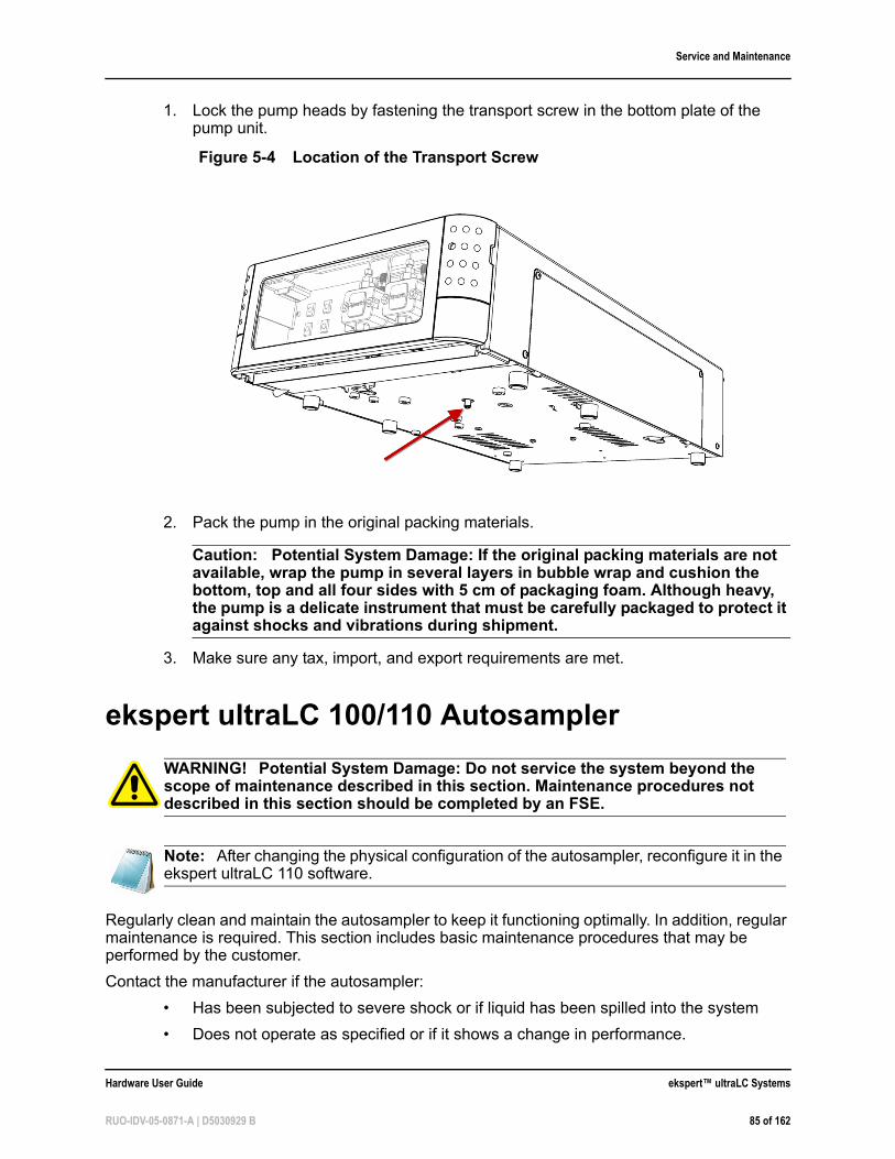
Service and Maintenance
1. Lock the pump heads by fastening the transport screw in the bottom plate of the pump unit.
2. Pack the pump in the original packing materials.
Caution: Potential System Damage: If the original packing materials are not available, wrap the pump in several layers in bubble wrap and cushion the bottom, top and all four sides with 5 cm of packaging foam. Although heavy, the pump is a delicate instrument that must be carefully packaged to protect it against shocks and vibrations during shipment.
3. Make sure any tax, import, and export requirements are met.
ekspert ultraLC 100/110 Autosampler
Regularly clean and maintain the autosampler to keep it functioning optimally. In addition, regular maintenance is required. This section includes basic maintenance procedures that may be performed by the customer.
Contact the manufacturer if the autosampler:
• Has been subjected to severe shock or if liquid has been spilled into the system
• Does not operate as specified or if it shows a change in performance.
Figure 5-4 Location of the Transport Screw
WARNING! Potential System Damage: Do not service the system beyond the scope of maintenance described in this section. Maintenance procedures not described in this section should be completed by an FSE.
Note: After changing the physical configuration of the autosampler, reconfigure it in the ekspert ultraLC 110 software.
Hardware User Guide ekspert™ ultraLC Systems
RUO-IDV-05-0871-A | D5030929 B 85 of 162
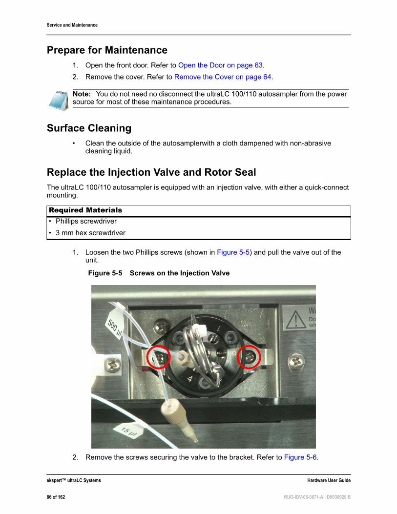
Service and Maintenance
Prepare for Maintenance1. Open the front door. Refer to Open the Door on page 63.
2. Remove the cover. Refer to Remove the Cover on page 64.
Surface Cleaning• Clean the outside of the autosamplerwith a cloth dampened with non-abrasive
cleaning liquid.
Replace the Injection Valve and Rotor SealThe ultraLC 100/110 autosampler is equipped with an injection valve, with either a quick-connect mounting.
1. Loosen the two Phillips screws (shown in Figure 5-5) and pull the valve out of the unit.
2. Remove the screws securing the valve to the bracket. Refer to Figure 5-6.
Note: You do not need no disconnect the ultraLC 100/110 autosampler from the power source for most of these maintenance procedures.
Required Materials• Phillips screwdriver
• 3 mm hex screwdriver
Figure 5-5 Screws on the Injection Valve
ekspert™ ultraLC Systems Hardware User Guide
86 of 162 RUO-IDV-05-0871-A | D5030929 B
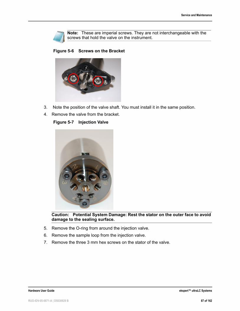
Service and Maintenance
3. Note the position of the valve shaft. You must install it in the same position.
4. Remove the valve from the bracket.
Caution: Potential System Damage: Rest the stator on the outer face to avoid damage to the sealing surface.
5. Remove the O-ring from around the injection valve.
6. Remove the sample loop from the injection valve.
7. Remove the three 3 mm hex screws on the stator of the valve.
Note: These are imperial screws. They are not interchangeable with the screws that hold the valve on the instrument.
Figure 5-6 Screws on the Bracket
Figure 5-7 Injection Valve
Hardware User Guide ekspert™ ultraLC Systems
RUO-IDV-05-0871-A | D5030929 B 87 of 162
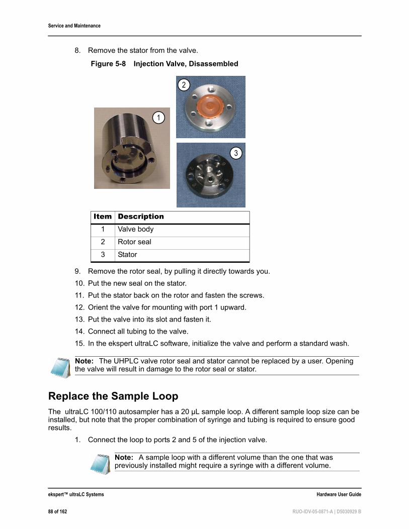
Service and Maintenance
8. Remove the stator from the valve.
9. Remove the rotor seal, by pulling it directly towards you.
10. Put the new seal on the stator.
11. Put the stator back on the rotor and fasten the screws.
12. Orient the valve for mounting with port 1 upward.
13. Put the valve into its slot and fasten it.
14. Connect all tubing to the valve.
15. In the ekspert ultraLC software, initialize the valve and perform a standard wash.
Replace the Sample LoopThe ultraLC 100/110 autosampler has a 20 µL sample loop. A different sample loop size can be installed, but note that the proper combination of syringe and tubing is required to ensure good results.
1. Connect the loop to ports 2 and 5 of the injection valve.
Figure 5-8 Injection Valve, Disassembled
Item Description1 Valve body
2 Rotor seal
3 Stator
Note: The UHPLC valve rotor seal and stator cannot be replaced by a user. Opening the valve will result in damage to the rotor seal or stator.
Note: A sample loop with a different volume than the one that was previously installed might require a syringe with a different volume.
2
1
3
ekspert™ ultraLC Systems Hardware User Guide
88 of 162 RUO-IDV-05-0871-A | D5030929 B
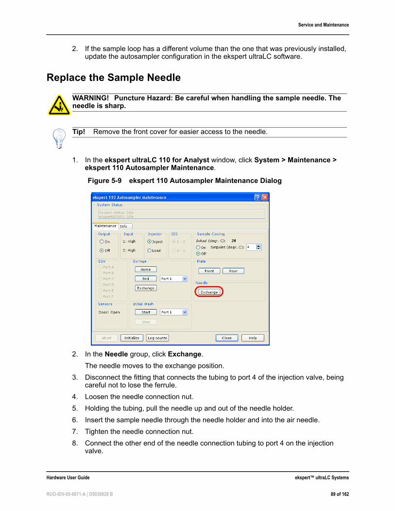
Service and Maintenance
2. If the sample loop has a different volume than the one that was previously installed, update the autosampler configuration in the ekspert ultraLC software.
Replace the Sample Needle
1. In the ekspert ultraLC 110 for Analyst window, click System > Maintenance > ekspert 110 Autosampler Maintenance.
2. In the Needle group, click Exchange.
The needle moves to the exchange position.
3. Disconnect the fitting that connects the tubing to port 4 of the injection valve, being careful not to lose the ferrule.
4. Loosen the needle connection nut.
5. Holding the tubing, pull the needle up and out of the needle holder.
6. Insert the sample needle through the needle holder and into the air needle.
7. Tighten the needle connection nut.
8. Connect the other end of the needle connection tubing to port 4 on the injection valve.
WARNING! Puncture Hazard: Be careful when handling the sample needle. The needle is sharp.
Tip! Remove the front cover for easier access to the needle.
Figure 5-9 ekspert 110 Autosampler Maintenance Dialog
Hardware User Guide ekspert™ ultraLC Systems
RUO-IDV-05-0871-A | D5030929 B 89 of 162
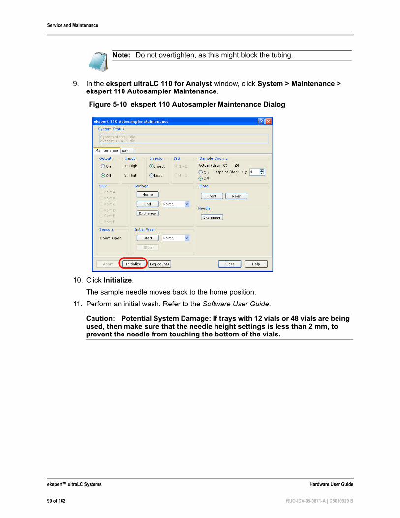
Service and Maintenance
9. In the ekspert ultraLC 110 for Analyst window, click System > Maintenance > ekspert 110 Autosampler Maintenance.
10. Click Initialize.
The sample needle moves back to the home position.
11. Perform an initial wash. Refer to the Software User Guide.
Caution: Potential System Damage: If trays with 12 vials or 48 vials are being used, then make sure that the needle height settings is less than 2 mm, to prevent the needle from touching the bottom of the vials.
Note: Do not overtighten, as this might block the tubing.
Figure 5-10 ekspert 110 Autosampler Maintenance Dialog
ekspert™ ultraLC Systems Hardware User Guide
90 of 162 RUO-IDV-05-0871-A | D5030929 B
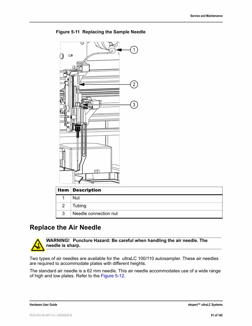
Service and Maintenance
Replace the Air Needle
Two types of air needles are available for the ultraLC 100/110 autosampler. These air needles are required to accommodate plates with different heights.
The standard air needle is a 62 mm needle. This air needle accommodates use of a wide range of high and low plates. Refer to the Figure 5-12.
Figure 5-11 Replacing the Sample Needle
Item Description1 Nut
2 Tubing
3 Needle connection nut
WARNING! Puncture Hazard: Be careful when handling the air needle. The needle is sharp.
1
2
3
Hardware User Guide ekspert™ ultraLC Systems
RUO-IDV-05-0871-A | D5030929 B 91 of 162
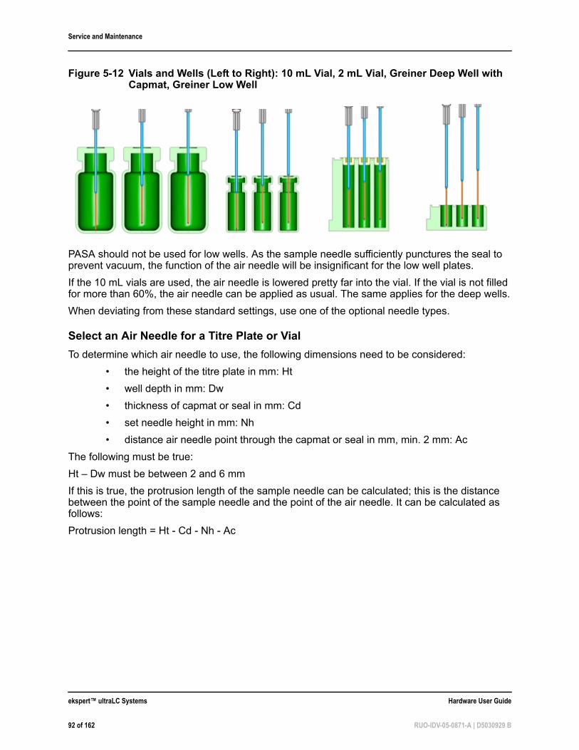
Service and Maintenance
PASA should not be used for low wells. As the sample needle sufficiently punctures the seal to prevent vacuum, the function of the air needle will be insignificant for the low well plates.
If the 10 mL vials are used, the air needle is lowered pretty far into the vial. If the vial is not filled for more than 60%, the air needle can be applied as usual. The same applies for the deep wells.
When deviating from these standard settings, use one of the optional needle types.
Select an Air Needle for a Titre Plate or Vial
To determine which air needle to use, the following dimensions need to be considered:
• the height of the titre plate in mm: Ht
• well depth in mm: Dw
• thickness of capmat or seal in mm: Cd
• set needle height in mm: Nh
• distance air needle point through the capmat or seal in mm, min. 2 mm: Ac
The following must be true:
Ht – Dw must be between 2 and 6 mm
If this is true, the protrusion length of the sample needle can be calculated; this is the distance between the point of the sample needle and the point of the air needle. It can be calculated as follows:
Protrusion length = Ht - Cd - Nh - Ac
Figure 5-12 Vials and Wells (Left to Right): 10 mL Vial, 2 mL Vial, Greiner Deep Well with Capmat, Greiner Low Well
ekspert™ ultraLC Systems Hardware User Guide
92 of 162 RUO-IDV-05-0871-A | D5030929 B
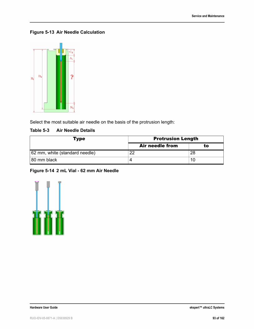
Service and Maintenance
Select the most suitable air needle on the basis of the protrusion length:
Figure 5-13 Air Needle Calculation
Table 5-3 Air Needle Details
Type Protrusion LengthAir needle from to
62 mm, white (standard needle) 22 28
80 mm black 4 10
Figure 5-14 2 mL Vial - 62 mm Air Needle
Hardware User Guide ekspert™ ultraLC Systems
RUO-IDV-05-0871-A | D5030929 B 93 of 162
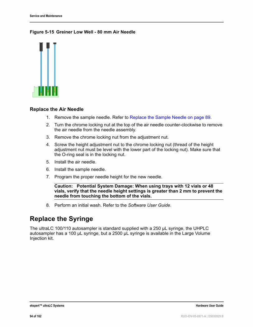
Service and Maintenance
Replace the Air Needle
1. Remove the sample needle. Refer to Replace the Sample Needle on page 89.
2. Turn the chrome locking nut at the top of the air needle counter-clockwise to remove the air needle from the needle assembly.
3. Remove the chrome locking nut from the adjustment nut.
4. Screw the height adjustment nut to the chrome locking nut (thread of the height adjustment nut must be level with the lower part of the locking nut). Make sure that the O-ring seal is in the locking nut.
5. Install the air needle.
6. Install the sample needle.
7. Program the proper needle height for the new needle.
Caution: Potential System Damage: When using trays with 12 vials or 48 vials, verify that the needle height settings is greater than 2 mm to prevent the needle from touching the bottom of the vials.
8. Perform an initial wash. Refer to the Software User Guide.
Replace the SyringeThe ultraLC 100/110 autosampler is standard supplied with a 250 µL syringe, the UHPLC autosampler has a 100 µL syringe, but a 2500 µL syringe is available in the Large Volume Injection kit.
Figure 5-15 Greiner Low Well - 80 mm Air Needle
ekspert™ ultraLC Systems Hardware User Guide
94 of 162 RUO-IDV-05-0871-A | D5030929 B
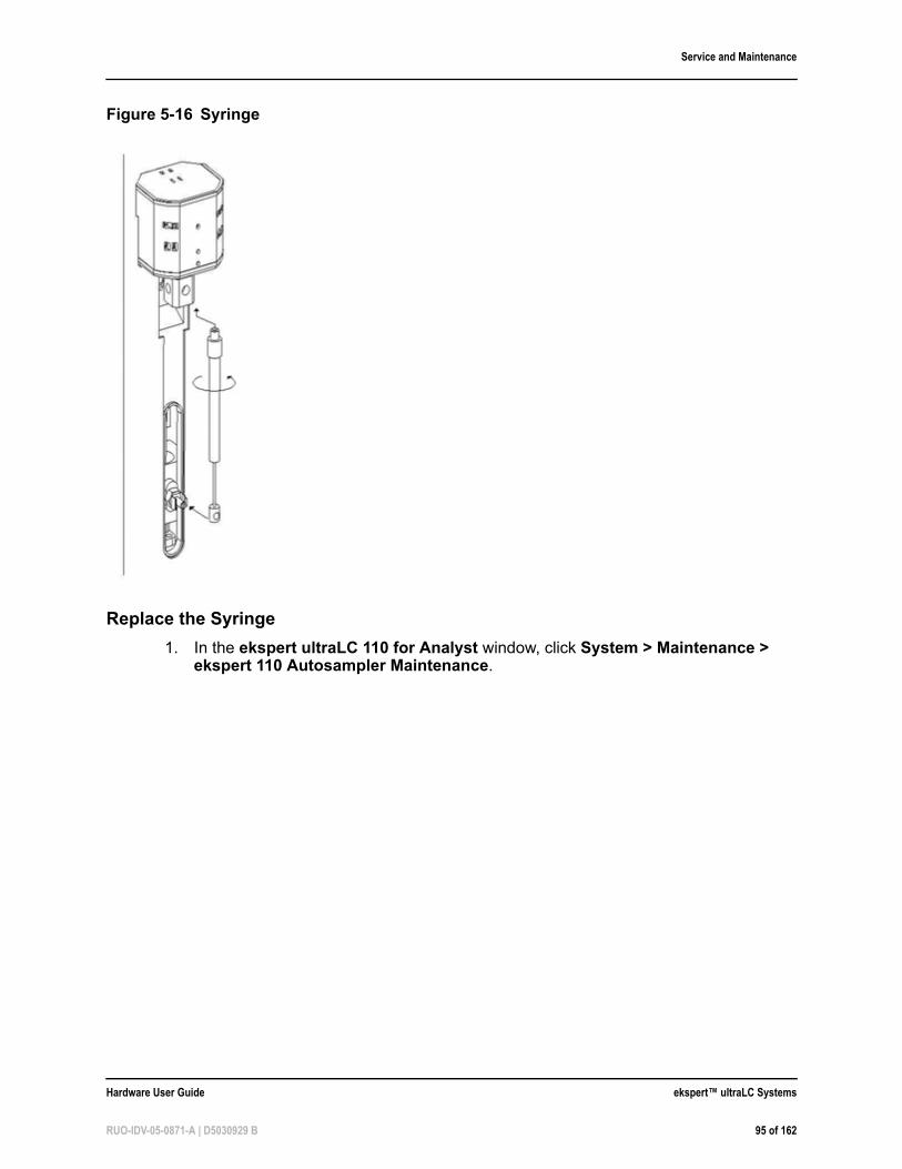
Service and Maintenance
Replace the Syringe
1. In the ekspert ultraLC 110 for Analyst window, click System > Maintenance > ekspert 110 Autosampler Maintenance.
Figure 5-16 Syringe
Hardware User Guide ekspert™ ultraLC Systems
RUO-IDV-05-0871-A | D5030929 B 95 of 162
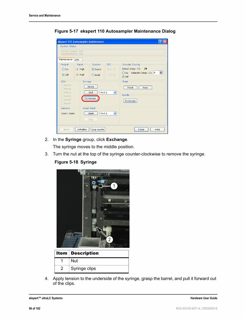
Service and Maintenance
2. In the Syringe group, click Exchange.
The syringe moves to the middle position.
3. Turn the nut at the top of the syringe counter-clockwise to remove the syringe.
4. Apply tension to the underside of the syringe, grasp the barrel, and pull it forward out of the clips.
Figure 5-17 ekspert 110 Autosampler Maintenance Dialog
Figure 5-18 Syringe
Item Description1 Nut
2 Syringe clips
2
1
ekspert™ ultraLC Systems Hardware User Guide
96 of 162 RUO-IDV-05-0871-A | D5030929 B
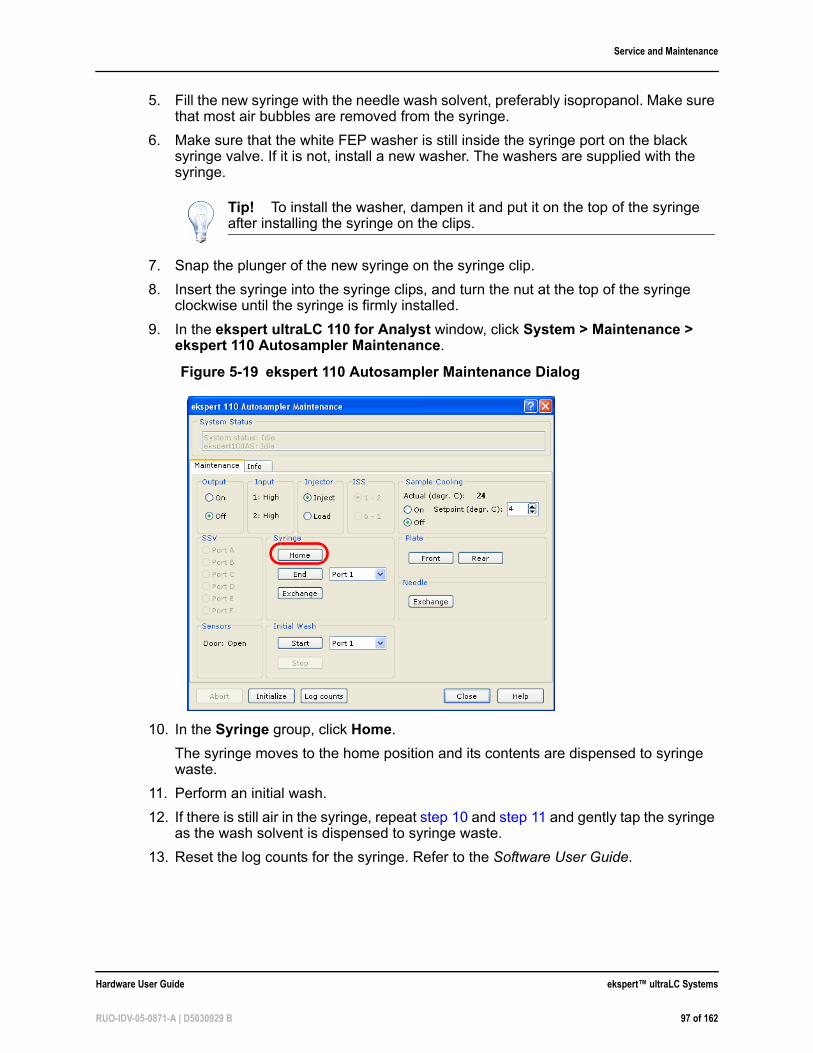
Service and Maintenance
5. Fill the new syringe with the needle wash solvent, preferably isopropanol. Make sure that most air bubbles are removed from the syringe.
6. Make sure that the white FEP washer is still inside the syringe port on the black syringe valve. If it is not, install a new washer. The washers are supplied with the syringe.
7. Snap the plunger of the new syringe on the syringe clip.
8. Insert the syringe into the syringe clips, and turn the nut at the top of the syringe clockwise until the syringe is firmly installed.
9. In the ekspert ultraLC 110 for Analyst window, click System > Maintenance > ekspert 110 Autosampler Maintenance.
10. In the Syringe group, click Home.
The syringe moves to the home position and its contents are dispensed to syringe waste.
11. Perform an initial wash.
12. If there is still air in the syringe, repeat step 10 and step 11 and gently tap the syringe as the wash solvent is dispensed to syringe waste.
13. Reset the log counts for the syringe. Refer to the Software User Guide.
Tip! To install the washer, dampen it and put it on the top of the syringe after installing the syringe on the clips.
Figure 5-19 ekspert 110 Autosampler Maintenance Dialog
Hardware User Guide ekspert™ ultraLC Systems
RUO-IDV-05-0871-A | D5030929 B 97 of 162
Service and Maintenance
Replace the Syringe Plunger and Plunger Tip
1. In Maintenance, click Exchange in the Syringe group box.
2. Remove the syringe. Refer to Replace the Syringe on page 94.
3. Slide the plunger out of the glass part of the syringe.
4. Use the pliers to remove the tip carefully. Be careful not to damage the stainless steel plunger.
5. Dampen the new tip, for example, with isopropanol.
6. Press the new tip on the plunger.
7. Insert the plunger in the glass part the syringe.
8. Install the syringe (Replace the Syringe on page 94) in the autosampler again.
Replace the Syringe ValveThe syringe valve is a 4-port selection valve. Ports are assigned as follows:
• Waste: Use this port as a drain for the syringe dispenser.
• Wash port 1: Use this port to aspirate wash liquid from the wash bottle (or in case of multiple wash liquids: connect it to the solvent selection valve)
• Needle: Connect the buffer tubing to this port
• Wash port 2: Optional syringe valve port
All connections to the syringe valve must be made with fingertight fittings. An exception can be made for the waste outlet (the port on the back of the valve).
Required Materials• Pliers
Prerequisite Procedures• Replace the Syringe on page 94
Required Materials• 2 mm hex screwdriver
Note: Put the syringe valve in Wash port 2 position before replacing the syringe valve. In this position, the mounting screws are opposite/in line with the holes.
ekspert™ ultraLC Systems Hardware User Guide
98 of 162 RUO-IDV-05-0871-A | D5030929 B
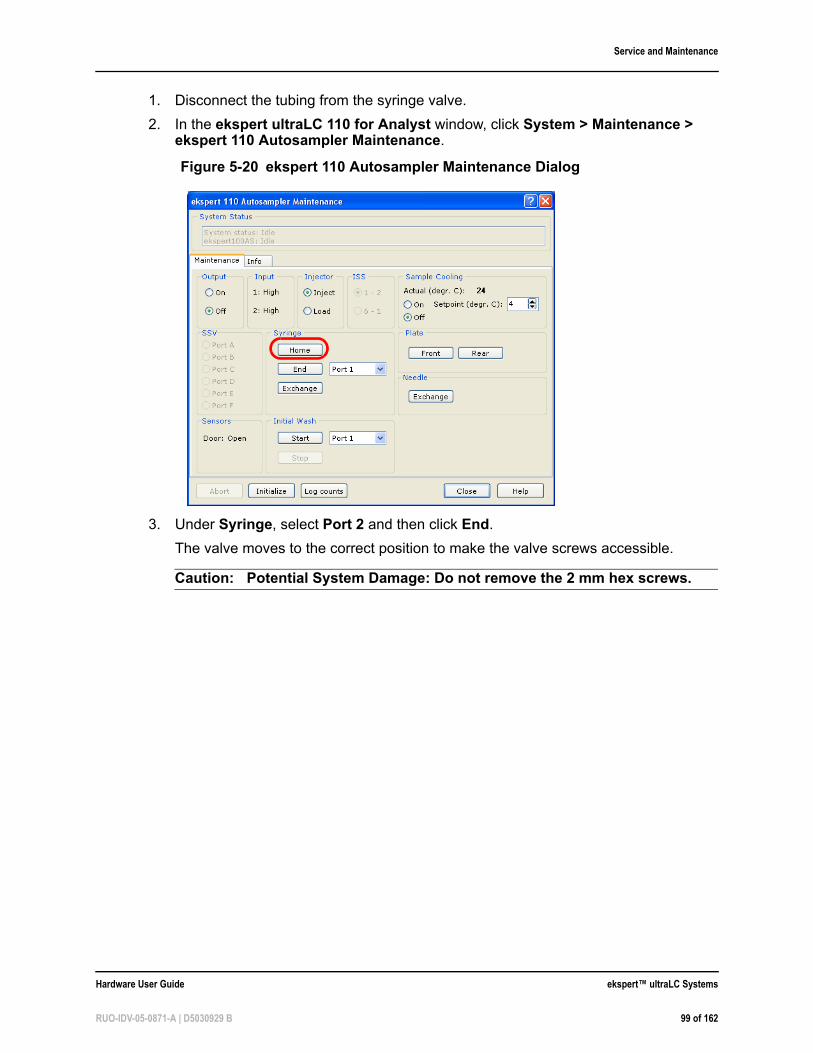
Service and Maintenance
1. Disconnect the tubing from the syringe valve.
2. In the ekspert ultraLC 110 for Analyst window, click System > Maintenance > ekspert 110 Autosampler Maintenance.
3. Under Syringe, select Port 2 and then click End.
The valve moves to the correct position to make the valve screws accessible.
Caution: Potential System Damage: Do not remove the 2 mm hex screws.
Figure 5-20 ekspert 110 Autosampler Maintenance Dialog
Hardware User Guide ekspert™ ultraLC Systems
RUO-IDV-05-0871-A | D5030929 B 99 of 162
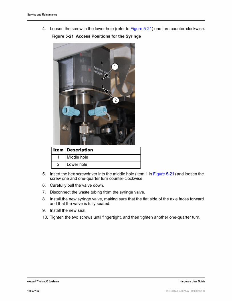
Service and Maintenance
4. Loosen the screw in the lower hole (refer to Figure 5-21) one turn counter-clockwise.
5. Insert the hex screwdriver into the middle hole (item 1 in Figure 5-21) and loosen the screw one and one-quarter turn counter-clockwise.
6. Carefully pull the valve down.
7. Disconnect the waste tubing from the syringe valve.
8. Install the new syringe valve, making sure that the flat side of the axle faces forward and that the valve is fully seated.
9. Install the new seal.
10. Tighten the two screws until fingertight, and then tighten another one-quarter turn.
Figure 5-21 Access Positions for the Syringe
Item Description1 Middle hole
2 Lower hole
2
1
ekspert™ ultraLC Systems Hardware User Guide
100 of 162 RUO-IDV-05-0871-A | D5030929 B
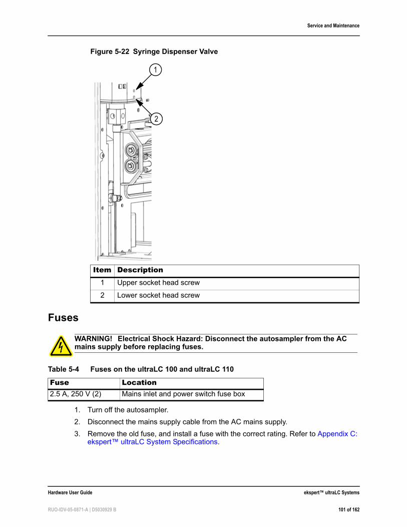
Service and Maintenance
Fuses
1. Turn off the autosampler.
2. Disconnect the mains supply cable from the AC mains supply.
3. Remove the old fuse, and install a fuse with the correct rating. Refer to Appendix C: ekspert™ ultraLC System Specifications.
Figure 5-22 Syringe Dispenser Valve
Item Description1 Upper socket head screw
2 Lower socket head screw
WARNING! Electrical Shock Hazard: Disconnect the autosampler from the AC mains supply before replacing fuses.
Table 5-4 Fuses on the ultraLC 100 and ultraLC 110
Fuse Location2.5 A, 250 V (2) Mains inlet and power switch fuse box
2
1
Hardware User Guide ekspert™ ultraLC Systems
RUO-IDV-05-0871-A | D5030929 B 101 of 162
Service and Maintenance
ekspert ultraLC 100-XL/110-XL Autosampler
Regularly clean and maintain the autosampler to keep it functioning optimally. In addition, regular maintenance is required. This section includes basic maintenance procedures that may be performed by the customer.
Contact the manufacturer if the autosampler:
• Has been subjected to severe shock or if liquid has been spilled into the system
• Does not operate as specified or if it shows a change in performance.
Prepare for Maintenance1. Open the front door. Refer to Open the Front Cover on page 66.
2. Remove the bottom front cover. Refer to Remove the Bottom Front Cover on page 67.
Maintain the Waste TubingThe waste tubing drains fluids from the drip tray under the wash station. It is accessible from inside the autosampler. If dirt accumulates below the sample tray, the waste tubing might be dirty or clogged, and should be cleaned.
Clean the Drip Tray
• Remove the drip tray to clean it.
Remove the Waste Tubing
Note: Contact an AB SCIEX FSE if issues with fuses are recurring.
WARNING! Potential System Damage: Do not service the system beyond the scope of maintenance described in this section. Maintenance procedures not described in this section should be completed by an FSE.
Note: After changing the physical configuration of the autosampler, reconfigure it in the ekspert ultraLC 110-XL software.
Note: You do not need no disconnect the ultraLC 100-XL/110-XL autosampler from the power source for most of the maintenance procedures. In this way software control will still be possible.Turn off the autosampler when replacing the puncturing air needle.
Required materials• Phillips screwdriver
ekspert™ ultraLC Systems Hardware User Guide
102 of 162 RUO-IDV-05-0871-A | D5030929 B
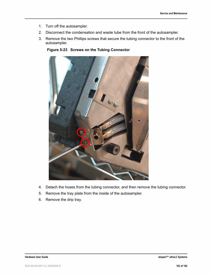
Service and Maintenance
1. Turn off the autosampler.
2. Disconnect the condensation and waste tube from the front of the autosampler.
3. Remove the two Phillips screws that secure the tubing connector to the front of the autosampler.
4. Detach the hoses from the tubing connector, and then remove the tubing connector.
5. Remove the tray plate from the inside of the autosampler.
6. Remove the drip tray.
Figure 5-23 Screws on the Tubing Connector
Hardware User Guide ekspert™ ultraLC Systems
RUO-IDV-05-0871-A | D5030929 B 103 of 162
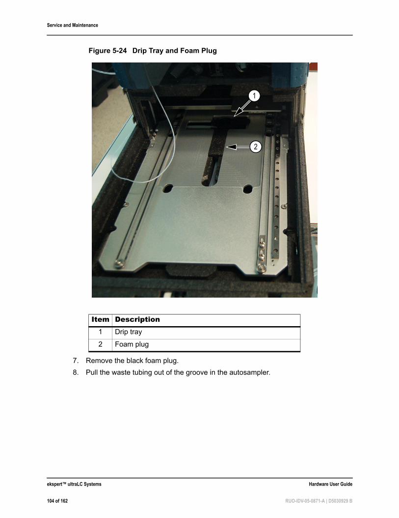
Service and Maintenance
7. Remove the black foam plug.
8. Pull the waste tubing out of the groove in the autosampler.
Figure 5-24 Drip Tray and Foam Plug
Item Description1 Drip tray
2 Foam plug
2
1
ekspert™ ultraLC Systems Hardware User Guide
104 of 162 RUO-IDV-05-0871-A | D5030929 B
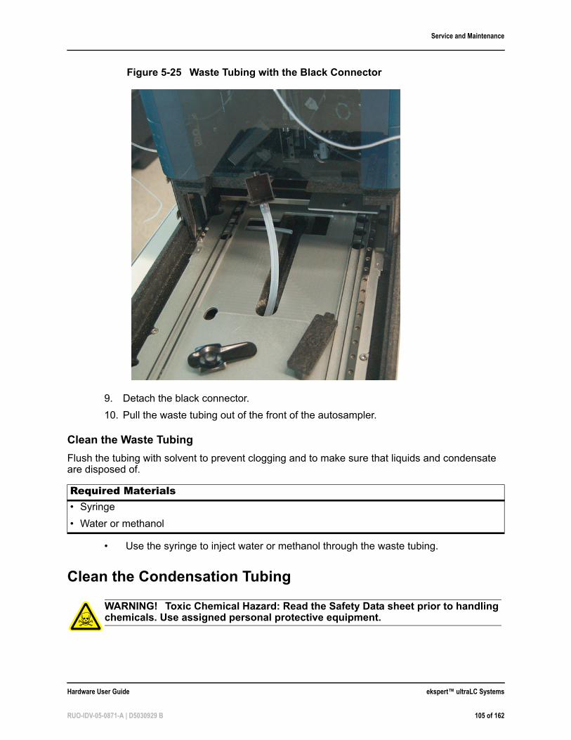
Service and Maintenance
9. Detach the black connector.
10. Pull the waste tubing out of the front of the autosampler.
Clean the Waste Tubing
Flush the tubing with solvent to prevent clogging and to make sure that liquids and condensate are disposed of.
• Use the syringe to inject water or methanol through the waste tubing.
Clean the Condensation Tubing
Figure 5-25 Waste Tubing with the Black Connector
Required Materials• Syringe
• Water or methanol
WARNING! Toxic Chemical Hazard: Read the Safety Data sheet prior to handling chemicals. Use assigned personal protective equipment.
Hardware User Guide ekspert™ ultraLC Systems
RUO-IDV-05-0871-A | D5030929 B 105 of 162

Service and Maintenance
The condensation tubing drains fluids from the bottom of the autosampler. It is accessible under the autosampler.
1. Turn off the autosampler.
2. If required, remove any vial adapters and well plates in the autosampler.
3. Carefully turn the autosampler on to its side.
4. Disconnect the condensation/waste tube from the front of the autosampler.
5. Remove the two Phillips screws that secure the tubing connector to the front of the autosampler. Refer to Figure 5-23.
6. Detach the hoses from the tubing connector, and then remove the tubing connector.
7. Remove the foam plug on the bottom of the autosampler.
8. Pull the condensation tubing out through the grove in the bottom of the autosampler.
Required Materials• Phillips screwdriver
• Syringe
• Water or methanol
Figure 5-26 Black Foam Plug Removed
ekspert™ ultraLC Systems Hardware User Guide
106 of 162 RUO-IDV-05-0871-A | D5030929 B
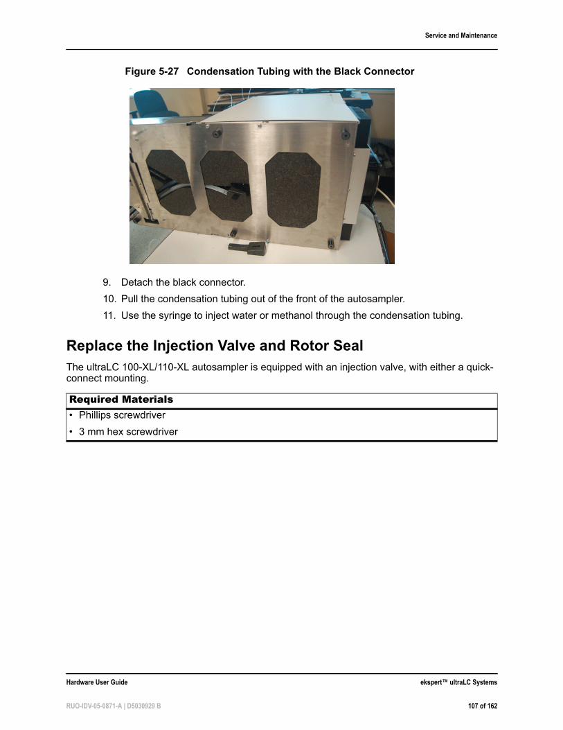
Service and Maintenance
9. Detach the black connector.
10. Pull the condensation tubing out of the front of the autosampler.
11. Use the syringe to inject water or methanol through the condensation tubing.
Replace the Injection Valve and Rotor SealThe ultraLC 100-XL/110-XL autosampler is equipped with an injection valve, with either a quick-connect mounting.
Figure 5-27 Condensation Tubing with the Black Connector
Required Materials• Phillips screwdriver
• 3 mm hex screwdriver
Hardware User Guide ekspert™ ultraLC Systems
RUO-IDV-05-0871-A | D5030929 B 107 of 162
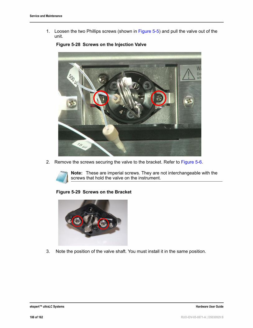
Service and Maintenance
1. Loosen the two Phillips screws (shown in Figure 5-5) and pull the valve out of the unit.
2. Remove the screws securing the valve to the bracket. Refer to Figure 5-6.
3. Note the position of the valve shaft. You must install it in the same position.
Figure 5-28 Screws on the Injection Valve
Note: These are imperial screws. They are not interchangeable with the screws that hold the valve on the instrument.
Figure 5-29 Screws on the Bracket
ekspert™ ultraLC Systems Hardware User Guide
108 of 162 RUO-IDV-05-0871-A | D5030929 B
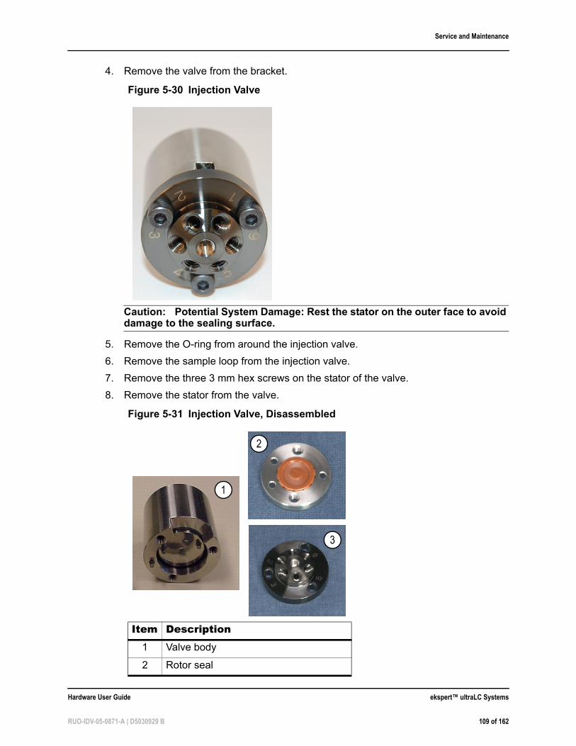
Service and Maintenance
4. Remove the valve from the bracket.
Caution: Potential System Damage: Rest the stator on the outer face to avoid damage to the sealing surface.
5. Remove the O-ring from around the injection valve.
6. Remove the sample loop from the injection valve.
7. Remove the three 3 mm hex screws on the stator of the valve.
8. Remove the stator from the valve.
Figure 5-30 Injection Valve
Figure 5-31 Injection Valve, Disassembled
Item Description1 Valve body
2 Rotor seal
2
1
3
Hardware User Guide ekspert™ ultraLC Systems
RUO-IDV-05-0871-A | D5030929 B 109 of 162
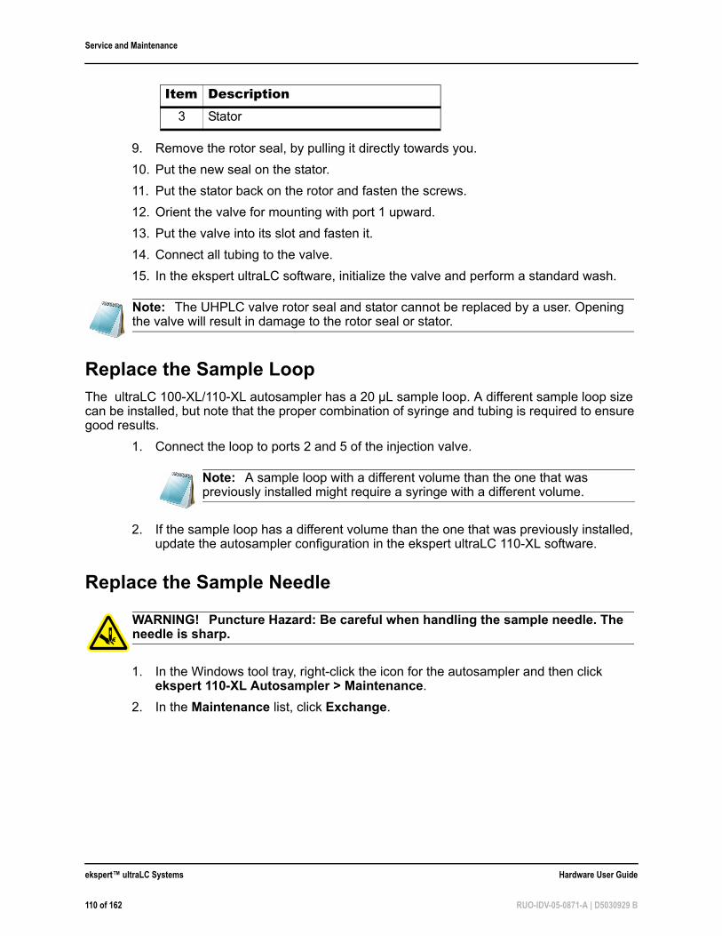
Service and Maintenance
9. Remove the rotor seal, by pulling it directly towards you.
10. Put the new seal on the stator.
11. Put the stator back on the rotor and fasten the screws.
12. Orient the valve for mounting with port 1 upward.
13. Put the valve into its slot and fasten it.
14. Connect all tubing to the valve.
15. In the ekspert ultraLC software, initialize the valve and perform a standard wash.
Replace the Sample LoopThe ultraLC 100-XL/110-XL autosampler has a 20 µL sample loop. A different sample loop size can be installed, but note that the proper combination of syringe and tubing is required to ensure good results.
1. Connect the loop to ports 2 and 5 of the injection valve.
2. If the sample loop has a different volume than the one that was previously installed, update the autosampler configuration in the ekspert ultraLC 110-XL software.
Replace the Sample Needle
1. In the Windows tool tray, right-click the icon for the autosampler and then click ekspert 110-XL Autosampler > Maintenance.
2. In the Maintenance list, click Exchange.
3 Stator
Note: The UHPLC valve rotor seal and stator cannot be replaced by a user. Opening the valve will result in damage to the rotor seal or stator.
Note: A sample loop with a different volume than the one that was previously installed might require a syringe with a different volume.
WARNING! Puncture Hazard: Be careful when handling the sample needle. The needle is sharp.
Item Description
ekspert™ ultraLC Systems Hardware User Guide
110 of 162 RUO-IDV-05-0871-A | D5030929 B
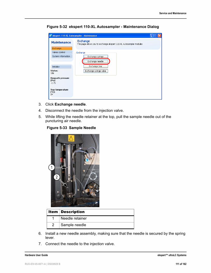
Service and Maintenance
3. Click Exchange needle.
4. Disconnect the needle from the injection valve.
5. While lifting the needle retainer at the top, pull the sample needle out of the puncturing air needle.
6. Install a new needle assembly, making sure that the needle is secured by the spring lever.
7. Connect the needle to the injection valve.
Figure 5-32 ekspert 110-XL Autosampler - Maintenance Dialog
Figure 5-33 Sample Needle
Item Description1 Needle retainer
2 Sample needle
2
1
Hardware User Guide ekspert™ ultraLC Systems
RUO-IDV-05-0871-A | D5030929 B 111 of 162
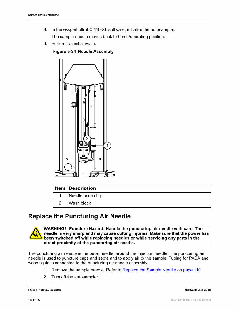
Service and Maintenance
8. In the ekspert ultraLC 110-XL software, initialize the autosampler.
The sample needle moves back to home/operating position.
9. Perform an initial wash.
Replace the Puncturing Air Needle
The puncturing air needle is the outer needle, around the injection needle. The puncturing air needle is used to puncture caps and septa and to apply air to the sample. Tubing for PASA and wash liquid is connected to the puncturing air needle assembly.
1. Remove the sample needle. Refer to Replace the Sample Needle on page 110.
2. Turn off the autosampler.
Figure 5-34 Needle Assembly
Item Description1 Needle assembly
2 Wash block
WARNING! Puncture Hazard: Handle the puncturing air needle with care. The needle is very sharp and may cause cutting injuries. Make sure that the power has been switched off while replacing needles or while servicing any parts in the direct proximity of the puncturing air needle.
2
1
ekspert™ ultraLC Systems Hardware User Guide
112 of 162 RUO-IDV-05-0871-A | D5030929 B
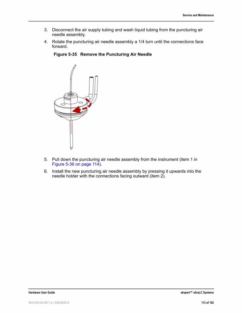
Service and Maintenance
3. Disconnect the air supply tubing and wash liquid tubing from the puncturing air needle assembly.
4. Rotate the puncturing air needle assembly a 1/4 turn until the connections face forward.
5. Pull down the puncturing air needle assembly from the instrument (item 1 in Figure 5-36 on page 114).
6. Install the new puncturing air needle assembly by pressing it upwards into the needle holder with the connections facing outward (item 2).
Figure 5-35 Remove the Puncturing Air Needle
Hardware User Guide ekspert™ ultraLC Systems
RUO-IDV-05-0871-A | D5030929 B 113 of 162
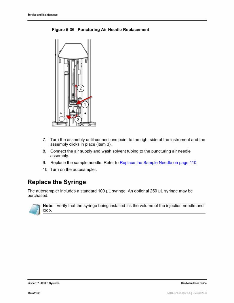
Service and Maintenance
7. Turn the assembly until connections point to the right side of the instrument and the assembly clicks in place (item 3).
8. Connect the air supply and wash solvent tubing to the puncturing air needle assembly.
9. Replace the sample needle. Refer to Replace the Sample Needle on page 110.
10. Turn on the autosampler.
Replace the SyringeThe autosampler includes a standard 100 µL syringe. An optional 250 µL syringe may be purchased.
Figure 5-36 Puncturing Air Needle Replacement
Note: Verify that the syringe being installed fits the volume of the injection needle and loop.
3
1
2
ekspert™ ultraLC Systems Hardware User Guide
114 of 162 RUO-IDV-05-0871-A | D5030929 B
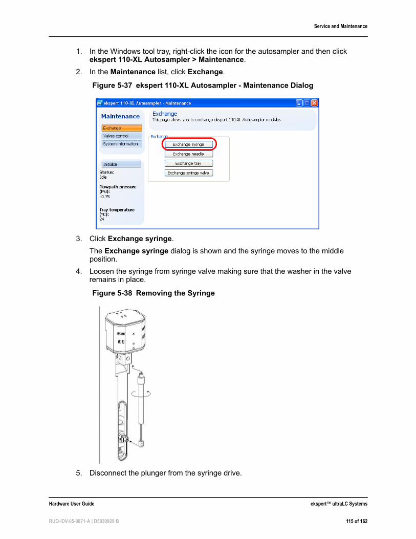
Service and Maintenance
1. In the Windows tool tray, right-click the icon for the autosampler and then click ekspert 110-XL Autosampler > Maintenance.
2. In the Maintenance list, click Exchange.
3. Click Exchange syringe.
The Exchange syringe dialog is shown and the syringe moves to the middle position.
4. Loosen the syringe from syringe valve making sure that the washer in the valve remains in place.
5. Disconnect the plunger from the syringe drive.
Figure 5-37 ekspert 110-XL Autosampler - Maintenance Dialog
Figure 5-38 Removing the Syringe
Hardware User Guide ekspert™ ultraLC Systems
RUO-IDV-05-0871-A | D5030929 B 115 of 162
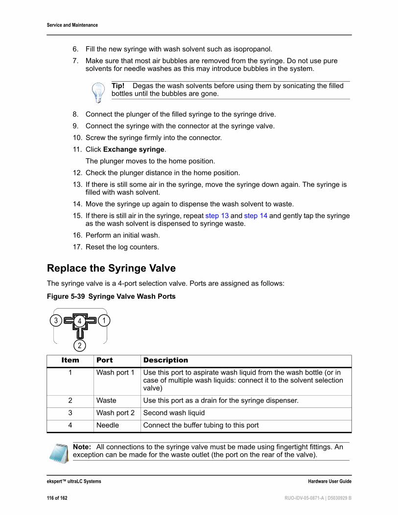
Service and Maintenance
6. Fill the new syringe with wash solvent such as isopropanol.
7. Make sure that most air bubbles are removed from the syringe. Do not use pure solvents for needle washes as this may introduce bubbles in the system.
8. Connect the plunger of the filled syringe to the syringe drive.
9. Connect the syringe with the connector at the syringe valve.
10. Screw the syringe firmly into the connector.
11. Click Exchange syringe.
The plunger moves to the home position.
12. Check the plunger distance in the home position.
13. If there is still some air in the syringe, move the syringe down again. The syringe is filled with wash solvent.
14. Move the syringe up again to dispense the wash solvent to waste.
15. If there is still air in the syringe, repeat step 13 and step 14 and gently tap the syringe as the wash solvent is dispensed to syringe waste.
16. Perform an initial wash.
17. Reset the log counters.
Replace the Syringe ValveThe syringe valve is a 4-port selection valve. Ports are assigned as follows:
Tip! Degas the wash solvents before using them by sonicating the filled bottles until the bubbles are gone.
Figure 5-39 Syringe Valve Wash Ports
Item Port Description1 Wash port 1 Use this port to aspirate wash liquid from the wash bottle (or in
case of multiple wash liquids: connect it to the solvent selection valve)
2 Waste Use this port as a drain for the syringe dispenser.
3 Wash port 2 Second wash liquid
4 Needle Connect the buffer tubing to this port
Note: All connections to the syringe valve must be made using fingertight fittings. An exception can be made for the waste outlet (the port on the rear of the valve).
13
2
4
ekspert™ ultraLC Systems Hardware User Guide
116 of 162 RUO-IDV-05-0871-A | D5030929 B
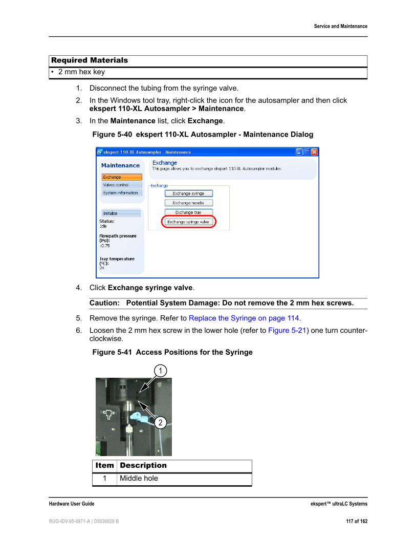
Service and Maintenance
1. Disconnect the tubing from the syringe valve.
2. In the Windows tool tray, right-click the icon for the autosampler and then click ekspert 110-XL Autosampler > Maintenance.
3. In the Maintenance list, click Exchange.
4. Click Exchange syringe valve.
Caution: Potential System Damage: Do not remove the 2 mm hex screws.
5. Remove the syringe. Refer to Replace the Syringe on page 114.
6. Loosen the 2 mm hex screw in the lower hole (refer to Figure 5-21) one turn counter-clockwise.
Required Materials• 2 mm hex key
Figure 5-40 ekspert 110-XL Autosampler - Maintenance Dialog
Figure 5-41 Access Positions for the Syringe
Item Description1 Middle hole
2
1
Hardware User Guide ekspert™ ultraLC Systems
RUO-IDV-05-0871-A | D5030929 B 117 of 162
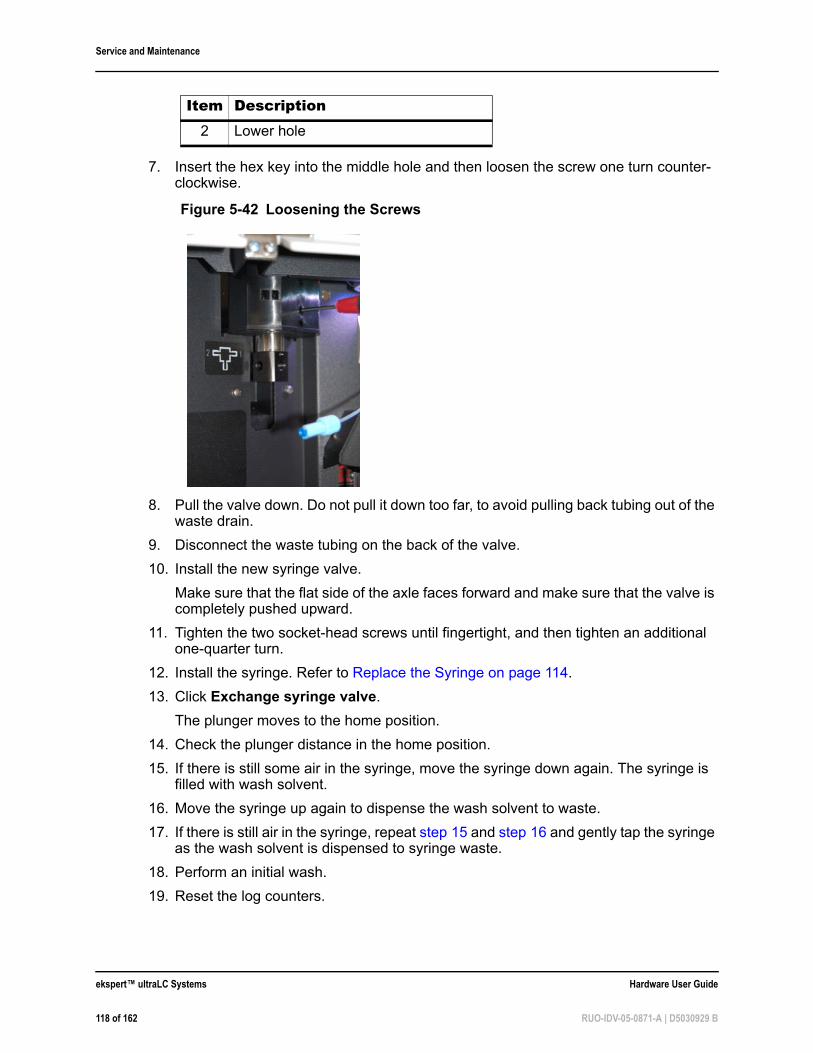
Service and Maintenance
7. Insert the hex key into the middle hole and then loosen the screw one turn counter-clockwise.
8. Pull the valve down. Do not pull it down too far, to avoid pulling back tubing out of the waste drain.
9. Disconnect the waste tubing on the back of the valve.
10. Install the new syringe valve.
Make sure that the flat side of the axle faces forward and make sure that the valve is completely pushed upward.
11. Tighten the two socket-head screws until fingertight, and then tighten an additional one-quarter turn.
12. Install the syringe. Refer to Replace the Syringe on page 114.
13. Click Exchange syringe valve.
The plunger moves to the home position.
14. Check the plunger distance in the home position.
15. If there is still some air in the syringe, move the syringe down again. The syringe is filled with wash solvent.
16. Move the syringe up again to dispense the wash solvent to waste.
17. If there is still air in the syringe, repeat step 15 and step 16 and gently tap the syringe as the wash solvent is dispensed to syringe waste.
18. Perform an initial wash.
19. Reset the log counters.
2 Lower hole
Figure 5-42 Loosening the Screws
Item Description
ekspert™ ultraLC Systems Hardware User Guide
118 of 162 RUO-IDV-05-0871-A | D5030929 B
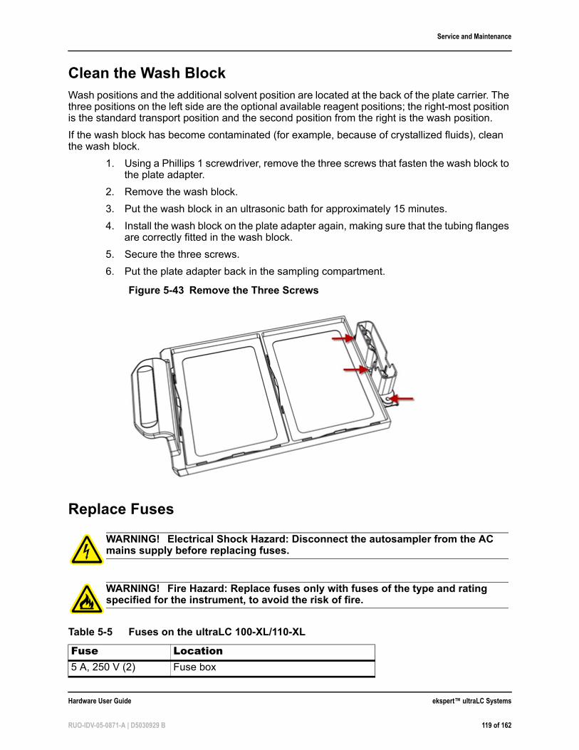
Service and Maintenance
Clean the Wash BlockWash positions and the additional solvent position are located at the back of the plate carrier. The three positions on the left side are the optional available reagent positions; the right-most position is the standard transport position and the second position from the right is the wash position.
If the wash block has become contaminated (for example, because of crystallized fluids), clean the wash block.
1. Using a Phillips 1 screwdriver, remove the three screws that fasten the wash block to the plate adapter.
2. Remove the wash block.
3. Put the wash block in an ultrasonic bath for approximately 15 minutes.
4. Install the wash block on the plate adapter again, making sure that the tubing flanges are correctly fitted in the wash block.
5. Secure the three screws.
6. Put the plate adapter back in the sampling compartment.
Replace Fuses
Figure 5-43 Remove the Three Screws
WARNING! Electrical Shock Hazard: Disconnect the autosampler from the AC mains supply before replacing fuses.
WARNING! Fire Hazard: Replace fuses only with fuses of the type and rating specified for the instrument, to avoid the risk of fire.
Table 5-5 Fuses on the ultraLC 100-XL/110-XL
Fuse Location5 A, 250 V (2) Fuse box
Hardware User Guide ekspert™ ultraLC Systems
RUO-IDV-05-0871-A | D5030929 B 119 of 162
Service and Maintenance
1. Turn off the autosampler.
2. Disconnect the mains supply cable from the AC mains supply.
3. Use a flat-bladed screwdriver to pry out the fuse box.
4. Remove the old fuse, and install a fuse with the correct rating. Refer to Appendix C: ekspert™ ultraLC System Specifications.
Prepare the Autosampler for Long-Term StorageIf the autosampler needs to be stored for a long time, or if it must be shipped to a different location, follow these steps:
1. Thoroughly flush the system.
2. Disconnect and remove all tubing, except for the sample loop.
3. Turn off the autosampler.
Prepare the Autosampler for Transport
1. Remove and dispose of the needle and other flow path materials, in accordance with an approved waste disposal program.
Caution: Potential System Damage: If the original packing materials are not available, wrap the autosampler in several layers in bubble wrap and cushion the bottom, top and all four sides with 5 cm of packaging foam. Since an autosampler is a delicate instrument, it must be packaged carefully and handled with care to protect it against shocks and vibrations during shipment.
2. Pack the autosampler in the original packaging.
3. Put the foam block in the tray location.
4. Complete a Certificate of Instrument Decontamination form for the instrument and include the form in the package.
5. Make sure any tax, import, and export requirements are met.
Note: Contact an AB SCIEX FSE if issues with fuses are recurring.
Prerequisite Procedures• Prepare the Autosampler for Long-Term Storage on page 120
ekspert™ ultraLC Systems Hardware User Guide
120 of 162 RUO-IDV-05-0871-A | D5030929 B
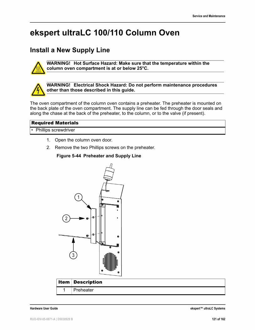
Service and Maintenance
ekspert ultraLC 100/110 Column Oven
Install a New Supply Line
The oven compartment of the column oven contains a preheater. The preheater is mounted on the back plate of the oven compartment. The supply line can be fed through the door seals and along the chase at the back of the preheater, to the column, or to the valve (if present).
1. Open the column oven door.
2. Remove the two Phillips screws on the preheater.
WARNING! Hot Surface Hazard: Make sure that the temperature within the column oven compartment is at or below 25°C.
WARNING! Electrical Shock Hazard: Do not perform maintenance procedures other than those described in this guide.
Required Materials• Phillips screwdriver
Figure 5-44 Preheater and Supply Line
Item Description1 Preheater
1
3
2
Hardware User Guide ekspert™ ultraLC Systems
RUO-IDV-05-0871-A | D5030929 B 121 of 162
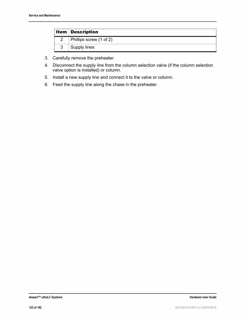
Service and Maintenance
3. Carefully remove the preheater.
4. Disconnect the supply line from the column selection valve (if the column selection valve option is installed) or column.
5. Install a new supply line and connect it to the valve or column.
6. Feed the supply line along the chase in the preheater.
2 Phillips screw (1 of 2)
3 Supply lines
Item Description
ekspert™ ultraLC Systems Hardware User Guide
122 of 162 RUO-IDV-05-0871-A | D5030929 B
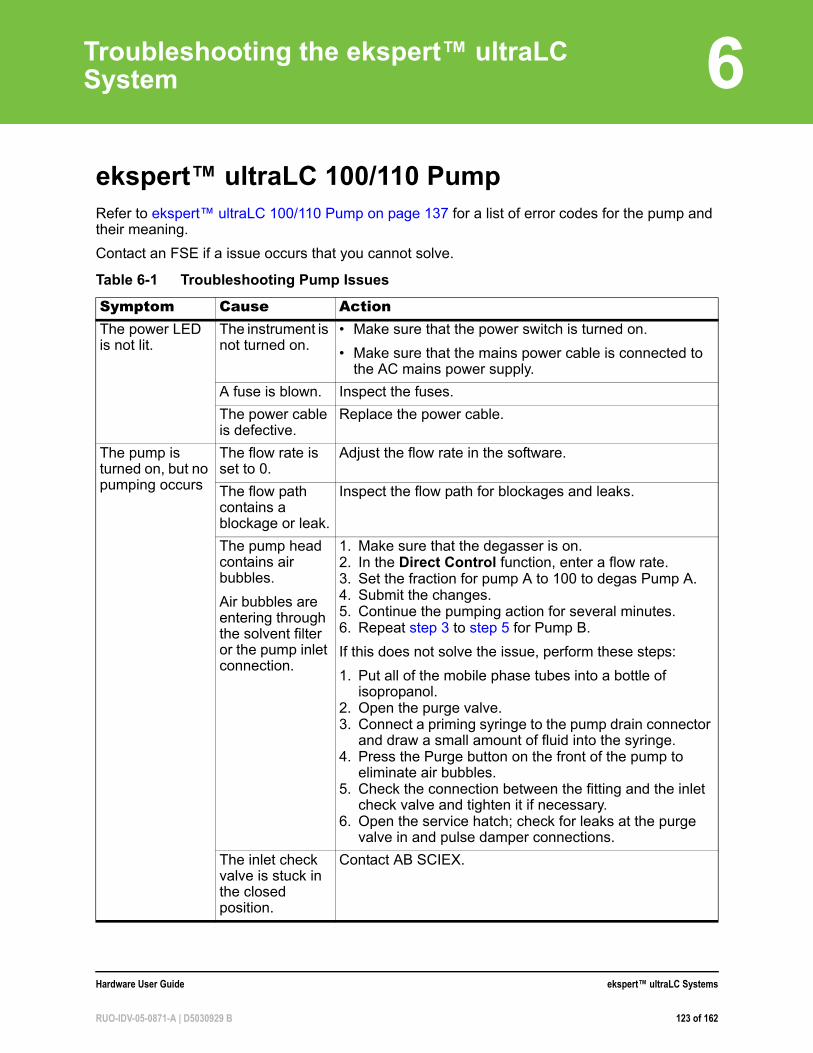
6
Troubleshooting the ekspert™ ultraLC Systemekspert™ ultraLC 100/110 PumpRefer to ekspert™ ultraLC 100/110 Pump on page 137 for a list of error codes for the pump and their meaning.
Contact an FSE if a issue occurs that you cannot solve.
Table 6-1 Troubleshooting Pump Issues
Symptom Cause ActionThe power LED is not lit.
The instrument is not turned on.
• Make sure that the power switch is turned on.
• Make sure that the mains power cable is connected to the AC mains power supply.
A fuse is blown. Inspect the fuses.
The power cable is defective.
Replace the power cable.
The pump is turned on, but no pumping occurs
The flow rate is set to 0.
Adjust the flow rate in the software.
The flow path contains a blockage or leak.
Inspect the flow path for blockages and leaks.
The pump head contains air bubbles.
Air bubbles are entering through the solvent filter or the pump inlet connection.
1. Make sure that the degasser is on.2. In the Direct Control function, enter a flow rate. 3. Set the fraction for pump A to 100 to degas Pump A.4. Submit the changes. 5. Continue the pumping action for several minutes. 6. Repeat step 3 to step 5 for Pump B.
If this does not solve the issue, perform these steps:
1. Put all of the mobile phase tubes into a bottle of isopropanol.
2. Open the purge valve.3. Connect a priming syringe to the pump drain connector
and draw a small amount of fluid into the syringe. 4. Press the Purge button on the front of the pump to
eliminate air bubbles. 5. Check the connection between the fitting and the inlet
check valve and tighten it if necessary.6. Open the service hatch; check for leaks at the purge
valve in and pulse damper connections.
The inlet check valve is stuck in the closed position.
Contact AB SCIEX.
Hardware User Guide ekspert™ ultraLC Systems
RUO-IDV-05-0871-A | D5030929 B 123 of 162
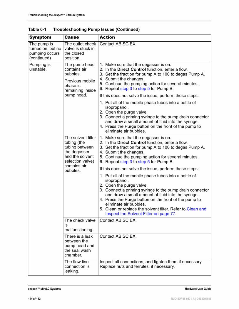
Troubleshooting the ekspert™ ultraLC System
The pump is turned on, but no pumping occurs (continued)
The outlet check valve is stuck in the closed position.
Contact AB SCIEX.
Pumping is unstable.
The pump head contains air bubbles.
Previous mobile phase is remaining inside pump head.
1. Make sure that the degasser is on.2. In the Direct Control function, enter a flow. 3. Set the fraction for pump A to 100 to degas Pump A.4. Submit the changes. 5. Continue the pumping action for several minutes. 6. Repeat step 3 to step 5 for Pump B.
If this does not solve the issue, perform these steps:
1. Put all of the mobile phase tubes into a bottle of isopropanol.
2. Open the purge valve.3. Connect a priming syringe to the pump drain connector
and draw a small amount of fluid into the syringe. 4. Press the Purge button on the front of the pump to
eliminate air bubbles.
The solvent filter tubing (the tubing between the degasser and the solvent selection valve) contains air bubbles.
1. Make sure that the degasser is on.2. In the Direct Control function, enter a flow. 3. Set the fraction for pump A to 100 to degas Pump A.4. Submit the changes. 5. Continue the pumping action for several minutes. 6. Repeat step 3 to step 5 for Pump B.
If this does not solve the issue, perform these steps:
1. Put all of the mobile phase tubes into a bottle of isopropanol.
2. Open the purge valve.3. Connect a priming syringe to the pump drain connector
and draw a small amount of fluid into the syringe. 4. Press the Purge button on the front of the pump to
eliminate air bubbles. 5. Clean or replace the solvent filter. Refer to Clean and
Inspect the Solvent Filter on page 77.
The check valve is malfunctioning.
Contact AB SCIEX.
There is a leak between the pump head and the seal wash chamber.
Contact AB SCIEX.
The flow line connection is leaking.
Inspect all connections, and tighten them if necessary. Replace nuts and ferrules, if necessary.
Table 6-1 Troubleshooting Pump Issues (Continued)
Symptom Cause Action
ekspert™ ultraLC Systems Hardware User Guide
124 of 162 RUO-IDV-05-0871-A | D5030929 B
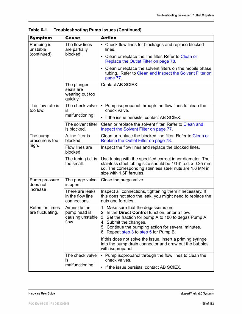
Troubleshooting the ekspert™ ultraLC System
Pumping is unstable (continued).
The flow lines are partially blocked.
• Check flow lines for blockages and replace blocked lines.
• Clean or replace the line filter. Refer to Clean or Replace the Outlet Filter on page 78.
• Clean or replace the solvent filters on the mobile phase tubing. Refer to Clean and Inspect the Solvent Filter on page 77.
The plunger seals are wearing out too quickly.
Contact AB SCIEX.
The flow rate is too low.
The check valve is malfunctioning.
• Pump isopropanol through the flow lines to clean the check valve.
• If the issue persists, contact AB SCIEX.
The solvent filter is blocked.
Clean or replace the solvent filter. Refer to Clean and Inspect the Solvent Filter on page 77.
The pump pressure is too high.
A line filter is blocked.
Clean or replace the blocked line filter. Refer to Clean or Replace the Outlet Filter on page 78.
Flow lines are blocked.
Inspect the flow lines and replace the blocked lines.
The tubing i.d. is too small.
Use tubing with the specified correct inner diameter. The stainless steel tubing size should be 1/16" o.d. x 0.25 mm i.d. The corresponding stainless steel nuts are 1.6 MN in size with 1.6F ferrules.
Pump pressure does not increase
The purge valve is open.
Close the purge valve.
There are leaks in the flow line connections.
Inspect all connections, tightening them if necessary. If this does not stop the leak, you might need to replace the nuts and ferrules.
Retention times are fluctuating.
Air inside the pump head is causing unstable flow.
1. Make sure that the degasser is on.2. In the Direct Control function, enter a flow. 3. Set the fraction for pump A to 100 to degas Pump A.4. Submit the changes. 5. Continue the pumping action for several minutes. 6. Repeat step 3 to step 5 for Pump B.
If this does not solve the issue, insert a priming syringe into the pump drain connector and draw out the bubbles with isopropanol.
The check valve is malfunctioning.
• Pump isopropanol through the flow lines to clean the check valves.
• If the issue persists, contact AB SCIEX.
Table 6-1 Troubleshooting Pump Issues (Continued)
Symptom Cause Action
Hardware User Guide ekspert™ ultraLC Systems
RUO-IDV-05-0871-A | D5030929 B 125 of 162
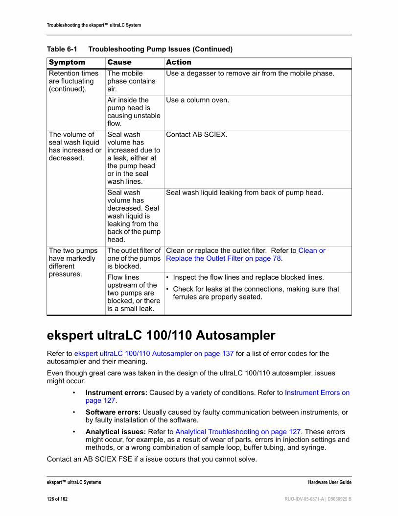
Troubleshooting the ekspert™ ultraLC System
ekspert ultraLC 100/110 AutosamplerRefer to ekspert ultraLC 100/110 Autosampler on page 137 for a list of error codes for the autosampler and their meaning.
Even though great care was taken in the design of the ultraLC 100/110 autosampler, issues might occur:
• Instrument errors: Caused by a variety of conditions. Refer to Instrument Errors on page 127.
• Software errors: Usually caused by faulty communication between instruments, or by faulty installation of the software.
• Analytical issues: Refer to Analytical Troubleshooting on page 127. These errors might occur, for example, as a result of wear of parts, errors in injection settings and methods, or a wrong combination of sample loop, buffer tubing, and syringe.
Contact an AB SCIEX FSE if a issue occurs that you cannot solve.
Retention times are fluctuating (continued).
The mobile phase contains air.
Use a degasser to remove air from the mobile phase.
Air inside the pump head is causing unstable flow.
Use a column oven.
The volume of seal wash liquid has increased or decreased.
Seal wash volume has increased due to a leak, either at the pump head or in the seal wash lines.
Contact AB SCIEX.
Seal wash volume has decreased. Seal wash liquid is leaking from the back of the pump head.
Seal wash liquid leaking from back of pump head.
The two pumps have markedly different pressures.
The outlet filter of one of the pumps is blocked.
Clean or replace the outlet filter. Refer to Clean or Replace the Outlet Filter on page 78.
Flow lines upstream of the two pumps are blocked, or there is a small leak.
• Inspect the flow lines and replace blocked lines.
• Check for leaks at the connections, making sure that ferrules are properly seated.
Table 6-1 Troubleshooting Pump Issues (Continued)
Symptom Cause Action
ekspert™ ultraLC Systems Hardware User Guide
126 of 162 RUO-IDV-05-0871-A | D5030929 B
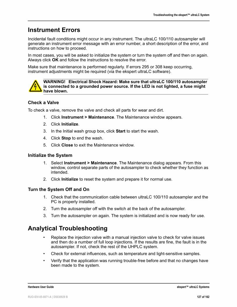
Troubleshooting the ekspert™ ultraLC System
Instrument ErrorsIncidental fault conditions might occur in any instrument. The ultraLC 100/110 autosampler will generate an instrument error message with an error number, a short description of the error, and instructions on how to proceed.
In most cases, you will be asked to initialize the system or turn the system off and then on again. Always click OK and follow the instructions to resolve the error.
Make sure that maintenance is performed regularly. If errors 295 or 308 keep occurring, instrument adjustments might be required (via the ekspert ultraLC software).
Check a Valve
To check a valve, remove the valve and check all parts for wear and dirt.
1. Click Instrument > Maintenance. The Maintenance window appears.
2. Click Initialize.
3. In the Initial wash group box, click Start to start the wash.
4. Click Stop to end the wash.
5. Click Close to exit the Maintenance window.
Initialize the System
1. Select Instrument > Maintenance. The Maintenance dialog appears. From this window, control separate parts of the autosampler to check whether they function as intended.
2. Click Initialize to reset the system and prepare it for normal use.
Turn the System Off and On
1. Check that the communication cable between ultraLC 100/110 autosampler and the PC is properly installed.
2. Turn the autosampler off with the switch at the back of the autosampler.
3. Turn the autosampler on again. The system is initialized and is now ready for use.
Analytical Troubleshooting• Replace the injection valve with a manual injection valve to check for valve issues
and then do a number of full loop injections. If the results are fine, the fault is in the autosampler. If not, check the rest of the UHPLC system.
• Check for external influences, such as temperature and light-sensitive samples.
• Verify that the application was running trouble-free before and that no changes have been made to the system.
WARNING! Electrical Shock Hazard: Make sure that ultraLC 100/110 autosampler is connected to a grounded power source. If the LED is not lighted, a fuse might have blown.
Hardware User Guide ekspert™ ultraLC Systems
RUO-IDV-05-0871-A | D5030929 B 127 of 162
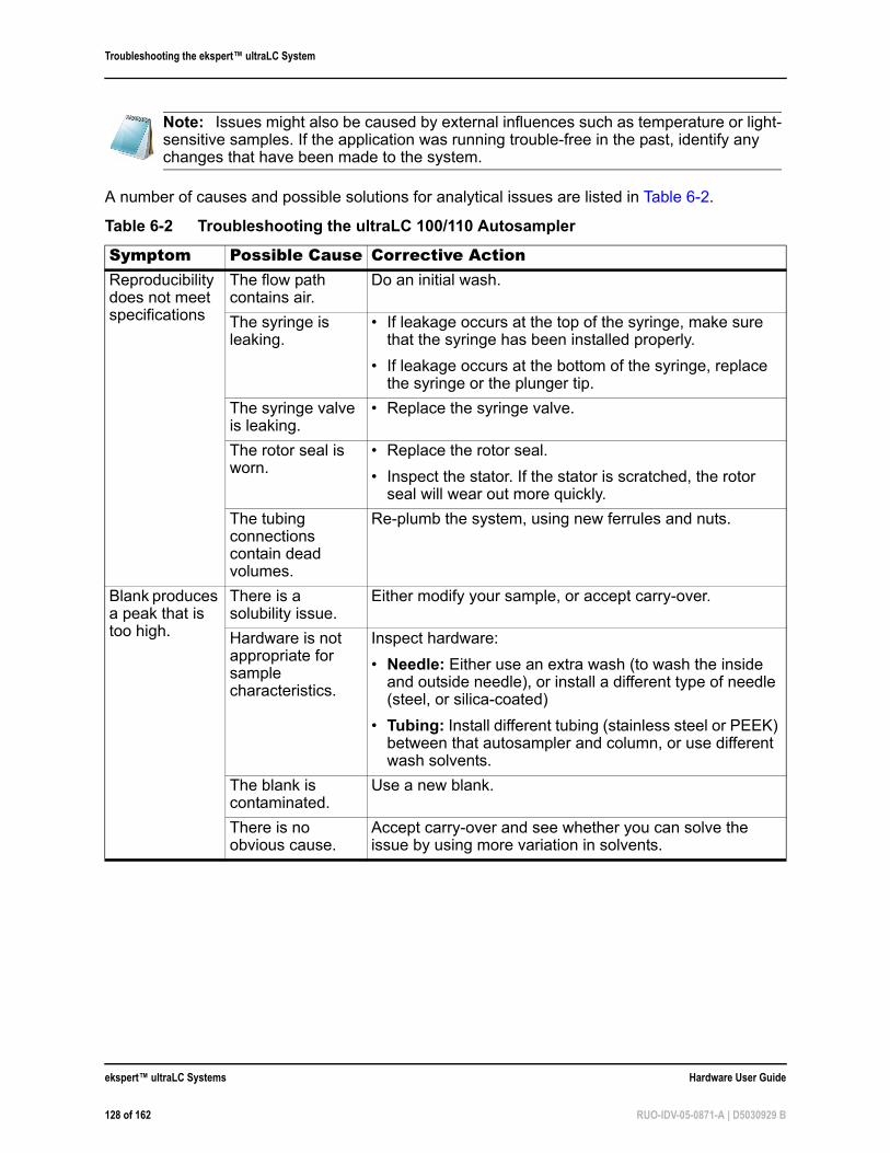
Troubleshooting the ekspert™ ultraLC System
A number of causes and possible solutions for analytical issues are listed in Table 6-2.
Note: Issues might also be caused by external influences such as temperature or light-sensitive samples. If the application was running trouble-free in the past, identify any changes that have been made to the system.
Table 6-2 Troubleshooting the ultraLC 100/110 Autosampler
Symptom Possible Cause Corrective ActionReproducibility does not meet specifications
The flow path contains air.
Do an initial wash.
The syringe is leaking.
• If leakage occurs at the top of the syringe, make sure that the syringe has been installed properly.
• If leakage occurs at the bottom of the syringe, replace the syringe or the plunger tip.
The syringe valve is leaking.
• Replace the syringe valve.
The rotor seal is worn.
• Replace the rotor seal.
• Inspect the stator. If the stator is scratched, the rotor seal will wear out more quickly.
The tubing connections contain dead volumes.
Re-plumb the system, using new ferrules and nuts.
Blank produces a peak that is too high.
There is a solubility issue.
Either modify your sample, or accept carry-over.
Hardware is not appropriate for sample characteristics.
Inspect hardware:
• Needle: Either use an extra wash (to wash the inside and outside needle), or install a different type of needle (steel, or silica-coated)
• Tubing: Install different tubing (stainless steel or PEEK) between that autosampler and column, or use different wash solvents.
The blank is contaminated.
Use a new blank.
There is no obvious cause.
Accept carry-over and see whether you can solve the issue by using more variation in solvents.
ekspert™ ultraLC Systems Hardware User Guide
128 of 162 RUO-IDV-05-0871-A | D5030929 B
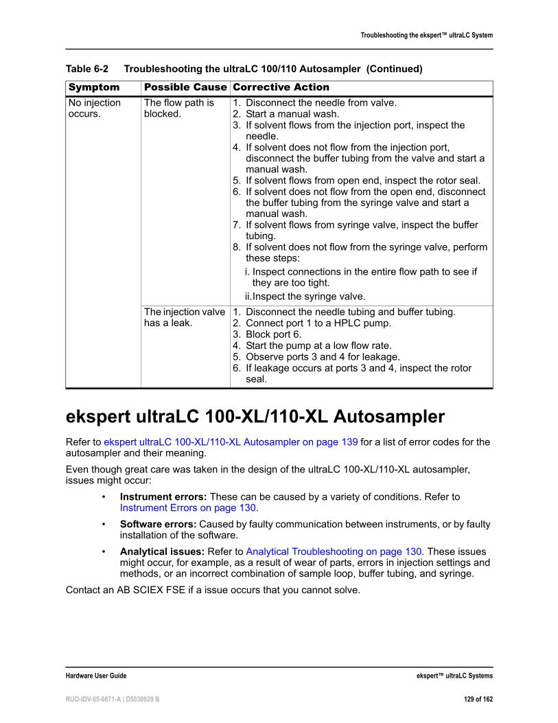
Troubleshooting the ekspert™ ultraLC System
ekspert ultraLC 100-XL/110-XL AutosamplerRefer to ekspert ultraLC 100-XL/110-XL Autosampler on page 139 for a list of error codes for the autosampler and their meaning.
Even though great care was taken in the design of the ultraLC 100-XL/110-XL autosampler, issues might occur:
• Instrument errors: These can be caused by a variety of conditions. Refer to Instrument Errors on page 130.
• Software errors: Caused by faulty communication between instruments, or by faulty installation of the software.
• Analytical issues: Refer to Analytical Troubleshooting on page 130. These issues might occur, for example, as a result of wear of parts, errors in injection settings and methods, or an incorrect combination of sample loop, buffer tubing, and syringe.
Contact an AB SCIEX FSE if a issue occurs that you cannot solve.
No injection occurs.
The flow path is blocked.
1. Disconnect the needle from valve.2. Start a manual wash.3. If solvent flows from the injection port, inspect the
needle.4. If solvent does not flow from the injection port,
disconnect the buffer tubing from the valve and start a manual wash.
5. If solvent flows from open end, inspect the rotor seal.6. If solvent does not flow from the open end, disconnect
the buffer tubing from the syringe valve and start a manual wash.
7. If solvent flows from syringe valve, inspect the buffer tubing.
8. If solvent does not flow from the syringe valve, perform these steps:
i. Inspect connections in the entire flow path to see if they are too tight.
ii.Inspect the syringe valve.
The injection valve has a leak.
1. Disconnect the needle tubing and buffer tubing.2. Connect port 1 to a HPLC pump.3. Block port 6.4. Start the pump at a low flow rate.5. Observe ports 3 and 4 for leakage. 6. If leakage occurs at ports 3 and 4, inspect the rotor
seal.
Table 6-2 Troubleshooting the ultraLC 100/110 Autosampler (Continued)
Symptom Possible Cause Corrective Action
Hardware User Guide ekspert™ ultraLC Systems
RUO-IDV-05-0871-A | D5030929 B 129 of 162
Troubleshooting the ekspert™ ultraLC System
Instrument ErrorsIncidental fault conditions might occur in any instrument. The ultraLC 100-XL/110-XL autosampler will generate an instrument error message with an error number, a short description of the error and instructions on how to proceed.
In most cases, you will be asked to initialize the system or turn the system off and then on again. Follow the instructions in the ekspert ultraLC software to resolve the error status.
Make sure that maintenance is performed regularly.
Check a Valve
To check a valve, remove the valve and check all parts for wear and dirt.
1. In the status bar, right-click the icon for the autosampler and then click expert 110-XL Autosampler > Direct Control.
2. In the Wash group, select System wash.
3. Click Start to start the wash.
4. Click Stop to end the wash.
Test System Functions
1. In the status bar, right-click the icon for the autosampler and then click expert 110-XL Autosampler > Direct Control.
2. Use this dialog to test the injection valve and other system functions.
Turn the System Off and On
1. Check that the communication cable between ultraLC 100-XL/110-XL autosampler and the computer is properly installed.
2. Turn the autosampler off with the switch at the back of the autosampler.
3. Turn the autosampler on again. The system is initialized and is now ready for use.
Analytical TroubleshootingAnalytical issues like bad reproducibility or carry-over might occur in any UHPLC system. The first thing to do is to determine whether the issue is caused by the autosampler or by the rest of the system:
• Replace the injection valve with a manual injection valve to check for valve issues and then do a number of full loop injections. If the results are fine, the fault is in the autosampler. If not, check the rest of the UHPLC system.
• Check for external influences, such as temperature and light-sensitive samples.
• Verify that the application was running trouble-free before and that no changes have been made to the system.
A number of causes and possible solutions for analytical issues are listed in Table 6-3.
WARNING! If the LED (top right corner of the instrument) is not lighted, a fuse might have blown.
ekspert™ ultraLC Systems Hardware User Guide
130 of 162 RUO-IDV-05-0871-A | D5030929 B
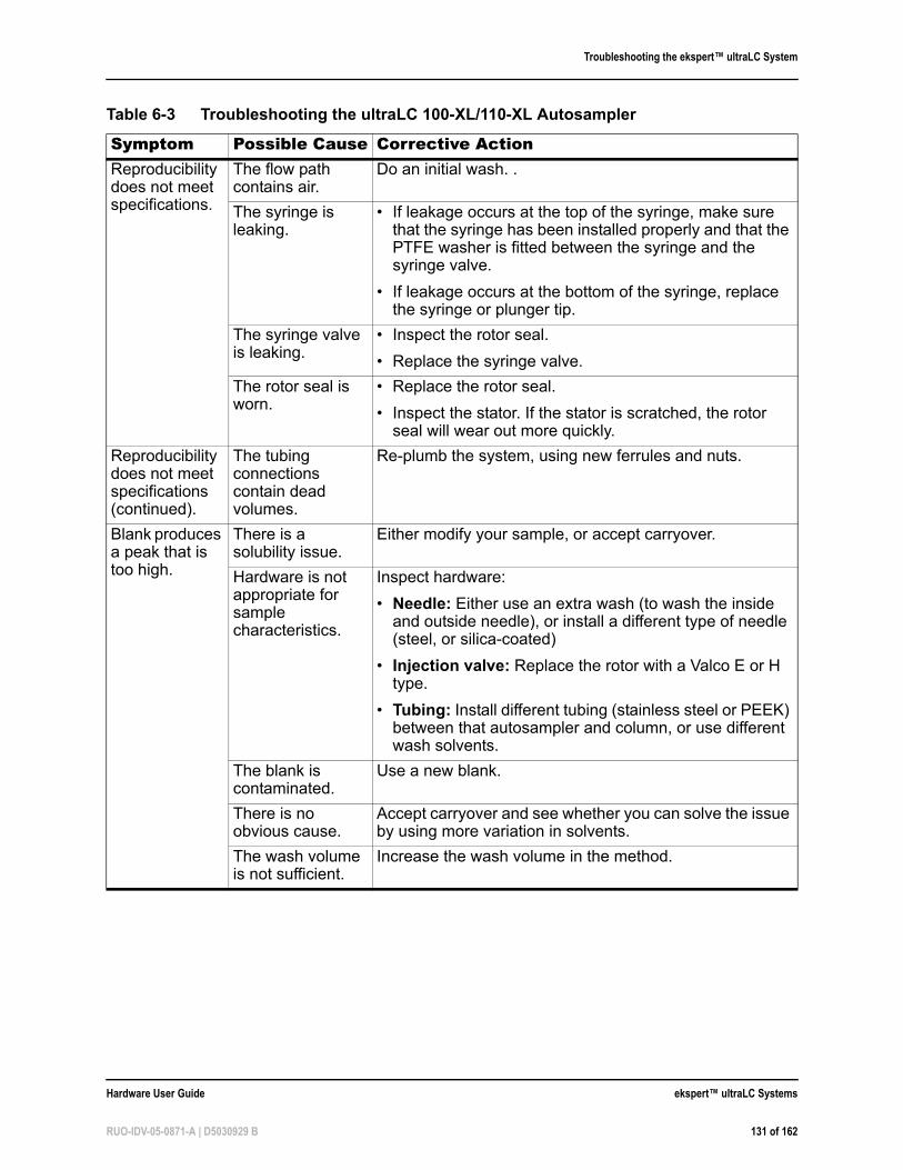
Troubleshooting the ekspert™ ultraLC System
Table 6-3 Troubleshooting the ultraLC 100-XL/110-XL Autosampler
Symptom Possible Cause Corrective ActionReproducibility does not meet specifications.
The flow path contains air.
Do an initial wash. .
The syringe is leaking.
• If leakage occurs at the top of the syringe, make sure that the syringe has been installed properly and that the PTFE washer is fitted between the syringe and the syringe valve.
• If leakage occurs at the bottom of the syringe, replace the syringe or plunger tip.
The syringe valve is leaking.
• Inspect the rotor seal.
• Replace the syringe valve.
The rotor seal is worn.
• Replace the rotor seal.
• Inspect the stator. If the stator is scratched, the rotor seal will wear out more quickly.
Reproducibility does not meet specifications (continued).
The tubing connections contain dead volumes.
Re-plumb the system, using new ferrules and nuts.
Blank produces a peak that is too high.
There is a solubility issue.
Either modify your sample, or accept carryover.
Hardware is not appropriate for sample characteristics.
Inspect hardware:
• Needle: Either use an extra wash (to wash the inside and outside needle), or install a different type of needle (steel, or silica-coated)
• Injection valve: Replace the rotor with a Valco E or H type.
• Tubing: Install different tubing (stainless steel or PEEK) between that autosampler and column, or use different wash solvents.
The blank is contaminated.
Use a new blank.
There is no obvious cause.
Accept carryover and see whether you can solve the issue by using more variation in solvents.
The wash volume is not sufficient.
Increase the wash volume in the method.
Hardware User Guide ekspert™ ultraLC Systems
RUO-IDV-05-0871-A | D5030929 B 131 of 162
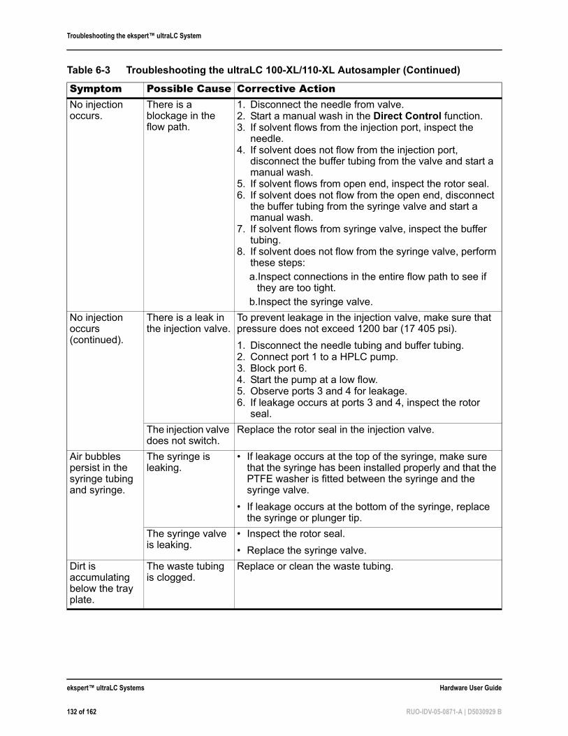
Troubleshooting the ekspert™ ultraLC System
No injection occurs.
There is a blockage in the flow path.
1. Disconnect the needle from valve.2. Start a manual wash in the Direct Control function.3. If solvent flows from the injection port, inspect the
needle.4. If solvent does not flow from the injection port,
disconnect the buffer tubing from the valve and start a manual wash.
5. If solvent flows from open end, inspect the rotor seal.6. If solvent does not flow from the open end, disconnect
the buffer tubing from the syringe valve and start a manual wash.
7. If solvent flows from syringe valve, inspect the buffer tubing.
8. If solvent does not flow from the syringe valve, perform these steps:
a.Inspect connections in the entire flow path to see if they are too tight.
b.Inspect the syringe valve.
No injection occurs (continued).
There is a leak in the injection valve.
To prevent leakage in the injection valve, make sure that pressure does not exceed 1200 bar (17 405 psi).
1. Disconnect the needle tubing and buffer tubing.2. Connect port 1 to a HPLC pump.3. Block port 6.4. Start the pump at a low flow.5. Observe ports 3 and 4 for leakage. 6. If leakage occurs at ports 3 and 4, inspect the rotor
seal.
The injection valve does not switch.
Replace the rotor seal in the injection valve.
Air bubbles persist in the syringe tubing and syringe.
The syringe is leaking.
• If leakage occurs at the top of the syringe, make sure that the syringe has been installed properly and that the PTFE washer is fitted between the syringe and the syringe valve.
• If leakage occurs at the bottom of the syringe, replace the syringe or plunger tip.
The syringe valve is leaking.
• Inspect the rotor seal.
• Replace the syringe valve.
Dirt is accumulating below the tray plate.
The waste tubing is clogged.
Replace or clean the waste tubing.
Table 6-3 Troubleshooting the ultraLC 100-XL/110-XL Autosampler (Continued)
Symptom Possible Cause Corrective Action
ekspert™ ultraLC Systems Hardware User Guide
132 of 162 RUO-IDV-05-0871-A | D5030929 B

Troubleshooting the ekspert™ ultraLC System
Contact an AB SCIEX FSE if you cannot solve the issue.
ekspert ultraLC 100/110 Column OvenRefer to ekspert ultraLC 100/110 Column Oven on page 140 for a list of error codes for the column oven and their meaning.
Warnings, Alarms, and Error Codes on the Front PanelWarnings, alarms, and error codes might appear on the front panel display. Turn the column oven off and on to clear an error, warning or alarm.
Liquid is accumulating at the front of the autosampler, on the foam under the sample tray and tray drive.
The autosampler is not sloped at the correct angle.
Adjust the autosampler position to increase the downward slope to the waste port and outlet.
Liquid is overflowing on to the bench.
Waste tubing or condensation tubing is clogged.
Clean the waste or condensation tubing.
Table 6-4 Troubleshooting the ultraLC 100/110 Column Oven
Symptom Possible Cause Corrective ActionTemperature ramps slowly
The voltage selector cartridge is installed incorrectly
Remove, invert, and install the voltage selector cartridge. For detailed instructions, refer to the Installation Guide for your system.
Table 6-5 Column Oven Alarms
Alarm ExplanationVapor Alarm 1 When a vapor alarm is detected, the column oven responds with the
following actions:
1. The alarm buzzer sounds.2. The vapor alarm message is shown.3. The alarm relay activates.4. The temperature control turns off.5. The temperature program stops.
To reset the alarm and return to the temperature menu, press a key on the column oven. The vapor sensor is disabled for two minutes to allow you to solve the vapor issue. You can then start the program again.
Table 6-3 Troubleshooting the ultraLC 100-XL/110-XL Autosampler (Continued)
Symptom Possible Cause Corrective Action
Hardware User Guide ekspert™ ultraLC Systems
RUO-IDV-05-0871-A | D5030929 B 133 of 162
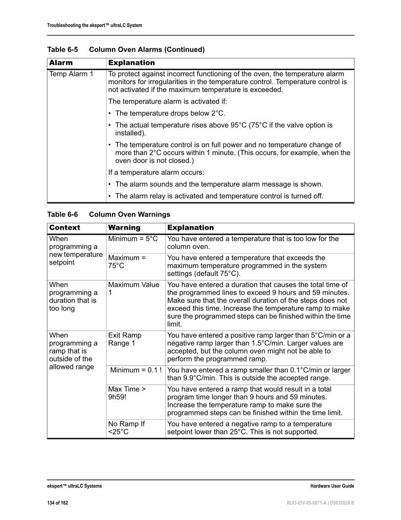
Troubleshooting the ekspert™ ultraLC System
Temp Alarm 1 To protect against incorrect functioning of the oven, the temperature alarm monitors for irregularities in the temperature control. Temperature control is not activated if the maximum temperature is exceeded.
The temperature alarm is activated if:
• The temperature drops below 2°C.
• The actual temperature rises above 95°C (75°C if the valve option is installed).
• The temperature control is on full power and no temperature change of more than 2°C occurs within 1 minute. (This occurs, for example, when the oven door is not closed.)
If a temperature alarm occurs:
• The alarm sounds and the temperature alarm message is shown.
• The alarm relay is activated and temperature control is turned off.
Table 6-6 Column Oven Warnings
Context Warning ExplanationWhen programming a new temperature setpoint
Minimum = 5°C You have entered a temperature that is too low for the column oven.
Maximum = 75°C
You have entered a temperature that exceeds the maximum temperature programmed in the system settings (default 75°C).
When programming a duration that is too long
Maximum Value 1
You have entered a duration that causes the total time of the programmed lines to exceed 9 hours and 59 minutes. Make sure that the overall duration of the steps does not exceed this time. Increase the temperature ramp to make sure the programmed steps can be finished within the time limit.
When programming a ramp that is outside of the allowed range
Exit Ramp Range 1
You have entered a positive ramp larger than 5°C/min or a negative ramp larger than 1.5°C/min. Larger values are accepted, but the column oven might not be able to perform the programmed ramp.
Minimum = 0.1 ! You have entered a ramp smaller than 0.1°C/min or larger than 9.9°C/min. This is outside the accepted range.
Max Time > 9h59!
You have entered a ramp that would result in a total program time longer than 9 hours and 59 minutes. Increase the temperature ramp to make sure the programmed steps can be finished within the time limit.
No Ramp If <25°C
You have entered a negative ramp to a temperature setpoint lower than 25°C. This is not supported.
Table 6-5 Column Oven Alarms (Continued)
Alarm Explanation
ekspert™ ultraLC Systems Hardware User Guide
134 of 162 RUO-IDV-05-0871-A | D5030929 B
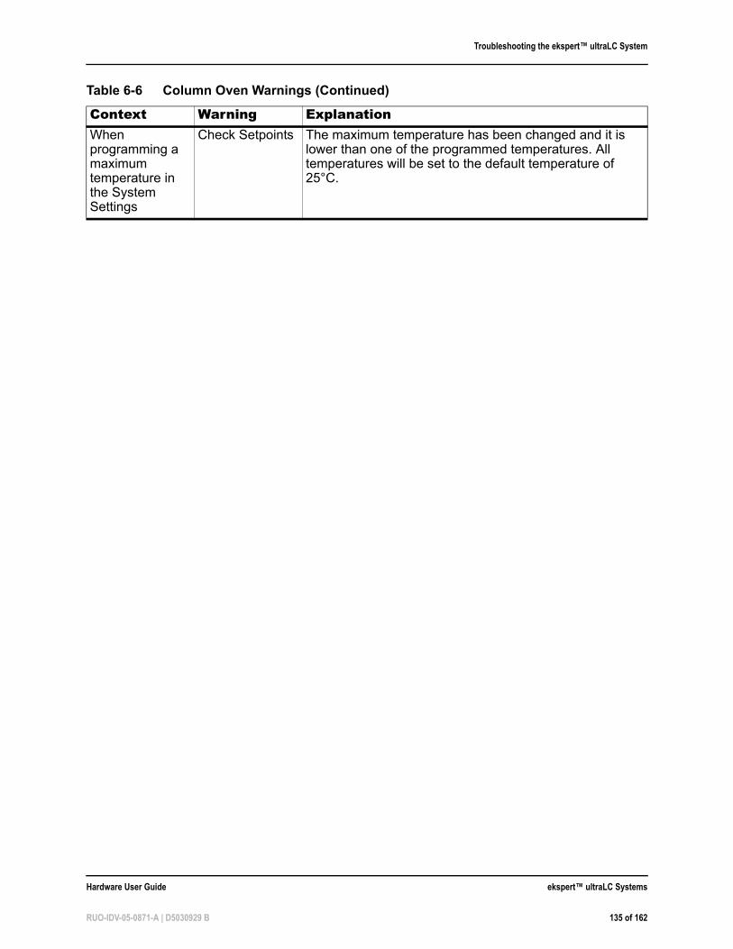
Troubleshooting the ekspert™ ultraLC System
When programming a maximum temperature in the System Settings
Check Setpoints The maximum temperature has been changed and it is lower than one of the programmed temperatures. All temperatures will be set to the default temperature of 25°C.
Table 6-6 Column Oven Warnings (Continued)
Context Warning Explanation
Hardware User Guide ekspert™ ultraLC Systems
RUO-IDV-05-0871-A | D5030929 B 135 of 162
Troubleshooting the ekspert™ ultraLC System
ekspert™ ultraLC Systems Hardware User Guide
136 of 162 RUO-IDV-05-0871-A | D5030929 B
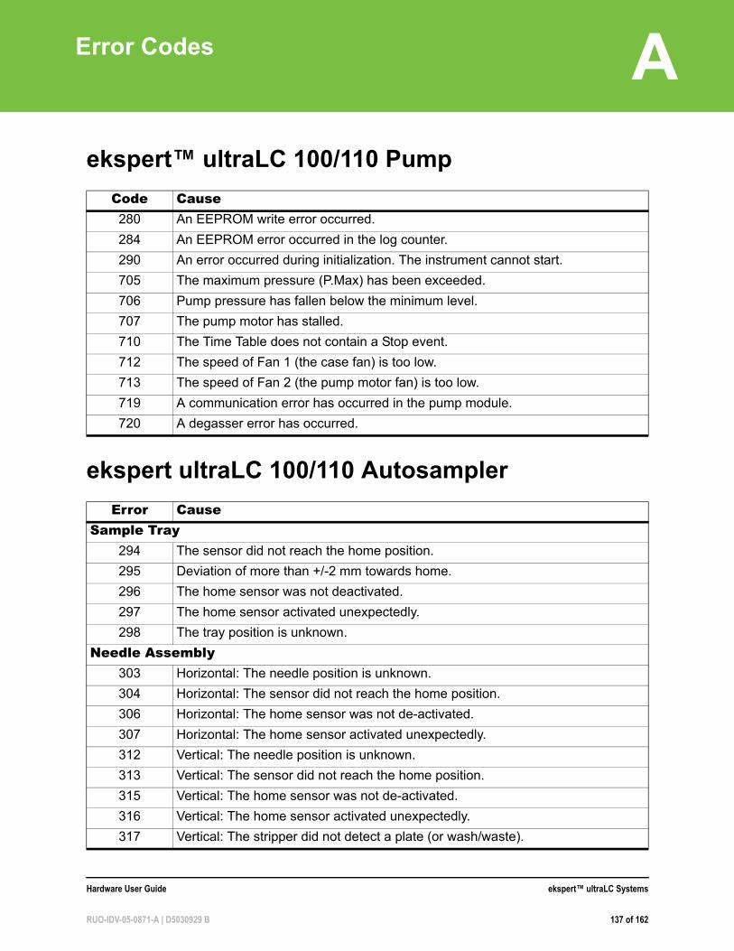
A
Error Codesekspert™ ultraLC 100/110 Pump
ekspert ultraLC 100/110 Autosampler
Code Cause280 An EEPROM write error occurred.
284 An EEPROM error occurred in the log counter.
290 An error occurred during initialization. The instrument cannot start.
705 The maximum pressure (P.Max) has been exceeded.
706 Pump pressure has fallen below the minimum level.
707 The pump motor has stalled.
710 The Time Table does not contain a Stop event.
712 The speed of Fan 1 (the case fan) is too low.
713 The speed of Fan 2 (the pump motor fan) is too low.
719 A communication error has occurred in the pump module.
720 A degasser error has occurred.
Error CauseSample Tray
294 The sensor did not reach the home position.
295 Deviation of more than +/-2 mm towards home.
296 The home sensor was not deactivated.
297 The home sensor activated unexpectedly.
298 The tray position is unknown.
Needle Assembly303 Horizontal: The needle position is unknown.
304 Horizontal: The sensor did not reach the home position.
306 Horizontal: The home sensor was not de-activated.
307 Horizontal: The home sensor activated unexpectedly.
312 Vertical: The needle position is unknown.
313 Vertical: The sensor did not reach the home position.
315 Vertical: The home sensor was not de-activated.
316 Vertical: The home sensor activated unexpectedly.
317 Vertical: The stripper did not detect a plate (or wash/waste).
Hardware User Guide ekspert™ ultraLC Systems
RUO-IDV-05-0871-A | D5030929 B 137 of 162
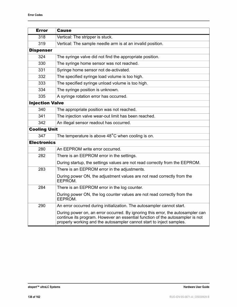
Error Codes
318 Vertical: The stripper is stuck.
319 Vertical: The sample needle arm is at an invalid position.
Dispenser324 The syringe valve did not find the appropriate position.
330 The syringe home sensor was not reached.
331 Syringe home sensor not de-activated.
332 The specified syringe load volume is too high.
333 The specified syringe unload volume is too high.
334 The syringe position is unknown.
335 A syringe rotation error has occurred.
Injection Valve340 The appropriate position was not reached.
341 The injection valve wear-out limit has been reached.
342 An illegal sensor readout has occurred.
Cooling Unit347 The temperature is above 48°C when cooling is on.
Electronics280 An EEPROM write error occurred.
282 There is an EEPROM error in the settings.
During startup, the settings values are not read correctly from the EEPROM.
283 There is an EEPROM error in the adjustments.
During power ON, the adjustment values are not read correctly from the EEPROM.
284 There is an EEPROM error in the log counter.
During power ON, the log counter values are not read correctly from the EEPROM.
290 An error occurred during initialization. The autosampler cannot start.
During power on, an error occurred. By ignoring this error, the autosampler can continue its program. However an essential function of the autosampler is not properly working and the autosampler cannot start to inject samples.
Error Cause
ekspert™ ultraLC Systems Hardware User Guide
138 of 162 RUO-IDV-05-0871-A | D5030929 B
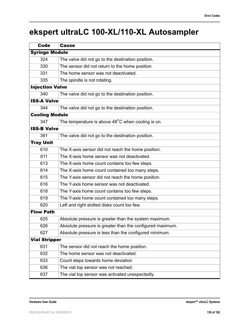
Error Codes
ekspert ultraLC 100-XL/110-XL Autosampler
Code CauseSyringe Module
324 The valve did not go to the destination position.
330 The sensor did not return to the home position.
331 The home sensor was not deactivated.
335 The spindle is not rotating.
Injection Valve340 The valve did not go to the destination position.
ISS-A Valve344 The valve did not go to the destination position.
Cooling Module347 The temperature is above 48°C when cooling is on.
ISS-B Valve391 The valve did not go to the destination position.
Tray Unit610 The X-axis sensor did not reach the home position.
611 The X-axis home sensor was not deactivated
613 The X-axis home count contains too few steps.
614 The X-axis home count contained too many steps.
615 The Y-axis sensor did not reach the home position.
616 The Y-axis home sensor was not deactivated.
618 The Y-axis home count contains too few steps.
619 The Y-axis home count contained too many steps.
620 Left and right slotted disks count too few.
Flow Path625 Absolute pressure is greater than the system maximum.
626 Absolute pressure is greater than the configured maximum.
627 Absolute pressure is less than the configured minimum.
Vial Stripper631 The sensor did not reach the home position.
632 The home sensor was not deactivated.
633 Count steps towards home deviation
636 The vial top sensor was not reached.
637 The vial top sensor was activated unexpectedly.
Hardware User Guide ekspert™ ultraLC Systems
RUO-IDV-05-0871-A | D5030929 B 139 of 162
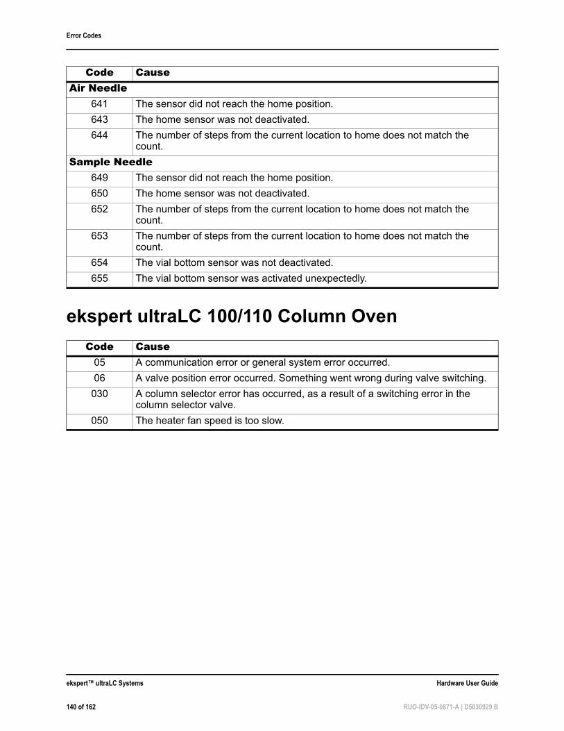
Error Codes
ekspert ultraLC 100/110 Column Oven
Air Needle641 The sensor did not reach the home position.
643 The home sensor was not deactivated.
644 The number of steps from the current location to home does not match the count.
Sample Needle649 The sensor did not reach the home position.
650 The home sensor was not deactivated.
652 The number of steps from the current location to home does not match the count.
653 The number of steps from the current location to home does not match the count.
654 The vial bottom sensor was not deactivated.
655 The vial bottom sensor was activated unexpectedly.
Code Cause05 A communication error or general system error occurred.
06 A valve position error occurred. Something went wrong during valve switching.
030 A column selector error has occurred, as a result of a switching error in the column selector valve.
050 The heater fan speed is too slow.
Code Cause
ekspert™ ultraLC Systems Hardware User Guide
140 of 162 RUO-IDV-05-0871-A | D5030929 B
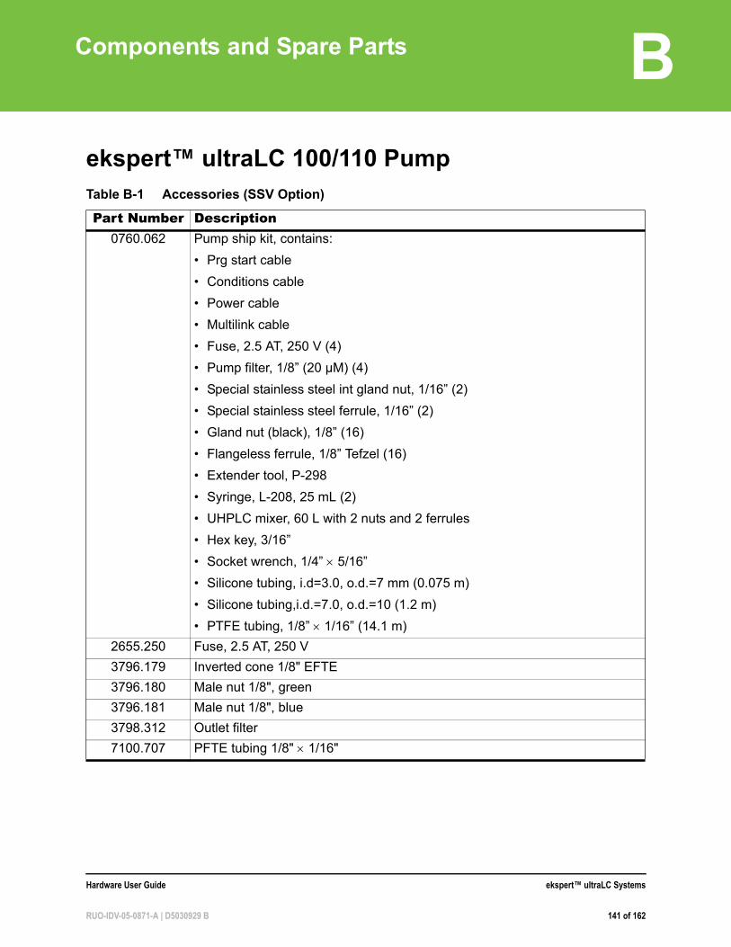
B
Components and Spare Partsekspert™ ultraLC 100/110 PumpTable B-1 Accessories (SSV Option)
Part Number Description0760.062 Pump ship kit, contains:
• Prg start cable
• Conditions cable
• Power cable
• Multilink cable
• Fuse, 2.5 AT, 250 V (4)
• Pump filter, 1/8” (20 µM) (4)
• Special stainless steel int gland nut, 1/16” (2)
• Special stainless steel ferrule, 1/16” (2)
• Gland nut (black), 1/8” (16)
• Flangeless ferrule, 1/8” Tefzel (16)
• Extender tool, P-298
• Syringe, L-208, 25 mL (2)
• UHPLC mixer, 60 L with 2 nuts and 2 ferrules
• Hex key, 3/16”
• Socket wrench, 1/4” 5/16”
• Silicone tubing, i.d=3.0, o.d.=7 mm (0.075 m)
• Silicone tubing,i.d.=7.0, o.d.=10 (1.2 m)
• PTFE tubing, 1/8” 1/16” (14.1 m)
2655.250 Fuse, 2.5 AT, 250 V
3796.179 Inverted cone 1/8" EFTE
3796.180 Male nut 1/8", green
3796.181 Male nut 1/8", blue
3798.312 Outlet filter
7100.707 PFTE tubing 1/8" 1/16"
Hardware User Guide ekspert™ ultraLC Systems
RUO-IDV-05-0871-A | D5030929 B 141 of 162
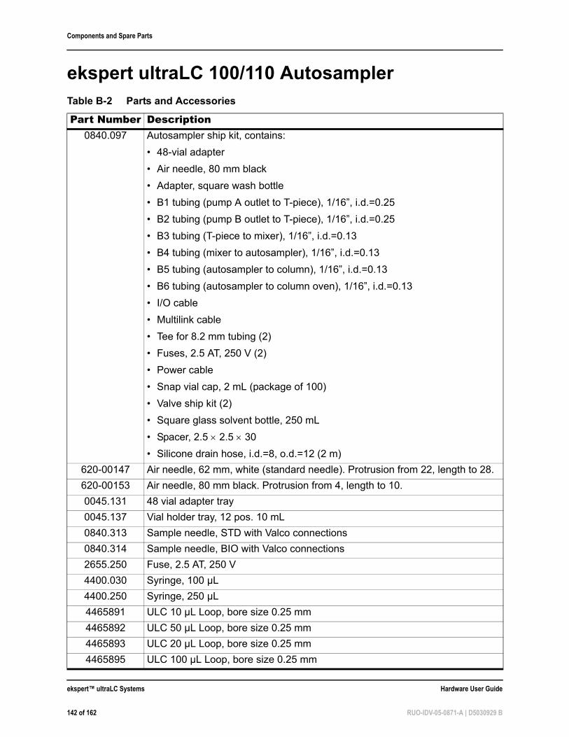
Components and Spare Parts
ekspert ultraLC 100/110 AutosamplerTable B-2 Parts and Accessories
Part Number Description0840.097 Autosampler ship kit, contains:
• 48-vial adapter
• Air needle, 80 mm black
• Adapter, square wash bottle
• B1 tubing (pump A outlet to T-piece), 1/16”, i.d.=0.25
• B2 tubing (pump B outlet to T-piece), 1/16”, i.d.=0.25
• B3 tubing (T-piece to mixer), 1/16”, i.d.=0.13
• B4 tubing (mixer to autosampler), 1/16”, i.d.=0.13
• B5 tubing (autosampler to column), 1/16”, i.d.=0.13
• B6 tubing (autosampler to column oven), 1/16”, i.d.=0.13
• I/O cable
• Multilink cable
• Tee for 8.2 mm tubing (2)
• Fuses, 2.5 AT, 250 V (2)
• Power cable
• Snap vial cap, 2 mL (package of 100)
• Valve ship kit (2)
• Square glass solvent bottle, 250 mL
• Spacer, 2.5 2.5 30
• Silicone drain hose, i.d.=8, o.d.=12 (2 m)
620-00147 Air needle, 62 mm, white (standard needle). Protrusion from 22, length to 28.
620-00153 Air needle, 80 mm black. Protrusion from 4, length to 10.
0045.131 48 vial adapter tray
0045.137 Vial holder tray, 12 pos. 10 mL
0840.313 Sample needle, STD with Valco connections
0840.314 Sample needle, BIO with Valco connections
2655.250 Fuse, 2.5 AT, 250 V
4400.030 Syringe, 100 µL
4400.250 Syringe, 250 µL
4465891 ULC 10 µL Loop, bore size 0.25 mm
4465892 ULC 50 µL Loop, bore size 0.25 mm
4465893 ULC 20 µL Loop, bore size 0.25 mm
4465895 ULC 100 µL Loop, bore size 0.25 mm
ekspert™ ultraLC Systems Hardware User Guide
142 of 162 RUO-IDV-05-0871-A | D5030929 B
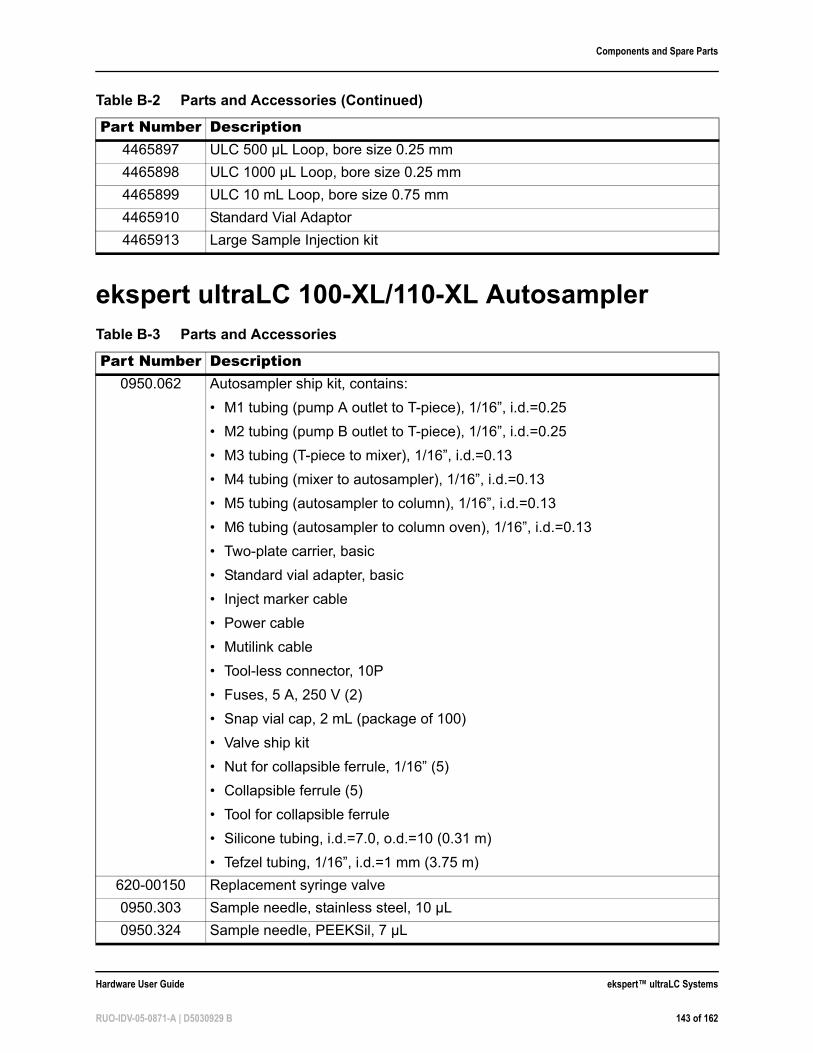
Components and Spare Parts
ekspert ultraLC 100-XL/110-XL Autosampler
4465897 ULC 500 µL Loop, bore size 0.25 mm
4465898 ULC 1000 µL Loop, bore size 0.25 mm
4465899 ULC 10 mL Loop, bore size 0.75 mm
4465910 Standard Vial Adaptor
4465913 Large Sample Injection kit
Table B-3 Parts and Accessories
Part Number Description0950.062 Autosampler ship kit, contains:
• M1 tubing (pump A outlet to T-piece), 1/16”, i.d.=0.25
• M2 tubing (pump B outlet to T-piece), 1/16”, i.d.=0.25
• M3 tubing (T-piece to mixer), 1/16”, i.d.=0.13
• M4 tubing (mixer to autosampler), 1/16”, i.d.=0.13
• M5 tubing (autosampler to column), 1/16”, i.d.=0.13
• M6 tubing (autosampler to column oven), 1/16”, i.d.=0.13
• Two-plate carrier, basic
• Standard vial adapter, basic
• Inject marker cable
• Power cable
• Mutilink cable
• Tool-less connector, 10P
• Fuses, 5 A, 250 V (2)
• Snap vial cap, 2 mL (package of 100)
• Valve ship kit
• Nut for collapsible ferrule, 1/16” (5)
• Collapsible ferrule (5)
• Tool for collapsible ferrule
• Silicone tubing, i.d.=7.0, o.d.=10 (0.31 m)
• Tefzel tubing, 1/16”, i.d.=1 mm (3.75 m)
620-00150 Replacement syringe valve
0950.303 Sample needle, stainless steel, 10 µL
0950.324 Sample needle, PEEKSil, 7 µL
Table B-2 Parts and Accessories (Continued)
Part Number Description
Hardware User Guide ekspert™ ultraLC Systems
RUO-IDV-05-0871-A | D5030929 B 143 of 162
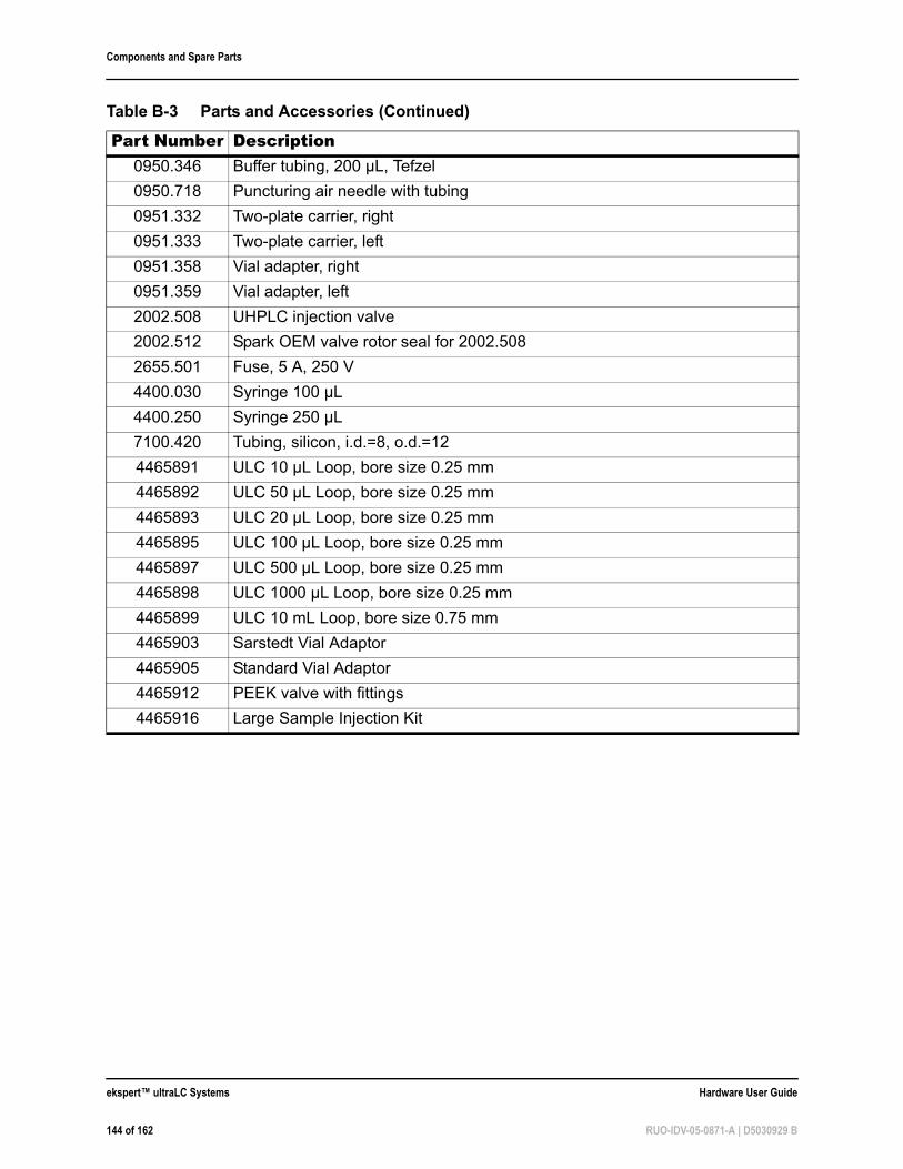
Components and Spare Parts
0950.346 Buffer tubing, 200 µL, Tefzel
0950.718 Puncturing air needle with tubing
0951.332 Two-plate carrier, right
0951.333 Two-plate carrier, left
0951.358 Vial adapter, right
0951.359 Vial adapter, left
2002.508 UHPLC injection valve
2002.512 Spark OEM valve rotor seal for 2002.508
2655.501 Fuse, 5 A, 250 V
4400.030 Syringe 100 µL
4400.250 Syringe 250 µL
7100.420 Tubing, silicon, i.d.=8, o.d.=12
4465891 ULC 10 µL Loop, bore size 0.25 mm
4465892 ULC 50 µL Loop, bore size 0.25 mm
4465893 ULC 20 µL Loop, bore size 0.25 mm
4465895 ULC 100 µL Loop, bore size 0.25 mm
4465897 ULC 500 µL Loop, bore size 0.25 mm
4465898 ULC 1000 µL Loop, bore size 0.25 mm
4465899 ULC 10 mL Loop, bore size 0.75 mm
4465903 Sarstedt Vial Adaptor
4465905 Standard Vial Adaptor
4465912 PEEK valve with fittings
4465916 Large Sample Injection Kit
Table B-3 Parts and Accessories (Continued)
Part Number Description
ekspert™ ultraLC Systems Hardware User Guide
144 of 162 RUO-IDV-05-0871-A | D5030929 B
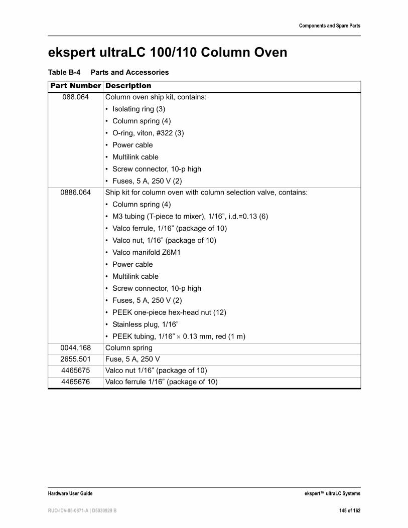
Components and Spare Parts
ekspert ultraLC 100/110 Column OvenTable B-4 Parts and Accessories
Part Number Description088.064 Column oven ship kit, contains:
• Isolating ring (3)
• Column spring (4)
• O-ring, viton, #322 (3)
• Power cable
• Multilink cable
• Screw connector, 10-p high
• Fuses, 5 A, 250 V (2)
0886.064 Ship kit for column oven with column selection valve, contains:
• Column spring (4)
• M3 tubing (T-piece to mixer), 1/16”, i.d.=0.13 (6)
• Valco ferrule, 1/16” (package of 10)
• Valco nut, 1/16” (package of 10)
• Valco manifold Z6M1
• Power cable
• Multilink cable
• Screw connector, 10-p high
• Fuses, 5 A, 250 V (2)
• PEEK one-piece hex-head nut (12)
• Stainless plug, 1/16”
• PEEK tubing, 1/16” 0.13 mm, red (1 m)
0044.168 Column spring
2655.501 Fuse, 5 A, 250 V
4465675 Valco nut 1/16” (package of 10)
4465676 Valco ferrule 1/16” (package of 10)
Hardware User Guide ekspert™ ultraLC Systems
RUO-IDV-05-0871-A | D5030929 B 145 of 162

Components and Spare Parts
ekspert™ ultraLC Systems Hardware User Guide
146 of 162 RUO-IDV-05-0871-A | D5030929 B
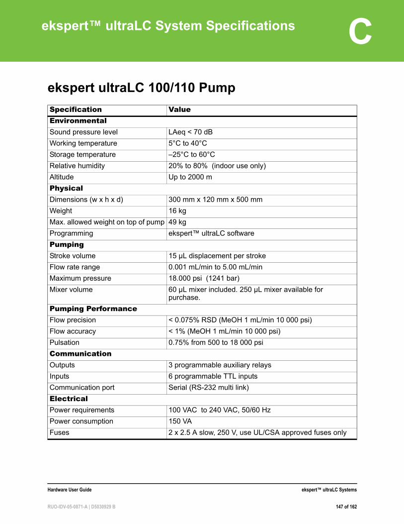
C
ekspert™ ultraLC System Specificationsekspert ultraLC 100/110 Pump
Specification ValueEnvironmentalSound pressure level LAeq < 70 dB
Working temperature 5°C to 40°C
Storage temperature –25°C to 60°C
Relative humidity 20% to 80% (indoor use only)
Altitude Up to 2000 m
PhysicalDimensions (w x h x d) 300 mm x 120 mm x 500 mm
Weight 16 kg
Max. allowed weight on top of pump 49 kg
Programming ekspert™ ultraLC software
PumpingStroke volume 15 µL displacement per stroke
Flow rate range 0.001 mL/min to 5.00 mL/min
Maximum pressure 18.000 psi (1241 bar)
Mixer volume 60 µL mixer included. 250 µL mixer available for purchase.
Pumping PerformanceFlow precision < 0.075% RSD (MeOH 1 mL/min 10 000 psi)
Flow accuracy < 1% (MeOH 1 mL/min 10 000 psi)
Pulsation 0.75% from 500 to 18 000 psi
CommunicationOutputs 3 programmable auxiliary relays
Inputs 6 programmable TTL inputs
Communication port Serial (RS-232 multi link)
ElectricalPower requirements 100 VAC to 240 VAC, 50/60 Hz
Power consumption 150 VA
Fuses 2 x 2.5 A slow, 250 V, use UL/CSA approved fuses only
Hardware User Guide ekspert™ ultraLC Systems
RUO-IDV-05-0871-A | D5030929 B 147 of 162
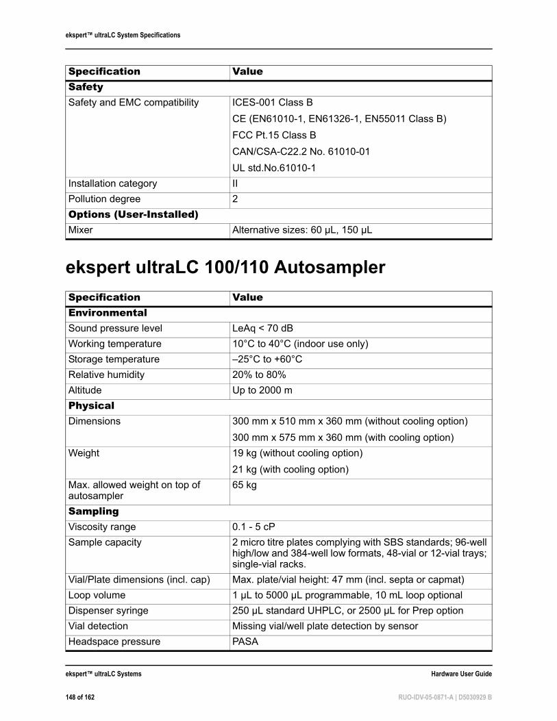
ekspert™ ultraLC System Specifications
ekspert ultraLC 100/110 Autosampler
SafetySafety and EMC compatibility ICES-001 Class B
CE (EN61010-1, EN61326-1, EN55011 Class B)
FCC Pt.15 Class B
CAN/CSA-C22.2 No. 61010-01
UL std.No.61010-1
Installation category II
Pollution degree 2
Options (User-Installed)Mixer Alternative sizes: 60 µL, 150 µL
Specification ValueEnvironmentalSound pressure level LeAq < 70 dB
Working temperature 10°C to 40°C (indoor use only)
Storage temperature –25°C to +60°C
Relative humidity 20% to 80%
Altitude Up to 2000 m
PhysicalDimensions 300 mm x 510 mm x 360 mm (without cooling option)
300 mm x 575 mm x 360 mm (with cooling option)
Weight 19 kg (without cooling option)
21 kg (with cooling option)
Max. allowed weight on top of autosampler
65 kg
SamplingViscosity range 0.1 - 5 cP
Sample capacity 2 micro titre plates complying with SBS standards; 96-well high/low and 384-well low formats, 48-vial or 12-vial trays; single-vial racks.
Vial/Plate dimensions (incl. cap) Max. plate/vial height: 47 mm (incl. septa or capmat)
Loop volume 1 µL to 5000 µL programmable, 10 mL loop optional
Dispenser syringe 250 µL standard UHPLC, or 2500 µL for Prep option
Vial detection Missing vial/well plate detection by sensor
Headspace pressure PASA
Specification Value
ekspert™ ultraLC Systems Hardware User Guide
148 of 162 RUO-IDV-05-0871-A | D5030929 B
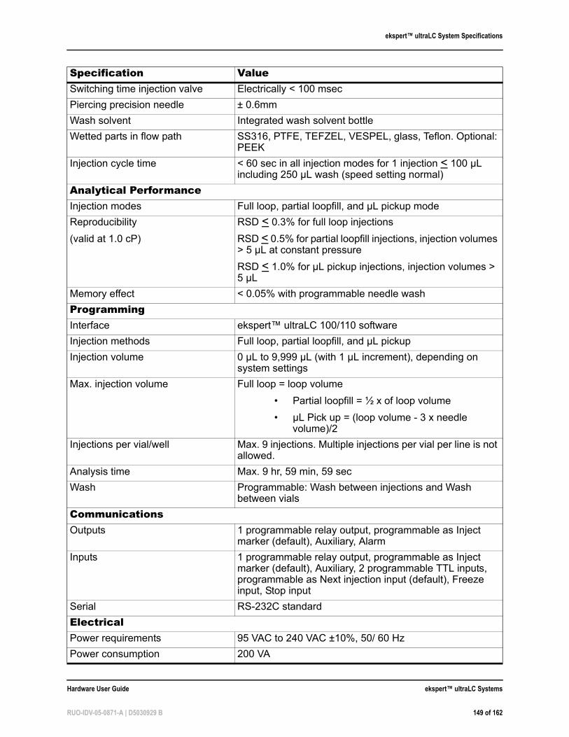
ekspert™ ultraLC System Specifications
Switching time injection valve Electrically < 100 msec
Piercing precision needle ± 0.6mm
Wash solvent Integrated wash solvent bottle
Wetted parts in flow path SS316, PTFE, TEFZEL, VESPEL, glass, Teflon. Optional: PEEK
Injection cycle time < 60 sec in all injection modes for 1 injection < 100 µL including 250 µL wash (speed setting normal)
Analytical PerformanceInjection modes Full loop, partial loopfill, and µL pickup mode
Reproducibility
(valid at 1.0 cP)
RSD < 0.3% for full loop injections
RSD < 0.5% for partial loopfill injections, injection volumes > 5 µL at constant pressure
RSD < 1.0% for µL pickup injections, injection volumes > 5 µL
Memory effect < 0.05% with programmable needle wash
ProgrammingInterface ekspert™ ultraLC 100/110 software
Injection methods Full loop, partial loopfill, and µL pickup
Injection volume 0 µL to 9,999 µL (with 1 µL increment), depending on system settings
Max. injection volume Full loop = loop volume
• Partial loopfill = ½ x of loop volume
• µL Pick up = (loop volume - 3 x needle volume)/2
Injections per vial/well Max. 9 injections. Multiple injections per vial per line is not allowed.
Analysis time Max. 9 hr, 59 min, 59 sec
Wash Programmable: Wash between injections and Wash between vials
CommunicationsOutputs 1 programmable relay output, programmable as Inject
marker (default), Auxiliary, Alarm
Inputs 1 programmable relay output, programmable as Inject marker (default), Auxiliary, 2 programmable TTL inputs, programmable as Next injection input (default), Freeze input, Stop input
Serial RS-232C standard
ElectricalPower requirements 95 VAC to 240 VAC ±10%, 50/ 60 Hz
Power consumption 200 VA
Specification Value
Hardware User Guide ekspert™ ultraLC Systems
RUO-IDV-05-0871-A | D5030929 B 149 of 162
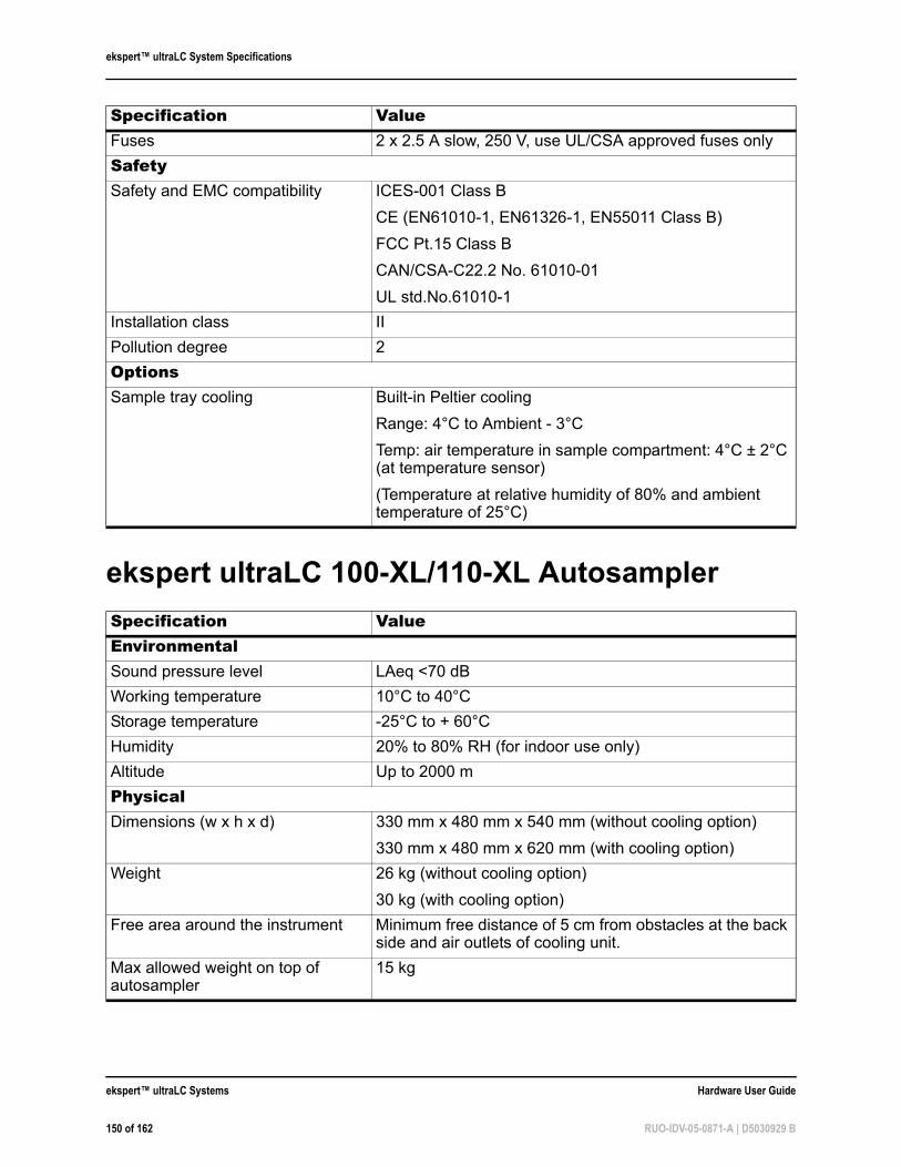
ekspert™ ultraLC System Specifications
ekspert ultraLC 100-XL/110-XL Autosampler
Fuses 2 x 2.5 A slow, 250 V, use UL/CSA approved fuses only
SafetySafety and EMC compatibility ICES-001 Class B
CE (EN61010-1, EN61326-1, EN55011 Class B)
FCC Pt.15 Class B
CAN/CSA-C22.2 No. 61010-01
UL std.No.61010-1
Installation class II
Pollution degree 2
OptionsSample tray cooling Built-in Peltier cooling
Range: 4°C to Ambient - 3°C
Temp: air temperature in sample compartment: 4°C ± 2°C (at temperature sensor)
(Temperature at relative humidity of 80% and ambient temperature of 25°C)
Specification ValueEnvironmentalSound pressure level LAeq <70 dB
Working temperature 10°C to 40°C
Storage temperature -25°C to + 60°C
Humidity 20% to 80% RH (for indoor use only)
Altitude Up to 2000 m
PhysicalDimensions (w x h x d) 330 mm x 480 mm x 540 mm (without cooling option)
330 mm x 480 mm x 620 mm (with cooling option)
Weight 26 kg (without cooling option)
30 kg (with cooling option)
Free area around the instrument Minimum free distance of 5 cm from obstacles at the back side and air outlets of cooling unit.
Max allowed weight on top of autosampler
15 kg
Specification Value
ekspert™ ultraLC Systems Hardware User Guide
150 of 162 RUO-IDV-05-0871-A | D5030929 B
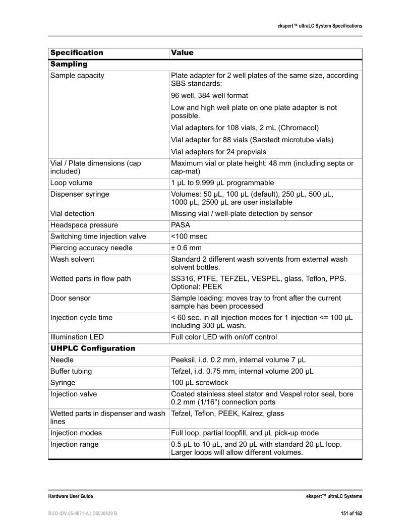
ekspert™ ultraLC System Specifications
SamplingSample capacity Plate adapter for 2 well plates of the same size, according
SBS standards:
96 well, 384 well format
Low and high well plate on one plate adapter is not possible.
Vial adapters for 108 vials, 2 mL (Chromacol)
Vial adapter for 88 vials (Sarstedt microtube vials)
Vial adapters for 24 prepvials
Vial / Plate dimensions (cap included)
Maximum vial or plate height: 48 mm (including septa or cap-mat)
Loop volume 1 µL to 9,999 µL programmable
Dispenser syringe Volumes: 50 µL, 100 µL (default), 250 µL, 500 µL, 1000 µL, 2500 µL are user installable
Vial detection Missing vial / well-plate detection by sensor
Headspace pressure PASA
Switching time injection valve <100 msec
Piercing accuracy needle ± 0.6 mm
Wash solvent Standard 2 different wash solvents from external wash solvent bottles.
Wetted parts in flow path SS316, PTFE, TEFZEL, VESPEL, glass, Teflon, PPS. Optional: PEEK
Door sensor Sample loading: moves tray to front after the current sample has been processed
Injection cycle time < 60 sec. in all injection modes for 1 injection <= 100 µL including 300 µL wash.
Illumination LED Full color LED with on/off control
UHPLC ConfigurationNeedle Peeksil, i.d. 0.2 mm, internal volume 7 µL
Buffer tubing Tefzel, i.d. 0.75 mm, internal volume 200 µL
Syringe 100 µL screwlock
Injection valve Coated stainless steel stator and Vespel rotor seal, bore 0.2 mm (1/16") connection ports
Wetted parts in dispenser and wash lines
Tefzel, Teflon, PEEK, Kalrez, glass
Injection modes Full loop, partial loopfill, and µL pick-up mode
Injection range 0.5 µL to 10 µL, and 20 µL with standard 20 µL loop. Larger loops will allow different volumes.
Specification Value
Hardware User Guide ekspert™ ultraLC Systems
RUO-IDV-05-0871-A | D5030929 B 151 of 162
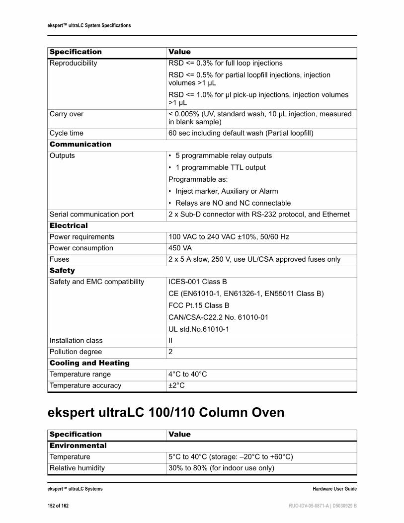
ekspert™ ultraLC System Specifications
ekspert ultraLC 100/110 Column Oven
Reproducibility RSD <= 0.3% for full loop injections
RSD <= 0.5% for partial loopfill injections, injection volumes >1 µL
RSD <= 1.0% for µl pick-up injections, injection volumes >1 µL
Carry over < 0.005% (UV, standard wash, 10 µL injection, measured in blank sample)
Cycle time 60 sec including default wash (Partial loopfill)
CommunicationOutputs • 5 programmable relay outputs
• 1 programmable TTL output
Programmable as:
• Inject marker, Auxiliary or Alarm
• Relays are NO and NC connectable
Serial communication port 2 x Sub-D connector with RS-232 protocol, and Ethernet
ElectricalPower requirements 100 VAC to 240 VAC ±10%, 50/60 Hz
Power consumption 450 VA
Fuses 2 x 5 A slow, 250 V, use UL/CSA approved fuses only
SafetySafety and EMC compatibility ICES-001 Class B
CE (EN61010-1, EN61326-1, EN55011 Class B)
FCC Pt.15 Class B
CAN/CSA-C22.2 No. 61010-01
UL std.No.61010-1
Installation class II
Pollution degree 2
Cooling and HeatingTemperature range 4°C to 40°C
Temperature accuracy ±2°C
Specification ValueEnvironmentalTemperature 5°C to 40°C (storage: –20°C to +60°C)
Relative humidity 30% to 80% (for indoor use only)
Specification Value
ekspert™ ultraLC Systems Hardware User Guide
152 of 162 RUO-IDV-05-0871-A | D5030929 B
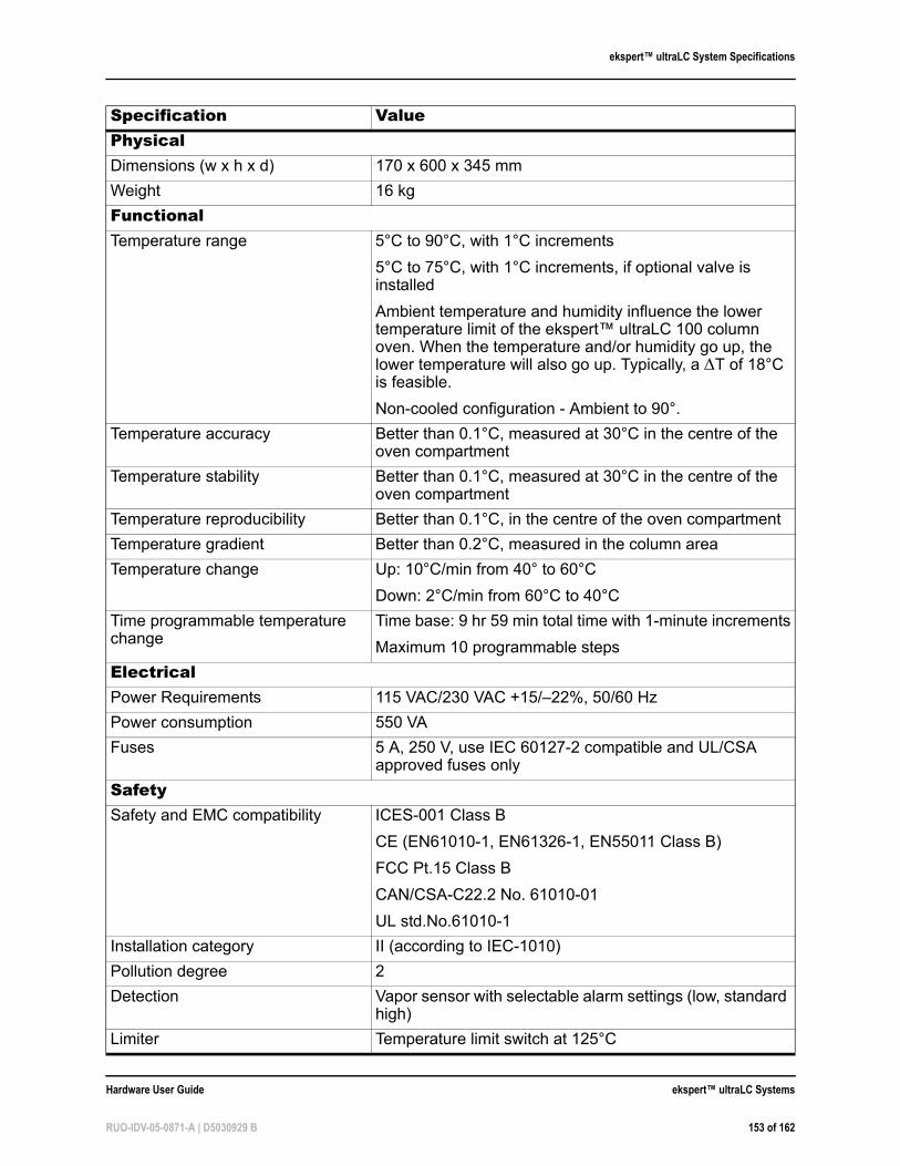
ekspert™ ultraLC System Specifications
PhysicalDimensions (w x h x d) 170 x 600 x 345 mm
Weight 16 kg
FunctionalTemperature range 5°C to 90°C, with 1°C increments
5°C to 75°C, with 1°C increments, if optional valve is installed
Ambient temperature and humidity influence the lower temperature limit of the ekspert™ ultraLC 100 column oven. When the temperature and/or humidity go up, the lower temperature will also go up. Typically, a T of 18°C is feasible.
Non-cooled configuration - Ambient to 90°.
Temperature accuracy Better than 0.1°C, measured at 30°C in the centre of the oven compartment
Temperature stability Better than 0.1°C, measured at 30°C in the centre of the oven compartment
Temperature reproducibility Better than 0.1°C, in the centre of the oven compartment
Temperature gradient Better than 0.2°C, measured in the column area
Temperature change Up: 10°C/min from 40° to 60°C
Down: 2°C/min from 60°C to 40°C
Time programmable temperature change
Time base: 9 hr 59 min total time with 1-minute increments
Maximum 10 programmable steps
ElectricalPower Requirements 115 VAC/230 VAC +15/–22%, 50/60 Hz
Power consumption 550 VA
Fuses 5 A, 250 V, use IEC 60127-2 compatible and UL/CSA approved fuses only
SafetySafety and EMC compatibility ICES-001 Class B
CE (EN61010-1, EN61326-1, EN55011 Class B)
FCC Pt.15 Class B
CAN/CSA-C22.2 No. 61010-01
UL std.No.61010-1
Installation category II (according to IEC-1010)
Pollution degree 2
Detection Vapor sensor with selectable alarm settings (low, standard high)
Limiter Temperature limit switch at 125°C
Specification Value
Hardware User Guide ekspert™ ultraLC Systems
RUO-IDV-05-0871-A | D5030929 B 153 of 162
ekspert™ ultraLC System Specifications
Electronics Watchdog in FPGA for embedded software check.
Specification Value
ekspert™ ultraLC Systems Hardware User Guide
154 of 162 RUO-IDV-05-0871-A | D5030929 B
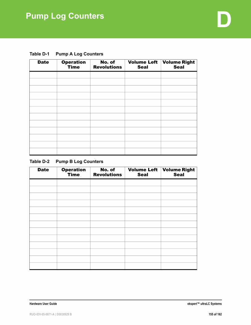
D
Pump Log CountersTable D-1 Pump A Log Counters
Date Operation Time
No. of Revolutions
Volume Left Seal
Volume Right Seal
Table D-2 Pump B Log Counters
Date Operation Time
No. of Revolutions
Volume Left Seal
Volume Right Seal
Hardware User Guide ekspert™ ultraLC Systems
RUO-IDV-05-0871-A | D5030929 B 155 of 162

Pump Log Counters
ekspert™ ultraLC Systems Hardware User Guide
156 of 162 RUO-IDV-05-0871-A | D5030929 B
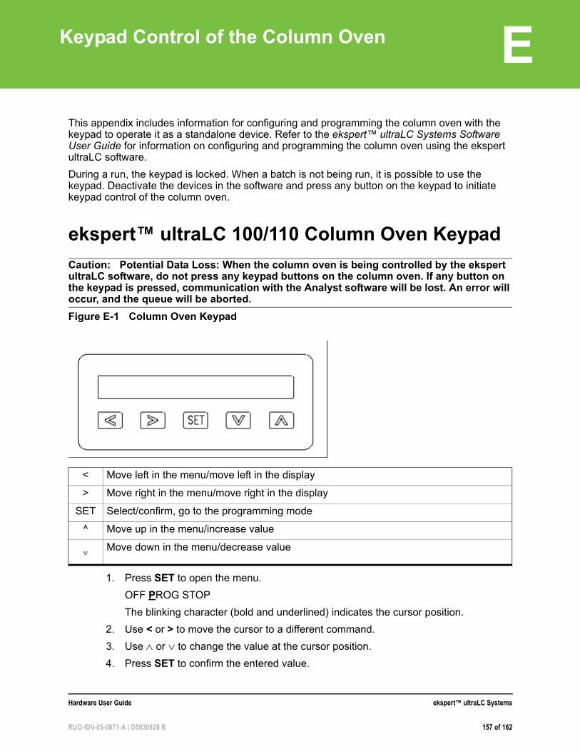
E
Keypad Control of the Column OvenThis appendix includes information for configuring and programming the column oven with the keypad to operate it as a standalone device. Refer to the ekspert™ ultraLC Systems Software User Guide for information on configuring and programming the column oven using the ekspert ultraLC software.
During a run, the keypad is locked. When a batch is not being run, it is possible to use the keypad. Deactivate the devices in the software and press any button on the keypad to initiate keypad control of the column oven.
ekspert™ ultraLC 100/110 Column Oven Keypad
Caution: Potential Data Loss: When the column oven is being controlled by the ekspert ultraLC software, do not press any keypad buttons on the column oven. If any button on the keypad is pressed, communication with the Analyst software will be lost. An error will occur, and the queue will be aborted.
1. Press SET to open the menu.
OFF PROG STOP
The blinking character (bold and underlined) indicates the cursor position.
2. Use < or > to move the cursor to a different command.
3. Use or to change the value at the cursor position.
4. Press SET to confirm the entered value.
Figure E-1 Column Oven Keypad
< Move left in the menu/move left in the display
> Move right in the menu/move right in the display
SET Select/confirm, go to the programming mode
^ Move up in the menu/increase value
Move down in the menu/decrease value
Hardware User Guide ekspert™ ultraLC Systems
RUO-IDV-05-0871-A | D5030929 B 157 of 162
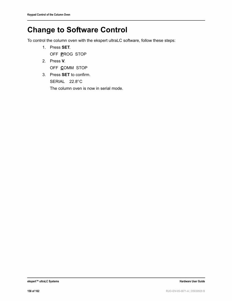
Keypad Control of the Column Oven
Change to Software ControlTo control the column oven with the ekspert ultraLC software, follow these steps:
1. Press SET.
OFF PROG STOP
2. Press V.
OFF COMM STOP
3. Press SET to confirm.
SERIAL 22.8CThe column oven is now in serial mode.
ekspert™ ultraLC Systems Hardware User Guide
158 of 162 RUO-IDV-05-0871-A | D5030929 B
Index
Aacids, list of 11air needle
replacing 91ultraLC 100/110 autosampler, illustrated
22air segment, and flush volume 52alarms, column oven 133autosampler
overview 26performing power wash on 26preparing for storage 120transport 120
Bbases, list of 11bottom cover, removing, ultraLC 100-XL/110-XL autosampler 67Buffer solution 81buffer solution, changing 81buffers, list of 11
Cchanging
buffer solution 81seal wash solvent 59
check valveinlet, illustrated 18outlet, illustrated 18
check valve holders, tightening 76check valve, maintaining 77checking leaks 59cleaning
condensation tubing 105drip tray 102pump surfaces 76seal wash bottles 83ultraLC 100/110 autosampler surface 86wash block 119waste tubing 105
column ovenalarms 133described 34error codes 140
keypad control 37serial control 158software control 36starting 71troubleshooting 133warnings 134
column selection valve, illustrated 35communication connections
100-XL/110-XL autosampler 32condensation tubing, cleaning 105cover, removing, ultraLC 100/110 autosampler64
Ddegasser
illustrated 18tubing 77
degasser, maintaining 81door, opening, ultraLC 100/110 autosampler63drip tray, cleaning 102
Eekspert ultraLC 100 column oven. See columnovenerror codes
column oven 140pump 137ultraLC 100/110 autosampler 137ultraLC 100-XL/110-XL autosampler 139
FFerrule 71ferrule and nut 71flow line, maintaining 76fluids, safe 11foot door, opening, ultraLC 100-XL/110-XLautosampler 67full loop injections
overview 38switching sequence 39
Fuses 101fuses
ultraLC 100/110 autosampler 101ultraLC 100-XL/110-XL autosampler 119
Hardware User Guide ekspert™ ultraLC Systems
RUO-IDV-05-0871-A | D5030929 B 159 of 162
Index
Ggradient separations, flow rates 17
Hheadspace
vials and wells 53
Iinjection modes 38injection needle
100-XL/110-XL autosampler 28injection valve
100-XL/110-XL autosampler 28replacing 86, 107
inlet check valveillustrated 18
installing, supply line 121
Kkeypad 157keypad control, column oven 37
LLC system injection modes 38leak checks 59liquid chromatography, overview 37long-term storage
autosampler 120pump 84
loop, replacing sample loop 88, 110
Mmaintaining
check valves 77degasser 81flow line 76seal wash system 82solvent filters 77
matrixes 69mixer, replacing 82mobile phase solvent, switching 80
Nneedle manifold 28, 29needle wash station, illustrated 22needles
autosampler 29nut and ferrule 71
Oopening the door, ultraLC 100/110autosampler 63opening the foot door, ultraLC 100-XL/110-XLautosampler 67optimizing performance 70organic solvents, list of 11outlet check valve, illustrated 18outlet filter, replacing 78
Ppartial loop injections
overview 42switching sequence 42
performing power wash 26Plunger 98preheater, illustrated 35priming, seal wash 60pump
cleaning surfaces 76described 17error codes 137illustrated 18, 19, 20long-term storage 84purging 58shutting down 61transport 84troubleshooting 123
pump drain connector, illustrated 18pump heads
illustrated 19puncturing air needle, replacing 112purge button, illustrated 18purge valve, illustrated 18purging pump 58
Rremoving
bottom cover, ultraLC 100-XL/110-XLautosampler 67
cover, ultraLC 100/110 autosampler 64waste tubing, ultraLC 100-XL/110-XL
autosampler 102replacing
air needle 91injection valve 86, 107mixer 82outlet filter 78
ekspert™ ultraLC Systems Hardware User Guide
160 of 162 RUO-IDV-05-0871-A | D5030929 B
Index
puncturing air needle 112rotor seal 86, 107sample loop 88, 110sample needle 89, 110syringe 94, 114syringe plunger 98syringe plunger tip 98syringe valve 98, 116
rotor seal, replacing 86, 107
SSafety Data Sheets 10sample containers 70sample handling 68sample loop, replacing 88, 110sample needle
illustrated, ultraLC 100/110 autosampler22
replacing 89, 110sample temperature control 61sample throughput, controlling 61samples, viscous 52sampling compartment 20, 21seal wash bottle, cleaning 83seal wash housing, illustrated 20seal wash solvent, changing 59seal wash system, maintaining 82seal wash, priming 60serial control, column oven 158shutting down the pump 61site requirements 9software control, column oven 36solvent filter
clogged 77maintaining 77
solvent selection valve, illustrated 18starting
column oven 71ultraLC 100/110 autosampler 62ultraLC 100-XL/110-XL autosampler 66
station, needle wash, illustrated 22sticky compounds 69storage
preparing autosampler for 120preparing pump for 84
supply line, installing 121switching mobile phase solvent 80syringe
100-XL/110-XL autosampler 28
illustrated, ultraLC 100/110 autosampler22
replacing 94, 114syringe plunger tip, replacing 98syringe plunger, replacing 98syringe valve
replacing 98, 116ultraLC 100/110 autosampler, illustrated
22system
safe fluids 11
Ttemperature sensor, described 36transport
autosampler 120pump 84
tray carrier, illustrated, ultraLC 100/110autosampler 22troubleshooting
column oven 133pump 123ultraLC 100/110 autosampler 126ultraLC 100-XL/110-XL autosampler 129
UuHPLC 69uL pickup
overview 46switching sequence 47
ultraLC 100 column oven. See column ovenultraLC 100/110 autosampler
cleaning surfaces 86error codes 137starting 62troubleshooting 126
ultraLC 100-XL/110-XL autosamplererror codes 139starting 66troubleshooting 129
Vvalve
column selection, illustrated 35inlet check, illustrated 18outlet check, illustrated 18purge, illustrated 18solvent selection, illustrated 18syringe, illustrated 22
Hardware User Guide ekspert™ ultraLC Systems
RUO-IDV-05-0871-A | D5030929 B 161 of 162
Index
vapor sensor, described 36
Wwarnings, column oven 134wash block, cleaning 119wash station, needle, illustrated 22waste connections, 100-XL/110-XLautosampler 30waste tubing
cleaning 105removing 102ultraLC 100-XL/110-XL autosampler 102
well plates and adapters, 100-XL/110-XLautosampler 32
ekspert™ ultraLC Systems Hardware User Guide
162 of 162 RUO-IDV-05-0871-A | D5030929 B