elastic consolidation around a deep circular tunnel · elastic consolidation around a deep circular...
TRANSCRIPT

fnr I. Solids Ahcfwer Vol. 18. No. 12. pp. lO59-1074. 19112 Prinled in GmI Britain.
m&76831P2/121059-16$03.~ @ 1982 Papm0n Press Ltd.
ELASTIC CONSOLIDATION AROUND A DEEP CIRCULAR TUNNEL
J. P. CARTER
Dapartment of Civil Engineering, University of Queensland, St. Lucia, Queensland, Australia
J. R. BOOKER
Department of Civil Engineering, University of Sydney, Sydney, Australia
(Received 13 July 1981; in nvised form 15 March 1982)
Aimtnct-A method of analysis is presented for the consilidation of a linear elastic soil due to the cutting of a long and deep circular tunnel. Solutions have been obtained for the time dependent displacements and stress changes occurriag in the soil surrounding the tunnel opening.
NOMENCLATURE
A,,A2 ,.... A6 constants c coefficient of consolidation
e,,, e, radial and circumferential strains e, volume strain
E. Fourier coefficient of volume strain G elastic shear modulus
I, Km modified Bessel Functions of order II k permeability coefficient
I& coefiicient of earth pressure at rest n Fourier integer
N ratio of horizontal to vertical total stress p. in sitv pore water pressure p excess pore pressure P Fourier coefficient of excess pore pressure r radii coordinate
q radius of tunnel s Laplace Transform variable f time since tunnel cutting
II,, 4 radial and circumferential displacements U, U, Fourier Coefficients of displacement
S,,, S, S, Fourier Coefficients of stress y,,, shear strain yW unit weight of pore water 0 circumferential coordinate A Lam6 constant for soil skeleton v’ Poisson’s ratio for soil skeleton
cr., one half of the in siru deviator stress a, mean in situ total stress
a, am uH stress components 4 deformation function 4 Fourier Coefficient of 4
q$, & solution functions #,, 6 solution functions
0 rotation 0 Fourier Coefficient of o
1. INTRODUCTION
The problem of a tunnel in saturated clay is of some interest to geotechnical engineers concerned with the design of tunnel linings or tunnel support systems. As a first approximation the soil surrounding the tunnel is often idealised as an isotropic, elastic continuum and some solutions have been obtained for the displacements and stress changes in the elastic medium after tunnel boring, e.g. [ 1, 21.
In the earlier investigations the soil was considered to behave as a single phase mat- erial and hence the solutions obtained are relevant only to the short term
1059 Ss Vol. 18. No. 12--B

1060 J. P. CARTER and J. R. BOOKER
(or undrained) condition and the long term (or fully drained) condition. How- ever, when an opening is created in a saturated medium the resulting displace- ments and stress changes will be time dependent. This time dependence arises because of the two phase nature of a saturated elastic material. Volume change can only take place as water is expelled from the voids between the solid particles. Movement of water through the soil cannot occur instantaneously and so any deformations which involve a change in volume will require a finite time in which to take place. Conversely, any deformations which involve only shearing can occur instantaneously.
In this paper solutions are presented for the displacements and stress changes around a long circular opening in a saturated elastic medium. It is assumed that the time dependence of these changes is due entirely to consolidation of elastic soil. No consideration is given to other time dependent phenomena such as creep.
2. PROBLEM DESCRIPTION
It is assumed that the tunnel will be bored at a depth which is large when compared with the nominal radius of the tunnel opening. To sufficient accuracy the in situ stress state in the ground, prior to tunnel cutting, may be idealised as being uniform with a total normal stress u,, which acts in the vertical direction, and a total normal stress o,,, which acts in all horizontal directions. The horizontal total stress may be expressed as a proportion of the total vertical stress, thus
uH = Nun. (1)
The principle of effective stress gives
U” = u”‘+po
uff=uff’+po
where u”’ and uH’ are vertical and horizontal effective stress components, respectively, and p. is the in situ pore water pressure. Compressive stress is considered to be positive. The coefficient of earth pressure at rest Ko, is defined by
uH’= Koun'. (2)
For a soil deposit with the water table at the surface, and a bulk unit weight y, then
N=Ko-F(Ko-1)
where y,,, is the unit weight of water.
(3)
For the circular opening it is more convenient to express the in situ stress state in terms of polar coordinates, see Fii. 1. It follows that the total stresses acting on a circular boundary are given by
u~=u,+u~cos2o (4a)
u&q=u,-u~cos20 W
u,@ = -ad sin 28 (4c)
where

Elastic consolidation around a deep circular tunnei 1061
Vertical
t
Fig. I. Definition of tunnel problem and coordinate system.
Equations (4) give the stresses which act at the periphery of the tunnel before it is bored. After boring the normal total stress a,, and the shear stress CT& are both removed from the tunnel boundary. Hence the stress boundary conditions for this problem may be idealised as
AUK = -ff,,, -a,, COS 20
AO;B = udsin28 at r= r.
64
(W
where the symbol A indicates a change in the appropriate quantity. It is also necessary to consider the hydraulic boundary conditions at the tunnel wall, since
the soil is saturated. There are two important cases which may be identified. These are:
(a) a permeable tunnel, and (b) an impermeable tunnel.
For these situations the corresponding boundary conditions are
(a) p = 0 at r = r. (6a)
(b) $ = 0 at r = ro. (W
Equations (5) and (6) describe the complete boundary conditions at the tunnel wall, which correspond to the removal of material to form a circular opening. In order to simplify the analysis, the principle of superposition is employed and the following components of the problem are considered.
(a) Permeable tunnel For the permeable tunnel, three separate components may be identified. These are:
Case Ia Au, = -a,,,
Au,= 0 when r = r,.
p= 0 I
Case IIa
Au,= 0
Au,= 0
1
when r = ro.
AP = -PO

1062
Case IIIa
J. P. CARTER and J. R. BOOKER
Aa, = -a,, cos 28
Au, = ad sin 28 when r = ro.
p= 0 J
(b) Impermeable tunnel For the impermeable tunnel only two non-trivial components need be considered. These are:
Case Ib
Au,, = -a,,,
Au,= 0 when I = r.
*= 0 ar
Case IIIb
‘h, = -ad cos 28
Au, = a,, sin 28 when r = r.
$0
It will be demonstrated later that the solutions to Cases la and lb are identical, i.e. they are independent of the hydraulic boundary conditions.
3. GENERAL SOLUTION
Using a polar coordinate system the equations for consolidation of an isotropic, elastic soil under conditions of plane strain may be written:
!?$E+f~+$7+0 (7b)
a,-p=-Ae,-2Ge, (gal
uee-p= -Ae,-2Geee @b)
ufi = -Gy&
where A and G are the Lame parameters for the elastic soil skeleton (compressive stress and compressive pore pressure are taken as positive);
e =!!L+!&!!. lh3 r r ae
1au,+au* 4 --- y*‘7 ae ar r
Pb)
(94
e, = e, + eee (94

Elastic consolidation around a deep circular tunnel
where, for the elastic soil,
1063
C+.(*+2G)+*&Q (1 -24
with k = isotropic permeability coefficient; 7,,, = unit weight of pore fluid; v’ = Poisson’s ratio for the soil skeleton; and where U, and u, are the r and 0 components of displacement respectively, and the symbol “-*’ denotes the Laplace transform of the appropriate quantity, e.g.
c?. = I om exp (-30 e,(t) dt.
The symbol t is used to represent the time elapsed since the instantaneous tunnel boring. In eqns (7) and (8) the symbol A has been omitted for convenience and g,,, uM a, and p are now used to represent changes in the in situ stress state and pore pressure due to tunnel boring. The governing equations may also be written as
where
are the volume strain and rotation. On introducing 4 defined by
p=G4t(At2G)ev
these equations may also be written as
1ao aj ---= r ae ar
aa 13 -=- ar r ae
Solutions shall be sought which have the form:
u, = u, cos (n6 t 4)
Me = u, cos (Ml t e)
p=Pcos(ne+e)
a, = s, co9 (ne t c)
U, = s, cos (net E)
(114
(1 lb)
(W
WV
WC)
Wa)
Wb)
(13c)
(13d)
(13e)

1064
Equations (12) then become
J. P. Cmm and J. R. BOOKER
cM = S, sin (no + 6) e, = I?” cos (ne f e)
0 =nsin(nB+ir)
4=cf,cos(nB+e).
where
B ” =lL(,~)+n 0
rar ’ r p
Equation (14~) is the modified Bessel equation of order n so that
W) (1%)
(13h)
(13i)
(14b)
(14c)
(144
where K,,, Z, are the modified Bessel functions of order n. Equations (14a, b) can be reduced to linear equations with constant coefficients by the
substitution r = exp (t) and it follows that
2G Q, = A,r-” + A/ We)
2G a= Agr-* - A/‘. (14f)
If we now solve eqns (14d-f) for the transforms of displacement coefficients U, U, we find that the general solution can be expressed in terms of six independent solutions:
A, A2
A3
A4
AS
A5
(13
where the terms of matrix M are given in Appendix A and the constants Al to A6 may be found from the appropriate boundary conditions.
In order to recover the coefficients U,, etc. the Laplace transforms given by eqns (15) must be inverted. This can be achieved by an application of the Complex Inversion Theorem, i.e. for
Elastic consolidation around a deep circular tunnel
the general function f(f) the inversion IS given by
1065
where s is a complex variable and C is any contour in the complex plane such that all singularities of I(S) lie to the left of C.
4. SOLUTIONS FOR THE TUNNEL PROBLEM
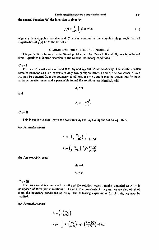
The particular solutions for the tunnel problem, i.e. for Cases I, II and III, may be ob~ined from Equations (IS) after insertion of the relevant boundary conditions.
Case I For case I, n = 0 and e = 0 and thus U, and TM vanish automatically. The solution which
remains bounded as r-*m consists of only two parts; solutions 1 and 5. The constants A, and A, may be obtained from the boundary conditions at r = ro, and it may be shown that for both an impermeable tunnel and a permeable tunnel the solutions are identicai, with
A,=0
and
6J02 AS=- 2G ’
Case II
This is similar to case I with the constants Al and A5 having the following values.
(a) Pe~eabfe r~nnef
A,=- ( ) PO ,L_!- A + 2G s #dro)
@J) I~pe~eabfe tunnel
A,=0
Aj=O.
Case III For this case it is clear n = 2. 6 = 0 and the solution which remains funded as r+m is
composed of three parts; solutions 1, 3 and 5, from the boundary conditions at r = ro. The verified.
The constants At, A3 and A5 are also obtained following expressions for A,, As, A5 may be
(a) Permeable tunnel
A ~1. 3 ( ) x 2Gs

J. P. CARTER and J. R. &JKER
X = ( 5 1 km01 + foWo)l- 1 h+2G
0 j c 1 7 roW0).
5. RESULTS
Explicit solutions for Cases I-III are now presented. Where it has not been possible to invert the Laplace transforms analytically they have been inverted numeri~~y using eqn (16). In all cases the integrand has at most a simple pole at the origin and a branch line extending along the negative real axis and so it has been possible to take the path of integration C around the negative real axis.
Once the coefficients I&, Ue etc are known the co~csponding values of the fieid quantities, i.e. u, u, etc. at location (r, 6) and time t can be retrieved using expressions (13)
Case I The solution in this case is independent of time, the drainage boundary condition at r = r.
and the drained Poisson’s ratio VI. The coefficients of the field quantities are given by,
P ( > - =O urn

Case II
Elastic consolidation around a deep circular tunnel 1067
If the boundary at r = r. is impermeable then the solution for Case II is trivial, i.e. U, = 0, etc. This result does not hold if the boundary at r = r. is permeable. For the latter case only U, = 57, = 0. Isochrones for U, and P are plotted in Figs. 2 and 3, where time has been expressed in a nondimensional form, according to
T=$= ($).2G.(~).$ (17)
When plotted in this form these results are independent of Poisson’s ratio of the soil. The results in Fig. 2 indicate that for large times the magnitude of the radial displacement increases with increasing radius. This feature arises because of the nature of the boundary conditions adopted in the analysis. Specifically, it has been assumed that an indefinite amount of drainage of the pore water may occur at the tunnel boundary r = ro. This is physically unlikely and so the displacement predictions at large times must be considered doubtful. Nevertheless, the results for small and moderate times are likely to be reasonable.
The results presented in Fig. 3 for the pore pressure coefficient P are in good agreement with solutions for the axi-symmetric diffusion (heat flow) problem that have been reported by Jaeger[3]. The pore pressure isochrones are approximately logarithmic functions of radius.
Values for the total stresses a, and u, may be obtained from the results of Figs. 2 and 3 together with the following relations between U, p, a,, and gee, which are valid for all times
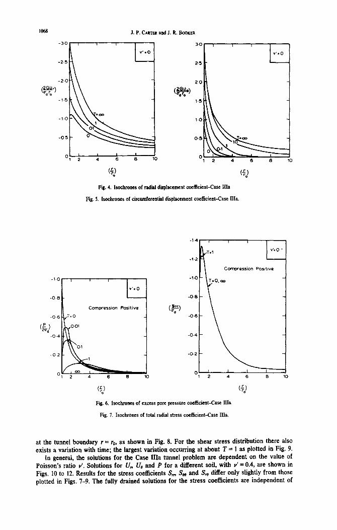
Case III (a) Permeable tunnel Solutions for the coefficients U, U, and P, corresponding to Y’ = 0,
are shown in Fii. 4-6. Isochrones are again plotted for several values of nondimensional time T. Isochrones for the stress coefficients S,,, S, are plotted in Figs. 7-9 for Y’ = 0. In the case of the total radii stress, Fii. 7, the variation with time of the stress distribution is very small. For the total circumferential stress there is a time dependency, with the largest variation occurring
-1 2 4 6 6 l0
-0.6
a\\\ \ -0.6
Compression baitivo -
12 4 6 6 10
Fii. 2. Isochrones of radii displacement coefficient-Case IIa.
Fig. 3. Isochrones of excess pore pressure coefficient-Case Ila.
1068 J. P. CARTGR and J. R. BOOKER
Ol 2 I 4 I 6 I 6 1 10 0 1 2 4 6 6 10
‘$2 ($J
Fii. 4. Isochrones of radial displacement coefficient-Case IIIa
Fii. 5. Isochrones of circumferential displacement coefficient-Case IIIa.
Comprasslon Pcsitwa
Fig. 6. Isocbrones of excess pore pressure coefficient-Case IIIa
Fig. 7. Isochrones of total radial stress coefficient-Case IIIa.
at the tunnel boundary r = ro, as shown in Fii. 8. For the shear stress distribution there also exists a variation with time; the largest variation occurring at about T = 1 as plotted in Fig. 9.
In general, the solutions for the Case IIIa tunnel problem are dependent on the value of Poisson’s ratio v’. Solutions for U, CJ, and P for a different soil, with Y’ = 0.4, are shown in Figs. 10 to 12. Results for the stress coefficients S,.,, S, and S, differ only slightly from those plotted in Figs. 7-9. The fully drained solutions for the stress coefficients are independent of

Elastic consi~~~~ around a deep circular tunnel
I.0
04
Compression Positive
1069
04
0.2
0
-0.2
-04
Fii. 8. Isocbrones of total c~c~feren~l coeI%cient-Case Ma.
Fii. 9. bochr~nc~ of shear stress coefficient-Case IIia,
V’&4
1.x
1.25
1-m
(@I O-75
0.X
0.25
a
L V’XO.
2 4 6 6
Fig. 10. Isochrones of radii displacement coefficient-Case IIIa.
Fig. 11. Isochrones of circumferential displacement-Case IIIa.
Poisson’s ratio and are given by
4

1070 J. P. CARTER and J. R. BOOKER
Compression Positwo
Fig. 12. Isochrones of excess pore pressure coefficient-case Ma.
(b) Impe~eff~fe fenced. Selected results for the case of an impermeable tunnel wall (at r = r,J are shown in Figs. 13-15, where isochrones for U,, U, and P have been plotted for a soil with v’ = 0. Some indication of the effects of the drainage boundary conditions may be gained from a comparison of these results with those of Figs. 4-6.
6. EXAMPLES OF SOLUTION SYNTHESIS
The results presented above were for the individual components of the consolidation problem; the breakdown into these components was described in Section 2. What remains is to assemble the components into a composite solution, In order to ilIus~te the assembty procedure three sets of values have been selected for the in situ stress state. In each example it has been assumed that the soil has a value of u’ = 0.4 and a ratio of unit weights, r,,/r = 0.5. Three values have been selected for the earth pressure coefficient K,, viz. (a) &, = 0.5, (b) K,, = 1, (c) K,, = 2. Values such as these cover a range from normally consolidated clay through to over-consolidated clay. Using eqns (1) and (3) it has been possible to express all stress
-3.0
-2.5
1 t 1
v*. 0
-20
(a!!?) Qd ‘0
- 1.5
-vo \\‘
-05 i‘ I
Ol 2 I L I
4 6 8 10
30
2Glh3 (q$ 1.5
Fig. 13. Isochrones of radial displacement coefficient-Case IIIb.
Fig. I4. Isochrones of circumferential displacement wefticient-Case Wb.

Elastic consilidation around a deep circular tunnel 1071
Comprassion Pmitiva _
Fig. IS. Isochrones of excess pore pressure coefficient-Case IIIb.
quantities in terms of a,, the initial total overburden pressure. (a, is also an indicator of the depth at which the tunnel is bored.) The initial stress conditions are set out in Table 1.
Some results of the synthesis are presented in Table 2 for a tunnel with a permeable inner boundary. Results for the case of an impermeable tunnel are given in Table 3. Both tables show values for the displacements and stresses at selected times and at various locations around the tunnel wall (i.e. r = r. and selected values of 0). The in situ condition corresponds to T = O-; T = O+ corresponds to the instant immediately after the undrained deformation; and T = 03 marks the end of consolidation.
In all of the examples the inner boundary at first “squeezes in” when the in situ stresses are removed, i.e. the tunnel opening becomes smaller during the infinitesimal time interval T = O- to O+. In example (b) the initial stress state is isotropic and so, when the boundary stresses are removed, the resulting displacements are symmetric. At the boundary (r = r,,) no additional movement occurs during the time interval T = O+ to 0 (i.e. during consolidation), although consolidation movements will occur further out in the soil (r > ro).
In examples (a) and (c) the displacements are not symmetric; in (a) the in situ vertical stress is bigger than the horizontal and thus the tunnel “squeezes in” more at the crown and invert (0 = W, 270”) than at the spring line (6 = W, 180”). As consolidation occurs the tunnel wall continues to move in at the crown and invert, but it moves back out at the spring line. The magnitudes of these consolidation movements are small when compared with the initial (undrained) displacements. For example (c) the pattern of movement is the reverse of that just described. The biggest inward movement occurs at the spring line since the in sitlc horizontal stress is bigger than the vertical component. During consolidation, inward movement continues at the spring line but outward movement occurs at the crown and invert.
Table 1. Initial stresses for example problems
Wl*
(4 (b) (cl
0.5 1.0 2.0
0.75 1.0 1.5
0.875 1.0 1.25
0.5 0.5 0.5
- 0.125 0 0.25

1072 J. R. BOOKER and 3. R. BOOKER
Table 2. ~splac~~ents and stresses at the pcrmeabk tunnel wall (v’ = 0.4)
f Brql*
0-
‘-3 w 0+
m
0- u
i
s 0 0+ ”
a
0-
066 ‘0 0+
Y (D
0- 0 25 0
0+ ”
m
-
0- u
r6
T 0'
(D
0-
t 0” ”
m
t-
0-
a ’ *v
-7 0"
0
(4 KG - 0.5 (b) K. - 1.0 (cl K. - 2.0
8 I a* I 8 0 4; 90 0 4; 90 0 4; 90
0 0 0 0 0 0 0 0 0
-0.75 -0.88 -1.0 -1.0 -1.0 -1.0 -1.51 -1.25 -0.99
5.70 -0.88 -1.05 -1.0 -1.0 -1.0 -1.60 -1.25 -0.90
0 0 0 0 0 0 0 0 0
0 -0.i3 0 0 0 0 0 0.26 0
0 -0.18 0 0 0 0 0 0.35 0
0.75 0.88 1.0 1.0 1.0 1.0 1.5 1.25 1.0
0 0 0 0 0 0 0 0 0
0 0 0 0 0 0 0 0 0
1.0 0.88 0.75 f.0 1.0 1.0 1.0 1.25 1.5
2.0 1.58 1.16 1.83 1.83 1.83 1.48 2.33 3.18
2.07 I.58 1.08 1.83 1.83 1.83 1.33 2.33 3.33
0.75 0.75 0.75 1.0 1.0 1.0 1.5 1.5 1.5
0.75 0.58 0.41 0.83 0.83 0.83 1.00 1.33 1.67
0.78 0.58 0.38 0.83 0.83 0.83 0.93 1.33 1.74
0 0.13 0 0 0 0 0 -0.25 0
0 0 0 0 0 0 0 0 0
0 0 0 0 0 0 0 0 0
0.5 0.5 0.5 0.5 0.5 0.5 0.5 0.5 0.5
0 0 0 0 0 0 0 0 0
0 0 0 0 0 0 0 0 0
0.33 0.33 0.33 0.5 0.5 0.5 0.83 0.83 0.83
0.92 0.72 0.52 0.89 0.89 0.89 0.83 1.22 1.62
0.95 0.72 0.49 0.89 0.89 0.89 0.75 1.22 1.69
Typically, it is found that 90% of the consolidation movement will occur during the time interval from T = 0 to about T = 1 for the ‘permeable tunnel and during the interval T = 0 to about T = 10 for the impermeable tunnel. (For a tunnel of radius 2 m in a clay with c = lm’lyr, this means that 90% of the consolidation movement of the wall will have taken place by about 4 yr after the tunnel is bored, if drainage is permitted at the inner boundary, and by about 40 yr if the tunnel walls are impermeable.)
The states of stress in the soil at various points around the inner boundary have also been tabulated at times T = O-, 0' and W. It should be emphasised that all stress quantities presented are cumulative values, incorporating all changes which may have occurred up to the appropriate point in time, Nomin~ly, all of the normal components are total stress values, however, in the case of the permeable inner boundary, the pore pressure is zero for times greater than T = O-. Hence for this case the values are also effective stresses for T a O+. In general, the total circumferential stress is increased at the instant the boundary stresses are removed. During consolidation some further though much smaller changes also occur.
For completeness the tables include values for the total stress component a, which acts in the direction of the tunnel, i.e. perpendicular to the plane containing the circular opening. These values have been computed from the plane strain condition and a knowledge of the pore pressure changes.

Elastic consolidation around a deep circular tunnel
Table 3. ~spla~ements and stresses at the impermeable tunnel wal1 (v’ = 0.4)
_I*
(a) K* - 0.5. (b) Ka - 1.0 (c) 'b - 2.0
Tir e" e" 80
0 45 90 0 45 90 0 45 90
1073
Q-atw
2me avro
a tr
T-
age 0
”
E 0
Y
0 ’ .”
s
0- 0 0 0
0’ -0.75 -0.88 -1.0
m -0.70 -0.88 -1.05
0- 0 0 0
0+ 0 -0.13 0
m 0 -0.18 0
0 0 0
-1.0 -1.0 -1.0
-1.0 -1.0 -1.0
0 0 0
-1.5 -1.25 -1.0
-1.6 -1.25 5.9
0 0 0
0 0 0
0 0 0
0 0 0
0 0.25 0
0 0.35 0
0- 0.75 0.88 1.0
0+ 0 0 0
m 0 0 0
1.0 1.0 1.0 1.5 1.25 1.0
0 0 0 0 0 0
0 0 0 0 0 0
0-
0+
m
~;
0-
0’
m
1.0 0.88 0.75 1.0 1.0 1.0 I
1.0 1.25 1.5
1.5 2.5 3.5 2.25 1.75 1.25 2.0 2.0 2.0
2.25 1.75 1.25 2.0 2.0 2.0 1.s 2.5 3.5
0.75 0.71 0.75 1.0 1.0 1.0 1.5 1.5 1.5
0.99 0.75 0.51 1.0 1.0 1.0 1.19 1.5 1.98
0.95 0.75 0.55 1.0 1.0 1.0 1.10 1.5 1.90
0- 0 0.13 0 0 0 0 0 -0.25 0
0+ 0 0 0 0 0 0 0 0 0
m 0 0 0 0 0 0 0 0 0
0- 0.5 0.5 0.5 0.5 0.5 0.5
0+ 0.72 0.5 0.28 0.5 0.5 0.5
0.5 0.5 0.5
0.06 0 0.94
0.5 0.5 0.5
0.83 0.83 0.83
0.84 1.33 0.89
0.37 0.83 1.3
One particular quantity which tas bern tabuiated and may be of some interest is the average effective stress o!,, = l/3 (a: + ai0 + czz). In all cases an overall increase in this mean stress occurs at the boundary as a result of instantaneous tunnel cutting. During the consolidation phase this mean stress may also vary, with the sign and magnitude of these additional changes varying with the initia1 stress condition (ir,) and with position around the tunnel (4). Except for the soil in the region of the springline of example (c), the net result of tunnel cutting foliowed by consolidation is to cause an increase in mean effective stress at the inner boundary.
7. CON&LUSIONS
A method of analysis has been presented for the consolidation in an elastic soil due to the cutting of a long and deep circular tunnel. Solutions have been presented for the time dependent displacements and stress changes occurring in the soil surrounding the opening. No consideration has been given to the effects of introducing a tunnel lining or of creep and plastic flow within the soil. Such features are currently under investigation.
REFERENCES 1. A. M. Muir Wood, The circular tunnel in elastic ground. G&~~~~ue U(l), 115-127 (1975). 2. hi. 1. Fender, Elastic solutions for a deep circular tunnel. ~tec~~que B(2), 216-222 (l!BO). 3. J. C. Jaeger, Numerical values for the temperature in radial heat flow. J. Moths Phys. 34,316321. (1956).

1074 J. P. GARTER and J. R. BSMKER
APPENDIX
The Six independent solutions which are embodied in Equations (15) may be derived after consideration of the following four classes of problem.
(a) Assuming Q, = fl = 0 provides solutions I and 2. (b) Assuming E, = 0 and fl = 8 provides solution 3 (for n # I). (c) Assuming E, = 0 and R = -0 provides solution 4 (for n f -1). (d) Assuming E, = R = P = 0 provides solutions 5 and 6. The matrix M of eqn (IS), which corresponds to these solutions is set out below.
0
0