elasto-plastic stresses in a functionally graded rotating …bhaghpan/papers/elasto-plastic stresses...
TRANSCRIPT
Babak Haghpanah Jahromi
Hamid Nayeb-Hashemi
Ashkan Vaziri1
e-mail:[email protected]
Department of Mechanical and
Industrial Engineering,
Northeastern University,
Boston, MA 02115
Elasto-Plastic Stressesin a Functionally GradedRotating DiskA numerical method based on the extension of the variable material property method wasdeveloped to obtain the elasto-plastic stress field in a functionally graded (FG) rotatingdisk. The method was applied to estimate the stress field in a metal–ceramic functionallygraded solid disk. To establish the validity of the proposed method, results were comparedwith finite element results. Unlike uniform rotating disks, where yielding starts from thedisk center, plasticity in FG disks can originate at any point. The effect of different metal–ceramic grading patterns as well as the relative elastic moduli and densities of the ceramicand metallic constituents on the developed stresses were studied. Reinforcement of a metaldisk with ceramic particles, in both elastic and plastic regimes, can significantly influencethe mechanical response of the disk such as the stress distribution and the critical angularvelocities corresponding to the onset of plasticity in the disk and plastic disk. Disks withincreasing ceramic content from inner to outer radius showed a more uniform von Misesstress distribution for a fixed value of total ceramic content. In contrast, disks withdecreasing ceramic content from inner to outer radius had the lowest outer edge displace-ment for a fixed value of total ceramic content. [DOI: 10.1115/1.4006023]
Keywords: rotating disks, elasto-plastic analysis, functionally graded material, variablematerial properties method, analytical and numerical methods
1 Introduction
Rotating disks have broad applications in gas turbines, highspeed gears, fly wheels, and compact discs. Optimizing the designof a rotating disk and also assessing the failure risk require under-standing its behavior in the elasto-plastic regime. In this context,numerical and analytical investigations have been extensivelyused to predict the deformation, failure, and stress and strain fieldsin a uniform rotating disk under different loading conditions (e.g.,see Refs. [1–7]). The stress field in a uniform rotating disk—underelastic or elasto-plastic loading condition—is not uniform and themaximum stress occurs at the center of the disk. The nonuniformdistribution of stresses is a key barrier in designing rotating diskswith enhanced performance (e.g., minimum weight design, maxi-mum stored energy, minimum outer edge displacement, and uni-form stress distribution). One avenue for addressing this challengeis to vary the thickness and/or density of the rotating disk along itsradius to make the stress distribution near-uniform [8–13]. How-ever, excessive manufacturing costs of such disks at high preci-sion and restrictions due to the curved geometry generally makethis solution infeasible. An alternative approach is to use materialswith varying properties [14–16]. In this context, FG materials arepromising candidates as they avoid the negative effects of abruptchanges in the material constituent due to their unique composi-tion. Moreover, the manufacturing of FG disks with radially vary-ing properties is technically possible by controlling the relativedistribution of the disk material constituents (e.g., reinforcementparticles and metal matrix) using techniques such as the centrifu-gal casting process [17–20].
The analysis of rotating objects (disk, shafts, beams, etc.) withvarying material properties is generally challenging, since the
interaction between different deformation modes could lead to acomplex state of stress and deformation, including out of planedeformation, vibration, warping, and instability [21–26]. For adisk with material variation in the radial direction, the structurecan be discretized to uniform rings of different radii with infinites-imal width. The elastic analysis for stress and deformation fieldsin a FG rotating disk with exponentially and parabolically varyingelastic modulus in the radial direction is presented by Eraslan andAkis [27]. Similar semi-analytical and numerical studies havebeen carried out for FG elastic disks [28–31]. In this study, weprovide an analytical method for estimating the elasto-plasticstresses in a rotating disk with varying elastic and plastic proper-ties in the radial direction. The proposed method is an extensionof the variable material properties (VMP) method [32,33], and isdiscussed in Sec. 2. In this method, the functionally graded mate-rial parameters are considered as field variables and the linearelastic solution of a boundary value problem is used to generatethe inelastic solution in an iterative manner. The analysis methodis applicable to both hollow and solid disks with different bound-ary conditions, multilayered rotating disks, disks with temperaturegradients, and disks with varying thicknesses and material proper-ties, as long as the problem has an axisymmetric condition. Thismethod is generally very effective and the solution can beobtained after few iterations. The method also yields accurate sol-utions for the elasto-plastic stress distributions compared to otherapproaches such as the semi-analytical method presented by Youand Zhang [1] for uniform elasto-plastic disks as explained inSec. 3. In Sec. 4, we applied the method developed to analyze theelasto-plastic stresses in a FG rotating disk reinforced with ce-ramic particles. In this study, the constituent material of the rotat-ing disk is considered to be a metal–ceramic composite withvarious ceramic volume fractions through the disk radius. Aselected set of finite element calculations were done to establishthe validity of the proposed method using the commercially avail-able software ABAQUS. A parametric study was carried out to studythe effect of variation of material properties on the distribution of
1Corresponding author.Contributed by the Materials Division of ASME for publication in the JOURNAL OF
ENGINEERING MATERIALS AND TECHNOLOGY. Manuscript received April 4, 2011; finalmanuscript received January 30, 2012; published online March 26, 2012. Assoc.Editor: Georges Cailletaud.
Journal of Engineering Materials and Technology APRIL 2012, Vol. 134 / 021004-1Copyright VC 2012 by ASME
Downloaded 02 Apr 2012 to 129.10.66.174. Redistribution subject to ASME license or copyright; see http://www.asme.org/terms/Terms_Use.cfm
stresses inside the rotating disk. The conclusions are drawn inSec. 5.
2 Theoretical Model
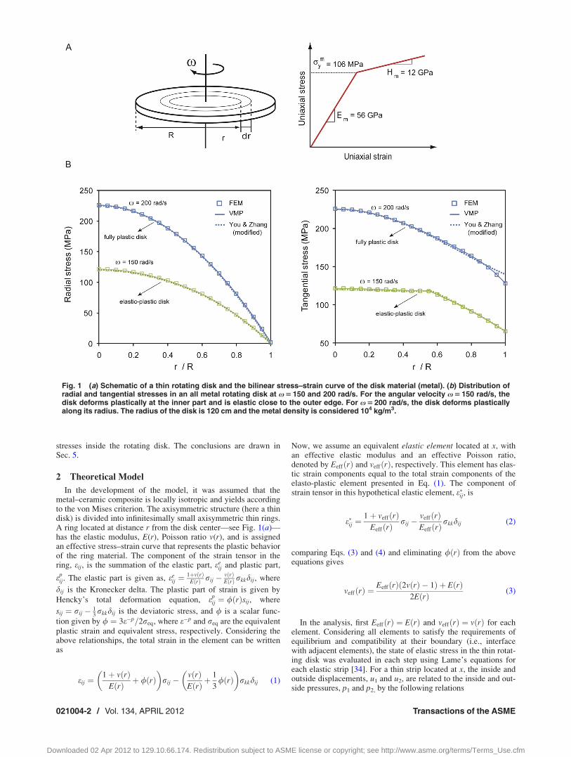
In the development of the model, it was assumed that themetal–ceramic composite is locally isotropic and yields accordingto the von Mises criterion. The axisymmetric structure (here a thindisk) is divided into infinitesimally small axisymmetric thin rings.A ring located at distance r from the disk center—see Fig. 1(a)—has the elastic modulus, E(r), Poisson ratio v(r), and is assignedan effective stress–strain curve that represents the plastic behaviorof the ring material. The component of the strain tensor in thering, eij, is the summation of the elastic part, ee
ij and plastic part,
epij. The elastic part is given as, ee
ij ¼1þvðrÞ
EðrÞ rij � vðrÞEðrÞrkkdij, where
dij is the Kronecker delta. The plastic part of strain is given by
Hencky’s total deformation equation, epij ¼ /ðrÞsij, where
sij ¼ rij � 13rkkdij is the deviatoric stress, and / is a scalar func-
tion given by / ¼ 3e�p=2req, where e�p and req are the equivalentplastic strain and equivalent stress, respectively. Considering theabove relationships, the total strain in the element can be writtenas
eij ¼1þ vðrÞ
EðrÞ þ /ðrÞ� �
rij �vðrÞEðrÞ þ
1
3/ðrÞ
� �rkkdij (1)
Now, we assume an equivalent elastic element located at x, withan effective elastic modulus and an effective Poisson ratio,denoted by EeffðrÞ and veffðrÞ, respectively. This element has elas-tic strain components equal to the total strain components of theelasto-plastic element presented in Eq. (1). The component ofstrain tensor in this hypothetical elastic element, e�ij, is
e�ij ¼1þ veffðrÞ
EeffðrÞrij �
veffðrÞEeffðrÞ
rkkdij (2)
comparing Eqs. (3) and (4) and eliminating /ðrÞ from the aboveequations gives
veffðrÞ ¼EeffðrÞð2vðrÞ � 1Þ þ EðrÞ
2EðrÞ (3)
In the analysis, first EeffðrÞ ¼ EðrÞ and veffðrÞ ¼ vðrÞ for eachelement. Considering all elements to satisfy the requirements ofequilibrium and compatibility at their boundary (i.e., interfacewith adjacent elements), the state of elastic stress in the thin rotat-ing disk was evaluated in each step using Lame’s equations foreach elastic strip [34]. For a thin strip located at x, the inside andoutside displacements, u1 and u2, are related to the inside and out-side pressures, p1 and p2, by the following relations
Fig. 1 (a) Schematic of a thin rotating disk and the bilinear stress–strain curve of the disk material (metal). (b) Distribution ofradial and tangential stresses in an all metal rotating disk at x 5 150 and 200 rad/s. For the angular velocity x 5 150 rad/s, thedisk deforms plastically at the inner part and is elastic close to the outer edge. For x 5 200 rad/s, the disk deforms plasticallyalong its radius. The radius of the disk is 120 cm and the metal density is considered 104 kg/m3.
021004-2 / Vol. 134, APRIL 2012 Transactions of the ASME
Downloaded 02 Apr 2012 to 129.10.66.174. Redistribution subject to ASME license or copyright; see http://www.asme.org/terms/Terms_Use.cfm
u1
u2
� �¼ C11 C12
C21 C22
� �� p1
p2
� �þ k1
k2
� �(4)
where in the plane stress case
C11;r ¼1þ veffðrÞ
EeffðrÞr3
ðr þ drÞ2 � r2
1� veffðrÞ1þ veffðrÞ
þ ðr þ drÞ2
r2
!
C12;r ¼�2
EeffðrÞrðr þ drÞ2
ðr þ drÞ2 � r2
C21;r ¼2
EeffðrÞðr þ drÞr2
ðr þ drÞ2 � r2
C22;r ¼ �1þ veffðrÞ
EeffðrÞðr þ drÞ3
ðr þ drÞ2 � r2
1� veffðrÞ1þ veffðrÞ
þ r2
ðr þ drÞ2
!
and
K1 ¼qðrÞ � x2 � ð1� veffðrÞÞ2
8EeffðrÞ� 3þ veffðrÞ
1þ veffðrÞþ ðr2 þ ðr þ drÞ2Þ
�
� r þ 3þ veffðrÞ1� veffðrÞ
� ðr þ drÞ2r � r3
�
K2 ¼qðrÞ � x2 � ð1� veffðrÞÞ2
8EeffðrÞ� 3þ veffðrÞ
1þ veffðrÞþ ðr2 þ ðr þ drÞ2Þ
�
� ðr þ drÞ þ 3þ veffðrÞ1� veffðrÞ
� r2ðr þ drÞ � ðr þ drÞ3�
(5)
where r and (rþ dr) are the inner and outer radii of the strip. Afterassembling all strips together, a system of linear equations of theform ½C0�fUg ¼ fPg þ fK0g is obtained, where fUg is the radialdisplacement vector of the strips at their interface, fPg is theinterfacial pressure vector, and fK0g is the matrix denoting thecontribution of the inertia. Solving this equation gives fUg.
Next, EeffðrÞ is updated by applying the projection method foreach element based on the calculated equivalent (von Mises)
stress [33] (i.e., EeffðrÞ ¼ rðeeffÞeeff
, where the function rðeÞ represents
the effective stress–strain curve of the material at distance r). Theeffective Poisson ratio for each element, veffðrÞ, is obtained usingEq. (3). In the next step, the state of stress in each element isrecalculated using the updated values of effective elastic modulusand effective Poisson’s ratio. This procedure is continued until theconvergence to the stress solution is achieved.
Several models have been proposed for estimating the linearand nonlinear response of particulate composites, which are capa-ble of predicting the effective mechanical properties of the com-posite material with high fidelity for relatively simplemicrostructures or low volume fraction of one of the constituents[35–41]. More complex models of materials with varying elasticand plastic properties have taken into consideration the effect ofmaterial gradation, microstructure, and the interactions betweenthe material constituents [42–48]. Here, we assumed that themetal matrix has bilinear elastic–plastic behavior with density,qm, elastic modulus, Em, tangent modulus, Hm, and yield stress,rm
y . The ceramic was assumed to have density, qc, and be linearelastic with elastic modulus, Ec. We estimated the material prop-erties of the metal–ceramic composite (density, qmc; elastic modu-lus, Emc; overall flow strength of the composite corresponding tothe onset of yielding, rmc
y ; tangent modulus of the composite rep-resenting its strain hardening behavior, Hmc) using the modifiedrule of mixture for composites [49]
qmc ¼ ð1� f Þqm þ fqc
Emc ¼ ð1� f Þ qþ Ec
qþ Em
� �þ f
� ��1
� ð1� f ÞEmqþ Ec
qþ Em
� �þ fEc
� �
rmcy ¼ rm
y ð1� f Þ þ qþ Em
qþ Ec
� �� Ec
Em� f
� �
Hmc ¼ ð1� f Þ qþ Ec
qþHm
� �þ f
� ��1
� ð1� f ÞHmqþ Ec
qþHm
� �þ fEc
� �(6)
where f denotes the volume fraction of the ceramic particles andq is the so called stress to strain transfer ratio, a parameterwhich is independent of f and defines the metal/ceramic interfacebehavior [49].
In all the calculations presented here, the metal component ofthe FG material has Em¼ 56 GPa, Hm¼ 12 GPa, rm
y ¼ 106 MPa,density qm¼ 104 kg/m3, and the Poisson ratio is assumed to beconstant and equal to 0.25 [50]. The density and elastic modulusof ceramic were varied systematically in the ranges of�5 GPa–560 GPa (i.e., 0.1<Ec/Em< 10) and 102 kg/m3–104 kg/m3
(i.e., 0.1<qc/qm< 10), respectively. The values of ceramic densityand ceramic modulus of elasticity qc¼ 104 kg/m3 and Ec¼ 80 GPawere taken in the calculations as default, respectively. The ceramicPoisson’s ratio was considered to be 0.25. The value of q is takenas 17.2 GPa based on the micro-indentation experiments byGu et al. [50].
To account for a wide range of possible distribution patterns ofceramic particles, two different power-law distributions for the ce-ramic volume fraction were considered:
(i) A rotating disk with a monotonic increase in the ceramicvolume fraction from 0 at its center to fo at the outer radius
fcðrÞ ¼ for
R
� n0 � fo � 1; n > 0 (7)
where R is the disk radius, fcðrÞ is the ceramic volume fraction atdistance r from the disk center, and n is the exponent of the ce-ramic volume fraction distribution function. (ii) A rotating diskwith a monotonic decrease in the ceramic volume fraction from fiat its center to 0 at the outer radius.
fcðrÞ ¼ fiR� r
R
� �n
0 � fi � 1; n > 0 (8)
fo¼ 0 in Eq. (1) and fi¼ 0 in Eq. (2) denote a metallic disk andn¼ 0 in both equations denotes a uniformly reinforced metal–-ceramic disk.
3 Stresses in a Uniform Rotating Disk
Figure 1 shows the stresses distribution in a uniform elasto-plastic rotating disk obtained from three different methods,namely, finite element analysis, a modified form of the semi-analytical method introduced by You and Zhang [1], and theVMP method outlined in Sec. 2. The material is considered tobehave according to a bilinear stress–strain curve (e.g., linearstrain hardening behavior) with the properties shown in Fig. 1(a).
The analytical method proposed by You and Zhang [1] is basedon the assumption that the stresses induced in a solid uniformrotating disk of constant thickness can be estimated by a polyno-mial of the even powers of radius r. The polynomial terms areobtained by satisfying the requirement of compatibility and equi-librium. For a rotating disk made of a material with linear strainhardening in the plastic regime, however, the method presented inRef. [1] does not show a good agreement with the results obtained
Journal of Engineering Materials and Technology APRIL 2012, Vol. 134 / 021004-3
Downloaded 02 Apr 2012 to 129.10.66.174. Redistribution subject to ASME license or copyright; see http://www.asme.org/terms/Terms_Use.cfm
from the finite element analysis. To enhance the accuracy of themethod, You and Zhang estimated the linear strain hardeningbehavior with a nonlinear, polynomial form of stress–plastic straincurve at small plastic strains.
We have re-evaluated the work by You and Zhang and noticedthat the error in the results for a linear strain hardening behaviorcan be avoided by simplifying the boundary conditions of govern-ing equation. This simplification results in a significant reductionof the complexity of the equations that should be solved and theassociated numerical errors. The details of the modified solutionmethod are presented in Appendix. The radial stress distributionsobtained from the three methods show a good agreement for bothelasto-plastic and fully plastic disks, Fig. 1(c). However, themodified You and Zhang method could not predict the tangentialstresses close to the outer edge of the disk with high fidelity.According to the results shown, the VMP method is capable ofpredicting stresses in both elasto-plastic and fully plastic diskswith high fidelity.
4 Stresses in a FG Rotating Disk
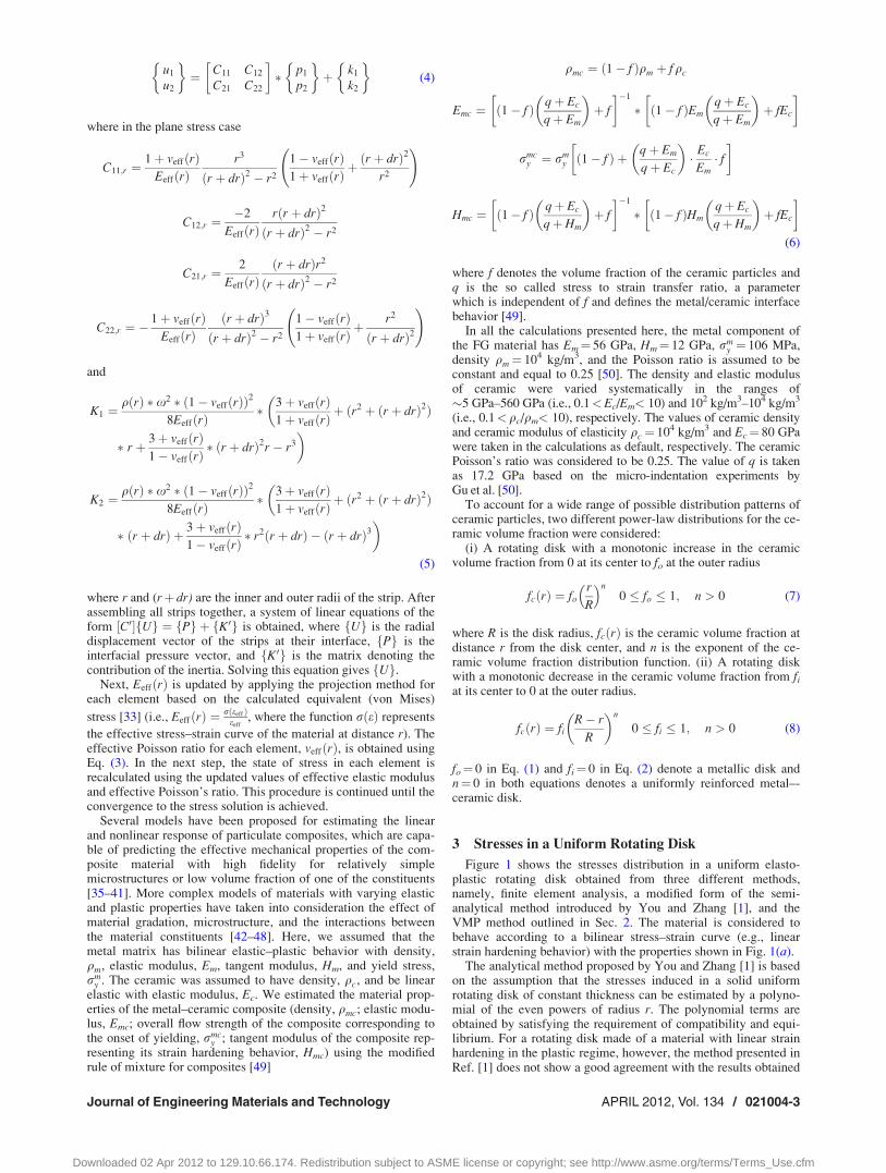
In Fig. 2, the distribution of the principal and von Mises stressesin a FG disk with a linear decrease in the ceramic content in the
radial direction (fi¼ n¼ 1) and a FG disk with a linear increase inthe ceramic content in the radial direction (fo¼ n¼ 1) are plottedand compared to the stress distribution in a uniform metal disk foran angular velocity of x¼ 400 rad/s. At this angular velocity,entire sections of the three disks undergo plastic deformation.Finite element results are also presented for these cases. For finiteelement modeling of the FG rotating disk, the thin disk wasdivided into 50 axisymmetric, concentric rings, and each ring wasassigned with a material property associated with the materialproperty of the material at the midradius of the ring using Eq. (6).The model was meshed using two-dimensional, eight-node quad-rilateral elements and mesh sensitivity analysis was performed toassure that the results are not sensitive to the ring size or meshing.The results obtained from the developed method show excellentagreement with the finite element calculations. The advantage ofthe proposed method over the finite elements analysis is the com-putational simplicity and efficiency for parametric and optimiza-tion studies.
The disk with fo¼ n¼ 1 has the lowest stress at the center anddevelops relatively uniform hoop and von Mises stress distribu-tions. In contrast, the disk with fi¼ n¼ 1 has higher stresses at itscenter compared to the uniform (all metal) disk and a stronglynonuniform stress distribution. Further analysis of a FG rotating
Fig. 2 Distribution of (a) radial, (b) hoop, and (c) von Mises stresses for a FG metal–ceramic rotating disk subjected to x 5 400rad/s for different reinforcement distributions. The radius of the disk is 120 cm.
021004-4 / Vol. 134, APRIL 2012 Transactions of the ASME
Downloaded 02 Apr 2012 to 129.10.66.174. Redistribution subject to ASME license or copyright; see http://www.asme.org/terms/Terms_Use.cfm
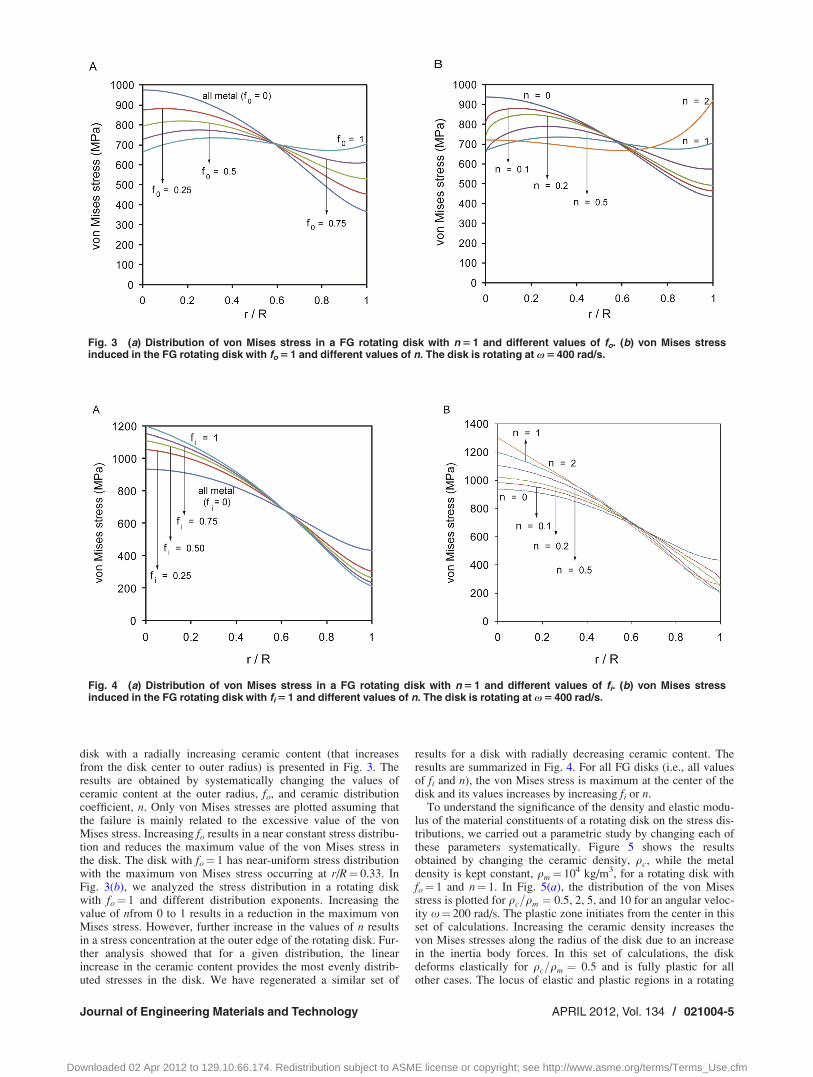
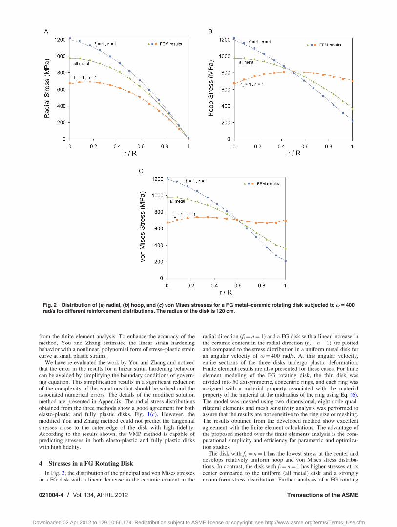
disk with a radially increasing ceramic content (that increasesfrom the disk center to outer radius) is presented in Fig. 3. Theresults are obtained by systematically changing the values ofceramic content at the outer radius, fo, and ceramic distributioncoefficient, n. Only von Mises stresses are plotted assuming thatthe failure is mainly related to the excessive value of the vonMises stress. Increasing fo results in a near constant stress distribu-tion and reduces the maximum value of the von Mises stress inthe disk. The disk with fo¼ 1 has near-uniform stress distributionwith the maximum von Mises stress occurring at r/R¼ 0.33. InFig. 3(b), we analyzed the stress distribution in a rotating diskwith fo¼ 1 and different distribution exponents. Increasing thevalue of nfrom 0 to 1 results in a reduction in the maximum vonMises stress. However, further increase in the values of n resultsin a stress concentration at the outer edge of the rotating disk. Fur-ther analysis showed that for a given distribution, the linearincrease in the ceramic content provides the most evenly distrib-uted stresses in the disk. We have regenerated a similar set of
results for a disk with radially decreasing ceramic content. Theresults are summarized in Fig. 4. For all FG disks (i.e., all valuesof fi and n), the von Mises stress is maximum at the center of thedisk and its values increases by increasing fi or n.
To understand the significance of the density and elastic modu-lus of the material constituents of a rotating disk on the stress dis-tributions, we carried out a parametric study by changing each ofthese parameters systematically. Figure 5 shows the resultsobtained by changing the ceramic density, qc, while the metaldensity is kept constant, qm¼ 104 kg/m3, for a rotating disk withfo¼ 1 and n¼ 1. In Fig. 5(a), the distribution of the von Misesstress is plotted for qc=qm ¼ 0.5, 2, 5, and 10 for an angular veloc-ity x¼ 200 rad/s. The plastic zone initiates from the center in thisset of calculations. Increasing the ceramic density increases thevon Mises stresses along the radius of the disk due to an increasein the inertia body forces. In this set of calculations, the diskdeforms elastically for qc=qm ¼ 0.5 and is fully plastic for allother cases. The locus of elastic and plastic regions in a rotating
Fig. 3 (a) Distribution of von Mises stress in a FG rotating disk with n 5 1 and different values of fo. (b) von Mises stressinduced in the FG rotating disk with fo 5 1 and different values of n. The disk is rotating at x 5 400 rad/s.
Fig. 4 (a) Distribution of von Mises stress in a FG rotating disk with n 5 1 and different values of fi. (b) von Mises stressinduced in the FG rotating disk with fi 5 1 and different values of n. The disk is rotating at x 5 400 rad/s.
Journal of Engineering Materials and Technology APRIL 2012, Vol. 134 / 021004-5
Downloaded 02 Apr 2012 to 129.10.66.174. Redistribution subject to ASME license or copyright; see http://www.asme.org/terms/Terms_Use.cfm
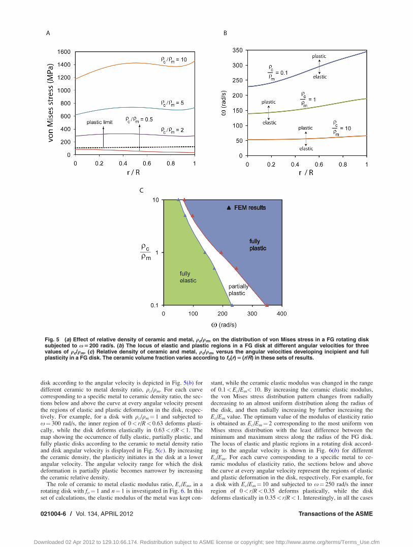
disk according to the angular velocity is depicted in Fig. 5(b) fordifferent ceramic to metal density ratio, qc/qm. For each curvecorresponding to a specific metal to ceramic density ratio, the sec-tions below and above the curve at every angular velocity presentthe regions of elastic and plastic deformation in the disk, respec-tively. For example, for a disk with qc/qm¼ 1 and subjected tox¼ 300 rad/s, the inner region of 0< r/R< 0.63 deforms plasti-cally, while the disk deforms elastically in 0.63< r/R< 1. Themap showing the occurrence of fully elastic, partially plastic, andfully plastic disks according to the ceramic to metal density ratioand disk angular velocity is displayed in Fig. 5(c). By increasingthe ceramic density, the plasticity initiates in the disk at a lowerangular velocity. The angular velocity range for which the diskdeformation is partially plastic becomes narrower by increasingthe ceramic relative density.
The role of ceramic to metal elastic modulus ratio, Ec/Em, in arotating disk with fo¼ 1 and n¼ 1 is investigated in Fig. 6. In thisset of calculations, the elastic modulus of the metal was kept con-
stant, while the ceramic elastic modulus was changed in the rangeof 0.1<Ec/Em< 10. By increasing the ceramic elastic modulus,the von Mises stress distribution pattern changes from radiallydecreasing to an almost uniform distribution along the radius ofthe disk, and then radially increasing by further increasing theEc/Em value. The optimum value of the modulus of elasticity ratiois obtained as Ec/Em¼ 2 corresponding to the most uniform vonMises stress distribution with the least difference between theminimum and maximum stress along the radius of the FG disk.The locus of elastic and plastic regions in a rotating disk accord-ing to the angular velocity is shown in Fig. 6(b) for differentEc/Em. For each curve corresponding to a specific metal to ce-ramic modulus of elasticity ratio, the sections below and abovethe curve at every angular velocity represent the regions of elasticand plastic deformation in the disk, respectively. For example, fora disk with Ec/Em¼ 10 and subjected to x¼ 250 rad/s the innerregion of 0< r/R< 0.35 deforms plastically, while the diskdeforms elastically in 0.35< r/R< 1. Interestingly, in all the cases
Fig. 5 (a) Effect of relative density of ceramic and metal, qc/qm, on the distribution of von Mises stress in a FG rotating disksubjected to x 5 200 rad/s. (b) The locus of elastic and plastic regions in a FG disk at different angular velocities for threevalues of qc/qm. (c) Relative density of ceramic and metal, qc/qm, versus the angular velocities developing incipient and fullplasticity in a FG disk. The ceramic volume fraction varies according to fc(r) 5 (r/R) in these sets of results.
021004-6 / Vol. 134, APRIL 2012 Transactions of the ASME
Downloaded 02 Apr 2012 to 129.10.66.174. Redistribution subject to ASME license or copyright; see http://www.asme.org/terms/Terms_Use.cfm
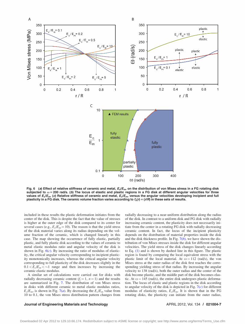
included in these results the plastic deformation initiates from thecenter of the disk. This is despite the fact that the value of stressesis higher at the outer edge of the disk compared to its center forseveral cases (e.g., Ec/Em¼ 10). The reason is that the yield stressof the disk material varies along its radius depending on the vol-ume fraction of the ceramic, which is changed linearly in thiscase. The map showing the occurrence of fully elastic, partiallyplastic, and fully plastic disk according to the values of ceramic tometal elastic modulus ratio and angular velocity of the disk isshown in Fig. 6(c). By increasing the ratio of modulus of elastic-ity, the critical angular velocity corresponding to incipient plastic-ity monotonically increases, whereas the critical angular velocitycorresponding to full plasticity of the disk decreases slightly in the0.1<Ec/Em<�1 range and then increases by increasing theceramic elastic modulus.
A similar set of calculations were carried out for disks withradially decreasing ceramic content (fi¼ 1, n¼ 1) and the resultsare summarized in Fig. 7. The distribution of von Mises stressin disks with different ceramic to metal elastic modulus ratios,Ec/Em, is shown in Fig. 7(a). By decreasing the Ec/Em value from10 to 0.1, the von Mises stress distribution pattern changes from
radially decreasing to a near-uniform distribution along the radiusof the disk. In contrast to a uniform disk and FG disk with radiallyincreasing ceramic content, the plasticity does not necessarily ini-tiate from the center in a rotating FG disk with radially decreasingceramic content. In fact, the locus of the incipient plasticitydepends on the distribution of material properties inside the diskand the disk thickness profile. In Fig. 7(b), we have shown the dis-tribution of von Mises stresses inside the disk for different angularvelocities. The yield stress of the disk changes linearly accordingto Eq. (1) and is shown by dashed line in this figure. The plasticregion is found by comparing the local equivalent stress with theplastic limit of the local material. At x¼ 112 (rad/s), the vonMises stress at the outer radius of the disk first reaches the corre-sponding yielding stress of that radius. By increasing the angularvelocity to 138 (rad/s), both the outer radius and the center of thedisk become plastic, and the middle part of the disk becomes elas-tic. At x¼ 145 (rad/s), the entire disk undergoes plastic deforma-tion. The locus of elastic and plastic regions in the disk accordingto angular velocity of the disk is depicted in Fig. 7(c) for differentmodulus of elasticity ratios, Ec/Em. It is shown that in the FGrotating disks, the plasticity can initiate from the outer radius,
Fig. 6 (a) Effect of relative stiffness of ceramic and metal, Ec/Em, on the distribution of von Mises stress in a FG rotating disksubjected to x 5 200 rad/s. (b) The locus of elastic and plastic regions in a FG disk at different angular velocities for threevalues of Ec/Em. (c) Relative stiffness of ceramic and metal, Ec/Em, versus the angular velocities developing incipient and fullplasticity in a FG disk. The ceramic volume fraction varies according to fc(r) 5 (r/R) in these sets of results.
Journal of Engineering Materials and Technology APRIL 2012, Vol. 134 / 021004-7
Downloaded 02 Apr 2012 to 129.10.66.174. Redistribution subject to ASME license or copyright; see http://www.asme.org/terms/Terms_Use.cfm
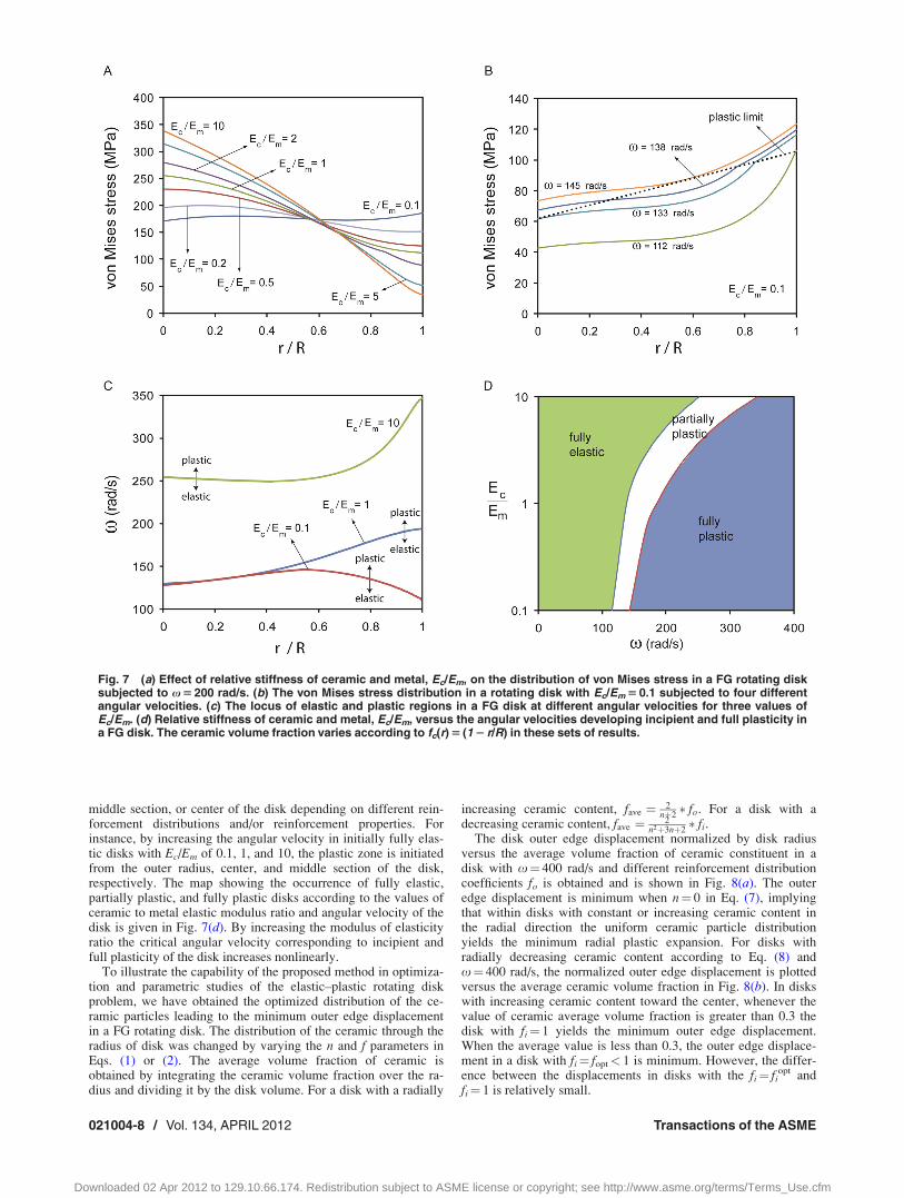
middle section, or center of the disk depending on different rein-forcement distributions and/or reinforcement properties. Forinstance, by increasing the angular velocity in initially fully elas-tic disks with Ec/Em of 0.1, 1, and 10, the plastic zone is initiatedfrom the outer radius, center, and middle section of the disk,respectively. The map showing the occurrence of fully elastic,partially plastic, and fully plastic disks according to the values ofceramic to metal elastic modulus ratio and angular velocity of thedisk is given in Fig. 7(d). By increasing the modulus of elasticityratio the critical angular velocity corresponding to incipient andfull plasticity of the disk increases nonlinearly.
To illustrate the capability of the proposed method in optimiza-tion and parametric studies of the elastic–plastic rotating diskproblem, we have obtained the optimized distribution of the ce-ramic particles leading to the minimum outer edge displacementin a FG rotating disk. The distribution of the ceramic through theradius of disk was changed by varying the n and f parameters inEqs. (1) or (2). The average volume fraction of ceramic isobtained by integrating the ceramic volume fraction over the ra-dius and dividing it by the disk volume. For a disk with a radially
increasing ceramic content, fave ¼ 2nþ2� fo. For a disk with a
decreasing ceramic content, fave ¼ 2n2þ3nþ2
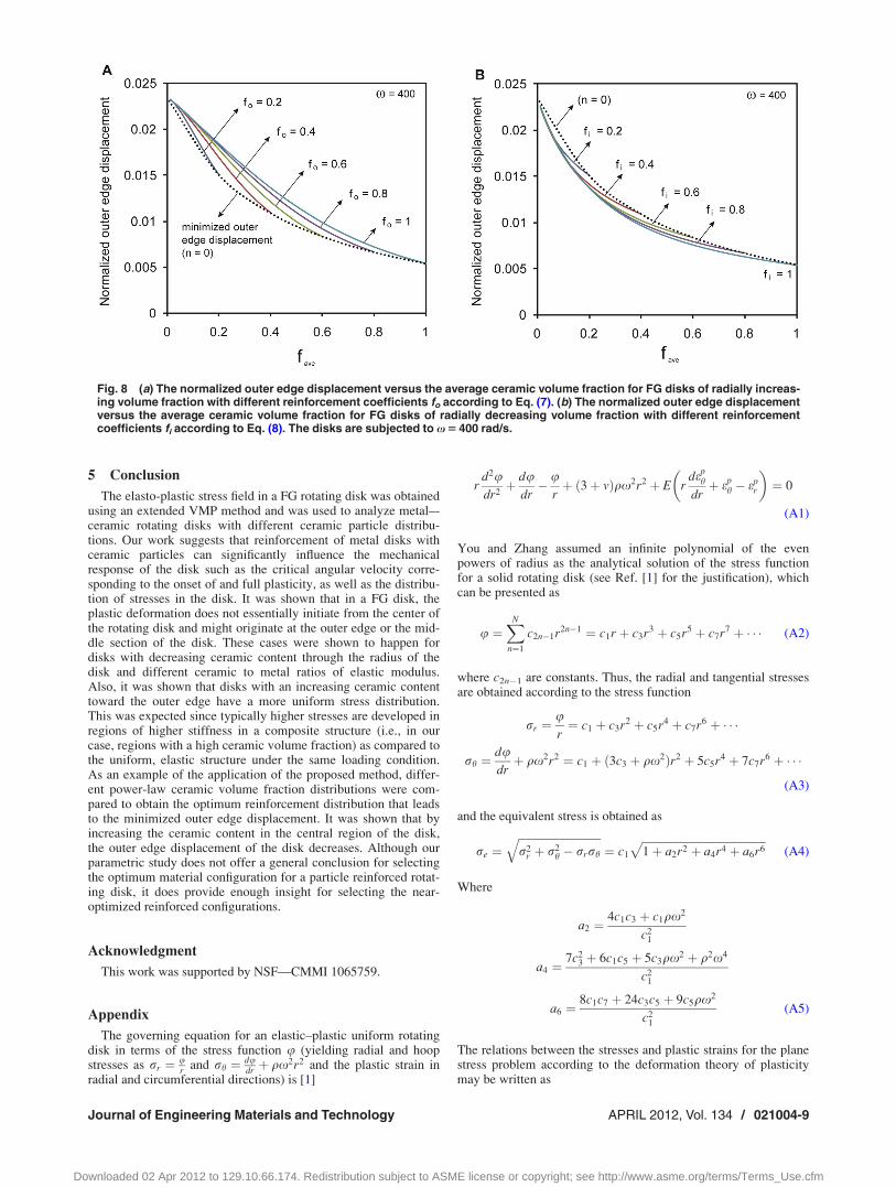
� fi.The disk outer edge displacement normalized by disk radius
versus the average volume fraction of ceramic constituent in adisk with x¼ 400 rad/s and different reinforcement distributioncoefficients fo is obtained and is shown in Fig. 8(a). The outeredge displacement is minimum when n¼ 0 in Eq. (7), implyingthat within disks with constant or increasing ceramic content inthe radial direction the uniform ceramic particle distributionyields the minimum radial plastic expansion. For disks withradially decreasing ceramic content according to Eq. (8) andx¼ 400 rad/s, the normalized outer edge displacement is plottedversus the average ceramic volume fraction in Fig. 8(b). In diskswith increasing ceramic content toward the center, whenever thevalue of ceramic average volume fraction is greater than 0.3 thedisk with fi¼ 1 yields the minimum outer edge displacement.When the average value is less than 0.3, the outer edge displace-ment in a disk with fi¼ fopt< 1 is minimum. However, the differ-ence between the displacements in disks with the fi¼ fi
opt andfi¼ 1 is relatively small.
Fig. 7 (a) Effect of relative stiffness of ceramic and metal, Ec/Em, on the distribution of von Mises stress in a FG rotating disksubjected to x 5 200 rad/s. (b) The von Mises stress distribution in a rotating disk with Ec/Em 5 0.1 subjected to four differentangular velocities. (c) The locus of elastic and plastic regions in a FG disk at different angular velocities for three values ofEc/Em. (d) Relative stiffness of ceramic and metal, Ec/Em, versus the angular velocities developing incipient and full plasticity ina FG disk. The ceramic volume fraction varies according to fc(r) 5 (1 2 r/R) in these sets of results.
021004-8 / Vol. 134, APRIL 2012 Transactions of the ASME
Downloaded 02 Apr 2012 to 129.10.66.174. Redistribution subject to ASME license or copyright; see http://www.asme.org/terms/Terms_Use.cfm
5 Conclusion
The elasto-plastic stress field in a FG rotating disk was obtainedusing an extended VMP method and was used to analyze metal–-ceramic rotating disks with different ceramic particle distribu-tions. Our work suggests that reinforcement of metal disks withceramic particles can significantly influence the mechanicalresponse of the disk such as the critical angular velocity corre-sponding to the onset of and full plasticity, as well as the distribu-tion of stresses in the disk. It was shown that in a FG disk, theplastic deformation does not essentially initiate from the center ofthe rotating disk and might originate at the outer edge or the mid-dle section of the disk. These cases were shown to happen fordisks with decreasing ceramic content through the radius of thedisk and different ceramic to metal ratios of elastic modulus.Also, it was shown that disks with an increasing ceramic contenttoward the outer edge have a more uniform stress distribution.This was expected since typically higher stresses are developed inregions of higher stiffness in a composite structure (i.e., in ourcase, regions with a high ceramic volume fraction) as compared tothe uniform, elastic structure under the same loading condition.As an example of the application of the proposed method, differ-ent power-law ceramic volume fraction distributions were com-pared to obtain the optimum reinforcement distribution that leadsto the minimized outer edge displacement. It was shown that byincreasing the ceramic content in the central region of the disk,the outer edge displacement of the disk decreases. Although ourparametric study does not offer a general conclusion for selectingthe optimum material configuration for a particle reinforced rotat-ing disk, it does provide enough insight for selecting the near-optimized reinforced configurations.
Acknowledgment
This work was supported by NSF—CMMI 1065759.
Appendix
The governing equation for an elastic–plastic uniform rotatingdisk in terms of the stress function u (yielding radial and hoopstresses as rr ¼ u
r and rh ¼ dudr þ qx2r2 and the plastic strain in
radial and circumferential directions) is [1]
rd2udr2þ du
dr� u
rþ ð3þ vÞqx2r2 þ E r
deph
drþ ep
h � epr
� �¼ 0
(A1)
You and Zhang assumed an infinite polynomial of the evenpowers of radius as the analytical solution of the stress functionfor a solid rotating disk (see Ref. [1] for the justification), whichcan be presented as
u ¼XN
n¼1
c2n�1r2n�1 ¼ c1r þ c3r3 þ c5r5 þ c7r7 þ � � � (A2)
where c2n�1 are constants. Thus, the radial and tangential stressesare obtained according to the stress function
rr ¼ur¼ c1 þ c3r2 þ c5r4 þ c7r6 þ � � �
rh ¼dudrþ qx2r2 ¼ c1 þ ð3c3 þ qx2Þr2 þ 5c5r4 þ 7c7r6 þ � � �
(A3)
and the equivalent stress is obtained as
re ¼ffiffiffiffiffiffiffiffiffiffiffiffiffiffiffiffiffiffiffiffiffiffiffiffiffiffiffiffiffiffir2
r þ r2h � rrrh
q¼ c1
ffiffiffiffiffiffiffiffiffiffiffiffiffiffiffiffiffiffiffiffiffiffiffiffiffiffiffiffiffiffiffiffiffiffiffiffiffiffiffiffiffiffiffiffiffi1þ a2r2 þ a4r4 þ a6r6
p(A4)
Where
a2 ¼4c1c3 þ c1qx2
c21
a4 ¼7c2
3 þ 6c1c5 þ 5c3qx2 þ q2x4
c21
a6 ¼8c1c7 þ 24c3c5 þ 9c5qx2
c21
(A5)
The relations between the stresses and plastic strains for the planestress problem according to the deformation theory of plasticitymay be written as
Fig. 8 (a) The normalized outer edge displacement versus the average ceramic volume fraction for FG disks of radially increas-ing volume fraction with different reinforcement coefficients fo according to Eq. (7). (b) The normalized outer edge displacementversus the average ceramic volume fraction for FG disks of radially decreasing volume fraction with different reinforcementcoefficients fi according to Eq. (8). The disks are subjected to x 5 400 rad/s.
Journal of Engineering Materials and Technology APRIL 2012, Vol. 134 / 021004-9
Downloaded 02 Apr 2012 to 129.10.66.174. Redistribution subject to ASME license or copyright; see http://www.asme.org/terms/Terms_Use.cfm
epr ¼
epe
rerr �
1
2rh
� �eph ¼
epe
rerh �
1
2rr
� �(A6)
The equivalent stress and plastic strain are assumed to have a lin-ear relation as ep
e ¼ a1re þ a0. Substitution into Eq. (A6) yields
epr ¼ a1 þ
a0
re
� �rr �
1
2rh
� �eph ¼ a1 þ
a0
re
� �rh �
1
2rr
� �(A7)
expressing the term 1re
in Eq. (A7) according to the even powers ofr using the Taylor series expansion yields
1
re¼ 1
c1
ð1þ b2r2 þ b4r4 þ b6r6Þ (A8)
where
b2 ¼ �a2
2
b4 ¼3
8a2
2 �a4
2
b6 ¼ �45
144a3
2 þ3
4a2a4 �
a6
2(A9)
The plastic strain components now may be written as the follow-ing polynomials
epr ¼ ep
r0 þ epr2r2 þ ep
r4r4 þ epr6r6 þ � � �
eph ¼ ep
h0 þ eph2r2 þ ep
h4r4 þ eph6r6 þ � � � (A10)
where epri, ep
hi (i¼ 0,2,4,6,...) in Eq. (A10) are obtained fromEqs. (A3), (A7), and (A8) as follows:
epr0 ¼ a1 þ
a0
c1
� �c1
2
epr2 ¼ a1 þ
a0
c1
� �� c3
2� qx2
2
� �þ a0b2
2
epr4 ¼ a1 þ
a0
c1
� �� 3c5
2
� �þ a0b2
c1
� �� c3
2� qx2
2
� �þ a0b4
2
epr6 ¼ a1 þ
a0
c1
� �� 5c7
2
� �þ a0b2
c1
� �� 3c5
2
� �
þ a0b4
c1
� �� c5
2� qx2
2
� �þ a0b6
2
eph0 ¼ a1 þ
a0
c1
� �c1
2
eph2 ¼ a1 þ
a0
c1
� �5c3
2þ qx2
� �þ a0b2
2
eph4 ¼ a1 þ
a0
c1
� �9c5
2
� �þ a0b2
c1
� �5c3
2þ qx2
� �þ a0b4
2
xph6 ¼ a1 þ
a0
c1
� �13c7
2
� �þ a0b2
c1
� �9c5
2
� �
þ a0b4
c1
� �5c3
2þ qx2
� �þ a0b6
2(A11)
Substituting Eqs. (A10) and (A2) into Eq. (A1) and combining theterms with the same power of r, results in the following equations:
eph0 � ep
r0 ¼ 0;
8c3 þ ð3þ vÞqx2 þ Eð3eph2 � ep
r2Þ ¼ 0;
24c5 þ Eð5eph4 � ep
r4Þ ¼ 0;
48c7 þ Eð7eph6 � ep
r6Þ ¼ 0; (A12)
The substitution of Eq. (A11) into (A12) gives the values of c3;c5, and c7 coefficients in terms of c1 (not presented here for thesake of brevity).
Fully Plastic Solid Disk. For the case of a fully plastic rotatingdisk, the boundary condition of the problem is rr ¼ 0 at r ¼ R.By substituting the values c3; c5, and c7 in terms of c1 intoEq. (A3) and satisfying the boundary conditions for c1, thestresses inside the rotating disk can be obtained according toEqs. (A3).
Elasto-Plastic Solid Disk. For the case of an elastic plasticrotating disk, let us assume that 1 is the radius of plastic region ofthe disk. Then, stresses in outer elastic region of the disk can beobtained according to 1 by solving the governing equations for anelastic rotating hollow disk considering the proper boundaryconditions
rer ¼ Ar�2 þ B� 3þ v
8qx2r2;
rer ¼ �Ar�2 þ B� 1þ 3v
8qx2r2; (A13)
rer ¼ 0 at r ¼ R;
reeq ¼ ryield and rh; rr > 0 at r ¼ 1 (A14)
For the inner plastic disk, there are only two unknown constantsc1 and 1, which can be determined by solving the proper boundaryconditions
rpr ¼ re
r at r ¼ 1;
rph ¼ re
h at r ¼ 1; (A15)
Finally, stresses inside the plastic and elastic regions can beobtained following Eqs. (A3) and (A13), respectively.
Using the proposed analytical method which is discussedbriefly above, we re-evaluated the case1 problem in Ref. [1] andobtained closer stresses to finite elements results compared tothose obtained by You and Zhang. For example, the stress at thecenter of the disk with the given linear hardening parameters(Eq. (27) in Ref. [1]) was obtained to be equal to 300.8 MPa byour analysis with 0.9% error from the finite element result(298 MPa), compared to the value of �335 MPa obtained by Youand Zhang which has an error equal to �12.5% compared to thefinite element analysis. The error in calculating the elastic–plasticstresses associated with the assumption of linearly hardening ma-terial is also reported in Ref. [3], which is erroneous according toour analysis and could be developed as a result of employed solu-tion method.
References[1] You, L. H., and Zhang, J. J., 1999, “Elastic-Plastic Stresses in a Rotating Solid
Disk,” Int. J. Mech. Sci., 41, pp. 269–282.[2] Guven, U., 1992, “Elastic-Plastic Stresses in a Rotating Annular Disk of Vari-
able Thickness and Variable Density,” Int. J. Mech. Sci., 34, pp. 133–138.[3] You, L. H., Tang, Y. Y., Zhang, J. J., and Zheng, C. Y., 2000, “Numerical Anal-
ysis of Elastic-Plastic Rotating Disks With Arbitrary Variable Thickness andDensity,” Int. J. Solids Struct., 37, pp. 7809–7820.
[4] Gamer, U., 1984, “Elastic-Plastic Deformation of the Rotating Solid Disk,”Arch. Appl. Mech., 54, pp. 345–354.
[5] Jahed, H., and Sherkati, S., 2000, “Thermoplastic Analysis of InhomogeneousRotating Disk With Variable Thickness,” International Conference Fatigue2000: Fatigue & Durability Assessment of Materials, Components and
021004-10 / Vol. 134, APRIL 2012 Transactions of the ASME
Downloaded 02 Apr 2012 to 129.10.66.174. Redistribution subject to ASME license or copyright; see http://www.asme.org/terms/Terms_Use.cfm
Structures, M. R. Bache, P. A. Blackmore, J. Draper, J. H. Edwards, P. Roberts,and J. R. Yates, eds., Cambridge, United Kingdom, pp. 229–238.
[6] Eraslan, A. N., and Orcan, Y., 2002, “Elastic-Plastic Deformation of a RotatingSolid Disk of Exponentially Varying Thickness,” Mech. Mater., 34, pp.423–432.
[7] Eraslan, A. N., and Orcan, Y., 2002, “On the Rotating Elastic-Plastic SolidDisks of Variable Thickness Having Concave Profiles,” Int. J. Mech. Sci., 44,pp. 1445–1466.
[8] Arslan, M. A., 2008, “Flywheel Geometry Design for Improved Energy StorageUsing Finite Element Analysis,” Mater. Des., 29, pp. 514–518.
[9] Bhavikatti, S. S., and Ramakrishnan, C. V., 1980, “Optimum Shape Design ofRotating Disks,” Comput. Struct., 11, pp. 397–401.
[10] Chern, J. M., and Prager, W., 1970, “Optimal Design of Rotating Disk forGiven Radial Displacement of Edge,” J. Optim. Theory Appl., 6, pp. 161–170.
[11] Danfelt, E. L., Hewes, S. A., and Chou, T.-W., 1977, “Optimization of Compos-ite Flywheel Design,” Int. J. Mech. Sci., 19, pp. 69–78.
[12] Eby, D., Averill, R., Gelfand, B., Punch, W., Mathews, O., and Goodman, E.,1997, “An Injection Island GA for Flywheel Design Optimization,” 5th Euro-pean Congress on Intelligent Techniques and Soft Computing EUFIT ’97, A.Verlag Mainz, ed., Morgan Kaufmann, Aachen, Germany, pp. 687–691.
[13] Krack, M., Secanell, M., and Mertiny, P., 2010, “Cost Optimization of HybridComposite Flywheel Rotors for Energy Storage,” Struct. Multidiscip. Optim.,41, pp. 779–795.
[14] Huang, J., and Fadel, G. M., 2000, “Heterogeneous Flywheel Modeling andOptimization,” Mater. Des., 21, pp. 111–125.
[15] Stump, F. V., Paulino, G. H., and Silva, C. N., 2005, “Material DistributionDesign of Functionally Graded Rotating Disks With Stress Constraint,” 6thWorld Congresses of Structural and Multidisciplinary Optimization, Rio deJaneiro, Brazil.
[16] Stump, F. V., Silva, E. C. N., and Paulino, G. H., 2007, “Optimization of Mate-rial Distribution in Functionally Graded Structures With Stress Constraints,”Commun. Numer. Methods Eng., 23, pp. 535–551.
[17] Funabashi, M., 1997, “Gradient Composites of Nickel Coated Carbon FibreFilled Epoxy Resin Moulded Under Centrifugal Force,” Composites, Part A,28, pp. 731–737.
[18] Hashmi, S., and Dwivedi, U., 2007, “Estimation of Concentration of Particlesin Polymerizing Fluid During Centrifugal Casting of Functionally Graded Poly-mer Composites,” J. Polym. Res., 14, pp. 75–81.
[19] Watanabe, Y., Eryu, H., and Matsuura, K., 2001, “Evaluation of Three-Dimensional Orientation of Al3Ti Platelet in Al-Based Functionally GradedMaterials Fabricated by a Centrifugal Casting Technique,” Acta Mater., 49, pp.775–783.
[20] Xie, Y., Liu, C., Zhai, Y., Wang, K., and Ling, X., 2009, “Centrifugal CastingProcesses of Manufacturing In Situ Functionally Gradient Composite Materialsof Al-19Si-5Mg Alloy,” Rare Met., 28, pp. 405–411.
[21] Bayat, M., Sahari, B. B., Saleem, M., Ali, A., and Wong, S. V., 2009, “BendingAnalysis of a Functionally Graded Rotating Disk Based on the First OrderShear Deformation Theory,” Appl. Math. Model., 33, pp. 4215–4230.
[22] Fazelzadeh, S. A., Malekzadeh, P., Zahedinejad, P., and Hosseini, M., 2007,“Vibration Analysis of Functionally Graded Thin-Walled Rotating BladesUnder High Temperature Supersonic Flow Using the Differential QuadratureMethod,” J. Sound Vib., 306, pp. 333–348.
[23] Guven, U., celik, A., and Baykara, C., 2004, “On Transverse Vibrations ofFunctionally Graded Polar Orthotropic Rotating Solid Disk With VariableThickness and Constant Radial Stress,” J. Reinf. Plast. Compos., 23, pp.1279–1284.
[24] Librescu, L., Oh, S.-Y., and Song, O., 2005, “Thin-Walled Beams Made ofFunctionally Graded Materials and Operating in a High Temperature Environ-ment: Vibration and Stability,” J. Therm. Stresses, 28, pp. 649–712.
[25] Librescu, L., Oh, S.-Y., and Song, O., 2004, “Spinning Thin-Walled BeamsMade of Functionally Graded Materials: Modeling, Vibration and Instability,”Eur. J. Mech. A/Solids, 23, pp. 499–515.
[26] Oh, S.-Y., Librescu, L., and Song, O., 2005, “Vibration and Instability of Func-tionally Graded Circular Cylindrical Spinning Thin-Walled Beams,” J. SoundVib., 285, pp. 1071–1091.
[27] Eraslan, A., and Akis, T., 2006, “On the Plane Strain and Plane Stress Solutionsof Functionally Graded Rotating Solid Shaft and Solid Disk Problems,” ActaMech., 181, pp. 43–63.
[28] Bayat, M., Saleem, M., Sahari, B. B., Hamouda, A. M. S., and Mahdi, E., 2008,“Analysis of Functionally Graded Rotating Disks With Variable Thickness,”Mech. Res. Commun., 35, pp. 283–309.
[29] Durodola, J. F., and Attia, O., 2000, “Deformation and Stresses in FunctionallyGraded Rotating Disks,” Compos. Sci. Technol., 60, pp. 987–995.
[30] Horgan, C. O., and Chan, A. M., 1999, “The Stress Response of FunctionallyGraded Isotropic Linearly Elastic Rotating Disks,” J. Elast., 55, pp. 219–230.
[31] Kordkheili, S. A. H., and Naghdabadi, R., 2007, “Thermoelastic Analysis of aFunctionally Graded Rotating Disk,” Compos. Struct., 79, pp. 508–516.
[32] Haghpanah Jahromi, B., Farrahi, G. H., Maleki, M., Nayeb-Hashemi, H., andVaziri, A., 2009, “Residual Stresses in Autofrettaged Vessel Made of Function-ally Graded Material,” Eng. Struct., 31, pp. 2930–2935.
[33] Jahed, H., and Dubey, R. N., 1997, “An Axisymmetric Method of Elastic-Plastic Analysis Capable of Predicting Residual Stress Field,” ASME J. Pres-sure Vessel Technol., 119, pp. 264–273.
[34] Timoshenko, S. P., and Goodier, J. N., 1970, Theory of Elasticity, 3rd ed.,McGraw-Hill, New York.
[35] Budiansky, B., 1965, “On the Elastic Moduli of Some Heterogeneous Materi-als,” J. Mech. Phys. Solids, 13, pp. 223–227.
[36] Chaboche, J. L., Kanoute, P., and Roos, A., 2005, “On the Capabilities ofMean-Field Approaches for the Description of Plasticity in Metal MatrixComposites,” Int. J. Plast., 21, pp. 1409–1434.
[37] Hill, R., 1965, “A Self-Consistent Mechanics of Composite Materials,”J. Mech. Phys. Solids, 13, pp. 213–222.
[38] Love, B. M., and Batra, R. C., 2006, “Determination of Effective Thermome-chanical Parameters of a Mixture of Two Elastothermoviscoplastic Constitu-ents,” Int. J. Plast., 22, pp. 1026–1061.
[39] Mori, T., and Tanaka, K., 1973, “Average Stress in Matrix and Average ElasticEnergy of Materials With Misfitting Inclusions,” Acta Metall., 21, pp. 571–574.
[40] Saraev, D., and Schmauder, S., 2003, “Finite Element Modelling of Al/SiCpMetal Matrix Composites With Particles Aligned in Stripes—A 2D-3DComparison,” Int. J. Plast., 19, pp. 733–747.
[41] Vena, P., Gastaldi, D., and Contro, R., 2008, “Determination of the EffectiveElastic-Plastic Response of Metal-Ceramic Composites,” Int. J. Plast., 24, pp.483–508.
[42] Bao, G., Hutchinson, J. W., and McMeeking, R. M., 1991, “Particle Reinforce-ment of Ductile Matrices Against Plastic Flow and Creep,” Acta Metall. Mater.,39, pp. 1871–1882.
[43] Branch, N. A., Arakere, N. K., Subhash, G., and Klecka, M. A., 2011,“Determination of Constitutive Response of Plastically Graded Materials,” Int.J. Plast., 27, pp. 728–738.
[44] Grujicic, M., and Zhang, Y., 1998, “Determination of Effective Elastic Proper-ties of Functionally Graded Materials Using Voronoi Cell Finite Element Meth-od,” Mater. Sci. Eng. A, 251, pp. 64–76.
[45] Ju, J., and Chen, T., 1994, “Micromechanics and Effective Moduli of ElasticComposites Containing Randomly Dispersed Ellipsoidal Inhomogeneities,”Acta Mech., 103, pp. 103–121.
[46] Yin, H. M., Paulino, G. H., Buttlar, W. G., and Sun, L. Z., 2007,“Micromechanics-Based Thermoelastic Model for Functionally Graded Particu-late Materials With Particle Interactions,” J. Mech. Phys. Solids, 55, pp.132–160.
[47] Yin, H. M., Sun, L. Z., and Paulino, G. H., 2004, “Micromechanics-Based Elas-tic Model for Functionally Graded Materials With Particle Interactions,” ActaMater., 52, pp. 3535–3543.
[48] Yin, H. M., Sun, L. Z., and Paulino, G. H., 2005, “A Multiscale Framework forElastic Deformation of Functionally Graded Composites,” Mater. Sci. Forum,492–493, pp. 391–396.
[49] Suresh, S., and Mortensen, A., 1998, Fundamentals of Functionally GradedMaterials, IOM Communications Ltd., London.
[50] Gu, Y., Nakamura, T., Prchlik, L., Sampath, S., and Wallace, J., 2003, “Micro-Indentation and Inverse Analysis to Characterize Elastic-Plastic Graded Materi-als,” Mater. Sci. Eng. A, 345, pp. 223–233.
Journal of Engineering Materials and Technology APRIL 2012, Vol. 134 / 021004-11
Downloaded 02 Apr 2012 to 129.10.66.174. Redistribution subject to ASME license or copyright; see http://www.asme.org/terms/Terms_Use.cfm