elastohydrodynamic lubrication and finite configuration changes in reciprocating elastomeric seals
TRANSCRIPT
ARTICLE IN PRESS
Tribology International 42 (2009) 615–627
Contents lists available at ScienceDirect
Tribology International
0301-67
doi:10.1
� Corr
E-m
journal homepage: www.elsevier.com/locate/triboint
Elastohydrodynamic lubrication and finite configuration changes inreciprocating elastomeric seals
Stanis"aw Stupkiewicz �, Artur Marciniszyn
Institute of Fundamental Technological Research (IPPT), Swietokrzyska 21, 00–049 Warsaw, Poland
a r t i c l e i n f o
Article history:
Received 23 April 2008
Received in revised form
20 August 2008
Accepted 27 August 2008Available online 11 October 2008
Keywords:
Elastohydrodynamic lubrication
Hyperelastic model
Dynamic sealing
9X/$ - see front matter & 2008 Elsevier Ltd. A
016/j.triboint.2008.08.008
esponding author.
ail address: [email protected] (S. Stupkiew
a b s t r a c t
A computational framework has been developed for a fully coupled analysis of elastohydrodynamic
lubrication and finite deformations of elastomeric reciprocating seals in hydraulic actuators. The
relevant formulation is provided, which consistently treats finite configuration changes of the seal
modelled as a hyperelastic (Mooney-Rivlin) solid. The steady-state hydrodynamic lubrication is
modelled using the classical Reynolds equation. Coupling of the solid and fluid parts is fully accounted
for, including friction due to shear stresses in the lubricant film. Detailed results of finite element
simulations are provided for two benchmark problems of O-ring and rectangular rod seals in a wide
range of process parameters.
& 2008 Elsevier Ltd. All rights reserved.
1. Introduction
Hydrodynamic lubrication in reciprocating hydraulic seals is aclassical topic studied experimentally and theoretically for morethan 50 years now, cf. Nau [1]. It is thus rather surprising thatdetailed solutions of the corresponding elastohydrodynamiclubrication problems are not easily found in the literature,particularly in view of the substantial progress in computationaltechniques and increase of computer power observed in the lastdecades. This paper aims at filling this gap by providing therelevant formulation, which consistently treats finite configura-tion changes, along with a computational scheme and detailedresults of numerical simulations.
Compared to the more classical hard EHL problems [2], in thesoft EHL problems of elastomeric seals, the lubricant pressures arerelatively low so that effects such as variation of viscosity withpressure and compressibility of the fluid are not essential. At thesame time, in the case of hard EHL problems, the maximumpressure is typically two orders of magnitude smaller than theelastic modulus and thus the linear elasticity is an appropriatemodel for contacting members. This is not the case of elastomericseals which are characterized by a very low elastic stiffness sothat the lubricant pressures may easily exceed the shear modulusby one order of magnitude. Accordingly, finite deformationswith finite configuration changes are expected to occur, at least
ll rights reserved.
icz).
locally, and these require appropriate theoretical and numericaltreatment.
Simulation of the hydrodynamic lubrication in the seal–rodsystem requires determination of the flow of the lubricant(hydraulic fluid) in the thin film between the seal and the rodand, in parallel, determination of the deformation of the seal.Clearly, the two phenomena are coupled, and several availablesolution methods differ in the way in which this coupling istreated.
The inverse hydrodynamic theory (cf. [3]) is based on theassumption that the contact pressure is not affected bythe lubricating film developing between the seal and the rod(as the film thickness is much smaller than the elastic deflectionsof the seal). Accordingly, the distribution of the contact pressure,obtained from a purely mechanical contact analysis, is used toestimate the film thickness in characteristic points along thecontact interface. Here, and in all the other relevant models, thefluid part is conveniently described by the Reynolds equation.
In the elastohydrodynamic lubrication problem, the elasticdeflections of the seal are solved simultaneously with theReynolds equation. In the early works, the linear elasticitytogether with the finite element method were used for thatpurpose, typically combined with the static condensation, cf.Ruskell [4], Yang and Hughes [5]. Prati and Strozzi [6] developed amodel based on the finite-deformation theory with a hyperelasticmaterial model adopted for the seal. The corresponding finiteelement model was used to compute the contact pressures whilethe (linear) influence coefficient matrix obtained through thenodal perturbation technique was used in the EHL analysis.Influence coefficients were also used by Salant et al. [7].
ARTICLE IN PRESS
Fig. 1. Rod seal: initial (reference) and deformed configurations.
S. Stupkiewicz, A. Marciniszyn / Tribology International 42 (2009) 615–627616
Simplified analytical models have been developed for rectan-gular seals, which have particularly simple geometry, cf. Field andNau [8]. Similar approach has been used in a recent model ofNikas [9] which has also been extended to account for nonlinearelasticity of elastomeric seals, cf. Nikas and Sayles [10]. However,these simplified models are not able to represent some features ofthe solution, for instance, the pressure peaks at the roundedcorners which were observed experimentally and also werepredicted numerically by Prati and Strozzi [6], see also Section 4.2.
In the present approach, the nonlinearities associated withthe finite configuration changes and hyperelasticity of the seal arefully accounted for. The focus of this work is on the coupling of thehydrodynamic lubrication and finite deformations of the seal.Accordingly, several effects, such as the influence of surfaceroughness (e.g. [7,9]) and extrusion of the seal at the air side,which are known to be important in some situations, are notaddressed here. Also, to fix the attention, the rod seals are onlyreferred to throughout the paper, although, the approach isobviously more general.
The formulation of the corresponding EHL problem is introducedin Section 2 and the finite element discretization along with theadopted solution strategy are discussed in Section 3. As anapplication, the analysis of the steady-state hydrodynamic lubrica-tion and dynamic sealing performance of reciprocating O-ring andrectangular seals is carried out in Section 4. Due to the simplegeometry, these two types of seals are particularly suitable forbenchmark and verification examples. Based on the study ofconvergence of the solution with mesh refinement, relatively finediscretization has been used for the computations. Accordingly, finefeatures of the solutions could be captured, such as sharp minimaand maxima of the film thickness and pressure at the outlet and inletzones. Results of similar scope could not be found in the literature.
2. Problem formulation
2.1. Finite deformations of hyperelastic seal
The present model of the seal–rod system accounts for thedeformations of the seal due to the action of the hydrostaticsealed pressure as well as contact interactions with the housingand with the rod, the latter in the hydrodynamic lubricationregime. The housing and the rod are assumed rigid, while theelastomeric seal will typically undergo finite deformations, atleast locally. Accordingly, two configurations are introduced, thestress-free initial (reference) configuration O and the deformedconfiguration o, as illustrated in Fig. 1. The boundary qO isdivided1 into three parts qlO, qpO and qcO associated with thehydrodynamic lubrication, hydrostatic sealed pressure and con-tact interaction with the housing, respectively. The deformed-configuration counterparts are qlo, qpo and qco, cf. Fig. 1.
The deformation from O to o is described by a continuousmapping x ¼ uðXÞ, where X 2 O and x 2 o, and the deformationgradient F ¼ Gradu is the basic strain-like variable. In theabsence of body and inertia forces, the weak form of theequilibrium equation is given byZO
P � GraddudV �
ZqO
T � du dS ¼ 0, (1)
1 There is no exact criterion for the transition from hydrostatic pressure
loading on qpO to hydrodynamic conditions on qlO. However, in practice, the
transition point can be chosen arbitrarily provided that the film thickness at this
point is much higher than the thickness in the actual lubrication zone (see also the
discussion following Eqs. (17) and (18) in the next subsection). Similar argument
applies for the boundary between qlO and qcO at the air side.
where P is the first Piola–Kirchhoff stress tensor and T isthe nominal traction vector prescribed on the boundary qO (thenominal traction is referred to the unit area in the referenceconfiguration).
The constitutive law of a hyperelastic material is fully definedby the elastic strain energy function WðFÞ, namely
P ¼qW
qF. (2)
In this work, the Mooney-Rivlin material model is used, forwhich the strain energy function can be written as
WðFÞ ¼ 12m1ðI1 � 3Þ þ 1
2m2ðI2 � 3Þ þWvðI3Þ, (3)
where I1, I2 and I3 are the invariants of the left Cauchy–Greendeformation tensor B,
I1 ¼ tr B; I2 ¼12ðI
21 � tr B
2Þ; I3 ¼ det B (4)
and
B ¼ FFT; B ¼ I�1=33 B. (5)
Here m1 and m2 are material parameters such that m ¼ m1 þ m2 isthe shear modulus in the initial configuration. With k denotingthe bulk modulus, the volumetric part WvðI3Þ is given by
WvðI3Þ ¼12kð
12ðI3 � 1Þ � 1
2 log I3Þ. (6)
The surface traction term in Eq. (1) can be equivalentlyevaluated in the deformed configuration, namelyZqO
T � du dS ¼
Zqo
t � duds, (7)
where t is the spatial traction vector, i.e. one referred to the unitarea in the deformed configuration. The later form is moreconvenient in the case of the hydrostatic and hydrodynamicpressure loading. The integrals in Eq. (7) are thus split into threeparts corresponding to qpo, qlo and qco. On qpo, the spatialtraction is given by
t ¼ �psn on qpo, (8)
where ps is the sealed pressure and n is the unit vector normal tothe surface in the deformed configuration and pointing outward.The loading from the hydrodynamic pressure along the lubricatedboundary qlo is treated analogously, as discussed in more detailin Section 2.2.
Finally, the contribution from unilateral frictionless contactwith the housing along the contact boundary qco is introduced ina standard manner using Lagrange multipliers (e.g. [11]), so thatZqco
t � duds ¼
Zqco
lNdgN ds, (9)
where the Lagrange multipliers lN and the normal gap gN (definedsuch that gN40 in case of separation) satisfy the Signorinicondition,
gNX0; lNp0; gNlN ¼ 0 on qco. (10)

ARTICLE IN PRESS
Fig. 2. Discretization of the lubricated boundary qlo into segments with linear
interpolation of displacements (mh ¼ 1) and higher-order interpolation of
lubricant pressure. The figure corresponds to mp ¼ 3 so that there are mp þ 1 ¼
4 pressure nodes per element.
Table 1O-ring seal: geometrical, material and process parameters
Inner diameter of the seal Dinner 50.39 mm
Diameter of the seal (cross-section) Dseal 3.53 mm
Rod diameter Drod 50.00 mm
Inner diameter of the housing Dhous 56.30 mm
Elastic parameters of the seal m1 3.04 MPa
m2 0.62 MPa
k 500 MPa
Oil viscosity (HLP 46) at 30 �C Z0 6:59� 10�8 MPa s
Pressure–viscosity coefficient a 0.021/MPa
Cavitation penalty parameter � 104 mm/(MPa s)
Rod speed U �2521600 mm/s
Sealed pressure ps 0–5 MPa
Table 2O-ring seal: number of elements and unknowns of the finite element mesh
No. of solid
elements
No. of
segments
for Reynolds
equation
Total no. of
unknowns
(mp ¼ 4)
No. of
pressure
unknowns
(mp ¼ 4)
Mesh density 1 420 27 1076 109
Mesh density 2 1560 54 3587 217
Mesh density 4 6000 108 12 929 433
Mesh density 8 23 520 216 48 893 865
Mesh density 16 93120 432 189 941 1729
S. Stupkiewicz, A. Marciniszyn / Tribology International 42 (2009) 615–627 617
In our implementation, the unilateral contact conditions (10)are regularized using the augmented Lagrangian technique,cf. Alart and Curnier [12], but other approaches could also beused. Details of the treatment of the unilateral contact interac-tions are not discussed here.
2.2. Reynolds equation
The flow of the lubricant (hydraulic fluid) in the thin gapbetween two solids in relative motion can be described by thewell-known Reynolds equation, cf. Dowson and Higginson [2],Muller and Nau [3]. The basic assumption of the Reynoldsequation is that the lubricant film thickness is small comparedto the other dimensions of the domain. It is thus formulated onthe nominal contact surface, which is assumed to approximatelycoincide with the two contacting surfaces. As in our case theelastomeric seal undergoes finite configuration changes, it mustbe explicitly stated that the Reynolds equation and all thequantities involved refer to the lubricated boundary qlo in thedeformed configuration.
Let us thus introduce the nominal contact surface g as thedomain in which the Reynolds equation holds. To fix the attention,g can be identified with the projection of the deformed boundaryqlo onto the rigid surface of the rod. For incompressible fluid, theReynolds equation can now be written in the form
divg qþqh
qt¼ 0; q ¼ uh�
h3
12Zgradg p, (11)
where p is the pressure, h the film thickness, q the lubricant flux, uthe average velocity of the contacting surfaces, and Z the viscosity.These quantities are defined on the domain g, hence the subscriptin the operators denoting the divergence and gradient within g.The dependence of viscosity on pressure is accounted for byadopting the classical Barus equation,
Z ¼ Z0 expðapÞ, (12)
where a is the pressure–viscosity coefficient and Z0 is theviscosity at zero pressure.
The essential and the natural boundary conditions are enforcedon the parts of the boundary of g, respectively, qpg and qqg.Denoting the prescribed pressure by p� and the prescribed flux byq�n we have
p ¼ p� on qpg; q � ng ¼ q�n on qqg. (13)
The weak form of the Reynolds equation, which constitutes thebasis of the finite element formulation, is obtained in a standardmanner by multiplying Eq. (11) by the test function dp, whichvanishes on qpg, and integrating over the domain g. Application ofthe Gauss theorem leads to the following weak form:Zg
gradg dp � q� dpqh
qt
� �dg�
Zqqg
dpq�n dl ¼ 0. (14)
In the case considered in this work, the Reynolds equationsimplifies significantly. Firstly, the axial symmetry is assumed inthe examples, so that the Reynolds equation becomes one-dimensional with, say, x as the only spatial variable involved(here x is a local coordinate which parameterizes g). Secondly, insteady-state conditions, the term qh=qt vanishes. Finally, only theessential boundary conditions are considered, namely conditionspðx�Þ ¼ ps and pðxþÞ ¼ 0 are enforced on the sealed-pressure sideand on the air side, respectively. The corresponding one-dimen-sional weak form reads
Z xþ
x�
ddp
dxuh�
h3
12Zdp
dx
!dx ¼ 0, (15)
where u ¼ U=2 and U is the rod speed (positive for outstroke, asindicated in Fig. 1).
In order to avoid a non-physical pressure drop below zero inthe outlet zone, the cavitation condition pX0 is approximatelyenforced using the penalty method, cf. Wu [13]. The correspond-ing weak form becomes then
Z xþ
x�
ddp
dxuh�
h3
12Zdp
dx
!þ �dpmaxð�p;0Þ
" #dx ¼ 0, (16)
where �40 is a cavitation penalty parameter. The penalty termhas no effect in the region of positive pressure and, at the sametime, it penalizes the negative pressures which tend to zero forsufficiently large �. This approach is simple and straightforward inimplementation and proves sufficient for the range of problemsaddressed in this work.
The coupling of the Reynolds equation (16) and the equilibriumequation (1) is through the dependence of the film thickness h onthe deformation of the seal and, secondly, through the forcesexerted by the fluid on the seal boundary qlo. The correspondingsurface traction is given by
t ¼ �pnþ ts on qlo, (17)

ARTICLE IN PRESS
Fig. 4. O-ring seal in deformed configuration: finite element mesh (mesh density 2) for sealed pressure (a) ps ¼ 0, (b) ps ¼ 1 MPa and (c) ps ¼ 5 MPa. The contact surfaces of
the rod and the housing are indicated by solid lines.
Fig. 3. O-ring seal in undeformed configuration: finite element mesh for (a) mesh density 1, (b) mesh density 2 and (c) mesh density 4. The contact surfaces of the rod and
the housing are indicated by solid lines. The rod is on the top and the sealed-pressure side is on the left.
S. Stupkiewicz, A. Marciniszyn / Tribology International 42 (2009) 615–627618
where the first term is due to the hydrodynamic pressure p andthe second term is due to the shear stress2 t,
t ¼ ZU
h�
h
2
dp
dx, (18)
which follows from the parabolic velocity profile across the film asassumed by the Reynolds equation. The unit vector s in Eq. (17) isconstant and tangent to the nominal surface g. At the same time,the hydrodynamic pressure loading is assumed to follow thecurrent normal to the deformed surface. Accordingly, the hydro-static and hydrodynamic pressure loading along, respectively, qpoand qlo, are treated consistently.
As already mentioned in the previous subsection, there is quitesome freedom in choosing the point of transition from hydrostaticto hydrodynamic conditions (i.e. the boundary between qpo andqlo at the sealed-pressure side and between qco and qlo at theair side). This is because of the second term in expression (11)2
defining the lubricant flux, which is cubic in h. Thus, as the filmthickness h increases in the inlet and outlet zones, the pressuregradient quickly converges to zero. Accordingly, the position atwhich the essential boundary condition (13)1 is enforced has a
2 Note that the effect of friction on the deformation of the contacting bodies is
usually assumed negligible in EHL problems. This assumption is only partially
justified in the present case of elastometric seals (soft EHL problems), as illustrated
by the numerical examples in Section 4.
negligible effect on the solution of the Reynolds equation,provided that this point is sufficiently far from the actualhydrodynamic lubrication region (i.e. region of small film thick-ness). In practice, this requires that an initial contact analysis isperformed in order to determine a suitable position of thetransition point.
3. Numerical treatment
3.1. Finite element discretization
The finite element method is used to solve the elastohydrody-namic lubrication problem defined in the previous section. Recallthat the problem is specified by the mechanical equilibriumequation (the solid part) and the Reynolds equation (lubrication),expressed by the respective variational weak forms (1) and (14).The virtual work of surface tractions, i.e. the second term inEq. (1), is further split into three parts corresponding to thehydrostatic pressure on qpo, contact with the housing on qco, andhydrodynamic lubrication on qlo.
The finite element formulation is obtained in a standardmanner (e.g. Zienkiewicz and Taylor [14]). The finite elementapproximations of the unknown displacement and pressure fieldsare introduced, followed by element-wise numerical integrationof the respective contributions. This leads to the set of nonlinear

ARTICLE IN PRESS
ps = 5 MPaps = 3 MPaps = 1 MPaps = 0 MPa
U =100 mm/s
U =100 mm/s
0
2
4
6
8
ps = 5 MPaps = 3 MPaps = 1 MPa
Pres
sure
[M
Pa]
Film
thic
knes
s [�
m]
Pres
sure
[M
Pa]
Film
thic
knes
s [�
m]
−0.5 0.0 0.5 1.0 1.5
0
2
4
6
8
Position [mm]
−0.5 0.0 0.5 1.0 1.5
Position [mm]
Fig. 6. O-ring seal: pressure profile (a,c) and film thickness (b,d) during
mp=1mp=2mp=3mp=4mp=5
1 2 4 8 16
0.4
0.6
0.8
1.0
1.2
Mesh density
Film
thic
knes
s h* [
�m]
Fig. 5. O-ring seal: convergence of the leakage rate represented by h� ¼ q=u with
mesh refinement (outstroke, ps ¼ 1 MPa, U ¼ 400 mm=s).
S. Stupkiewicz, A. Marciniszyn / Tribology International 42 (2009) 615–627 619
equations for unknown nodal displacements, pressures andLagrange multipliers, the later enforcing the unilateral contactconditions. The only non-standard part in this procedure is thetreatment of the Reynolds equation and this is commented inmore detail below. The case of axial symmetry is only consideredso that the solid part is analyzed in two-dimensions and theReynolds equation is one-dimensional.
It is generally accepted that finite deformations, particularly inthe case of nearly incompressible materials, are most efficientlyresolved using low-order elements which, however, requirespecial treatment of shear and volumetric locking effects usingtechniques such as enhanced assumed strain or mixed formula-tions, reduced integration, and others. In this work, an under-integrated axisymmetric four-node element is used whichemploys volumetric–deviatoric split and Taylor expansion ofshape functions [15].
Importantly, the use of low-order solid elements implies thatthe boundary is discretized into line segments with piecewise-linear interpolation of displacements. The surface traction termsin the weak form (1) are evaluated along these segments. Considerthus the lubricated boundary qlO discretized into finite elements,each formed by a line segment with two displacement nodes.In the deformed configuration, the position of a typical element,cf. Fig. 2, is specified by the current positions xel
1 and xel2 of the two
nodes. Projection of all the elements of the discretized deformed
ps = 5 MPaps = 3 MPaps = 1 MPaps = 0 MPa
ps = 5 MPaps = 3 MPaps = 1 MPa
U =100 mm/s0.4
0.5
0.6
0.7
0.8
Position [mm]
U =100 mm/s
−0.5 0.0 0.5 1.0 1.5
Position [mm]
−0.5 0.0 0.5 1.0 1.5
0.2
0.3
0.4
0.5
0.6
outstroke (a,b) and instroke (c,d) at the rod speed U ¼ 100 mm=s.
ARTICLE IN PRESS
U = 400 mm/s
U = 200 mm/s
U = 100 mm/s
U = 50 mm/s
0 1 2 3 4 5
0.0
0.5
1.0
1.5
Sealed pressure, ps [MPa]Fi
lm th
ickn
ess,
h∗ [
�m]
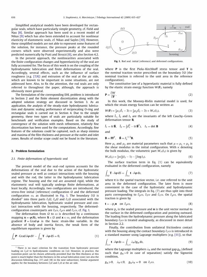
Fig. 8. O-ring seal: parameter h� ¼ q=u as a function of the sealed pressure ps
(instroke—solid lines, outstroke—dashed lines).
S. Stupkiewicz, A. Marciniszyn / Tribology International 42 (2009) 615–627620
surface qlo onto the nominal contact surface g defines thediscretization of the domain g into finite elements used to solvethe Reynolds equation, cf. Fig. 2.
The Reynolds equation involves two fields, namely thepressure p (the basic unknown) and the film thickness h. Linearinterpolation of the displacements implies linear interpolation ofthe film thickness (first-order interpolation, mh ¼ 1). However,arbitrary interpolation order can be adopted for the pressure.Interpolation orders ranging from mp ¼ 1 (linear interpolation) tomp ¼ 5 have been tested and it turns out that higher-orderinterpolations have a positive effect on the accuracy and stabilityof the method, with a relatively small overhead on the totalnumber of unknowns and on the overall computational cost.Detailed results concerning convergence of the method with meshrefinement and pressure interpolation order will be reportedelsewhere (selected results are provided in Section 4). Based onthese studies interpolation order mp ¼ 4 has been chosen andused to study the dynamic sealing performance of O-ring andrectangular seals in Section 4.
The convergence studies revealed also spurious oscillations ofpressure and film thickness which occur in severe lubricationconditions, typically at lower rod speeds and at higher sealedpressures. It has been observed that these oscillations are reducedby increasing the mesh density and, with a much weaker effect, byincreasing the interpolation order of the pressure. Application ofthe discontinuous Galerkin method (which appears to be efficient
outstrokeinstroke
ps = 3 MPa, U = 100 mm/s ps = 3 MPa, U = 100 mm/s
ps = 3 MPa, U = 100 mm/sps = 3 MPa, U = 100 mm/s
−0.5 0.0 0.5 1.0 1.5
0
1
2
3
4
5
6
outstrokeinstroke
−0.5 0.0 0.5 1.0 1.5
0.0
0.2
0.4
0.6
0.8
outstrokeinstroke
−0.5 −0.4 1.1 1.2
0
1
2
3
4
5
outstrokeinstroke
−0.5 −0.4 1.1 1.2
0.2
0.3
0.4
0.5
0.6
0.7
0.8
Pres
sure
[M
Pa]
Pres
sure
[M
Pa]
Film
thic
knes
s [�
m]
Film
thic
knes
s [�
m]
Position [mm] Position [mm]
Position [mm] Position [mm]
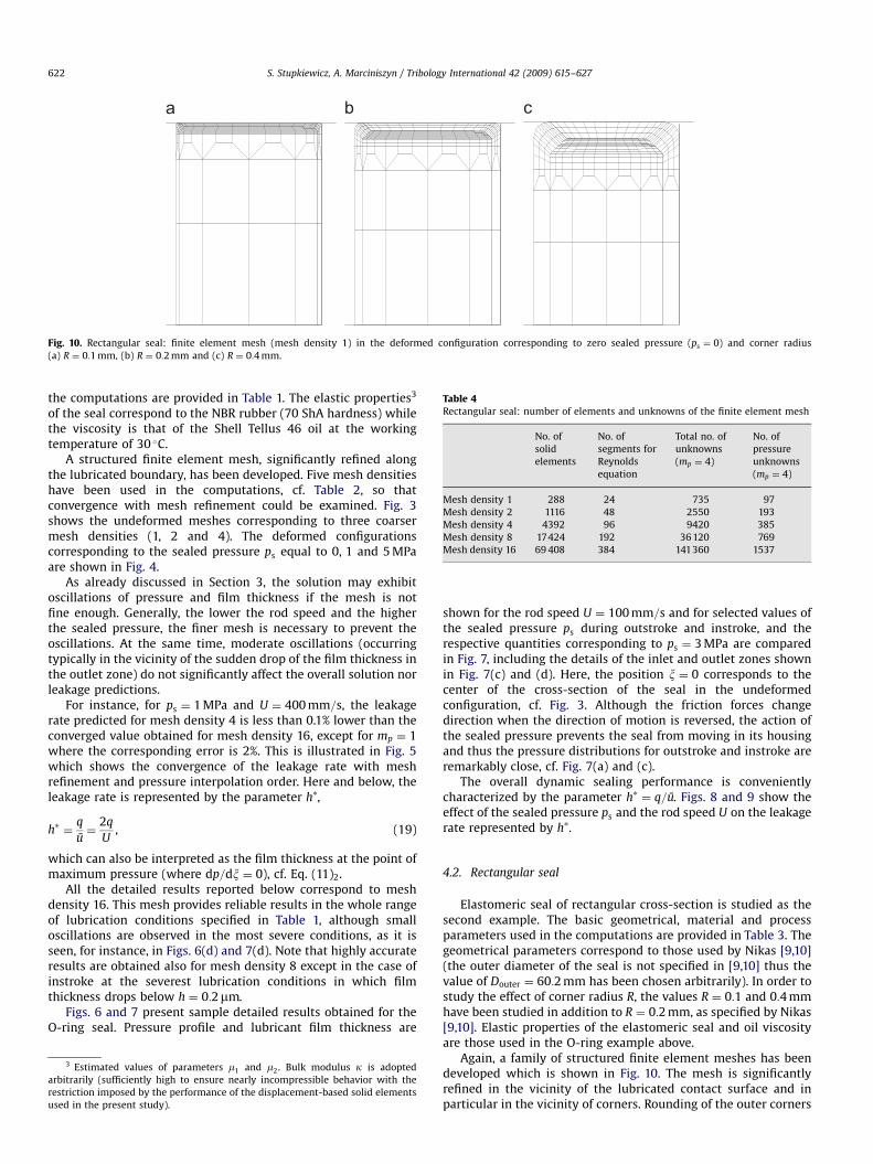
Fig. 7. O-ring seal: pressure profile (a,c) and film thickness (b,d) during outstroke and instroke for the sealed pressure ps ¼ 3 MPa and the rod speed U ¼ 100 mm=s.

ARTICLE IN PRESS
S. Stupkiewicz, A. Marciniszyn / Tribology International 42 (2009) 615–627 621
in the case of the classical hard EHL line contact problems, cf. [16])does not help significantly.
Computer implementation has been performed in the AceGen/
AceFEM environment [15,17]. The AceGen symbolic code genera-tion system has been used to automatically derive the character-istic expressions (e.g. element residual and tangent) and togenerate the necessary numerical codes. The computations havebeen carried out in the AceFEM finite element environment.
Table 3Rectangular seal: geometrical, material and process parameters
Inner diameter of the seal Dinner 49.9 mm
Outer diameter of the seal Douter 60.2 mm
Seal width w 3.5 mm
Corner radius R 0.1, 0.2, 0.4 mm
Rod diameter Drod 50.0 mm
Inner diameter of the housing Dhous 60.0 mm
Elastic parameters of the seal m1 3.04 MPa
m2 0.62 MPa
k 500 MPa
Oil viscosity (HLP 46) at 30 �C Z0 6:59� 10�8 MPa s
Pressure–viscosity coefficient a 0.02 1/MPa
Cavitation penalty parameter � 104 mm/(MPa s)
Rod speed U �2521600 mm/s
Sealed pressure ps 0–10 MPa
3.2. Solution strategy
The finite element discretization transforms the continuumproblem defined in Section 2 to a set of nonlinear equations. Theseequations are solved monolithically for all global unknowns(displacements, pressures and Lagrange multipliers) using theiterative Newton method.
The exact tangent matrix, required in the Newton method, isobtained in a standard manner by linearization of the finiteelement equations. Here, all the dependencies related to thecoupling of the solid and lubrication parts have to be taken intoaccount. These include the dependence of the surface traction t onthe lubricant pressure p and its gradient, as well as thedependence of the film thickness h on the displacements.Furthermore, the domain g, on which the Reynolds equation issolved, and its discretization depend on the displacements. Thisdependence is also accounted for in the tangent matrix. Naturally,the global tangent matrix is not symmetric.
The Newton method converges to the solution only when theinitial estimate (starting point of the iterative procedure) issufficiently close to the solution. As the problem at hand is highlynonlinear (finite configuration changes, elastohydrodynamiccoupling, cavitation, etc.), a kind of path-following solutionstrategy has been developed, as outlined below.
In steady-state lubrication conditions, considered in this work,the solution depends on two process parameters, namely thesealed pressure ps and the rod speed U. The solution is obtained inthe following steps. In the first step, the contact problem of theseal loaded by the hydrostatic pressure ps is solved incrementallyby increasing the pressure from zero to ps. At this stage, thelubricated contact is replaced by the frictionless contact betweenthe seal and the rod. In the second step, the seal–rod contact isgradually switched from the simple frictionless contact to thehydrodynamic lubrication. At this stage, a high rod speed is
ps = 0 MPaps = 5 MPa
1.000.500.200.100.05
1.0
0.5
2.0
0.2
Rod speed, U [m/s]
Film
thic
knes
s, h
∗ [�m
]
Fig. 9. O-ring seal: parameter h� ¼ q=u as a function of the rod
assumed, for which the EHL problem is solved more easily. Finally,in the third step, the rod speed is gradually decreased to thedesired value.
In a typical situation, it is of interest to find the solution for arange of pressures and rod velocities. One of the advantages of theabove procedure is that the third step directly provides theresponse for a range of rod velocities at a fixed sealed pressure.
The solution strategy described above proved to be efficient inthe majority of cases analyzed in this work. Additional treatmentwas necessary only in the most demanding cases. In such cases, anintermediate solution was found by neglecting the shear stresseson the lubricated boundary, i.e. by putting t ¼ 0 in Eq. (17), andsubsequently the shear stresses were increased to the actualvalue. In a very few cases, a converged solution could not beachieved, see Section 4.2.
4. Numerical examples
4.1. O-ring seal
The dynamic sealing performance of an O-ring seal in steady-state lubrication conditions has been studied as the first example.The basic geometrical, material and process parameters used in
Rod speed, U [m/s]
ps = 0 MPaps = 1 MPaps = 2 MPaps = 3 MPaps = 4 MPaps = 5 MPa
1.000.500.200.100.05
1.0
0.5
2.0
0.2
Film
thic
knes
s, h
∗ [�m
]
speed U for (a) outstroke and (b) instroke (log–log plots).
ARTICLE IN PRESS
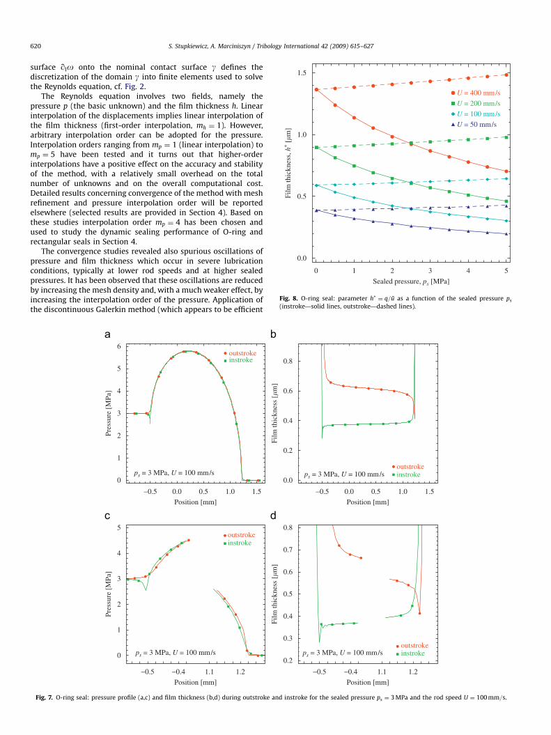
Fig. 10. Rectangular seal: finite element mesh (mesh density 1) in the deformed configuration corresponding to zero sealed pressure (ps ¼ 0) and corner radius
(a) R ¼ 0:1 mm, (b) R ¼ 0:2 mm and (c) R ¼ 0:4 mm.
Table 4Rectangular seal: number of elements and unknowns of the finite element mesh
No. of
solid
elements
No. of
segments for
Reynolds
equation
Total no. of
unknowns
(mp ¼ 4)
No. of
pressure
unknowns
(mp ¼ 4)
Mesh density 1 288 24 735 97
Mesh density 2 1116 48 2550 193
Mesh density 4 4392 96 9420 385
Mesh density 8 17424 192 36 120 769
Mesh density 16 69 408 384 141360 1537
S. Stupkiewicz, A. Marciniszyn / Tribology International 42 (2009) 615–627622
the computations are provided in Table 1. The elastic properties3
of the seal correspond to the NBR rubber (70 ShA hardness) whilethe viscosity is that of the Shell Tellus 46 oil at the workingtemperature of 30 �C.
A structured finite element mesh, significantly refined alongthe lubricated boundary, has been developed. Five mesh densitieshave been used in the computations, cf. Table 2, so thatconvergence with mesh refinement could be examined. Fig. 3shows the undeformed meshes corresponding to three coarsermesh densities (1, 2 and 4). The deformed configurationscorresponding to the sealed pressure ps equal to 0, 1 and 5 MPaare shown in Fig. 4.
As already discussed in Section 3, the solution may exhibitoscillations of pressure and film thickness if the mesh is notfine enough. Generally, the lower the rod speed and the higherthe sealed pressure, the finer mesh is necessary to prevent theoscillations. At the same time, moderate oscillations (occurringtypically in the vicinity of the sudden drop of the film thickness inthe outlet zone) do not significantly affect the overall solution norleakage predictions.
For instance, for ps ¼ 1 MPa and U ¼ 400 mm=s, the leakagerate predicted for mesh density 4 is less than 0.1% lower than theconverged value obtained for mesh density 16, except for mp ¼ 1where the corresponding error is 2%. This is illustrated in Fig. 5which shows the convergence of the leakage rate with meshrefinement and pressure interpolation order. Here and below, theleakage rate is represented by the parameter h�,
h� ¼q
u¼
2q
U, (19)
which can also be interpreted as the film thickness at the point ofmaximum pressure (where dp=dx ¼ 0), cf. Eq. (11)2.
All the detailed results reported below correspond to meshdensity 16. This mesh provides reliable results in the whole rangeof lubrication conditions specified in Table 1, although smalloscillations are observed in the most severe conditions, as it isseen, for instance, in Figs. 6(d) and 7(d). Note that highly accurateresults are obtained also for mesh density 8 except in the case ofinstroke at the severest lubrication conditions in which filmthickness drops below h ¼ 0:2mm.
Figs. 6 and 7 present sample detailed results obtained for theO-ring seal. Pressure profile and lubricant film thickness are
3 Estimated values of parameters m1 and m2. Bulk modulus k is adopted
arbitrarily (sufficiently high to ensure nearly incompressible behavior with the
restriction imposed by the performance of the displacement-based solid elements
used in the present study).
shown for the rod speed U ¼ 100 mm=s and for selected values ofthe sealed pressure ps during outstroke and instroke, and therespective quantities corresponding to ps ¼ 3 MPa are comparedin Fig. 7, including the details of the inlet and outlet zones shownin Fig. 7(c) and (d). Here, the position x ¼ 0 corresponds to thecenter of the cross-section of the seal in the undeformedconfiguration, cf. Fig. 3. Although the friction forces changedirection when the direction of motion is reversed, the action ofthe sealed pressure prevents the seal from moving in its housingand thus the pressure distributions for outstroke and instroke areremarkably close, cf. Fig. 7(a) and (c).
The overall dynamic sealing performance is convenientlycharacterized by the parameter h� ¼ q=u. Figs. 8 and 9 show theeffect of the sealed pressure ps and the rod speed U on the leakagerate represented by h�.
4.2. Rectangular seal
Elastomeric seal of rectangular cross-section is studied as thesecond example. The basic geometrical, material and processparameters used in the computations are provided in Table 3. Thegeometrical parameters correspond to those used by Nikas [9,10](the outer diameter of the seal is not specified in [9,10] thus thevalue of Douter ¼ 60:2 mm has been chosen arbitrarily). In order tostudy the effect of corner radius R, the values R ¼ 0:1 and 0:4 mmhave been studied in addition to R ¼ 0:2 mm, as specified by Nikas[9,10]. Elastic properties of the elastomeric seal and oil viscosityare those used in the O-ring example above.
Again, a family of structured finite element meshes has beendeveloped which is shown in Fig. 10. The mesh is significantlyrefined in the vicinity of the lubricated contact surface and inparticular in the vicinity of corners. Rounding of the outer corners

ARTICLE IN PRESS
S. Stupkiewicz, A. Marciniszyn / Tribology International 42 (2009) 615–627 623
has been neglected as it has a negligible effect on the contactstresses at the lubricated surface. A very coarse mesh can thus beused in that region so that the total number of unknowns isreduced. Table 4 provides the number of elements and unknownsfor five mesh densities used in the present study. Results obtainedfor the finest mesh density 16 are reported below, althoughconvergence studies revealed that in less severe lubricationconditions (i.e. at lower sealed pressures and/or at higher rodspeeds) coarser meshes provide satisfactory results. Position x ¼ 0
Fig. 11. Rectangular seal: details of the deformed finite element mesh (mesh density
(a) R ¼ 0:2 mm and (b) R ¼ 0:4 mm.
R = 0.4 mmR = 0.2 mmR = 0.1 mm
ps = 1 MPa, U = 200 mm/s
0.0
0.5
1.0
1.5
2.0
2.5
R = 0.4 mmR = 0.2 mmR = 0.1 mm
0.0 0.5 1.0 1.5 2.0 2.5 3.0 3.50.0
0.5
1.0
1.5
2.0
2.5
Position [mm]
Pres
sure
[M
Pa]
Pres
sure
[M
Pa]
0.0 0.5 1.0 1.5 2.0 2.5 3.0 3.5
Position [mm]
ps = 1 MPa, U = 200 mm/s
Fig. 12. Rectangular seal: pressure profile (a,c) and film thickness (b,d) during steady-st
speed U ¼ 200 mm=s.
in the figures below corresponds to the sealed-pressure side faceof the seal in the undeformed configuration.
Upon application of the sealed pressure, it is the air-sidecorner that deforms most and the configuration changes in thiszone are significant, cf. Fig. 11. The deformation pattern and, ingeneral, the qualitative features of the solution are essentiallyindependent of the corner radius. This is visible, for instance,on the diagrams of pressure which exhibit two peaks at thecorners and a plateau between them, cf. Fig. 12(a) and (c).
2) corresponding to different values of the sealed pressure ps and corner radius
ps = 1 MPa, U = 200 mm/s
R = 0.4 mmR = 0.2 mmR = 0.1 mm
R = 0.4 mmR = 0.2 mmR = 0.1 mm
0.0
0.1
0.2
0.3
0.4
0.5
0.6
0.7
Film
thic
knes
s [�
m]
ps = 1 MPa, U = 200 mm/s
0.0 0.5 1.0 1.5 2.0 2.5 3.0 3.50.0
0.1
0.2
0.3
0.4
0.5
0.6
0.7
Position [mm]
0.0 0.5 1.0 1.5 2.0 2.5 3.0 3.5
Position [mm]
Film
thic
knes
s [�
m]
ate outstroke (a,b) and instroke (c,d) for the sealed pressure ps ¼ 1 MPa and the rod

ARTICLE IN PRESS
S. Stupkiewicz, A. Marciniszyn / Tribology International 42 (2009) 615–627624
Note that similar pressure peaks at the rounded corners havebeen measured and also predicted by Prati and Strozzi [6]. In thecase of instroke, the pressure profiles are additionally character-ized by a pressure drop in the outlet zone, cf. Fig. 12(c). Similar
outstrokeinstroke
0.1 0.2 3.3 3.4
0.0
0.5
1.0
1.5
2.0
2.5
ps = 1 MPa, U = 200 mm/s, R = 0.2 mm
Position [mm]
Pres
sure
[M
Pa]
Fig. 13. Rectangular seal: details of pressure profile (a) and film thickness (b) durin
U ¼ 200 mm=s.
ps = 9 MPaps = 5 MPaps = 1 MPa
U = 100 mm/s
0.0 0.5 1.0 1.5 2.0 2.5 3.0 3.5
0
2
4
6
8
10
ps = 9 MPaps = 5 MPaps = 1 MPa
Position [mm]
Pres
sure
[M
Pa]
0.0 0.5 1.0 1.5 2.0 2.5 3.0 3.5
Position [mm]
U = 100 mm/s0
2
4
6
8
10
Pres
sure
[M
Pa]
Fig. 14. Rectangular seal: pressure profile (a,c) and film thickness (b,d) during outstro
R ¼ 0:4 mm.
effect is excluded in the case of outstroke due to the cavitationcondition pX0.
The significant effect of the corner radius on the thickness ofthe lubricant film is clearly visible in Fig. 12(b) and (d), however,
outstrokeinstroke
0.1 0.2 3.3 3.4
0.2
0.3
0.4
0.5
0.6
ps = 1 MPa, U = 200 mm/s, R = 0.2 mm
Position [mm]
Film
thic
knes
s [�
m]
g outstroke and instroke for the sealed pressure ps ¼ 1 MPa and the rod speed
ps = 9 MPaps = 5 MPaps = 1 MPa
ps = 9 MPaps = 5 MPaps = 1 MPa
Position [mm]
U = 100 mm/s
0.0 0.5 1.0 1.5 2.0 2.5 3.0 3.5
Position [mm]
0.0 0.5 1.0 1.5 2.0 2.5 3.0 3.5
0.2
0.3
0.4
0.5
0.6
Film
thic
knes
s [�
m]
Film
thic
knes
s [�
m]
U = 100 mm/s0.0
0.1
0.2
0.3
0.4
ke (a,b) and instroke (c,d) for the rod speed U ¼ 100 mm=s and the corner radius
ARTICLE IN PRESS
ps = 0 MPaps = 10 MPa
R = 0.2 mm
1.000.500.200.100.05
Rod speed, U [m/s] Rod speed, U [m/s]
ps = 0 MPaps = 2 MPaps = 4 MPaps = 6 MPaps = 8 MPaps = 10 MPa
R = 0.2 mm
1.000.500.200.100.05
0.10
1.00
0.50
0.20
2.00
0.30
0.15
1.50
0.70
Film
thic
knes
s, h
∗ [�m
]
0.10
1.00
0.50
0.20
2.00
0.30
0.15
1.50
0.70Fi
lm th
ickn
ess,
h∗ [
�m]
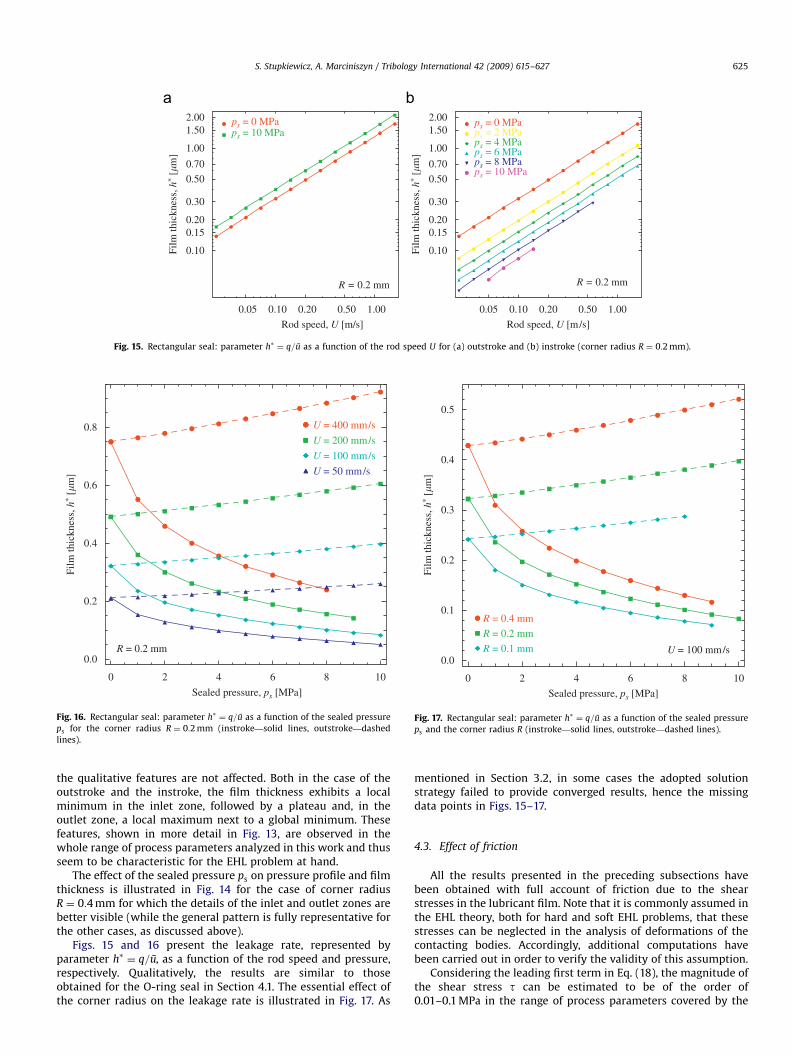
Fig. 15. Rectangular seal: parameter h� ¼ q=u as a function of the rod speed U for (a) outstroke and (b) instroke (corner radius R ¼ 0:2 mm).
U = 400 mm/s
U = 200 mm/s
U = 100 mm/s
U = 50 mm/s
R = 0.2 mm
0 2 4 6 8 10
0.0
0.2
0.4
0.6
0.8
Sealed pressure, ps [MPa]
Film
thic
knes
s, h
∗ [�m
]
Fig. 16. Rectangular seal: parameter h� ¼ q=u as a function of the sealed pressure
ps for the corner radius R ¼ 0:2 mm (instroke—solid lines, outstroke—dashed
lines).
R = 0.4 mm
R = 0.2 mm
R = 0.1 mm U = 100 mm/s
0 2 4 6 8 10
0.0
0.1
0.2
0.3
0.4
0.5
Sealed pressure, ps [MPa]
Film
thic
knes
s, h
∗ [�m
]
Fig. 17. Rectangular seal: parameter h� ¼ q=u as a function of the sealed pressure
ps and the corner radius R (instroke—solid lines, outstroke—dashed lines).
S. Stupkiewicz, A. Marciniszyn / Tribology International 42 (2009) 615–627 625
the qualitative features are not affected. Both in the case of theoutstroke and the instroke, the film thickness exhibits a localminimum in the inlet zone, followed by a plateau and, in theoutlet zone, a local maximum next to a global minimum. Thesefeatures, shown in more detail in Fig. 13, are observed in thewhole range of process parameters analyzed in this work and thusseem to be characteristic for the EHL problem at hand.
The effect of the sealed pressure ps on pressure profile and filmthickness is illustrated in Fig. 14 for the case of corner radiusR ¼ 0:4 mm for which the details of the inlet and outlet zones arebetter visible (while the general pattern is fully representative forthe other cases, as discussed above).
Figs. 15 and 16 present the leakage rate, represented byparameter h� ¼ q=u, as a function of the rod speed and pressure,respectively. Qualitatively, the results are similar to thoseobtained for the O-ring seal in Section 4.1. The essential effect ofthe corner radius on the leakage rate is illustrated in Fig. 17. As
mentioned in Section 3.2, in some cases the adopted solutionstrategy failed to provide converged results, hence the missingdata points in Figs. 15–17.
4.3. Effect of friction
All the results presented in the preceding subsections havebeen obtained with full account of friction due to the shearstresses in the lubricant film. Note that it is commonly assumed inthe EHL theory, both for hard and soft EHL problems, that thesestresses can be neglected in the analysis of deformations of thecontacting bodies. Accordingly, additional computations havebeen carried out in order to verify the validity of this assumption.
Considering the leading first term in Eq. (18), the magnitude ofthe shear stress t can be estimated to be of the order of0.01–0.1 MPa in the range of process parameters covered by the
ARTICLE IN PRESS
S. Stupkiewicz, A. Marciniszyn / Tribology International 42 (2009) 615–627626
present study. These values are 2–3 orders of magnitude smallerthan the hydrodynamic pressures and the shear modulus of theelastomeric seal.
The EHL simulations of the O-ring seal and the rectangular sealhave thus been repeated with friction neglected, i.e. by assumingthat the shear stress t in Eq. (17) vanishes. Firstly, it hasbeen observed that the EHL problems with no friction convergemore easily than the corresponding problems with friction. Inparticular, convergence problems were encountered only in thecase of rectangular seal with the corner radius R ¼ 0:1 mm andsealed pressure ps ¼ 9210 MPa.
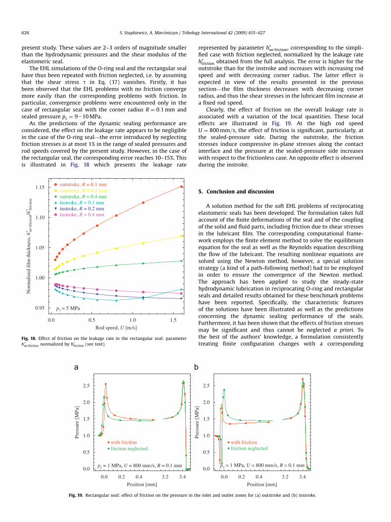
As the predictions of the dynamic sealing performance areconsidered, the effect on the leakage rate appears to be negligiblein the case of the O-ring seal—the error introduced by neglectingfriction stresses is at most 1% in the range of sealed pressures androd speeds covered by the present study. However, in the case ofthe rectangular seal, the corresponding error reaches 10–15%. Thisis illustrated in Fig. 18 which presents the leakage rate
outstroke, R = 0.1 mmoutstroke, R = 0.2 mmoutstroke, R = 0.4 mminstroke, R = 0.1 mminstroke, R = 0.2 mminstroke, R = 0.4 mm
ps = 5 MPa
0.0 0.5 1.0 1.5
0.95
1.00
1.05
1.10
1.15
Rod speed, U [m/s]
Nor
mal
ized
film
thic
knes
s, h
∗ no f
rict
ion/
h∗ fric
tion
Fig. 18. Effect of friction on the leakage rate in the rectangular seal: parameter
h�no friction normalized by h�friction (see text).
with frictionfriction neglected
ps = 1 MPa, U = 800 mm/s, R = 0.1 mm
0.0 0.2 0.4 3.2 3.4
0.0
0.5
1.0
1.5
2.0
2.5
Position [mm]
Pres
sure
[M
Pa]
Fig. 19. Rectangular seal: effect of friction on the pressure in th
represented by parameter h�no friction, corresponding to the simpli-fied case with friction neglected, normalized by the leakage rateh�friction obtained from the full analysis. The error is higher for theoutstroke than for the instroke and increases with increasing rodspeed and with decreasing corner radius. The latter effect isexpected in view of the results presented in the previoussection—the film thickness decreases with decreasing cornerradius, and thus the shear stresses in the lubricant film increase ata fixed rod speed.
Clearly, the effect of friction on the overall leakage rate isassociated with a variation of the local quantities. These localeffects are illustrated in Fig. 19. At the high rod speedU ¼ 800 mm=s, the effect of friction is significant, particularly, atthe sealed-pressure side. During the outstroke, the frictionstresses induce compressive in-plane stresses along the contactinterface and the pressure at the sealed-pressure side increaseswith respect to the frictionless case. An opposite effect is observedduring the instroke.
5. Conclusion and discussion
A solution method for the soft EHL problems of reciprocatingelastomeric seals has been developed. The formulation takes fullaccount of the finite deformations of the seal and of the couplingof the solid and fluid parts, including friction due to shear stressesin the lubricant film. The corresponding computational frame-work employs the finite element method to solve the equilibriumequation for the seal as well as the Reynolds equation describingthe flow of the lubricant. The resulting nonlinear equations aresolved using the Newton method, however, a special solutionstrategy (a kind of a path-following method) had to be employedin order to ensure the convergence of the Newton method.The approach has been applied to study the steady-statehydrodynamic lubrication in reciprocating O-ring and rectangularseals and detailed results obtained for these benchmark problemshave been reported. Specifically, the characteristic featuresof the solutions have been illustrated as well as the predictionsconcerning the dynamic sealing performance of the seals.Furthermore, it has been shown that the effects of friction stressesmay be significant and thus cannot be neglected a priori. Tothe best of the authors’ knowledge, a formulation consistentlytreating finite configuration changes with a corresponding
ps = 1 MPa, U = 800 mm/s, R = 0.1 mm0.0
0.5
1.0
1.5
2.0
2.5
Pres
sure
[M
Pa]
with frictionfriction neglected
0.0 0.2 0.4 3.2 3.4
Position [mm]
e inlet and outlet zones for (a) outstroke and (b) instroke.

ARTICLE IN PRESS
S. Stupkiewicz, A. Marciniszyn / Tribology International 42 (2009) 615–627 627
computational scheme have not been reported in the literature sofar.
The finite configuration changes are clearly visible in the caseof the O-ring seal, as the whole cross-section significantly deformsupon loading by the sealed pressure. This issue is less obvious inthe case of the rectangular seal, however, the related effects areessential also in that case. In fact, the air-side corner deformsseverely and, although it constitutes only a small fraction of thecross-section, this significantly affects the geometry of the inletzone at instroke and of the outlet zone at outstroke.
In view of the geometrical and material nonlinearities, solutionof the deformation problem for the seal is only possible using thefinite element method (or another computational technique) andrequires discretization of the whole cross-section. Consequently,the degrees of freedom directly involved in the Reynolds equation(nodal pressures and nodal displacements at the contact surface)constitute only a small fraction of the global unknowns, and thisratio decreases with mesh refinement. For instance, the finestmeshes, which were necessary for the analysis of the mostdemanding cases, involved more than 100 000 unknowns, ofwhich the pressure unknowns were only about 1 per cent.
In the numerical examples, attention has been paid to theissues of accuracy and convergence of the solutions with meshrefinement. Discussion of the related effects and selected resultshave been presented in this paper, however, the detailed results ofthe convergence studies will be presented in a separate contribu-tion. It has been observed that the severer the lubricationconditions the finer mesh is necessary to obtain an accurate andoscillation-free solution (severe lubrication conditions occur atlow rod speeds and at high sealed pressures, furthermore, theinstroke is usually more demanding than the outstroke). In fact, ifthe mesh is not sufficiently fine, then spurious oscillations ofpressure and film thickness occur, which may additionally lead toconvergence problems. At the same time, mild oscillations do notsignificantly affect the overall solution, including the leakage rate.
Obviously, refinement of the finite element mesh results in theincrease of the computational cost. However, this cost is notprohibitive even for the finest meshes used in the present study.For instance, in the case of the rectangular seal, the completeanalysis of one loading case with the highest mesh density 16takes 45–75 min on a 3.4 GHz Pentium 4 PC, of which 60–70 percent are spent on the pure contact analysis of the seal loaded bythe hydrostatic pressure (first stage of the procedure described inSection 3.2). Note that such a complete analysis provides theresults for the whole range of rod speeds at a fixed sealedpressure. The corresponding CPU time drops down to 5–7 min formesh density 8 and is less than 1 min in the case of mesh density4. The computational efficiency could probably be improved byusing more optimal unstructured meshes and, in particular, byapplying adaptive mesh refinement techniques.
Despite the numerical problems and restrictions mentionedabove, the present approach is capable of providing solutions in awide range of process parameters. Note that, at the lowest rod
speed analyzed (U ¼ 25 mm=s), the thickness of the lubricant filmis as low as 0.1–0.2mm in the case of the O-ring seal and0.03–0.15mm in the case of the rectangular seal. In theseconditions, the effect of surface roughness is expected to besignificant, in particular, the assumption of full-film hydrody-namic lubrication may be inadequate. The present resultscorrespond to an idealized EHL problem for smooth surfaces. Inorder to include the effect of roughness, the flow-factor approach(cf. [18,7]) seems more feasible than the direct treatment of roughsurfaces (e.g. [9]) in view of the required fine discretizations. Onthe other hand, the assumption of separation of scales may beinadequate in the zones of very high gradients of pressure andfilm thickness which have been revealed by the present analysis.
Acknowledgments
This work has been financially supported by the EuropeanCommission through the PROHIPP Project (NMP 2–CT–2004–505466).
References
[1] Nau B. An historical review of studies of polymeric seals in reciprocatinghydraulic systems. Proc Inst Mech Eng Part J J Eng Tribol 1999;213:215–26.
[2] Dowson D, Higginson G. Elasto-hydrodynamic lubrication. Oxford: PergamonPress; 1977.
[3] Muller H, Nau B. Fluid sealing technology, principles and applications.New York: Marcel Dekker, Inc.; 1998.
[4] Ruskell L. A rapidly converging theoretical solution of the elastohydrody-namic problem for rectangular rubber seals. Proc Inst Mech Eng Part C J MechEng Sci 1980;22:9–16.
[5] Yang Y, Hughes W. An elastohydrodynamic analysis of preloaded sliding seals.ASLE Trans 1983;27:197–202.
[6] Prati E, Strozzi A. A study of the elastohydrodynamic problem in rectangularelastomeric seals. Trans ASME J Tribol 1984;106:505–12.
[7] Salant R, Maser N, Yang B. Numerical model of a reciprocating hydraulic rodseal. Trans ASME J Tribol 2007;129:91–7.
[8] Field G, Nau B. A theoretical study of the elastohydrodynamic lubrication ofreciprocating rubber seals. ASLE Trans 1974;18:48–54.
[9] Nikas G. Elastohydrodynamics and mechanics of rectangular elastomericseals for reciprocating piston rods. Trans ASME J Tribol 2003;125:60–9.
[10] Nikas G, Sayles R. Nonlinear elasticity of rectangular elastomeric seals and itseffect on elastohydrodynamic numerical analysis. Tribol Int 2004;37:651–60.
[11] Wriggers P. Computational contact mechanics. Chichester: Wiley; 2002.[12] Alart P, Curnier A. A mixed formulation for frictional contact problems prone
to Newton like solution methods. Comput Meth Appl Mech Eng 1991;92:353–75.
[13] Wu S. A penalty formulation and numerical approximation of the Reynolds–Hertz problem of elastohydrodynamic lubrication. Int J Eng Sci 1986;24:1001–13.
[14] Zienkiewicz O, Taylor R. The finite element method. 5th ed. Oxford:Butterworth, Heinemann; 2000.
[15] Korelc J. AceGen and AceFEM user manuals, Available at: hhttp://www.fgg.uni-lj.si/Symech/i, 2006.
[16] Lu H, Berzins M, Goodyer C, Jimack P. High-order discontinuous Galerkinmethod for elastohydrodynamic lubrication line contact problems. CommunNumer Meth Eng 2005;21:643–50.
[17] Korelc J. Multi-language and multi-environment generation of nonlinearfinite element codes. Eng Comput 2002;18:312–27.
[18] Patir N, Cheng H. An average flow model for determining effects of three-dimensional roughness on partial hydrodynamic lubrication. Trans ASMEJ Lubr Technol 1978;100:12–7.