elc series - john brooks · elc series rohs directive-compliant ... outline of ez-drive closed loop...
TRANSCRIPT
E-126 ORIENTAL MOTOR GENERAL CATALOGUE Features E-126 /General Specifications of Motor E-129 /System Configuration E-130
Mo
torized
Actu
ators
Motorized Cylinders
ELC Series
RoHS Directive-Compliant
●Connection Information●
Technical reference ➜ Page G-1 Safety standards ➜ Page H-4
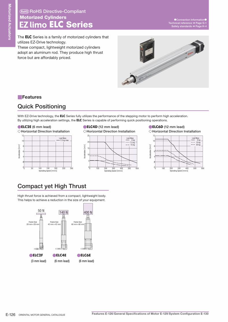
The ELC Series is a family of motorized cylinders that
utilizes EZ-Drive technology.
These compact, lightweight motorized cylinders
adopt an aluminum rod. They produce high thrust
force but are affordably priced.
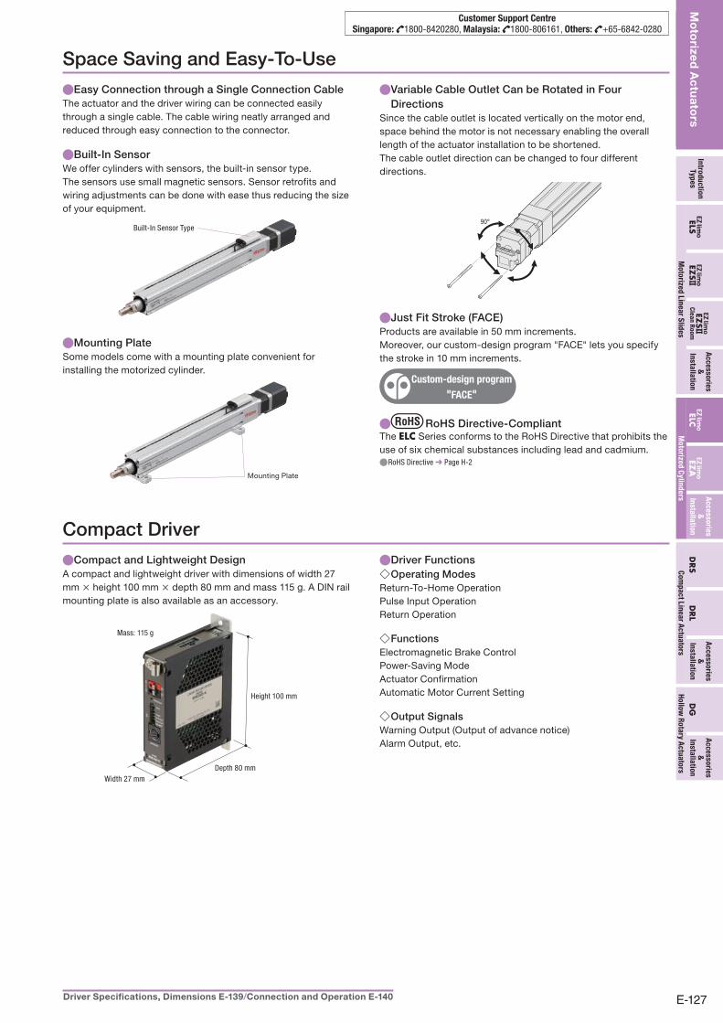
Quick Positioning
With EZ-Drive technology, the ELC Series fully utilizes the performance of the stepping motor to perform high acceleration.
By utilizing high acceleration settings, the ELC Series is capable of performing quick positioning operations.
ELC2E ● (6 mm lead)Horizontal Direction Installation ◇
0
22
4
6
8
10
12
50 100 150 200 250 3000
7.5 kg max.Load Mass
Acce
lera
tion
[ m/s
2 ]
Operating Speed [mm/s]
ELC4D ● (12 mm lead)Horizontal Direction Installation ◇
0
5
10
15
20
25
0 100 200 300 400 500 600
0 kg7.5 kg15 kg
Load Mass
Acce
lera
tion
[ m/s
2 ]
Operating Speed [mm/s]
ELC6D ● (12 mm lead)Horizontal Direction Installation ◇
0
22
4
6
8
10
12
0 100 200 300 400 500 600
0 kg15 kg30 kg
Load Mass
Acce
lera
tion
[ m/s
2 ]
Operating Speed [mm/s]
Compact yet High Thrust
High thrust force is achieved from a compact, lightweight body.
This helps to achieve a reduction in the size of your equipment.
50 N 140 N 400 N
Frame Size28 mm×28 mm
Frame Size42 mm×42 mm
Frame Size60 mm×60 mm
ELC2F ●
(3 mm lead)
ELC4E ●
(6 mm lead)
ELC6E ●
(6 mm lead)
Features■
E-127Driver Specifications, Dimensions E-139 /Connection and Operation E-140
Intro
du
ctio
nTy
pe
sEZ
S ELS
Ac
ce
sso
ries
&
Insta
llatio
nELC
EZA
EZS
Cle
an
Ro
om
DR
SD
RL
Ac
ce
sso
ries
&
Insta
llatio
n
Ac
ce
sso
ries
&
Insta
llatio
n
Mo
torize
d L
ine
ar S
lide
s
Mo
torized
Actu
ators
Mo
torize
d C
ylin
de
rsC
om
pa
ct L
ine
ar A
ctu
ato
rs
DG
Ac
ce
sso
ries
&
Insta
llatio
n
Ho
llow
Ro
tary A
ctu
ato
rs
Customer Support CentreSingapore: 1800-8420280, Malaysia: 1800-806161, Others: +65-6842-0280
Space Saving and Easy-To-Use
Easy Connection through a Single Connection Cable ●The actuator and the driver wiring can be connected easily
through a single cable. The cable wiring neatly arranged and
reduced through easy connection to the connector.
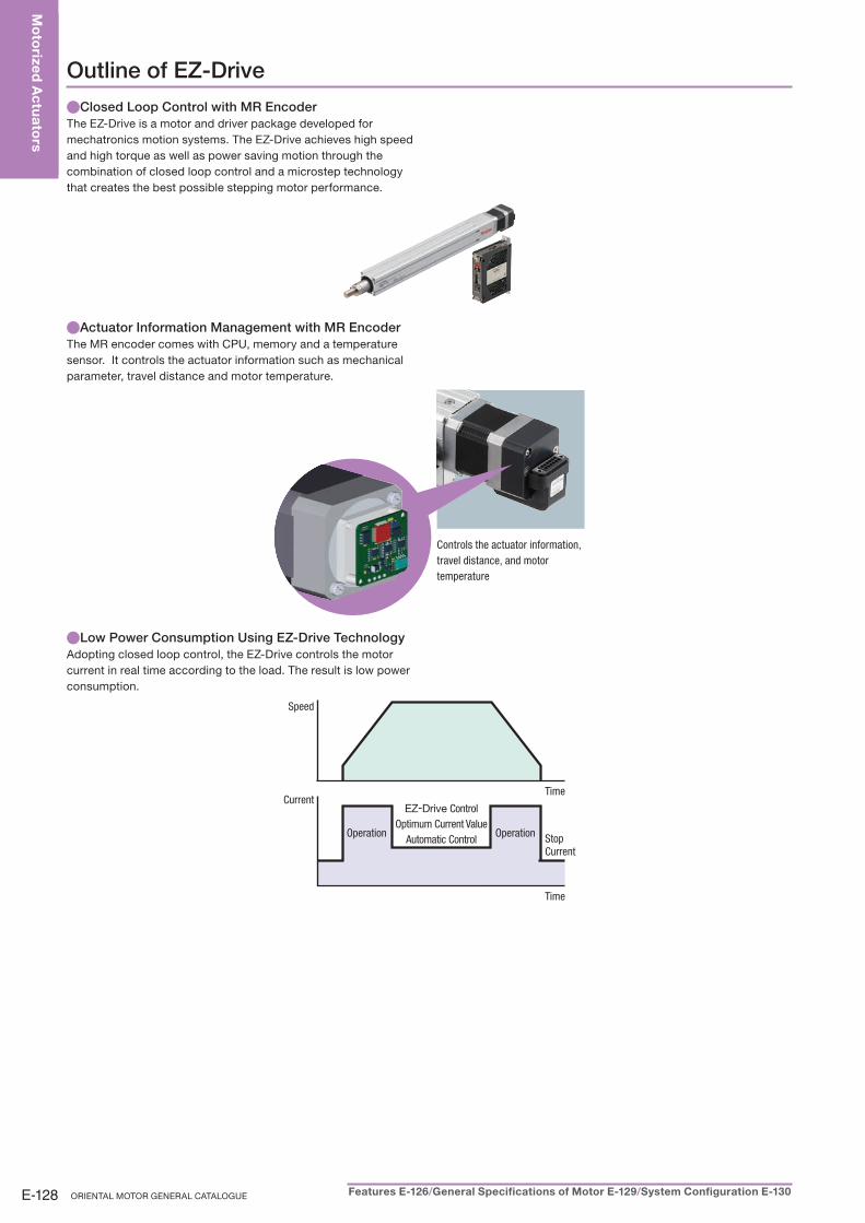
Built-In Sensor ●We offer cylinders with sensors, the built-in sensor type.
The sensors use small magnetic sensors. Sensor retrofits and
wiring adjustments can be done with ease thus reducing the size
of your equipment.
Built-In Sensor Type
Mounting Plate ●Some models come with a mounting plate convenient for
installing the motorized cylinder.
Mounting Plate
Variable Cable Outlet Can be Rotated in Four ●Directions
Since the cable outlet is located vertically on the motor end,
space behind the motor is not necessary enabling the overall
length of the actuator installation to be shortened.
The cable outlet direction can be changed to four different
directions.
90°
Just Fit Stroke (FACE) ●Products are available in 50 mm increments.
Moreover, our custom-design program "FACE" lets you specify
the stroke in 10 mm increments.
Custom-design program
"FACE"
● RoHS Directive-CompliantThe ELC Series conforms to the RoHS Directive that prohibits the
use of six chemical substances including lead and cadmium.
RoHS Directive ● ➜ Page H-2
Compact Driver
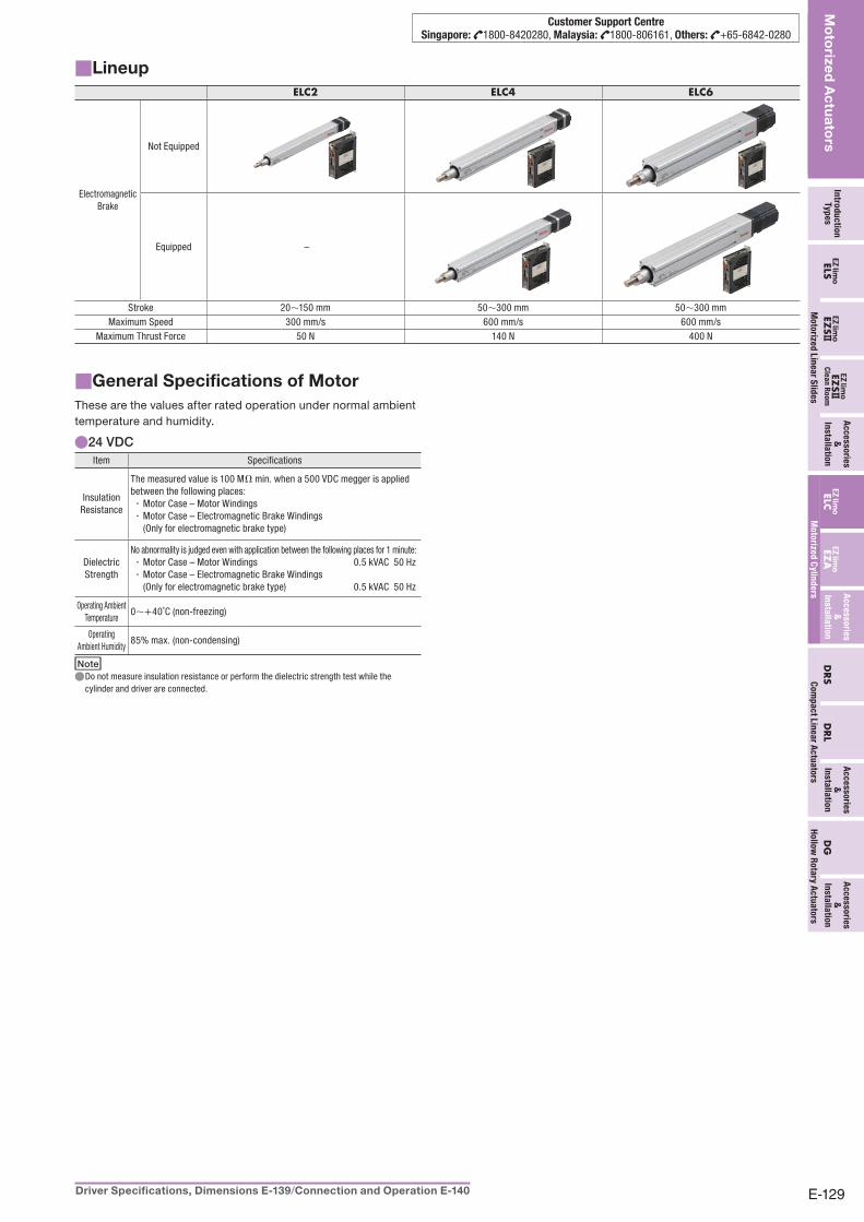
Compact and Lightweight Design ●A compact and lightweight driver with dimensions of width 27
mm × height 100 mm × depth 80 mm and mass 115 g. A DIN rail
mounting plate is also available as an accessory.
Depth 80 mmWidth 27 mm
Height 100 mm
Mass: 115 g
Driver Functions ●Operating Modes ◇
Return-To-Home Operation
Pulse Input Operation
Return Operation
Functions ◇Electromagnetic Brake Control
Power-Saving Mode
Actuator Confirmation
Automatic Motor Current Setting
Output Signals ◇Warning Output (Output of advance notice)
Alarm Output, etc.
E-128 ORIENTAL MOTOR GENERAL CATALOGUE Features E-126 /General Specifications of Motor E-129 /System Configuration E-130
Mo
torized
Actu
ators
Outline of EZ-Drive
Closed Loop Control with MR Encoder ●The EZ-Drive is a motor and driver package developed for
mechatronics motion systems. The EZ-Drive achieves high speed
and high torque as well as power saving motion through the
combination of closed loop control and a microstep technology
that creates the best possible stepping motor performance.
Actuator Information Management with MR Encoder ●The MR encoder comes with CPU, memory and a temperature
sensor. It controls the actuator information such as mechanical
parameter, travel distance and motor temperature.
Controls the actuator information, travel distance, and motor temperature
Low Power Consumption Using EZ-Drive Technology ●Adopting closed loop control, the EZ-Drive controls the motor
current in real time according to the load. The result is low power
consumption.
Speed
TimeCurrent
Time
StopCurrent
Operation Operation
EZ-Drive ControlOptimum Current Value
Automatic Control
E-129Driver Specifications, Dimensions E-139 /Connection and Operation E-140
Intro
du
ctio
nTy
pe
sEZ
S ELS
Ac
ce
sso
ries
&
Insta
llatio
nELC
EZA
EZS
Cle
an
Ro
om
DR
SD
RL
Ac
ce
sso
ries
&
Insta
llatio
n
Ac
ce
sso
ries
&
Insta
llatio
n
Mo
torize
d L
ine
ar S
lide
s
Mo
torized
Actu
ators
Mo
torize
d C
ylin
de
rsC
om
pa
ct L
ine
ar A
ctu
ato
rs
DG
Ac
ce
sso
ries
&
Insta
llatio
n
Ho
llow
Ro
tary A
ctu
ato
rs
Customer Support CentreSingapore: 1800-8420280, Malaysia: 1800-806161, Others: +65-6842-0280
■ General Specifications of MotorThese are the values after rated operation under normal ambient
temperature and humidity.
24 VDC ●Item Specifications
Insulation Resistance
The measured value is 100 MΩ min. when a 500 VDC megger is applied between the following places:
Motor Case – Motor Windings ·Motor Case – Electromagnetic Brake Windings ·(Only for electromagnetic brake type)
Dielectric Strength
No abnormality is judged even with application between the following places for 1 minute:Motor Case – Motor Windings 0.5 kVAC 50 Hz ·Motor Case – Electromagnetic Brake Windings ·(Only for electromagnetic brake type) 0.5 kVAC 50 Hz
Operating Ambient Temperature
0∼+40˚C (non-freezing)
Operating Ambient Humidity
85% max. (non-condensing)
NoteDo not measure insulation resistance or perform the dielectric strength test while the ●cylinder and driver are connected.
Lineup■ELC2 ELC4 ELC6
ElectromagneticBrake
Not Equipped
Equipped –
Stroke 20∼150 mm 50∼300 mm 50∼300 mmMaximum Speed 300 mm/s 600 mm/s 600 mm/s
Maximum Thrust Force 50 N 140 N 400 N
E-130 ORIENTAL MOTOR GENERAL CATALOGUE Features E-126 /General Specifications of Motor E-129 /System Configuration E-130
Mo
torized
Actu
ators
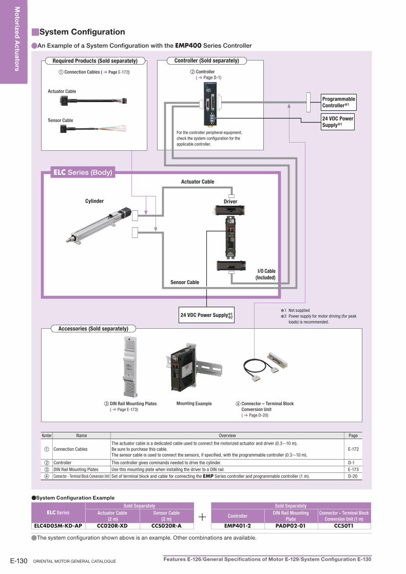
■ System Configuration
An Example of a System Configuration with the ● EMP400 Series Controller
System Configuration Example●
ELC Series
Sold Separately Sold Separately
Actuator Cable
(2 m)
Sensor Cable
(2 m)Controller
DIN Rail Mounting
Plate
Connector – Terminal Block
Conversion Unit (1 m)
ELC4D05M-KD-AP CC020R-XD CCS020R-A EMP401-2 PADP02-01 CC50T1
The system configuration shown above is an example. Other combinations are available. ●
Actuator Cable
Cylinder Driver
Sensor Cable
I/O Cable
(Included)
ELC Series (Body)
③ DIN Rail Mounting Plates
( ➜ Page E-173 )Mounting Example ④ Connector – Terminal Block
Conversion Unit
( ➜ Page D-20 )
Accessories (Sold separately)
Number Name Overview Page
① Connection CablesThe actuator cable is a dedicated cable used to connect the motorized actuator and driver (0.3∼10 m). Be sure to purchase this cable.The sensor cable is used to connect the sensors, if specified, with the programmable controller (0.3∼10 m).
E-172
② Controller This controller gives commands needed to drive the cylinder. D-1 ③ DIN Rail Mounting Plates Use this mounting plate when installing the driver to a DIN rail. E-173 ④ Connector - Terminal Block Conversion Unit Set of terminal block and cable for connecting the EMP Series controller and programmable controller (1 m). D-20
② Controller
( ➜ Page D-1 )
For the controller peripheral equipment, check the system configuration for the applicable controller.
Controller (Sold separately)
① Connection Cables ( ➜ Page E-172 )
Actuator Cable
Sensor Cable
Required Products (Sold separately)
Programmable
Controller✽1
24 VDC Power
Supply✽1
1 Not supplied ✽
2 Power supply for motor driving (for peak ✽
loads) is recommended.
24 VDC Power Supply✽1✽2
E-131Driver Specifications, Dimensions E-139 /Connection and Operation E-140
Intro
du
ctio
nTy
pe
sEZ
S ELS
Ac
ce
sso
ries
&
Insta
llatio
nELC
EZA
EZS
Cle
an
Ro
om
DR
SD
RL
Ac
ce
sso
ries
&
Insta
llatio
n
Ac
ce
sso
ries
&
Insta
llatio
n
Mo
torize
d L
ine
ar S
lide
s
Mo
torized
Actu
ators
Mo
torize
d C
ylin
de
rsC
om
pa
ct L
ine
ar A
ctu
ato
rs
DG
Ac
ce
sso
ries
&
Insta
llatio
n
Ho
llow
Ro
tary A
ctu
ato
rs
Customer Support CentreSingapore: 1800-8420280, Malaysia: 1800-806161, Others: +65-6842-0280
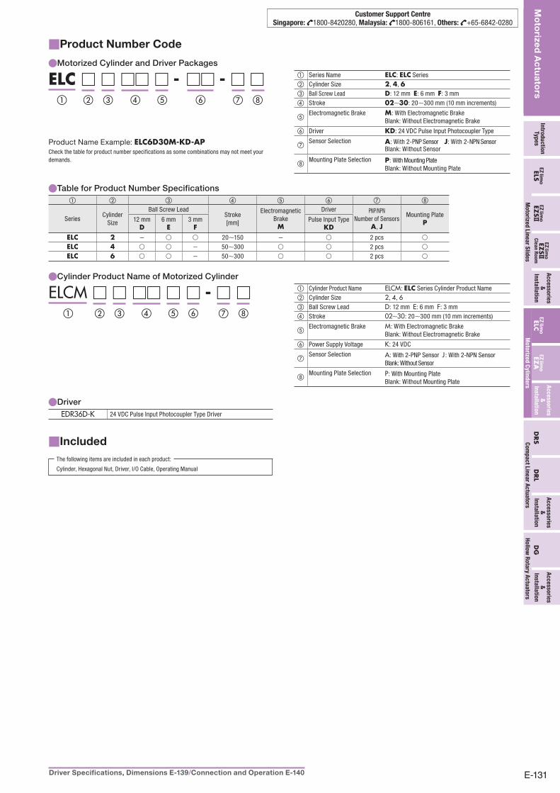
Product Number Code■
Motorized Cylinder and Driver Packages ●
ELC □ □ □□ □ - □□ - □ □① ② ③ ④ ⑦⑥ ⑧⑤
Product Name Example: ELC6D30M-KD-APCheck the table for product number specifications as some combinations may not meet your demands.
① Series Name ELC: ELC Series② Cylinder Size 2, 4, 6③ Ball Screw Lead D: 12 mm E: 6 mm F: 3 mm④ Stroke 02∼30: 20∼300 mm (10 mm increments)
⑤Electromagnetic Brake M: With Electromagnetic Brake Blank: Without Electromagnetic Brake
⑥ Driver KD: 24 VDC Pulse Input Photocoupler Type
⑦Sensor Selection A: With 2-PNP Sensor J: With 2-NPN Sensor Blank: Without Sensor
⑧Mounting Plate Selection P: With Mounting Plate Blank: Without Mounting Plate
Table for Product Number Specifications ●① ② ③ ④ ⑤ ⑥ ⑦ ⑧
SeriesCylinder
Size
Ball Screw LeadStroke[mm]
Electromagnetic BrakeM
Driver PNP/NPNNumber of Sensors
A, J
Mounting Plate P12 mm
D6 mm
E3 mm
FPulse Input Type
KDELC 2 − ○ ○ 20∼150 − ○ 2 pcs ○
ELC 4 ○ ○ − 50∼300 ○ ○ 2 pcs ○
ELC 6 ○ ○ − 50∼300 ○ ○ 2 pcs ○
● Cylinder Product Name of Motorized Cylinder
ELCM □ □ □□ □ □ - □ □① ② ③ ④ ⑦ ⑧⑤ ⑥
① Cylinder Product Name ELCM: ELC Series Cylinder Product Name② Cylinder Size 2, 4, 6③ Ball Screw Lead D: 12 mm E: 6 mm F: 3 mm④ Stroke 02∼30: 20∼300 mm (10 mm increments)
⑤Electromagnetic Brake M: With Electromagnetic Brake Blank: Without Electromagnetic Brake
⑥ Power Supply Voltage K: 24 VDC
⑦Sensor Selection A: With 2-PNP Sensor J : With 2-NPN Sensor Blank: Without Sensor
⑧Mounting Plate Selection P: With Mounting Plate Blank: Without Mounting Plate
Driver ●EDR36D-K 24 VDC Pulse Input Photocoupler Type Driver
Included■The following items are included in each product:
Cylinder, Hexagonal Nut, Driver, I/O Cable, Operating Manual
E-132 ORIENTAL MOTOR GENERAL CATALOGUE Features E-126 /General Specifications of Motor E-129 /System Configuration E-130
Mo
torized
Actu
ators
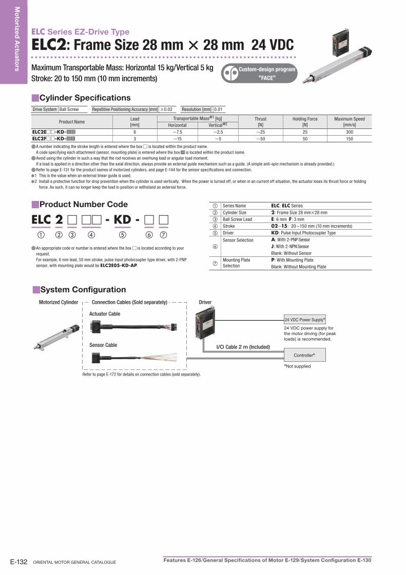
ELC Series EZ-Drive Type
ELC2: Frame Size 28 mm × × 28 mm 24 VDC
Maximum Transportable Mass: Horizontal 15 kg/Vertical 5 kgMaximum Transportable Mass: Horizontal 15 kg/Vertical 5 kg
Stroke: 20 to 150 mm (10 mm increments)Stroke: 20 to 150 mm (10 mm increments)
Custom-design program
"FACE"
Cylinder Specifications ■Drive System Ball Screw Repetitive Positioning Accuracy [mm] ±0.02 Resolution [mm] 0.01
Product NameLead[mm]
Transportable Mass✽1 [kg] Thrust[N]
Holding Force[N]
Maximum Speed[mm/s]Horizontal Vertical✽2
ELC2E□□-KD- ■ ■ ■ ■ 6 ∼7.5 ∼2.5 ∼25 25 300ELC2F□□-KD- ■ ■ ■ ■ 3 ∼15 ∼5 ∼50 50 150
A number indicating the stroke length is entered where the box ● □ is located within the product name.A code specifying each attachment (sensor, mounting plate) is entered where the box ■■ is located within the product name.Avoid using the cylinder in such a way that the rod receives an overhung load or angular load moment. ●If a load is applied in a direction other than the axial direction, always provide an external guide mechanism such as a guide. (A simple anti-spin mechanism is already provided.)Refer to page ● E-131 for the product names of motorized cylinders, and page E-144 for the sensor specifications and connection.
1 This is the value when an external linear guide is used. ✽
2 Install a protective function for drop prevention when the cylinder is used vertically. When the power is turned off, or when in an current off situation, the actuator loses its thrust force or holding ✽
force. As such, it can no longer keep the load in position or withstand an external force.
Product Number Code■
ELC 2 □ □□ - KD - □ □① ② ③ ④ ⑦⑤ ⑥
An appropriate code or number is entered where the box ● □ is located according to your request.For example, 6 mm lead, 50 mm stroke, pulse input photocoupler type driver, with 2-PNP sensor, with mounting plate would be ELC2E05-KD-AP.
① Series Name ELC: ELC Series② Cylinder Size 2: Frame Size 28 mm×28 mm③ Ball Screw Lead E: 6 mm F: 3 mm④ Stroke 02∼15: 20∼150 mm (10 mm increments)⑤ Driver KD: Pulse Input Photocoupler Type
⑥Sensor Selection A: With 2-PNP Sensor
J: With 2-NPN SensorBlank: Without Sensor
⑦Mounting Plate Selection
P: With Mounting PlateBlank: Without Mounting Plate
System Configuration■Motorized Cylinder Connection Cables (Sold separately) Driver
Sensor Cable
Actuator Cable24 VDC Power Supply✽
24 VDC power supply for
the motor driving (for peak
loads) is recommended.
Controller✽
✽Not supplied
I/O Cable 2 m (Included)
Refer to page E-172 for details on connection cables (sold separately).
E-133Driver Specifications, Dimensions E-139 /Connection and Operation E-140
Intro
du
ctio
nTy
pe
sEZ
S ELS
Ac
ce
sso
ries
&
Insta
llatio
nELC
EZA
EZS
Cle
an
Ro
om
DR
SD
RL
Ac
ce
sso
ries
&
Insta
llatio
n
Ac
ce
sso
ries
&
Insta
llatio
n
Mo
torize
d L
ine
ar S
lide
s
Mo
torized
Actu
ators
Mo
torize
d C
ylin
de
rsC
om
pa
ct L
ine
ar A
ctu
ato
rs
DG
Ac
ce
sso
ries
&
Insta
llatio
n
Ho
llow
Ro
tary A
ctu
ato
rs
Customer Support CentreSingapore: 1800-8420280, Malaysia: 1800-806161, Others: +65-6842-0280
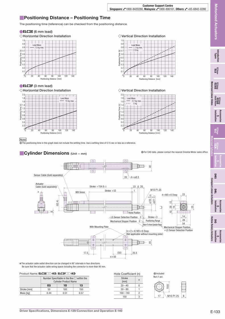
Positioning Distance – Positioning Time■The positioning time (reference) can be checked from the positioning distance.
ELC2E ● (6 mm lead)Horizontal Direction Installation ◇
0
0.5
0.4
0.3
0.2
0.1
0.6
0.7
0.8
0.9
1.0
0 20 40 60 80 100 140120
7.5 kg max.Load Mass
Positioning Distance [mm]
Posi
tioni
ng T
ime
[ s]
Vertical Direction Installation ◇
00 20 40 60 80 100 140120
0.5
0.4
0.3
0.2
0.1
0.6
0.7
0.8
0.9
1.0
2.5 kg1.1 kg max.
Load Mass
Positioning Distance [mm]
Posi
tioni
ng T
ime
[ s]
ELC2F ● (3 mm lead)Horizontal Direction Installation ◇
20 40 60 80 100 120 1400
2.0
1.8
1.6
1.4
1.2
1.0
0.8
0.6
0.4
0.2
0
15 kg max.Load Mass
Positioning Distance [mm]
Posi
tioni
ng T
ime
[ s]
Vertical Direction Installation ◇
20 40 60 80 100 120 1400
2.0
1.8
1.6
1.4
1.2
1.0
0.8
0.6
0.4
0.2
0
Load Mass2.2 kg max. 5 kg
Positioning Distance [mm]
Posi
tioni
ng T
ime
[ s]
NoteThe positioning time in this graph does not include the settling time. Use a settling time of 0.15 sec or less as a reference. ●
Cylinder Dimensions■ (Unit = mm)For CAD data, please contact the nearest Oriental Motor sales office. ●
4×ϕ6.520
40
( 62.
4)
2023 6
1 M10 P1.25
ϕ18
−0.
040
ϕ27
−0.
10
2
3
1228 23
14
20
25.5(50)
n×5017.5
23
1410
54
6
28
✽
Sensor Cable (Sold separately)
Stroke +53With Sensor
Stroke +154.6±2
With Mounting Plate
(n×2+4) M3×6 Deep(Not applicable without mounting plate)
Stroke+3Positioning Range
Return-To-Home Operation RangeMechanical Stopper Position
−LS Sensor Detection Position
Mechanical Stopper Position, +LS Sensor Detection Position
Home Position
ActuatorCable (Sold separately)
4×M3×6 Deep
The actuator cable outlet direction can be changed in 90˚ intervals in four directions. ✽
Be sure that the actuator cable wiring space including the connector is more than 90 mm.
Product Name: ELC2E□□-KD, ELC2F□□-KD
Number Specifiable in the Box □ within the Cylinder Product Name
05 10 15Stroke [mm] 50 100 150Mass [kg] 0.44 0.51 0.57
Hole Coefficient (n) Included ●Nut (1 pc)
Stroke[mm]
n
M10 P1.25
19.6
17 8
20∼40 050∼90 1
100∼140 2150 3
E-134 ORIENTAL MOTOR GENERAL CATALOGUE Features E-126 /General Specifications of Motor E-129 /System Configuration E-130
Mo
torized
Actu
ators
ELC Series EZ-Drive Type
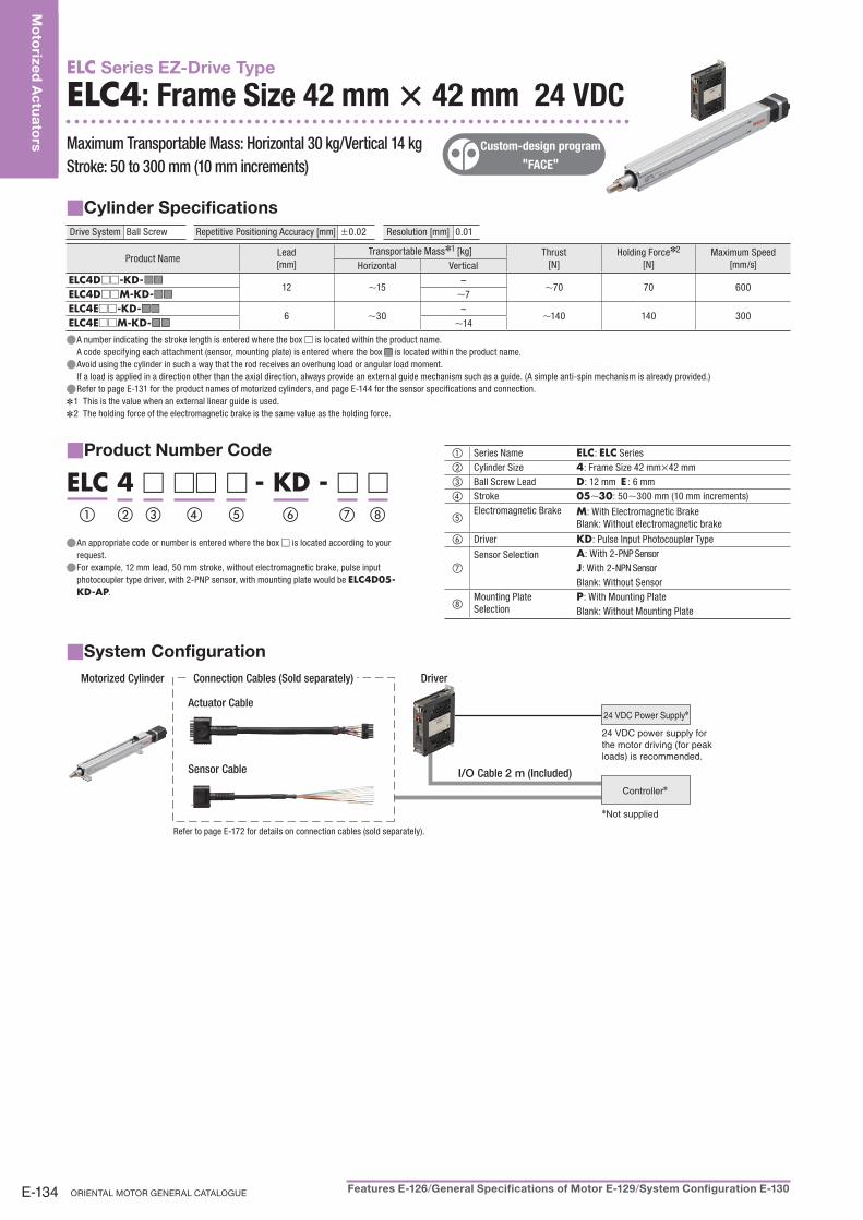
ELC4: Frame Size 42 mm × × 42 mm 24 VDC
Maximum Transportable Mass: Horizontal 30 kg/Vertical 14 kgMaximum Transportable Mass: Horizontal 30 kg/Vertical 14 kg
Stroke: 50 to 300 mm (10 mm increments)Stroke: 50 to 300 mm (10 mm increments)
Custom-design program
"FACE"
Cylinder Specifications ■Drive System Ball Screw Repetitive Positioning Accuracy [mm] ±0.02 Resolution [mm] 0.01
Product NameLead[mm]
Transportable Mass✽1 [kg] Thrust[N]
Holding Force✽2
[N]Maximum Speed
[mm/s]Horizontal VerticalELC4D□□-KD- ■ ■ ■ ■
12 ∼15–
∼70 70 600ELC4D□□M-KD- ■ ■ ■ ■ ∼7ELC4E□□-KD- ■ ■ ■ ■
6 ∼30–
∼140 140 300ELC4E□□M-KD- ■ ■ ■ ■ ∼14
A number indicating the stroke length is entered where the box ● □ is located within the product name.A code specifying each attachment (sensor, mounting plate) is entered where the box ■■ is located within the product name.Avoid using the cylinder in such a way that the rod receives an overhung load or angular load moment. ●If a load is applied in a direction other than the axial direction, always provide an external guide mechanism such as a guide. (A simple anti-spin mechanism is already provided.)Refer to page ● E-131 for the product names of motorized cylinders, and page E-144 for the sensor specifications and connection.
1 This is the value when an external linear guide is used. ✽
2 The holding force of the electromagnetic brake is the same value as the holding force. ✽
Product Number Code■
ELC 4 □ □□ □ - KD - □ □① ② ③ ④ ⑧⑥ ⑦⑤
An appropriate code or number is entered where the box ● □ is located according to your request.For example, 12 mm lead, 50 mm stroke, without electromagnetic brake, pulse input ●photocoupler type driver, with 2-PNP sensor, with mounting plate would be ELC4D05-KD-AP.
① Series Name ELC: ELC Series② Cylinder Size 4: Frame Size 42 mm×42 mm③ Ball Screw Lead D: 12 mm E : 6 mm④ Stroke 05∼30: 50∼300 mm (10 mm increments)
⑤Electromagnetic Brake M: With Electromagnetic Brake
Blank: Without electromagnetic brake
⑥ Driver KD: Pulse Input Photocoupler Type
⑦Sensor Selection A: With 2-PNP Sensor
J: With 2-NPN SensorBlank: Without Sensor
⑧Mounting Plate Selection
P: With Mounting PlateBlank: Without Mounting Plate
System Configuration■Motorized Cylinder Connection Cables (Sold separately) Driver
Sensor Cable
Actuator Cable24 VDC Power Supply✽
24 VDC power supply for
the motor driving (for peak
loads) is recommended.
Controller✽
✽Not supplied
I/O Cable 2 m (Included)
Refer to page E-172 for details on connection cables (sold separately).
E-135Driver Specifications, Dimensions E-139 /Connection and Operation E-140
Intro
du
ctio
nTy
pe
sEZ
S ELS
Ac
ce
sso
ries
&
Insta
llatio
nELC
EZA
EZS
Cle
an
Ro
om
DR
SD
RL
Ac
ce
sso
ries
&
Insta
llatio
n
Ac
ce
sso
ries
&
Insta
llatio
n
Mo
torize
d L
ine
ar S
lide
s
Mo
torized
Actu
ators
Mo
torize
d C
ylin
de
rsC
om
pa
ct L
ine
ar A
ctu
ato
rs
DG
Ac
ce
sso
ries
&
Insta
llatio
n
Ho
llow
Ro
tary A
ctu
ato
rs
Customer Support CentreSingapore: 1800-8420280, Malaysia: 1800-806161, Others: +65-6842-0280
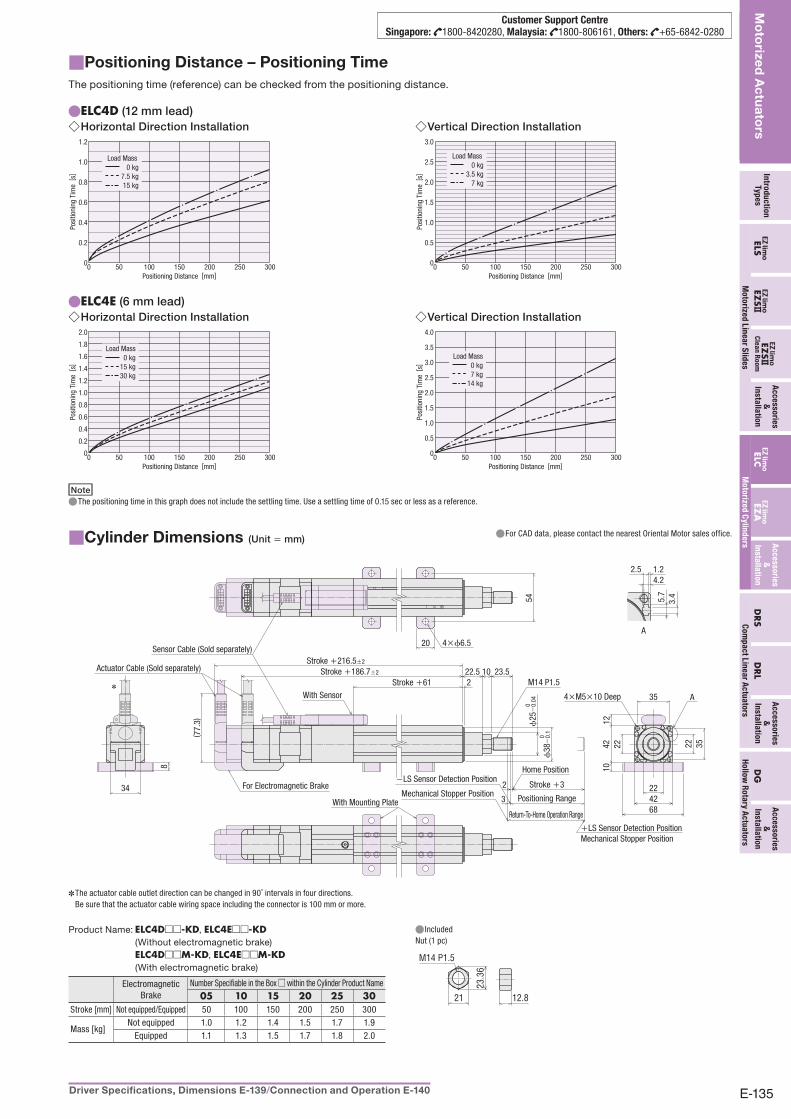
Positioning Distance – Positioning Time■The positioning time (reference) can be checked from the positioning distance.
ELC4D ● (12 mm lead)Horizontal Direction Installation ◇
1.2
1.0
0.8
0.6
0.4
0.2
00 50 100 150 200 250 300
0 kg7.5 kg15 kg
Load Mass
Positioning Distance [mm]
Posi
tioni
ng T
ime
[ s]
Vertical Direction Installation ◇3.0
2.5
2.0
1.5
1.0
0.5
00 50 100 150 200 250 300
0 kg3.5 kg
7 kg
Load Mass
Positioning Distance [mm]
Posi
tioni
ng T
ime
[ s]
ELC4E ● (6 mm lead)Horizontal Direction Installation ◇
2.0
1.6
1.4
1.8
1.2
1.0
0.8
0.6
0.4
0.2
00 50 100 150 200 250 300
0 kg15 kg30 kg
Load Mass
Positioning Distance [mm]
Posi
tioni
ng T
ime
[ s]
Vertical Direction Installation ◇4.0
3.5
3.0
2.5
2.0
1.5
1.0
0.5
00 50 100 150 200 250 300
0 kg7 kg
14 kg
Load Mass
Positioning Distance [mm]
Posi
tioni
ng T
ime
[ s]
NoteThe positioning time in this graph does not include the settling time. Use a settling time of 0.15 sec or less as a reference. ●
Cylinder Dimensions■ (Unit = mm)For CAD data, please contact the nearest Oriental Motor sales office. ●
2
( 77.
3)
22.5 23.510
3
2
42
4222
2212
10
68
8
34
3535
22
3.45.7
1.22.54.2
A
54
20
A
M14 P1.5
ϕ38
−0.
10
ϕ25
−0.
040
4×ϕ6.5
Stroke +61
With Sensor 4×M5×10 Deep
Sensor Cable (Sold separately)
With Mounting Plate
Stroke +3
Positioning Range
Return-To-Home Operation Range
Actuator Cable (Sold separately)
For Electromagnetic BrakeMechanical Stopper Position
−LS Sensor Detection PositionHome Position
Stroke +216.5±2
Stroke +186.7±2
+LS Sensor Detection PositionMechanical Stopper Position
✽
The actuator cable outlet direction can be changed in 90˚ intervals in four directions. ✽
Be sure that the actuator cable wiring space including the connector is 100 mm or more.
Product Name: ELC4D□□-KD, ELC4E□□-KD (Without electromagnetic brake)
ELC4D□□M-KD, ELC4E□□M-KD (With electromagnetic brake)
Electromagnetic Brake
Number Specifiable in the Box □ within the Cylinder Product Name05 10 15 20 25 30
Stroke [mm] Not equipped/Equipped 50 100 150 200 250 300
Mass [kg]Not equipped 1.0 1.2 1.4 1.5 1.7 1.9
Equipped 1.1 1.3 1.5 1.7 1.8 2.0
Included ●Nut (1 pc)
M14 P1.5
12.821
23.3
6
E-136 ORIENTAL MOTOR GENERAL CATALOGUE Features E-126 /General Specifications of Motor E-129 /System Configuration E-130
Mo
torized
Actu
ators
ELC Series EZ-Drive Type
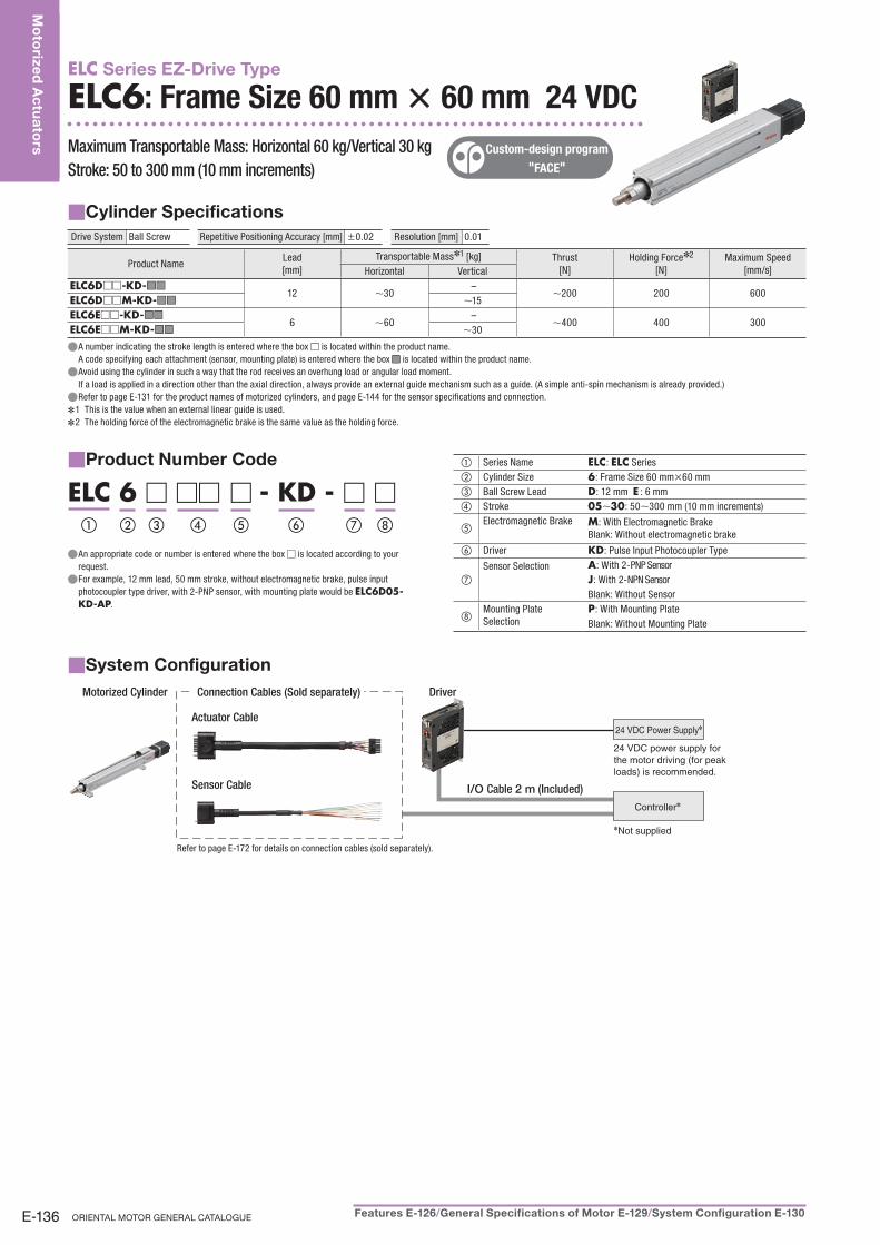
ELC6: Frame Size 60 mm × × 60 mm 24 VDC
Maximum Transportable Mass: Horizontal 60 kg/Vertical 30 kgMaximum Transportable Mass: Horizontal 60 kg/Vertical 30 kg
Stroke: 50 to 300 mm (10 mm increments)Stroke: 50 to 300 mm (10 mm increments)
Custom-design program
"FACE"
Cylinder Specifications ■Drive System Ball Screw Repetitive Positioning Accuracy [mm] ±0.02 Resolution [mm] 0.01
Product NameLead[mm]
Transportable Mass✽1 [kg] Thrust[N]
Holding Force✽2
[N]Maximum Speed
[mm/s]Horizontal VerticalELC6D□□-KD- ■ ■ ■ ■
12 ∼30 –
∼200 200 600ELC6D□□M-KD- ■ ■ ■ ■ ∼15ELC6E□□-KD- ■ ■ ■ ■
6 ∼60 –
∼400 400 300ELC6E□□M-KD- ■ ■ ■ ■ ∼30
A number indicating the stroke length is entered where the box ● □ is located within the product name.A code specifying each attachment (sensor, mounting plate) is entered where the box ■■ is located within the product name.Avoid using the cylinder in such a way that the rod receives an overhung load or angular load moment. ●If a load is applied in a direction other than the axial direction, always provide an external guide mechanism such as a guide. (A simple anti-spin mechanism is already provided.)Refer to page ● E-131 for the product names of motorized cylinders, and page E-144 for the sensor specifications and connection.
1 This is the value when an external linear guide is used. ✽
2 The holding force of the electromagnetic brake is the same value as the holding force. ✽
Product Number Code■
ELC 6 □ □□ □ - KD - □ □① ② ③ ④ ⑧⑥ ⑦⑤
An appropriate code or number is entered where the box ● □ is located according to your request.For example, 12 mm lead, 50 mm stroke, without electromagnetic brake, pulse input ●photocoupler type driver, with 2-PNP sensor, with mounting plate would be ELC6D05-KD-AP.
① Series Name ELC: ELC Series② Cylinder Size 6: Frame Size 60 mm×60 mm③ Ball Screw Lead D: 12 mm E : 6 mm④ Stroke 05∼30: 50∼300 mm (10 mm increments)
⑤Electromagnetic Brake M: With Electromagnetic Brake
Blank: Without electromagnetic brake
⑥ Driver KD: Pulse Input Photocoupler Type
⑦Sensor Selection A: With 2-PNP Sensor
J: With 2-NPN SensorBlank: Without Sensor
⑧Mounting Plate Selection
P: With Mounting PlateBlank: Without Mounting Plate
System Configuration■Motorized Cylinder Connection Cables (Sold separately) Driver
Sensor Cable
Actuator Cable24 VDC Power Supply✽
24 VDC power supply for
the motor driving (for peak
loads) is recommended.
Controller✽
✽Not supplied
I/O Cable 2 m (Included)
Refer to page E-172 for details on connection cables (sold separately).
E-137Driver Specifications, Dimensions E-139 /Connection and Operation E-140
Intro
du
ctio
nTy
pe
sEZ
S ELS
Ac
ce
sso
ries
&
Insta
llatio
nELC
EZA
EZS
Cle
an
Ro
om
DR
SD
RL
Ac
ce
sso
ries
&
Insta
llatio
n
Ac
ce
sso
ries
&
Insta
llatio
n
Mo
torize
d L
ine
ar S
lide
s
Mo
torized
Actu
ators
Mo
torize
d C
ylin
de
rsC
om
pa
ct L
ine
ar A
ctu
ato
rs
DG
Ac
ce
sso
ries
&
Insta
llatio
n
Ho
llow
Ro
tary A
ctu
ato
rs
Customer Support CentreSingapore: 1800-8420280, Malaysia: 1800-806161, Others: +65-6842-0280
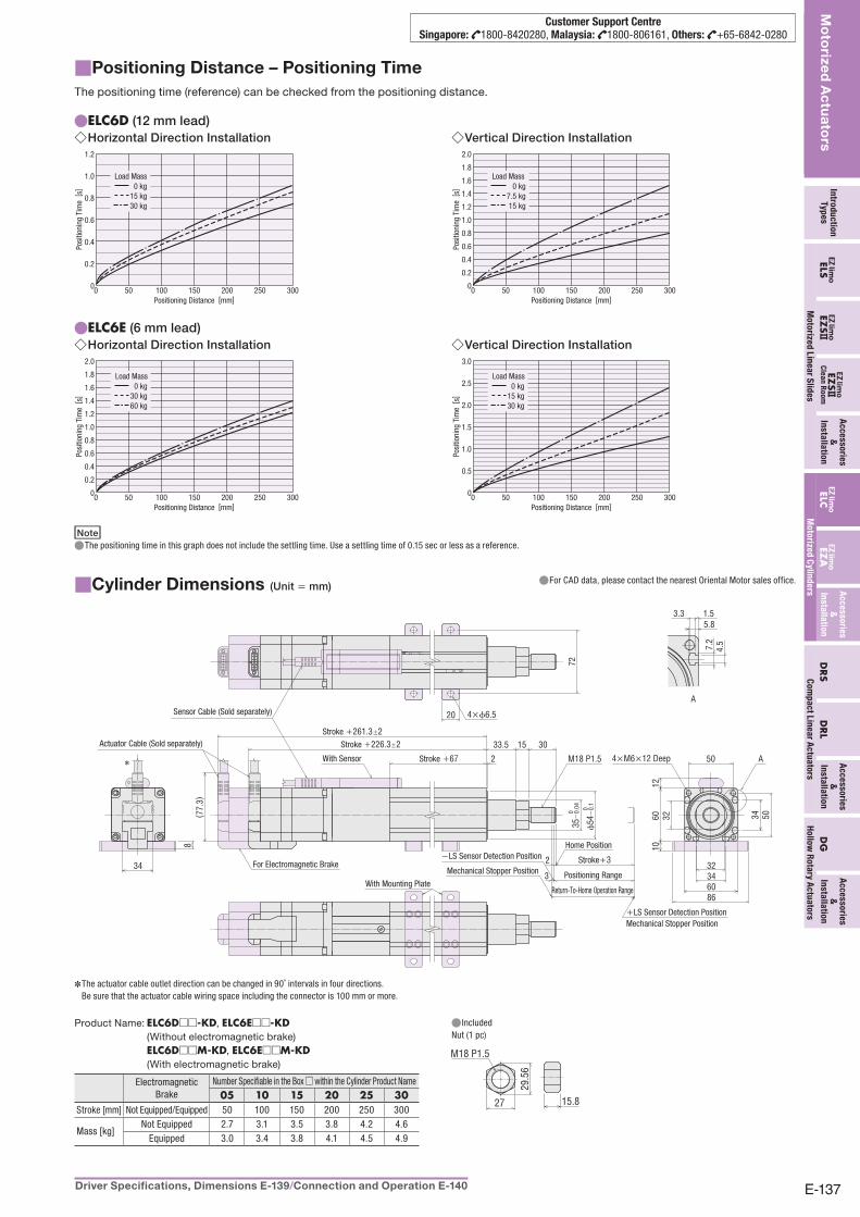
Positioning Distance – Positioning Time■The positioning time (reference) can be checked from the positioning distance.
ELC6D ● (12 mm lead)Horizontal Direction Installation ◇
1.2
1.0
0.8
0.6
0.4
0.2
00 50 100 150 200 250 300
0 kg15 kg30 kg
Load Mass
Positioning Distance [mm]
Posi
tioni
ng T
ime
[ s]
Vertical Direction Installation ◇2.0
1.8
1.6
1.4
1.2
1.0
0.8
0.6
0.4
0.2
00 50 100 150 200 250 300
0 kg7.5 kg15 kg
Load Mass
Positioning Distance [mm]
Posi
tioni
ng T
ime
[ s]
ELC6E ● (6 mm lead)Horizontal Direction Installation ◇
2.0
1.8
1.6
1.4
1.2
1.0
0.8
0.6
0.4
0.2
00 50 100 150 200 250 300
0 kg30 kg60 kg
Load Mass
Positioning Distance [mm]
Posi
tioni
ng T
ime
[ s]
Vertical Direction Installation ◇3.0
2.5
2.0
1.5
1.0
0.5
00 50 100 150 200 250 300
0 kg15 kg30 kg
Load Mass
Positioning Distance [mm]
Posi
tioni
ng T
ime
[ s]
NoteThe positioning time in this graph does not include the settling time. Use a settling time of 0.15 sec or less as a reference. ●
Cylinder Dimensions■ (Unit = mm)For CAD data, please contact the nearest Oriental Motor sales office. ●
33.5 15 30
2 A
32
34
8( 7
7.3)
M18 P1.5
3
2
5034 50
1060
12
32
6086
A
72
20
34
4.57.2
1.53.35.8
✽
4×ϕ6.5
35−
0.04
0
ϕ54
−0.
10
Sensor Cable (Sold separately)
With Mounting Plate
Stroke +67
Stroke +261.3±2Stroke +226.3±2
Stroke+3
Positioning Range
Return-To-Home Operation Range
4×M6×12 DeepWith Sensor
For Electromagnetic BrakeMechanical Stopper Position
−LS Sensor Detection PositionHome Position
Actuator Cable (Sold separately)
+LS Sensor Detection PositionMechanical Stopper Position
The actuator cable outlet direction can be changed in 90˚ intervals in four directions. ✽
Be sure that the actuator cable wiring space including the connector is 100 mm or more.
Product Name: ELC6D□□-KD, ELC6E□□-KD (Without electromagnetic brake)
ELC6D□□M-KD, ELC6E□□M-KD (With electromagnetic brake)
Electromagnetic Brake
Number Specifiable in the Box □ within the Cylinder Product Name05 10 15 20 25 30
Stroke [mm] Not Equipped/Equipped 50 100 150 200 250 300
Mass [kg]Not Equipped 2.7 3.1 3.5 3.8 4.2 4.6
Equipped 3.0 3.4 3.8 4.1 4.5 4.9
Included ●Nut (1 pc)
M18 P1.5
15.827
29.5
6
E-138 ORIENTAL MOTOR GENERAL CATALOGUE Features E-126 /General Specifications of Motor E-129 /System Configuration E-130
Mo
torized
Actu
ators
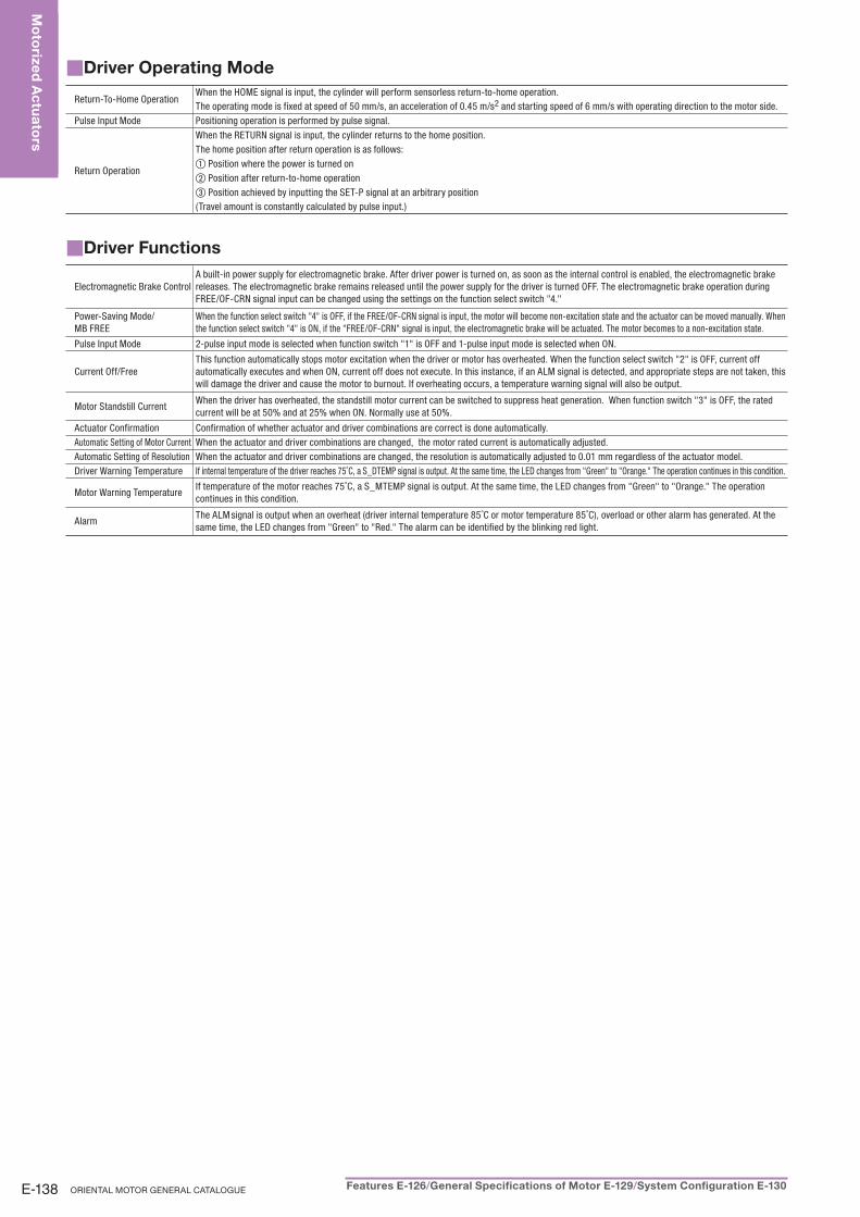
Driver Operating Mode■
Return-To-Home OperationWhen the HOME signal is input, the cylinder will perform sensorless return-to-home operation.The operating mode is fixed at speed of 50 mm/s, an acceleration of 0.45 m/s2 and starting speed of 6 mm/s with operating direction to the motor side.
Pulse Input Mode Positioning operation is performed by pulse signal.
Return Operation
When the RETURN signal is input, the cylinder returns to the home position.The home position after return operation is as follows:① Position where the power is turned on② Position after return-to-home operation③ Position achieved by inputting the SET-P signal at an arbitrary position (Travel amount is constantly calculated by pulse input.)
Driver Functions■
Electromagnetic Brake ControlA built-in power supply for electromagnetic brake. After driver power is turned on, as soon as the internal control is enabled, the electromagnetic brake releases. The electromagnetic brake remains released until the power supply for the driver is turned OFF. The electromagnetic brake operation during FREE/OF-CRN signal input can be changed using the settings on the function select switch "4."
Power-Saving Mode/MB FREE
When the function select switch "4" is OFF, if the FREE/OF-CRN signal is input, the motor will become non-excitation state and the actuator can be moved manually. When the function select switch "4" is ON, if the "FREE/OF-CRN" signal is input, the electromagnetic brake will be actuated. The motor becomes to a non-excitation state.
Pulse Input Mode 2-pulse input mode is selected when function switch "1" is OFF and 1-pulse input mode is selected when ON.
Current Off/FreeThis function automatically stops motor excitation when the driver or motor has overheated. When the function select switch "2" is OFF, current off automatically executes and when ON, current off does not execute. In this instance, if an ALM signal is detected, and appropriate steps are not taken, this will damage the driver and cause the motor to burnout. If overheating occurs, a temperature warning signal will also be output.
Motor Standstill CurrentWhen the driver has overheated, the standstill motor current can be switched to suppress heat generation. When function switch "3" is OFF, the rated current will be at 50% and at 25% when ON. Normally use at 50%.
Actuator Confirmation Confirmation of whether actuator and driver combinations are correct is done automatically. Automatic Setting of Motor Current When the actuator and driver combinations are changed, the motor rated current is automatically adjusted. Automatic Setting of Resolution When the actuator and driver combinations are changed, the resolution is automatically adjusted to 0.01 mm regardless of the actuator model. Driver Warning Temperature If internal temperature of the driver reaches 75˚C, a S_DTEMP signal is output. At the same time, the LED changes from "Green" to "Orange." The operation continues in this condition.
Motor Warning TemperatureIf temperature of the motor reaches 75˚C, a S_MTEMP signal is output. At the same time, the LED changes from "Green" to "Orange." The operation continues in this condition.
AlarmThe ALM signal is output when an overheat (driver internal temperature 85˚C or motor temperature 85˚C), overload or other alarm has generated. At the same time, the LED changes from "Green" to "Red." The alarm can be identified by the blinking red light.
E-139Driver Specifications, Dimensions E-139 /Connection and Operation E-140
Intro
du
ctio
nTy
pe
sEZ
S ELS
Ac
ce
sso
ries
&
Insta
llatio
nELC
EZA
EZS
Cle
an
Ro
om
DR
SD
RL
Ac
ce
sso
ries
&
Insta
llatio
n
Ac
ce
sso
ries
&
Insta
llatio
n
Mo
torize
d L
ine
ar S
lide
s
Mo
torized
Actu
ators
Mo
torize
d C
ylin
de
rsC
om
pa
ct L
ine
ar A
ctu
ato
rs
DG
Ac
ce
sso
ries
&
Insta
llatio
n
Ho
llow
Ro
tary A
ctu
ato
rs
Customer Support CentreSingapore: 1800-8420280, Malaysia: 1800-806161, Others: +65-6842-0280
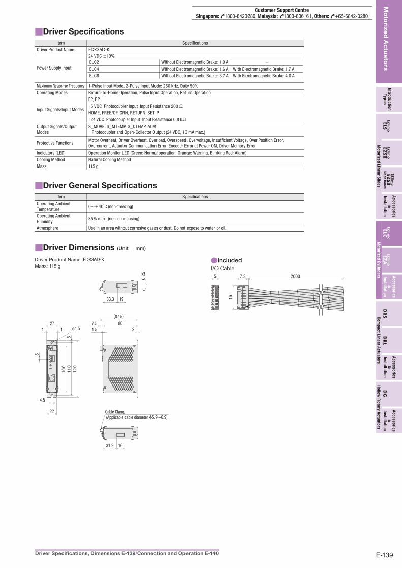
■ Driver SpecificationsItem Specifications
Driver Product Name EDR36D-K
Power Supply Input
24 VDC ±10%ELC2 Without Electromagnetic Brake: 1.0 A −
ELC4 Without Electromagnetic Brake: 1.6 A With Electromagnetic Brake: 1.7 A ELC6 Without Electromagnetic Brake: 3.7 A With Electromagnetic Brake: 4.0 A
Maximum Response Frequency 1-Pulse Input Mode, 2-Pulse Input Mode: 250 kHz, Duty 50%Operating Modes Return-To-Home Operation, Pulse Input Operation, Return Operation
Input Signals/Input Modes
FP, RP 5 VDC Photocoupler Input Input Resistance 200 ΩHOME, FREE/OF-CRN, RETURN, SET-P 24 VDC Photocoupler Input Input Resistance 6.8 kΩ
Output Signals/Output Modes
S_MOVE, S_MTEMP, S_DTEMP, ALM Photocoupler and Open-Collector Output (24 VDC, 10 mA max.)
Protective FunctionsMotor Overheat, Driver Overheat, Overload, Overspeed, Overvoltage, Insufficient Voltage, Over Position Error, Overcurrent, Actuator Communication Error, Encoder Error at Power ON, Driver Memory Error
Indicators (LED) Operation Monitor LED (Green: Normal operation, Orange: Warning, Blinking Red: Alarm)Cooling Method Natural Cooling MethodMass 115 g
Driver General Specifications■Item Specifications
Operating Ambient Temperature
0∼+40˚C (non-freezing)
Operating Ambient Humidity
85% max. (non-condensing)
Atmosphere Use in an area without corrosive gases or dust. Do not expose to water or oil.
Driver Dimensions■ (Unit = mm)
Driver Product Name: EDR36D-KMass: 115 g
33.3 19
100
110
120
5
ϕ4.5
5
2711
76.
25
1631.9
22
807.5
(87.5)
1.5 2
4.5
Cable Clamp (Applicable cable diameter ϕ5.9∼6.9)
Included ●I/O Cable
20007.35
16