elcometer 456 coating thickness gauge grobe range instructions
TRANSCRIPT

Operating Instructions
The New Elcometer 456
Coating Thickness Gauge
DFTTECH.COM

Gauge Dimensions: 141 x 73 x 37mm (5.55 x 2.87 x 1.46").
Gauge Weight: Integral: 156g (5.5oz) including batteries; Separate: 161g (5.68oz) including batteries.
Applicable patents: US6243 661; US5886522; US6762603; US7606671; GB2306009; GB2367135; GB2342450, DE10131827
© Elcometer Limited 2012 - 2015. All rights reserved. No part of this document may be reproduced, transmitted, transcribed, stored (in a retrieval system or otherwise) or translated into any language, in any form or by any means (electronic, mechanical, magnetic, optical, manual or otherwise) without the prior written permission of Elcometer Limited.
www.elcometer.comTMA-0489 Issue 10
R
en
Pb Hg
DFTTECH.COM

Section Page
1 GAUGE OVERVIEW AND BOX CONTENTS........................................................... 4
2 GETTING STARTED................................................................................................. 5
3 TAKING A READING................................................................................................. 7
4 CALIBRATING THE GAUGE.................................................................................... 8
5 THE DISPLAY........................................................................................................... 9
6 THE GAUGE FEATURES......................................................................................... 12
7 MEASUREMENT MODES (ST)................................................................................ 25
8 BATCHING (ST)........................................................................................................ 26
9 DOWNLOADING DATA USING ELCOMASTER (BST)............................................ 35
10 ELCOMASTER MOBILE APPS (ST)........................................................................ 55
11 CLOUD COMPUTING USING ELCOMASTER (ST)................................................ 56
12 GETTING THE MOST OUT OF ELCOMASTER...................................................... 58
13 CALIBRATING THE ELCOMETER 456 (EBST)....................................................... 60
14 CHANGING THE WELCOME SCREEN (BST)......................................................... 64
15 GAUGE FIRMWARE UPDATES (BST).................................................................... 65
16 GAUGE ICONS & ERROR CODES (EBST)............................................................. 66
17 GAUGE MENU STRUCTURES (EBST)................................................................... 70
18 ABOUT IMO PSPC (ST)........................................................................................... 74
19 GAUGE TECHNICAL SPECIFICATIONS (EBST).................................................... 75
20 PROBE TECHNICAL SPECIFICATIONS (EBST)..................................................... 76
21 GAUGE & PROBE ACCESSORIES (EBST)............................................................ 80
22 ADDITIONAL REFERENCE INFORMATION........................................................... 82
23 LEGAL NOTICES & REGULATORY INFORMATION.............................................. 83
24 INDEX....................................................................................................................... 85
www.elcometer.com
R
enCONTENTS
DFTTECH.COM

R
en
www.elcometer.com
WELCOME
Thank you for your purchase of this Elcometer 456 Coating Thickness Gauge. Welcome to Elcometer.
Elcometer are world leaders in the design, manufacture and supply of coatings inspection equipment. Our products cover all aspects of coating inspection, from development through application to post application inspection.
The Elcometer 456 Coating Thickness Gauge is a world beating product. With the purchase of this gauge you now have access to the worldwide service and support network of Elcometer.
For more information visit www.elcometer.com
ABOUT YOUR GAUGE
The Elcometer 456 Coating Thickness Gauge is a handheld gauge for fast and accurate measurement of the thickness of coatings on metal substrates.
The gauge is available in four models; Model E, B, S and T.
This manual describes the operation of all the Elcometer 456 models and indicates, where necessary, which specific model(s) the feature is available on in brackets after the feature.
All versions of the gauge feature an easy-to-use menu driven graphical interface which guides the user through tasks such as gauge configuration and calibration adjustment.
The gauge is available either with a built-in integral probe or as a separate probe version. A wide range of probes is available to suit requirements.
CONVENTIONS IN THESE INSTRUCTIONS
The Elcometer 456 is operated using a simple menu structure which helps you get the most from your gauge.
As an example, the Languages option is located within Setup which is under the Menu softkey and is shown in these instructions as:
Menu/Setup/Language
3
DFTTECH.COM

Packaging
The gauge is packed in cardboard packaging. Please ensure that this packaging is disposed of in an environmentally sensitive manner. Please Consult your Local Environmental Authority for further guidance.
1 GAUGE OVERVIEW AND BOX CONTENTS
www.elcometer.com 4
R
en
Gauge Overview
1 LED Indicators - Red (left), Green (right)2 Colour Screen3 Multifunction Softkeys4 On/Off Key5 Internal Probe / Separate Probe Connection6 USB Data Output Socket (below cover)7 Battery Compartment (¼ turn open/close)8 Wrist Strap Connection
Box Contents
§ Elcometer 456 Coating Thickness Gauge§ Calibration Foils (Integral gauges)§ Test Certificate§ Wrist Harness§ Protective Case (B, S & T models)§ Transit Case (T model)§ 1 x Screen Protector (S & T models)§ 2 x AA Batteries§ USB Cable & ElcoMaster™ Software
(S & T models)§ User Guide
1
2
3
4
5
6
8
7
DFTTECH.COM

en
R
www.elcometer.com5
2 GETTING STARTED
Fitting the batteries
Your gauge is supplied with batteries ready to fit. To insert or replace the batteries:
1. Lift the latch at the back of the gauge and +rotate anticlockwise.
2. Remove the battery compartment cover.3. Insert 2 batteries (type LR6/AA) taking care to
ensure correct battery polarity.4. Replace battery compartment cover and rotate
the latch clockwise to close.
The battery condition is indicated by a symbol in the top right of the display:
• Full symbol (orange) = batteries at full capacity
• Empty symbol (red, flashing) = batteries at lowest sustainable level
To maximise battery life, ensure that Auto Screen Brightness is selected, or the screen brightness is low via Menu/Setup/Screen Settings/Screen Brightness and the Bluetooth is disabled (if you are not using it) via Menu/Bluetooth and uncheck the Enable Bluetooth radio button.
Connecting the probe (separate gauges only)
1. Rotate the probe plug to align the pins2. Screw in the collar - clockwise
1
21
2
+
+
DFTTECH.COM

www.elcometer.com 6
R
enFitting the wrist harness
A wrist harness is supplied with each gauge. This can be fitted into the right hand side of the gauge using the wrist strap connection. To fit the harness, pass the harness loop through the wrist strap connection, pass the main wrist harness through the loop and pull.
Switching the gauge on/off
Ÿ To switch on, press on/off key for more than 0.5 seconds.Ÿ To switch off, press and hold on/off key until the screen blanks.
The gauge will switch off automatically after 5 minutes of inactivity. To switch off this feature, press Menu/Setup and uncheck the Gauge Auto Off radio button.
Selecting a language
When the gauge is switched on for the first time after dispatch from the Elcometer factory the display will show the language selection screen:
1. Select your language using the éê softkeys
2. Follow the on screen menus
To access the language menu when in a foreign language:
1. Switch the gauge OFF2. Press and hold the left softkey and switch the gauge ON
é3. Select your language using the softkeysê
The language can also be changed via Menu/Setup/Language
Selecting units
The Elcometer 456 can display readings in both metric and imperial measurement units (microns, millimetres, mils or inches).
The appropriate measurement unit can be changed via Menu/Setup/Units
Adjusting the beep volume
Each time a measurement is taken, the gauge will beep. The beep volume can be adjusted and can even be switched off via Menu/Setup/Beep Volume
DFTTECH.COM

www.elcometer.com7
en
R
3 TAKING A READING
1. Hold the gauge (integral) or the probe by its sleeve (separate gauge) 2. To take a reading, bring the probe down onto the surface whilst
holding it perpendicular 3. For subsequent readings, lift the probe off and then replace it onto
the coated surface
ü DO
• Hold the probe by the probe sleeve
• Gently place the probe onto the surface
• Allow the sleeve to make contact with the surface - to improve accuracy
û DO NOT
• Drag the probe over the coated surface
• Bang the probe down hard onto the surface
• Allow the probe to hover over the surface as this could result in a false reading
DFTTECH.COM

www.elcometer.com 8
R
en
90°
4 CALIBRATING THE GAUGE
Calibration adjustment is the process of setting the gauge to known values of thickness to ensure accuracy on different substrate types, shapes and surface finishes.
The calibration of the gauge can be adjusted using several different methods for use in accordance with National and International Standards and the calibration adjustment method chosen depends on the condition of the substrate to be measured.
1. Press the Cal softkey2. For alternative calibration methods,
select Cal/Cal Method3. Select Calibrate and follow the on-screen
instructions4. When prompted place the probe on the
centre of the foil(s) or on the uncoated metal substrate
Foils can also be stacked to increase the thickness value.
The calibration method is indicated on the screen by a symbol - see Multiple Calibration Methods on page 18.
Not all calibration methods are available for all gauge types. For a comprehensive guide to each calibration method and the calibration adjustment process see Multiple Calibration Methods on page 18.
When using an FNF probe it must be calibrated in both the ferrous mode and in the non-ferrous mode to ensure accuracy of reading.
When using an Ultra/Scan probe in Scan Mode or Auto Repeat Mode (see Measurement Modes on page 25), it must be calibrated using either the Smooth or Rough/2 Point calibration method - see Multiple Calibration Methods on page 18.
For more information on calibrating the Elcometer 456, see page 60.
DFTTECH.COM
5 THE DISPLAY
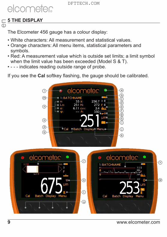
The Elcometer 456 gauge has a colour display:
• White characters: All measurement and statistical values.• Orange characters: All menu items, statistical parameters and
symbols.• Red: A measurement value which is outside set limits; a limit symbol
when the limit value has been exceeded (Model S & T).• - - - indicates reading outside range of probe.
If you see the Cal softkey flashing, the gauge should be calibrated.
www.elcometer.com9
en
R
j
b
a
c
f
m
l
n
o
p
q
I
h
k
s
u
r
t
w
v
d
e
g
DFTTECH.COM
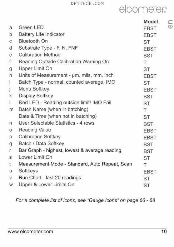
Modela Green LED EBSTb Battery Life Indicator EBSTc Bluetooth On STd Substrate Type - F, N, FNF EBSTe Calibration Method BSTf Reading Outside Calibration Warning On Tg Upper Limit On STh Units of Measurement - µm, mils, mm, inch EBSTi Batch Type - normal, counted average, IMO STj Menu Softkey EBSTk Display Softkey BSTl Red LED - Reading outside limit/ IMO Fail STm Batch Name (when in batching) T
Date & Time (when not in batching) STn User Selectable Statistics - 4 rows BSTo Reading Value EBSTp Calibration Softkey EBSTq Batch / Data Softkey BSTr Bar Graph - highest, lowest & average reading BSTs Lower Limit On STt Measurement Mode - Standard, Auto Repeat, Scan Tu Softkeys EBSTv Run Chart - last 20 readings STw Upper & Lower Limits On ST
For a complete list of icons, see “Gauge Icons” on page 66 - 68
www.elcometer.com 10
R
en
DFTTECH.COM

Reading display size (BST)
The character size of the measurement value on the display increases or decreases depending on the number of statistics that are displayed; or if a graph is displayed on the measurement screen . To maximise the reading size, either:
Ÿ reduce the number of statistical values that are displayed via Display/Statistics/Select Statistics, or
Ÿ display the reading only by checking the Display/Readings Only radio button.
www.elcometer.com11
en
R
DFTTECH.COM

6 THE GAUGE FEATURES
The Elcometer 456 coating thickness gauge has a number of easy to use features and functions to help the user be more efficient. These include:
Fast reading rate (EBST)
The Elcometer 456 is capable of taking greater than 70 accurate, repeatable and reproducible measurements every minute.
Easy to use menu structure in more than 30 languages (EBST)
Designed to be intuitive, the Elcometer 456 menus and calibration i ns t ruc t i ons a re ava i l ab le i n mu l t i p le l anguages v ia Menu/Setup/Language.
Bright colour screen (EBST)
Each gauge is supplied with a scratch and solvent resistant 2.4" (60mm) TFT colour screen which clearly displays the reading. The screen brightness can be adjusted manually (EBST) - via Menu/Setup/Screen Settings/Screen Brightness/Manual or automatically (BST) using the gauge’s ambient light sensor which can be switched on via Menu/Setup/Screen Settings/Screen Brightness/Auto.
Battery or USB Powered (EBST)
Each gauge can be powered either using 2 x AA lithium, alkaline or rechargeable batteries or by connecting the Elcometer 456 to your PC via a USB cable.
Two year gauge warranty (EBST)
The Elcometer 456 gauge is supplied with a 1 year warranty against manufacturing defects. To extend this warranty to 2 years, simply register your gauge via the elcometer.com website.
Emergency light mode (BST)
If all the lighting fails during an inspection in dark environments, the gauge is fitted with an emergency light feature - once selected (Menu/Emergency Light), the display turns bright white. To switch off this function either press and hold the Esc softkey or power off the gauge.
R
en
www.elcometer.com 12
DFTTECH.COM

Automatic rotating display (BST)
Using the internal accelerometer, the gauge will automatically rotate the display to allow you to easily read the thickness value in any orientation - 0°, 90°, 180° & 270°.
This function can be switched off by un-checking Menu/Setup/Screen Settings/Auto Display Rotation
Gauge firmware updates (BST)
Using Elcometer’s free data management software, ElcoMaster™, users can receive prompts when there is a gauge firmware update available for their model version.
When the Elcometer 456 is connected (via USB), to any computer with an internet connection and with ElcoMaster™ installed, ElcoMaster™ highlights the availability of a firmware update, identifies to the user the new features and guides the user through the gauge firmware update process.
Caution, before upgrading your gauge firmware, ensure that you have downloaded all inspection readings from the gauge. For more information regarding ElcoMaster™ see page 35 Downloading Data.
Bluetooth™ (ST) and USB Data output (BST)
Elcometer 456 gauges have the ability to transfer data via USB (BST) to a computer or wirelessly via Bluetooth™ (ST) technology to PC’s, PDA’s or mobile phones which are Bluetooth™ enabled using ElcoMaster™ or ElcoMaster™ Mobile Apps respectively.
B l u e t o o t h ™ d a t a o u t p u t c a n b e s w i t c h e d o n v i a Menu/Bluetooth/Enable Bluetooth. For more information regarding ElcoMaster™ see page 35 Downloading Data.
ElcoMaster™ Data output (BST)
Users can download data from any Elcometer gauge directly into ElcoMaster™ by connecting the gauge to the PC and following the on screen prompts.
www.elcometer.com13
en
R
DFTTECH.COM

Symbol / icon Model Description
η BST The number of readings taken
x BST Mean (average)
σ BST Standard deviation
Hi BST Highest reading taken
Lo BST Lowest reading taken
cv% BST Coefficient of variation; The COV is defined as the ratio of the standard deviation to the mean and is a normalised measure of dispersion - when comparing batches with widely different means, one should use the coefficient of variation for comparison instead of standard deviation (σ).
Once the data has been transferred to the computer, the user can produce professional reports in seconds. Data can also be transferred
®into programs, such as Excel , in a similar manner.
For more information regarding ElcoMaster™ see page 35 Downloading Data.
Counted Average (BST)
Users can define the number of individual gauge readings to be taken within a spot or measurement area using the Counted Average function. The gauge stores the average of the individual readings into memory. The individual readings within the counted average are not saved. Select Display/Statistics/Counted Average.
Counted Average is also available when in Batching (ST) - see BatchTypes on page 32.
On Screen Statistics (BST)
User selectable statistical and general measurement information can be displayed on the gauge. The information to be displayed can be selected and managed by selecting the Display softkey.
Ÿ Up to 8 statistics can be selected to be displayed on the reading screen via Display/Statistics/Select Statistics
Ÿ Ensure that Display/Readings & Selected Stats is also checked.
Ÿ To view all statistics select Display/Statistics/View All
The following statistical and general information can be displayed on your gauge:
R
en
www.elcometer.com 14
DFTTECH.COM

Symbol / icon Model Description
EIV BST Elcometer index value; Used to assess a coating’s overall quality. Ideal for use in the automotive refinishing industry. USA patent number US7606671.
NDFT ST Nominal dry film thickness; The target or specified dry film coating thickness value.
IMO PSPC ST International Maritime Organisation’s Performance Standard for Protective Coatings clearly defines the acceptance criteria for a coating. The Elcometer 456 can be quickly set up to display these parameters:
% > N ST The percentage of readings greater than or equal to the Nominal Dry Film Thickness Value.
90 % 100 ST The percentage of readings between 0.9 x NDFT and the NDFT.
90:10 ST Displays either pass (ü) or fail (X)
To pass the IMO PSPC 90/10 rule:
Ÿ At least 90% of all dry film thickness readings shall be greater than or equal to the NDFT value, and
Ÿ none of the remaining measurements shall be below 0.9 x NDFT
X! ST If all the measurements taken at any point are greater than 0.9 x NDFT, but less than 90% of the readings are greater than or equal to the NDFT, were the inspection to stop, then the IMO PSPC condition would be a fail. Statistically, however, were more measurements to be taken which were all greater than or equal to the NDFT, then there would come a time when the IMO PSPC condition returns to a pass. This is depicted by the “failing” icon - X!. For more information on the IMO PSPC see About IMO PSPC on page 74.
ST Low Limit
ST High Limit
ST Number of readings below the low limit
ST Number of readings above the high limit
User definable warning limits can be set. Once the reading exceeds the limit the gauge notifies the user by turning the reading and relevant limit icon red, flashing the red LED, and sounding the alarm beep. For more information see Limits on page 23.
www.elcometer.com15
en
R
n
n
DFTTECH.COM

Analogue Bar Graph (BST)
By selecting Display/Readings & Bar Graph the user can view an analogue representation of the current thickness value together with the highest (Hi), lowest (Lo) and average (x) reading. The graph is updated automatically when each reading is taken.
The values on the top left and right of the bar signify the measurement range using the thin calibration foil value less 10% and the thick calibration foil value plus 10%. If calibrated using the factory calibration, the probe scale range ±10% is used. If limits are set, the limit values ±10% are used and the relevant limit icon is displayed above the bar in the appropriate position.
With Limits: The current measurement is displayed as a white or red bar; white if within set limits, and red if outside set limits.
If below the lower limit, the left arrow head is also filled red and if above the upper limit, the right arrow head is filled red.
If the next measurement taken is within set limits, the left or right arrow outline will remain red to signify that the previous reading was outside set limits.
Without Limits: The current measurement is displayed as a white bar.
If outside the measurement range, the left or white arrow head is also filled white.
If the next measurement taken is within range, the left or right arrow outline will remain white to signify that the previous reading was outside range.
4 Users can choose to show Readings & Selected Stats (ST) - see On Screen Statistics on page 14, Readings & Run Chart (ST) - see Run Chart on page 17, Readings & Bar Graph (BST) or Readings Only (BST). Readings & Run Chart is only available when in Batching, it is not available in Standard (Immediate) Mode.
R
en
www.elcometer.com 16
DFTTECH.COM

Run Chart (ST)
By selecting Display/Readings & Run Chart the user can view a line trend graph of the last 20 measurements. The graph is updated automatically when each reading is taken.
Up to five horizontal axes are displayed representing different values / statistics as follows:
Ÿ Highest reading in the batch “ ”Ÿ Lowest reading in the batch “ ”
(for batches of more than one reading)
Ÿ Mean of readings in the batch “ ”(for batches of more than one reading)
Ÿ High limit for the batch “ ” (when enabled)
Ÿ Low limit for the batch “ ” (when enabled)
The readings are displayed as white or red points; white if a reading is within limits (or no limits have been set), and red if outside set limits.
When in Scan Mode (T) - see Measurement Modes on page 25, the Analogue Bar Graph is displayed on screen whilst scanning. This is replaced by the Run Chart when the scan is completed.
The highest and lowest reading for each scan is displayed on the run chart above and below the average value together with either a white or red vertical line; white if within set limits, and red if outside set limits.
The highest, average and lowest reading values for the last scan are also displayed under the run chart.
4 Users can choose to show Readings & Selected Stats (ST) - see On Screen Statistics on page 14, Readings & Run Chart (ST), Readings & Bar Graph (BST) - see Analogue Bar Graph on page 16 or Readings Only (BST). Readings & Run Chart is only available when in Batching, it is not available in Standard (Immediate) Mode.
Time and date (ST)
Once the appropriate time and date has been set (Menu/Setup/Time and Date), the user can display the time and date at the top of the Elcometer 456 display via Menu/Setup/Time and Date/Display Time and Date.
www.elcometer.com17
en
R
DFTTECH.COM

Ÿ The time format can be set to either the 12 hour or 24 hour clock via Menu/Setup/Time and Date/Set Format/Set Time Format
Ÿ The date format can be set to either dd/mm/yyyy, mm/dd/yyyy or yyyy/mm/dd via Menu/Setup/Time and Date/Set Format/Set Date Format
Please note that the time and date is replaced by the batch name when the gauge is in Batch mode.
When a batch is created, re-opened (or when the gauge is switched on whilst in batch mode) and when each reading is taken, the time and date details are stored within the batch - allowing the user to have an accurate record of when the measurements were taken. The time and date stamp for each reading is displayed on ElcoMaster™.
Multiple calibration methods (EBST)
Calibration adjustment is the process of setting the gauge to known values of thickness to ensure accuracy on different substrate types, shapes and surface finishes and is often referred to as simply the “calibration”.
The calibration of the gauge can be adjusted using several different methods for use in accordance with National and International Standards and the calibration adjustment method chosen depends on the condition of the substrate to be measured.
The calibration method is indicated on the screen by a symbol.
When using an FNF probe it must be calibrated in both the ferrous mode and in the non-ferrous mode to ensure accuracy of reading.
When using an Ultra/Scan probe in Scan Mode or Auto Repeat Mode (see Measurement Modes on page 25), it must be calibrated using either the Smooth or Rough/2 Point calibration method.
When switching between the Scale 1 and Scale 2 functions of the scale 2 probes (Menu/Setup/Probe) the Elcometer 456 should be re-calibrated to ensure accuracy across the appropriate measurement range.
www.elcometer.com 18
R
en
DFTTECH.COM
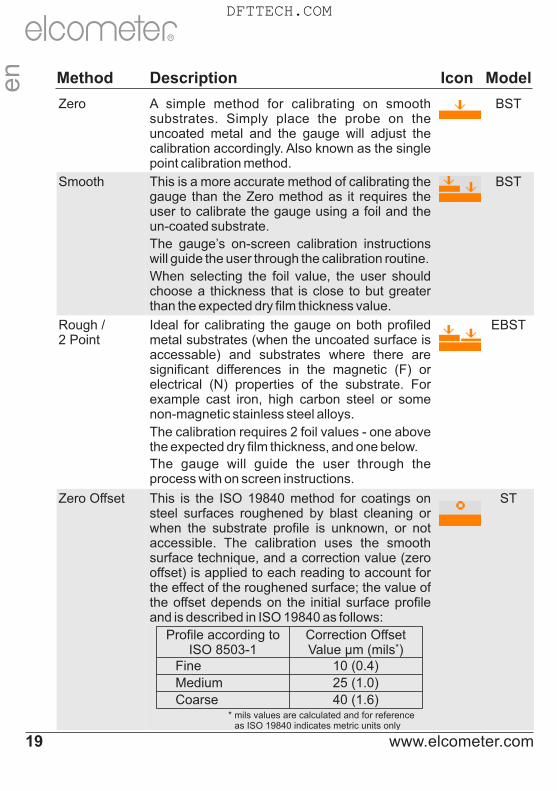
Method Description Icon Model
Zero A simple method for calibrating on smooth substrates. Simply place the probe on the uncoated metal and the gauge will adjust the calibration accordingly. Also known as the single point calibration method.
BST
Smooth This is a more accurate method of calibrating the gauge than the Zero method as it requires the user to calibrate the gauge using a foil and the un-coated substrate.
The gauge’s on-screen calibration instructions will guide the user through the calibration routine.
When selecting the foil value, the user should choose a thickness that is close to but greater than the expected dry film thickness value.
BST
Rough / 2 Point
Ideal for calibrating the gauge on both profiled metal substrates (when the uncoated surface is accessable) and substrates where there are significant differences in the magnetic (F) or electrical (N) properties of the substrate. For example cast iron, high carbon steel or some non-magnetic stainless steel alloys.
The calibration requires 2 foil values - one above the expected dry film thickness, and one below.
The gauge will guide the user through the process with on screen instructions.
EBST
Zero Offset This is the ISO 19840 method for coatings on steel surfaces roughened by blast cleaning or when the substrate profile is unknown, or not accessible. The calibration uses the smooth surface technique, and a correction value (zero offset) is applied to each reading to account for the effect of the roughened surface; the value of the offset depends on the initial surface profile and is described in ISO 19840 as follows:
ST
Profile according to ISO 8503-1
Correction Offset *Value µm (mils )
Fine 10 (0.4)
Medium 25 (1.0)
Coarse 40 (1.6)* mils values are calculated and for reference
as ISO 19840 indicates metric units only
www.elcometer.com19
en
R
DFTTECH.COM

Method Description Icon Model
Auto This is a calibration method unique to the Elcometer 456 and has been designed to simplify and speed up the calibration process for those users who are calibrating their gauge using the same foil values each time.
When the Auto calibration method is selected, the user is asked to pre-program the high and low foil values. The low foil value can be set to 0.0µm (0.0mils) for un-coated substrates.
Once these foil values have been set up, selecting the calibrate routine allows the user to simply place the probe on the high foil three times, followed by the low foil three times and the gauge is automatically calibrated - returning the user to the main reading screen - automatically.
ST
Factory By selecting this calibration method the Elcometer 456 returns the calibration to the gauge’s factory calibration settings.
The factory calibration method should only be used if there is no other means of calibration (e.g. lost foils, lack of access to substrate, etc.).
EBST
Pre-defined Calibration Methods (ST)
In addition to the standard calibration methods described on pages 16 - 18, the Elcometer 456 has a four pre-defined calibration methods which follow relevant standards.
These pre-defined calibration methods not only define the calibration routine to be used, but also set up the data collection method, as defined by the appropriate standard.
For this reason, pre-defined calibration methods can only be selected whilst the gauge is in batching mode. For more information on batching or data collection methods, see Batching on page 26.
www.elcometer.com 20
R
en
DFTTECH.COM

Method Description Icon Model
ISO Sets the calibration method to Zero Offset and sets the Counted Average to 5 - in accordance with ISO19840.
ST
SSPC PA2 Sets the calibration method to Rough/2 Point and sets the Counted Average to 3 - in accordance with SSPC PA2.
ST
Swedish Sets the calibration method to Rough/2 Point and sets the Counted Average to 5 - in accordance with Swedish standards.
ST
Australian Sets the calibration method to Zero Offset, and sets the Counted Average to 5 - in accordance with AS standards.
ST
For more information on how to calibrate the gauge, see Calibrating the Elcometer 456 on page 60.
User-programmable calibration memories (T)
The Elcometer 456 Model T allows users to store into memory up to three calibrations. Once a calibration memory has been saved, the user can select the calibration memory - without the need to re-calibrate the gauge.
Calibration memories are ideal for users who are inspecting coatings on various curvatures, blast profiles or coating thicknesses.
Using the gauge’s alpha-numeric function, users can re-name the calibration memory to suit the calibration setting.
For example:
Ÿ A user who is inspecting coatings on two blast profiles - shot and grit could store calibrations into Cal Memory 1 and Cal Memory 2 and re-name them ‘Shot’ and ‘Grit’ respectively
Ÿ A user measuring on flat and curved surfaces could store the calibrations into ‘Flat cal’ and ‘Curved cal’.
Ÿ Thick and thin coating thickness calibrations can also be saved and renamed ‘320µm’ and ‘120µm’
For more information on re-naming calibration memories, see Alpha-numeric naming of batches and cal memories on page 27.
www.elcometer.com21
en
R
DFTTECH.COM

Outside calibration warning (T)
In order to achieve the most accurate reading the gauge should be calibrated to the substrate type, shape and profile using the appropriate calibration method together with foil values that are slightly above the target dry film thickness.
When using the gauge’s calibration memories, or batching (see Batching on page 26) different calibration foil values may be used in each calibration.
value if using Rough/ 2 point) the gauge reading alarm sounds a triple beep and the Calibration Check icon (located above the units symbol) turns red. This feature does not amend or tag any reading, it is a real time warning feature only.
Calibration lock (BST)
To avoid accidental amendments to the calibration settings switching on the Cal/Calibration Lock feature’ locks’ the user from undertaking any changes to the calibration without first un-checking the Cal/Calibration Lock feature.
When the Calibration Lock is enabled, users can still test the calibration via Cal/Test Calibration but will be unable to validate or re-calibrate the gauge.
The calibration can also be locked using a PIN Code, see page 63 for more information.
Once the Outside calibration warning function Cal/Calibration Check has been switched on, if a coating thickness reading is taken which is more than 10% above the foil value (and 10% below the lower foil
www.elcometer.com 22
R
en
DFTTECH.COM

Gauge Memory (BST)
The Elcometer 456 versions are supplied with a varying level of memory:
Model E: No memory
Model B: The Model B gauge’s ‘rolling statistics’ provides accurate statistical values for all measurements taken since the statistics were last cleared (Display/Clear Statistics). The last 5 readings, however, can be displayed by pressing the Data softkey.
Model S: 1,500 readings can be stored into the gauge’s memory
Model T: A total of 150,000 readings can be stored into the gauge’s memory either in a single batch or in up to 2,500 batches (see Batching on page 26). Each batch can be individually named and can have its own unique calibration.
Limits (ST)
During the inspection process coatings can often have specified minimum and/or maximum thickness values.
For example, coatings that have been applied too thinly over a surface profile can lead to rust spots appearing on the peaks of the profile. Similarly too thick a coating can also lead to premature coating failures.
Users can program upper and/or lower warning limits into the Elcometer 456 gauge by selecting Menu/Set Limits/Set Upper or Menu/Set Limits/Set Lower.
To switch the limits on, the user should ensure that the Enable Limits radio button is checked.
Ÿ When an Upper Limit has been set up and enabled the “ ” icon is displayed.
Ÿ When a Lower Limit has been set up and enabled the “ ” icon is displayed.
Ÿ If both Upper and Lower limits have been set up and enabled then the two icons are displayed together as “ ”.
www.elcometer.com23
en
R
DFTTECH.COM

When the Elcometer 456 gauge takes a reading which is outside the set limits the following occurs:
Ÿ The Red LED flashes
Ÿ The reading is displayed in red
Ÿ The alarm beeps 3 times
Ÿ The associated limit icon turns red
In addition, the number of readings above limit (or below limit as applicable) statistic is incremented. In Batching, the reading is tagged with either the high or low icon as appropriate. For more information see Batching on page 26.
To switch off a particular limit go to Menu/Set Limits/Set Upper or Menu/Set Limits/Set Lower and set the limit value to Off using the up and down soft keys.
The programmed limit values can be displayed on the reading screen via Display/Statsitics/Select Statistics and checking the appropriate radio button. The maximum number of statistics that can be displayed on the reading screen at the same time is 8.
If a low limit has been set up, the upper limit value cannot be lower than the pre-set lower limit.
Individual limits can also be set up for each batch on Model T gauges. For more information see Batching on page 26.
Gauge Welcome Screen (BST)
Users can adjust the start up screen on their Elcometer 456 gauges via the ElcoMaster™ software - see page 64 for more information.
www.elcometer.com 24
R
en
DFTTECH.COM

7 MEASUREMENT MODES (ST)
7.1 The Elcometer 456 gauges have four measurement modes:
Standard (Immediate) Mode (ST): Where readings are taken, rolling statistics calculated (and displayed), but individual values are not stored in the memory.
Scan Mode (T): Specifically designed for use with Elcometer 456 Ultra/Scan Probes - see page 79, when Scan Mode is selected, the user can slide the Ultra/Scan Probe over the entire surface area. As the probe is lifted off the surface the average (x), lowest (Lo) and highest (Hi) coating thickness values are displayed. When Batching, each set of three readings can be shown on a Run Chart - see page 17 and stored into memory.
Scan Mode with Hold (T): As above but allows the probe to be lifted off the surface for a maximum of 1.5 seconds and replaced without starting a new set of readings - allowing the user to avoid holes, weld seams, etc. in the substrate without affecting the measurement results.
Auto Repeat Mode (T): When the probe is placed onto the coated substrate in Auto Repeat Mode, the gauge automatically takes readings at a rate of 140 per minute until the probe is removed from the substrate. When Batching, each individual reading is stored into the memory.
7.2 NAVSEA MODE (T): Displays the reading to the nearest 1mil (1µm) above 10mils (254µm) and 0.1mil (0.1µm) below 10mils (254µm). To select NAVSEA mode, press Menu/Setup/NAVSEA or Batch/New Batch/NAVSEA.
4 Scan and Auto Repeat Modes are only available on Elcometer 456 Model T separate gauges. The probe end cap must be fitted to the Ultra/Scan Probe when used in these modes to avoid damage to the probe tip. Use in these modes without the cap will invalidate the probe warranty.
Hi, x & Lo
www.elcometer.com25
en
R
1, 2, .......n
DFTTECH.COM

8 BATCHING (ST)
Readings can be stored into memory in batches. Batches allow the user to collate readings for easier analysis of large structures or complex assemblies. Elcometer 456 Model T gauges can store a total of 150,000 readings in up to 2,500 batches, the Model S has one batch of up to 1,500 readings.
The Elcometer 456 has the following batching functions:
Ÿ Create a new batch (ST); Batch/New BatchŸ Open an existing batch (ST); Batch/Open Existing BatchŸ Rename an existing batch (T); Batch/Edit Batch/Rename BatchŸ Copy a batch - including all calibration and limit setups (T);
Batch/Copy BatchŸ Clear all the readings within the batch - but leaving all calibration
and limit setups (ST); Batch/Edit Batch/Clear BatchŸ Review the readings, statistics, calibration, batch information (ST)
and a graph of the readings (T); Batch/Review BatchŸ Delete a Batch (ST), or all batches (T), entirely from the gauge;
Batch/Edit Batch/Delete Batch Ÿ Delete the last reading entirely or delete the reading, but mark the
reading as deleted in the batch memory (ST) - Batch/Deleted Reading/Delete With Tag and Batch/Deleted Reading/Delete Without Tag respectively.
Creating a new batch (T)
When using batching for the first time, or when you wish to open a new batch, press Batch/New Batch. The user can now:
Ÿ Open the batch and take readings; Batch/New Batch/Open Batch 1Ÿ Rename the batch - before opening it via Batch/New
Batch/Rename Batch 1. (See Alpha numeric naming Batches & Cal Memories on page 27)
www.elcometer.com 26
R
en
DFTTECH.COM

Ÿ Select the appropriate calibration method - Batch/New Batch/ Batch Calibration (see Multiple calibration methods on page 18)
Ÿ Choose the type of batch (normal, counted average or IMO PSPC) before opening it via Batch/New Batch/Batch Type (see Batch Types on page 32)
Ÿ Set up specific batch limits via Batch/New Batch/Batch Limits (see Limits on page 23)
Ÿ Set up a fixed batch size via Batch/New Batch/Fixed Batch Size (see Fixed Batch Size on page 33)
Once all the batch settings have been created, press Batch/New Batch/Open Batch 1 - where ‘Batch 1' may now be a re-named as required.
Alpha numeric naming batches & cal memories (T)
When in batching - or setting up a calibration memory (see Calibration Memories on page 21) - the user can rename the batch or cal memory to a more appropriate name.
When a new batch is created, the gauge automatically names it ‘Batch n’ - where ‘n’ is the next unused batch number; e.g. Batch 1, Batch 2, Batch 3, etc.
To rename a batch either:
Ÿ when creating a new batch press Batch/New Batch/Rename Batch 1; or
Ÿ press Batch/Edit Batch/Rename Batch and select the Batch to be renamed from the list of existing batches
To rename a calibration memory:
Ÿ press Cal/Cal Memory 1; Cal/Cal Memory 2 or Cal/Cal Memory 3
Ÿ then select Rename Cal Memory n (where n=1, 2 or 3)
This then opens up the renaming procedure to enable the user to rename the batch or cal memory.
www.elcometer.com27
R
en
DFTTECH.COM

The current name of the batch (or cal memory) is in white in the middle of the display with a yellow ‘cursor’ icon to the right of the name.
Using the left arrow, right arrow and Select softkeys, the user can rename the batch or cal memory as required.
The yellow, raised character or function is the item that will be ‘chosen’ by pressing the Select soft key.
Pressing the Esc softkey at any time cancels the whole operation without making any changes to the original name.
To store the re-named ‘name’ highlight OK and press the Select softkey.
Character Action
OKStores the name and returns the user to the previous screen
Deletes the last character of the name
A, B, C... Selects the character A, B or C, etc.
Inserts a space
123Changes the selection characters to: 1 2 3 4 5 6 7 8 9 0
ABCChanges the selection characters to: A B C D E F G H J K L M N O P Q R S T U V W X Y Z
ÀÇüChanges the selection characters to: ÀÁÂÃÄÅÆÇÈÉÊËÌÍÎÏÐÑÒÓÔÕÖÙÚÛÜÝÞßµm
$%&Changes the selection characters to: ! # ’ £ $ € % & * [ ] _ - + / \ < > : @ ; ”
www.elcometer.com 28
en
R
DFTTECH.COM

Opening an existing batch (ST)
By selecting Batch/Open Existing Batch on the Model T, the user will find a list of all the batches that have already been created, together with the number of readings stored in each batch.
To open a particular batch use the up and down arrow soft keys and select the appropriate batch.
The Elcometer 456 will return the gauge to the main reading screen and the selected batch name will be shown at the top of the display (together with a unique gauge batch id number - allowing no two batches to have exactly the same name).
As the Model S only has one batch, the batch will open automatically.
Copying an existing batch (T)
By selecting Batch/Copy Batch the user will find a list of all the batches that have already been created, together with the number of readings stored in each batch.
To copy a particular batch use the up and down arrow soft keys and select the appropriate batch.
The Elcometer 456 will then copy all the batch settings - calibration and foil values, batch type, cal method, warning limits, and the batch name - and then ask the user whether they wish to rename the batch.
Pressing the Yes softkey the user will then be asked to rename the batch using the renaming procedure described on page 27.
Pressing the No softkey (or pressing the Esc softkey whilst in the renaming procedure) will make the Elcometer 456 copy the existing batch name to the new batch - thereby two batches will have the same batch name.
Copying a batch does not copy the individual readings within that batch.
Clearing an existing batch (ST)
By Selecting Batch/Edit Batch/Clear Batch on the Model T, the user will find a list of all the batches that have already been created, together with the number of readings stored in each batch.
To clear a particular batch’s individual readings only, use the up and down arrow soft keys and select the appropriate batch.
www.elcometer.com29
en
R
DFTTECH.COM

As the Model S only has one batch, it is selected automatically.After a request for confirmation, the gauge will clear the readings from the selected batch and return the gauge to the list of batches (T) or the Batch Menu (S). To clear another batch (T), repeat the procedure. To return the gauge back to the previous menu, press the Back softkey. The user can clear all batches via Batch/Edit Batch/Clear Batch/All Batches (T).
Reviewing an existing batch (ST)By selecting Batch/Review Batch the user will find a list of all the batches that have already been created, together with the number of readings stored in each batch.To review a particular batch use the up and down arrow soft keys and select the appropriate batch. As the Model S only has one batch, it is selected automatically.The Elcometer 456 will then open up the Review Batch menu, allowing the user to:Ÿ Review the statistics of the batchŸ Review the batch information, including:
Ÿ the date and time the batch was createdŸ the batch type - normal, counted average or IMO PSPCŸ the probe type and serial number used to take the readingsŸ the calibration method - smooth, rough/2 point, etc.Ÿ the batch limits (if set)
Ÿ Review the batch’s calibration information, including:Ÿ the date and time the batch was last calibrated or verifiedŸ the substrate type (or types if using an FNF probe)Ÿ the probe type and serial number Ÿ the calibration method - smooth, rough/2 point etc.Ÿ the foil values used in the calibration
Ÿ Review the individual readings. The Elcometer 456 displays:Ÿ the readings in numerical order, the first reading is at the topŸ the substrate, time and date of measurementŸ icons indicating a reading above “ ” or below “ ” the limitŸ deleted readings icon “ ” is displayed if “Delete With Tag”
selected, (see page 26 for more information).Ÿ Review a graph of the individual readings (T), see page 31.
www.elcometer.com 30
en
R
DFTTECH.COM

Batch Readings Graph (T)
By selecting Batch/Review Batch/Batch Graph the user can review all readings in the selected batch as a graph.
Up to five horizontal axes can be displayed representing different values / statistics as follows:
Ÿ Highest reading in the batch “ ”Ÿ Lowest reading in the batch “ ”
(for batches of more than one reading)
Ÿ Mean of readings in the batch “ ”(for batches of more than one reading)
Ÿ High limit for the batch “ ”(when enabled)
Ÿ Low limit for the batch “ ”(when enabled)
The readings are displayed as white or red vertical bars; white if a reading is within limits (or no limits have been set), and red if outside set limits.If there are more readings in the batch than can be displayed on a single screen, multiple readings will be combined into one bar. Should a single reading within the ‘combined bar’ be outside the enabled limits, the whole bar will be red.
Pressing the Zoom+ softkey, allows each individual reading to be displayed, thereby showing the individual readings outside the limits.
When zoomed in, the graph will always display the first 25 readings. Pressing the ç softkey will display the last 25 readings taken. Subsequent presses of the ç softkey will scroll backwards, pressing the è softkey will scroll forwards through the readings, 25 readings at a time.
Pressing the Zoom- softkey returns to the original overview graph of all readings in the batch.
To return the gauge to the Batch Review menu, press the Back softkey.
www.elcometer.com31
en
R
DFTTECH.COM

Delete an existing batch (ST)
By Selecting Batch/Edit Batch/Delete Batch the user will find a list of all the batches that have already been created (T) or a single batch (S), together with the number of readings stored in each batch.
To delete a particular batch’s individual readings only use the up and down arrow soft keys and select the appropriate batch.
After a request for confirmation, the gauge will delete the selected batch and return the gauge to the list of batches.
To delete another batch, repeat the procedure, to return the gauge back to the previous menu, press the Back softkey.
The user can delete all batches from the gauge by selecting Batch/Edit Batch/Delete Batch/All Batches (T).
Exit Batching (ST)
To stop using the Batching Mode and return to the Immediate mode select Batch/Exit Batching.
Batch Types (ST)
When saving readings into a batch you have a choice of how the readings are managed within the gauge:
Normal: Each reading is saved into memory. Press Batch/New Batch/Batch Type and then select Normal.
The batch type can only be changed when creating a new batch.
Counted Average: The average of a predefined number of readings is saved into memory. For example a counted average of 3 means:
The average of [Reading 1 + Reading 2 + Reading 3] is stored as the first measurement saved in the memory.
Likewise the average of readings 4 - 6 are stored as the second measurement in the memory, etc.
The individual readings within the counted average (1.2.3, 4.5.6, etc.) are not saved.
Press Batch/New Batch/Batch Type and then select Counted Average.
The batch type can only be changed when creating a new batch.
www.elcometer.com 32
en
R
DFTTECH.COM

The Elcometer 456 then asks the user to set the counted average value. Using the up and down arrow softkeys, set the counted average from 2 - 99 and press the Ok softkey.
This returns the user to the previous screen. Press the Back softkey to continue setting up the new batch as required before opening the new batch.
If Statistics are displayed whilst measuring using the counted average function (CAF) when taking the readings used to calculate the CAF measurement, the gauge will display the rolling statistical calculations of the individual readings until all the readings that go into calculating the CAF measurement are taken. At this point the statistics then display the values of the stored CAF measurements.
IMO PSPC: If you are inspecting coating thickness according to the International Maritime Organisations Performance Standard for Protective Coating, selecting the IMO PSPC batch type and then subsequently opening the batch, the gauge automatically:
• Asks the user to confirm the NDFT (nominal dry film thickness) value
• Sets the statistics to display the relevant IMO PSPC values• Identifies the batch as an IMO PSPC batch for further analysis in
the ElcoMaster™ data management software
For more information on the IMO PSPC see page 74. For more information on ElcoMaster™ see page 35.
Fixed Batch Size (T)
When creating a new batch, by selecting Batch/New Batch and checking the Fixed Batch Size radio button, users can pre-define the number of readings that are to be stored into the batch (between 1 and 255) using the up and down arrow softkeys.
Once the batch has been opened and readings are being taken, the Elcometer 456 will notify the user when the fixed batch size is complete and ask if another batch is to be opened.
If the user selects No, then the gauge closes the batch and exits batching - returning the gauge to the Standard (Immediate) mode.
www.elcometer.com33
en
R
DFTTECH.COM

If the user selects Yes, then the gauge automatically:
Ÿ Appends a ‘_1' to the original batch nameŸ Opens a new batch - copying all the batch setup and calibration
informationŸ The new batch is named as the original batch, with a ‘_2'
For example:
Ÿ A fixed batch is created and named “Component A”.
Ÿ When the batch is full, a new fixed batch ‘Component A_2’ is created
Ÿ ‘Component A’ becomes ‘Component A_1’
Appending the batch name in this way allows the user to quickly identify - or link - similar batches together.
Once a fixed batch size batch has been filled, no additional readings can be added to that batch; a partially completed fixed batch size batch, however, can be re-opened and completed at a later date.
To continue a batch link, press Batch/Open Existing Batch and select the last batch in the link. If the batch is full, the gauge will prompt the user to open a new batch before continuing. If the batch is partially complete the user can complete the batch before continuing to a new batch.
When downloading linked batches into ElcoMaster™; the original batch name will be displayed (Component A in the above example). Selecting this batch name will download all linked batches into ElcoMaster™ at the same time. For more information on downloading batches see page 44.
Note: Once a fixed batch size batch has been created and data has been stored into the memory, the user cannot rename the batch name within the gauge. The batch name can be amended using the ElcoMaster™ software.
www.elcometer.com 34
en
R
DFTTECH.COM

9 DOWNLOADING DATA USING ELCOMASTER™ (BST)
Measurements from the Elcometer 456 Models B, S and T can be downloaded to a computer using the ElcoMaster™ software (supplied with Model S and T gauges, downloadable from the Elcometer website for Model B gauges), or the older versions of ElcoMaster™.
This instruction book explains how users can download data using ElcoMaster™.
Installing ElcoMaster™
To install ElcoMaster™ insert the supplied mini-CD into your CD ROM drive. The software will automatically begin the install procedure.
If it does not, or you have downloaded the software from the Elcometer website, run the SetupElcoMaster2.exe file.
The ElcoMaster™ Setup Wizard will then begin.
Follow the on screen wizard
www.elcometer.com35
en
R
DFTTECH.COM

It is important to read the License Agreement carefully and if the terms are acceptable, select the ‘I accept this agreement’ radio button and click ‘Next >’
ElcoMaster™ will automatically select a default destination location for the software to be installed.
Click the ‘Browse...’ button to select an alternate file location.
Click ‘Next >’ to continue
Choose any additional tasks, by selecting the appropriate check box and press ‘Next >’ to continue
www.elcometer.com 36
en
R
DFTTECH.COM

The ElcoMaster™ wizard now provides a list of the settings that have been selected.
Click ‘Install’ to undertake the installation or ‘< Back’ to review or alter any settings.
ElcoMaster™ will now install.
Press ‘Finish’ to exit Setup.
Upgrading data from older version of ElcoMaster™
ElcoMaster™ is fitted with an internal database upgrade facility which will automatically check to see if there are any original ElcoMaster™ database files and ask if the user would like to upgrade the data to the new ElcoMaster™ format.
Upgrading can occur at any time by selecting Menu/Import/Import E l coMas te r 1 .x Da ta and selecting the relevant database file.
www.elcometer.com37
en
R
DFTTECH.COM

The ElcoMaster™ Software
ElcoMaster™ is a simple - yet powerful - data management software solution that has been designed to allow users to generate professional reports in seconds - with the minimum of fuss.
It has three operating modes; Excel Link, Standard and Advanced Mode. ElcoMaster™ is set to Standard Mode on first install.
Across the top of the software is a Menu button, ‘Action Tabs’ and an expand arrow.
Pressing the Menu button opens up a drop down list of options:
Ÿ Help : Provides Elcometer contact details and information about ElcoMaster™.
Ÿ Update : Provides users with:Ÿ the ability to update the ElcoMaster™ software
to the latest release - connection to the internet is required for this function.
Ÿ the ability to upgrade the firmware of the: Ÿ Elcometer 224 Digital Surface Profile
Gauge (Model B & T)Ÿ Elcometer 456 Digital Coating Thickness
Gauge (Model B, S & T)Ÿ Elcometer 130 Salt Contamination Meter
(Model S & T)
www.elcometer.com 38
en
R
Menu Button Action Tabs Expand Arrow
DFTTECH.COM

www.elcometer.com39
en
R
Ÿ Import: Allows users to import a database from an earlier version of ElcoMaster™- version 1.x (not applicable to the new Elcometer 130)
Ÿ Exit: Allows users to shut down the software
The Action Tabs available depend on the operating mode in use as follows:
Excel Link Mode
Ÿ Settings : Allows users to adjust:
Ÿ The language of ElcoMaster™Ÿ The units of measurement by gauge typeŸ Customise the default reports to include a user
logo or image, together with footer informationŸ Adjust the normal distribution type for the
histogram chart Ÿ Alter the colour settings of the user interfaceŸ The text file separator used when exporting filesŸ Select an alternate location to store the databaseŸ Enable or disable the auto update option (where
access to the internet is prohibited).
Ÿ Download: Allows users to connect all their Elcometer gauges ®via USB, Bluetooth , or RS 232 where appropriate.
Standard Mode: All the features of Excel Link Mode plus;
Ÿ View: Allows users to:
Ÿ View measurement data, gauge information, measurement statistics, set limits, add notes and labels and view photographs and other documents
Ÿ Print, email or PDF standard reportsŸ Export data to Excel or other software packages
as requiredŸ Archive (and restore) old data
DFTTECH.COM

Ÿ Saved Reports: Once a user has generated a PDF report from within the View action tab, the report is automatically saved within the Saved Reports action tab - for reference and review.
Advanced Mode: All the features of Excel Link and Standard Mode plus;
Ÿ Design custom reports
Ÿ View data in standard forms - predefined within the Design Report action tab or by Elcometer.
Ÿ Design a collection template to guide inspectors where, and in which order, readings should be taken - see page 46 for further details.
Users can switch between operating modes at any time by pressing the Expand Arrow and selecting the mode required.
en
R
www.elcometer.com 40
DFTTECH.COM
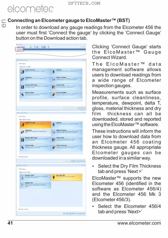
Clicking ‘Connect Gauge’ starts t h e E l c o M a s t e r ™ G a u g e Connect Wizard.
T h e E l c o M a s t e r ™ d a t a management software allows users to download readings from a wide range of Elcometer inspection gauges.
Measurements such as surface profile, surface cleanliness, temperature, dewpoint, delta T, gloss, material thickness and dry f i lm thickness can al l be downloaded, stored and reported using the ElcoMaster™ software.
These instructions will inform the user how to download data from an Elcometer 456 coat ing thickness gauge. All appropriate Elcometer gauges can be downloaded in a similar way.
Ÿ Select the Dry Film Thickness tab and press ‘Next >’
ElcoMaster™ supports the new Elcometer 456 (identified in the software as Elcometer 456/4) and the Elcometer 456 Mk 3 (Elcometer 456/3).
Ÿ Select the Elcometer 456/4 tab and press ‘Next>’
Connecting an Elcometer gauge to ElcoMaster™ (BST)
In order to download any gauge readings from the Elcometer 456 the user must first ‘Connect the gauge’ by clicking the ‘Connect Gauge’ button on the Download action tab.
www.elcometer.com41
en
R
DFTTECH.COM

Ÿ S e l e c t t h e a p p r o p r i a t e connection method for the gauge
Elcometer 456 gauges come supplied with Bluetooth (Models S & T) and USB (Models B, S & T) data output.
Users can purchase a USB B l u e t o o t h A d a p t o r f r o m E lcomete r (Par t number T99924797) which will provide a Bluetooth solution to computers without internal bluetooth fitted.
If ElcoMaster™ is installed onto a computer without Bluetooth c a p a b i l i t y, h o w e v e r, t h e Bluetooth tab is greyed out (as displayed in top image).
Ÿ S e l e c t t h e a p p r o p r i a t e connection method
Ÿ Switch on the Elcometer 456
Ÿ Connect the USB cable or make sure that Bluetooth is switched on in the gauge via Menu/Bluetooth/Enable Bluetooth (S & T)
Ÿ Bluetooth users should return their gauge to the main r e a d i n g s c r e e n b e f o r e continuing
Ÿ Press ‘Next >’
Ÿ A f t e r a s c r e e n p r o m p t ElcoMaster™ will search for and list all Elcometer 456 gauges.
en
R
www.elcometer.com 42
DFTTECH.COM

Each coating thickness gauge connected is now listed.
Ÿ Select the appropriate gauge and press ‘Next >’
If connecting via Bluetooth, the gauges are identified using the Bluetooth ID - which can be seen o n t h e b o t t o m o f t h e Menu/Bluetooth screen.
Connecting via Bluetooth now requires the gauge to be ‘Paired’ by keying in the gauge’s unique Bluetooth PIN Code. This code can be found on the bottom of the Menu/Bluetooth screen.
Ÿ Type in the Bluetooth PIN Code and press ‘Next >’
(See Section 10 on page 56 for information on connecting via Bluetooth to a mobile device using ElcoMaster™ Mobile Apps.)
ElcoMaster™ will now validate the connection, press Finish when complete.
The gauge is now connected and ElcoMaster™ will return the user to the Download action tab, and display the connected gauge.
The same gauge can be connected by more than one method. Repeat the ‘Connect Gauge’ and follow the on screen prompts.
By clicking on the Edit button, users can Delete the gauge from ElcoMaster™, name the gauge by a more familiar identification (Enter a User ID) or set up the gauge power up display screen (Change the Welcome screen). See Changing the Welcome Screen on page 64.
en
R
www.elcometer.com43
DFTTECH.COM

The Download Wizard will now guide the user through the simple download readings process.
ElcoMaster™ allows users to download their gauge readings:
Ÿ Directly into ElcoMaster™
Ÿ D i r e c t l y i n t o a n E x c e l Spreadsheet , bypass ing ElcoMaster™
Ÿ into a text file for use in other software programs, or
Ÿ into a CQATK XML file
Ÿ Select the appropriate option
Ÿ Select or create a new project folder as required (ElcoMaster™ Batch File users)
Users wishing to export directly into Excel will also be asked to select a single or multiple spreadsheet option. Single; all batches selected will be downloaded into a single spreadsheet. Multiple; each batch will be downloaded into a separate spreadsheet tab.
Ÿ Select one or more individual batches or click on ‘All Files’ and press ‘Next >’
Downloading Data from the Elcometer 456 (ST)
Once the gauge has been connected to ElcoMaster™ (see pages 41-43), switch on your gauge and click the ‘Download from Gauge’ button for the relevant gauge and connection method.
When downloading data into ElcoMaster™ (as opposed to directly into a spreadsheet or a text file), downloaded data is stored in Projects - allowing users to clearly identify inspections.
en
R
www.elcometer.com 44
DFTTECH.COM

The User will be asked to select a project name from the list. Alternatively the user can create a New Project name.
Ÿ Select or create a new project and press ‘Next >’
To download readings from the gauge:
Ÿ Select a single or multiple batches from the list or click on ‘All Files’ as required, then press ‘Next >’
Ÿ Select or create a new folder to save the gauge’s data to
In some cases users may have re-used an existing batch name in the gauge. The user should now chose either to select:
Ÿ Rename Duplicate Files
Ÿ Rename All Files, or
Ÿ Overwrite Existing Files
Ÿ Select as required and press ‘Next >’
The selected batches will now download. Once the da ta download has been completed, the user can check the ‘View Files’ box and click ‘Finish’.
Alternatively, click ‘Finish’ and select the ‘View Action Tab’
en
R
www.elcometer.com45
DFTTECH.COM

Viewing Data in ElcoMaster™
ElcoMaster™ not only allows users to view and analyse data from a wide range of Elcometer gauges, but also allows users to manually input data as required.
This instruction book provides a brief summary of some of the features of ElcoMaster™, however users should read the ElcoMaster™ help file for a complete guide.
Data Tree Command Tabs Template Tabs
Live Reading Tab Measurement Data Window Graph Window
en
R
www.elcometer.com 46
DFTTECH.COM

By selecting the View Action Tab, users can instantly see their data. The View Action Tab can be broken down into 6 distinct areas:
Ÿ Data Tree Batches can be stored within folders ( ) in unique Project files ( ).
By clicking on the Project filename, users can then complete unique project tags and batch tags as required.
Each batch of data is identified by the type of inspection:
Climate Batch
Surface Profile Batch
Surface Cleanliness Batch
Dry Film Thickness Batch
Material / Ultrasonic NDT Batch
Clicking the computer mouse’s right button over a file or folder provides the user with the following functions:
Ÿ New: Allows users to:Ÿ create a new Project ( )Ÿ create a new Folder ( )Ÿ import an Image ( )Ÿ import a PDF Document ( )Ÿ create a new batch type
Ÿ Cut, Copy & Paste: Cut, copy & paste inspection files and folders
into other files or folders within the data tree.
Ÿ Delete, rename & move to: Allows delete, rename or move a file
Ÿ Combine & Split:
Combine batches of the same type or split a batch into equal sizes or of equal time
Ÿ Archive & Restore: Archive and restore inspection data
Ÿ Print, PDF, Email & Export: Print, generate a PDF or export to Excel or a tab
separated text file; the selected batch report
en
R
www.elcometer.com47
DFTTECH.COM

Ÿ Command Tabs
There are 6 command tabs, which are the key functions required by the user.
Ÿ New: Allows users to:Ÿ create a new Project ( )Ÿ create a new Folder ( )Ÿ import an Image ( )Ÿ import a PDF, .edf, .txt. Document ( )Ÿ create a new batch type
Ÿ Move to: Moves the selected items to a different folder or
to a different page
Ÿ Print: Prints a report of the selected items
Ÿ PDF: Generates a PDF report of the selected items
Ÿ Email: Generates a PDF report of the selected items
and attaches it to an email
Ÿ Export:Ÿ Allows the user to export the selected items into
Excel or as a text or CQATK XML filee
n
R
www.elcometer.com 48
DFTTECH.COM

Ÿ Template Tabs & Graph Window
There are currently 2 graphs within ElcoMaster™; individuals and histogram. Clicking a template tab displays the relevant graph in the Graph Window
When the Individuals Graph is displaying climate data, additional tabs appear on the right hand side, allowing the user to select a measurement to view from the following:
RH: Relative Humidity
Ts: SurfaceTemperature
Ta: Air Temperature
Td: Dewpoint Temperature
TΔ: Delta T, (Ts-Td)
Tdb: Dry Bulb Temperature
Twb: Wet bulb Temperature
SH: Specific Humidity
Right mouse click on the individuals graph allows users to select the x-axis value between:
Date & Time Relative Time (seconds)
Reading Number Relative Time (minutes)
Left clicking and dragging the mouse across the individuals chart allows users to zoom in on a specific area of the graph. The zoom can be reset by clicking on the icon.
en
R
www.elcometer.com49
DFTTECH.COM

Ÿ Measurement Data Window
The measurement data window provides the user with a range of information under 7 tabs:
Ÿ Details Provides useful information about the measurement gauge,
serial number, batch name, date the batch was created, date and time of the first and last reading, etc.
Ÿ Statistics Provides the user with a wide range of statisitical
calculations - mean, minimum and maximum reading, standard deviation, ±3σ, coefficient of variation, relevant information regarding the IMO PSPC analysis (coating thickness gauge readings only).
Users can display the values on the graph by clicking the ( ) icon and selecting a colour.Ÿ Measurements Displays all the individual readings. Users can alter the
display order (Date & Time, Relative Time (seconds), Relative Time (minutes) and Reading Number) by clicking on the column title.
Individual measurements can be excluded/ included by right clicking on the specific measurement within the table. Measurements can also be amended by overtyping the relevant reading.
Comments can be added to any measurement by clicking on, and then typing into, the relevant cell within the comments column.
Ÿ Limits Shows any limits that were used whilst taking the readings or
allows users to apply limits. When set, measurements outside the limits are highlighted within the measurement tab.
Users can display the values on the graph by clicking the ( ) icon and selecting a colour.
en
R
www.elcometer.com 50
DFTTECH.COM
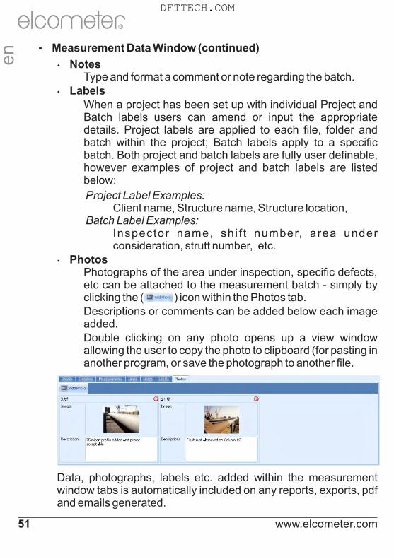
Ÿ Measurement Data Window (continued)
Ÿ Notes Type and format a comment or note regarding the batch.Ÿ Labels When a project has been set up with individual Project and
Batch labels users can amend or input the appropriate details. Project labels are applied to each file, folder and batch within the project; Batch labels apply to a specific batch. Both project and batch labels are fully user definable, however examples of project and batch labels are listed below:
Project Label Examples: Client name, Structure name, Structure location, Batch Label Examples: Inspector name, shi f t number, area under
consideration, strutt number, etc.Ÿ Photos Photographs of the area under inspection, specific defects,
etc can be attached to the measurement batch - simply by clicking the ( ) icon within the Photos tab.
Descriptions or comments can be added below each image added.
Double clicking on any photo opens up a view window allowing the user to copy the photo to clipboard (for pasting in another program, or save the photograph to another file.
Data, photographs, labels etc. added within the measurement window tabs is automatically included on any reports, exports, pdf and emails generated.
en
R
www.elcometer.com51
DFTTECH.COM

Ÿ Live Gauge Readings (BST)
ElcoMaster™ allows users to transfer data from a gauge as the readings are taken, to be stored in a batch within ElcoMaster™.
Live gauge readings can be recorded via Bluetooth (ST) or USB (BST) connections
Once the gauge has been connected to ElcoMaster™ (see pages 41-43), switch on your gauge and click the ‘Live Readings’ button on the View Action Tab
Ÿ Select the appropriate batch (or create a new batch) for the readings to be recorded into
ElcoMaster™ will now open up the Live Readings display, and ask the user to ‘ Connect Gauge’
Ÿ Click on the Connect Gauge
Ÿ Select a gauge from the list
Ÿ Select the relevant connection me thod ( i f more than one connection method has been set up (see pages 41-43)
ElcoMaster™ will then link with the selected gauge and, when ready display the gauge information within the Live Readings window.
Ÿ At any time the user can select a different batch to change where the next reading is taken.
Ÿ Click the button or switch of the gauge to disconnect
en
R
www.elcometer.com 52
DFTTECH.COM

Ÿ Click on the Design Collect tab and select an existing template or click ‘New Design’
When creating a new design you will be asked to:- Enter a name and description
- Select the Batch Type; Prof i le, Material Thickness, DFT or Surface Cleanliness
- Add the required image to collect readings against
- Specify the number of readings to be collected
- Enter relevant Limits
- Request a prompt to begin the next set of readings or begin automatically
- Choose to create a new batch for each set of readings or create a single batch with multiple reading sets
Ÿ Click ‘Finish’ to begin the design
To design the ‘collect’ image sequence, simply click and hold each 'reading' circle in turn, drag onto the image where readings are to be taken and adjust the size accordingly.
Once complete click ‘Save’ and click the 'X' button in the top right to close the design window.
Ÿ Design Collect
The ‘Design Collect’ function allows users to set up a collection template to guide Inspectors where, and in which order, readings should be taken. This image can be used as a collection guide in
‡ElcoMaster™ or transferred to an Android mobile phone or tablet using ElcoMaster™ for Android™, see pages 55 - 56.
‡ To use Design Collect, switch ElcoMaster™ to Advanced Mode by clicking on the Expand Arrow, and selecting ‘Start Advanced Mode’.
www.elcometer.com53
en
R
DFTTECH.COM

Using a Collect Design
Ÿ Select the ‘View’ tab
Ÿ Select a folder or project and click the ‘New’ button
Ÿ Move the cursor to relevant batch type, an additional window will appear, select the required Collect Design
A new batch will be created. Unlike standard batches it will have an additional tab with the same name as the Collect Design, click on this to show your design. To begin collection,
Ÿ Click on ‘Connect Gauge’ in the ‘Live Readings’ window
aŸ Select a gauge from the list
Ÿ Select the relevant connection method
ElcoMaster™ will link the selected gauge and, when ready, display the gauge information within the Live Readings window.
Once connected, green arrows will flash around the first ‘reading’ circle to measure. When a measurement is taken, the ‘reading’ circle will change to
bshow the measured value , and the green arrows will move to the next reading.
a The gauge must be connected to ElcoMaster™ before it will appear in the list, see pages 41 - 43.b The ‘reading’ circle will be green if the measurement is within set limits and red, if outside limits.
en
R
www.elcometer.com 54
DFTTECH.COM

10 ELCOMASTER MOBILE APPS (ST)
Ideal when out in the field or on-site, live readings can be stored directly onto a mobile device and saved into batches. Inspection data can be transferred from mobile to PC for further analysis and reporting.
ElcoMaster™ Mobile Apps features include:
Ÿ Store live readings directly on to a mobile device and save into batches.
Ÿ Download batches straight to a mobile device allowing data analysis immediately on site.
Ÿ Transfer inspection data to PC for further analysis and reporting.
Ÿ Analyse data via sequential readings, statistics, charts & histograms or on images.
Ÿ Download collection images created using the 'Design Collect' function within ElcoMaster™ to indicate where and in which order readings should be taken.
Ÿ Take photographs and add them to batch readings at the click of a button.
Ÿ Map readings on to maps, photographs or diagrams.
en
R
www.elcometer.com55
DFTTECH.COM

en
R
www.elcometer.com 56
Connecting via Bluetooth to a Mobile Device
To use ElcoMaster™ Mobile Apps, the Elcometer 456 gauge must be 'paired' with mobile device via Bluetooth:
1. Switch on the Elcometer 456 and ensure that Bluetooth is enabled via Menu/Bluetooth/Enable Bluetooth. Return the gauge to the main reading screen before continuing.
2. Switch on the mobile device and enable Bluetooth (usually via 'Settings' – refer to the operating instructions for the mobile device).
3. The mobile device will search for and list all Elcometer 456 gauges with Bluetooth enabled. Each gauge is identified as “E-456/4“ followed by the serial number.
4. Select the Elcometer 456 gauge required. The mobile device now will attempt to 'pair' with the selected gauge.
5. A 'Bluetooth' pairing request will appear on both the mobile device and gauge. Accept the pairing request on both.
The mobile device and Elcometer 456 gauge are now 'paired'.
Compatible with smart phones and tablets running Android 2.1 or above. To install, download via www.elcometer.com or using the Google Play™ Store app, and follow the on screen instructions.
Made for iPhone 6 Plus, iPhone 6, iPhone 5s, iPhone 5c, iPhone 5, iPhone 4s, iPhone 4, iPad Air 2, iPad mini 3, iPad Air, iPad mini 2, iPad (3rd and 4th generation), iPad mini, iPad 2, and iPod touch (4th and 5th generation). To install, download via www.elcometer.com or the App Store, and follow the on screen instructions.
DFTTECH.COM

11 CLOUD COMPUTING WITH ELCOMASTER (ST)
ElcoMaster™ is now compatible with Cloud Computing.
Ÿ Create a Cloud account via a Cloud service provider e.g. Dropbox, Google Drive™, Skydrive or your own cloud based FTP server.
Ÿ All approved users of the cloud account will have instant access to all inspection data in real time.
Ÿ Data can be accessed by authorised users via secure log-in from any computer or mobile device anywhere in the world via
®Bluetooth , USB, WiFI or 3G/4G.
Ÿ Using the ElcoMaster™ instant messaging feature, job instructions can be sent or stored in specific job files.
Ÿ Wherever you are in the world, ElcoMaster™ Mobile allows you to instantly upload to the cloud via 3G/4G or WiFi.
en
R
www.elcometer.com57
DFTTECH.COM

12 GETTING THE MOST OUT OF ELCOMASTER
ElcoMaster™ has been designed to be a very intuitive method of developing professional reports, it is however extremely versatile. Here are just a few ways ElcoMaster™ can be used in the day-to-day activities of a coating professional.
1. Gauge to PC to Excel
Transferring inspection data straight into Microsoft Excel via Bluetooth® or USB is simple and easy.
4. Upload to a cloud for real time analysis anywhere
Using ElcoMaster™ Mobile App you can upload inspection data, photos, notes and GPS coordinates direct to a Cloud account of your choice via 3G/4G or WiFi.
All data is instantly visible to other approved users of the account - through a secure log-in on any computer or mobile device anywhere in the world.
2. Gauge to PC data transfer into ElcoMaster™
®Using Bluetooth or USB, ElcoMaster™ transfers inspection data in seconds, archiving data and generating reports at the click of a button.
3. ElcoMaster™ Mobile App for immediate data transfer from site to office
Transfer inspection data straight to ®
mobiles and tablets via Bluetooth when on site for instant analysis, then e-mail them back to the office for storing, review and QA reporting.
5. Seamlessly link multiple sites or production lines
ElcoMaster™ gives you real time quality control monitoring from multiple inspection projects in any location. You can compare and combine inspection data from different production lines or different locations, to produce specific Project Inspection Reports quickly and easily.
en
R
www.elcometer.com 58
DFTTECH.COM

12 GETTING THE MOST OUT OF ELCOMASTER
Real time collaboration for multi-site projectsWhen working with manufacturers of sub-assemblies across the globe ElcoMaster™ can collate all inspection data from each site, assembly line and project into one shared location. Contractors can then:Ÿ Accept or reject parts before
shipment from sub-assembly plants.Ÿ Combine all data from sub
assembly and final assembly inspection to generate Project Inspection Reports for quality management, both during and after completion of the project.
Ÿ Have real time in progress visibility across the whole project, no matter where the sub-assembly manufacturing is in the world.
Ÿ Have multi-site collaboration, real time dialogue and decision making to improve efficiency and quality throughout the production process.
Real time communicationFeaturing instant messaging the ElcoMaster™ Mobile App lets you add messages to inspection data, projects and files, allowing you to immediately discuss key points with your colleagues, managers or clients, send work instructions and store messages within the project file.
Your data - your choice - your controlElcoMaster™ allows you to decide which Cloud service provider to use. It is your data, it is secure as only approved users can have access, no third parties can see your data.
ElcoMaster™ Mobile App is compatible with a range of cloud service providers and FTP servers including: Google Drive, FTP Server, Dropbox.
6. Real time collaboration for multi-site projectsen
R
www.elcometer.com59
DFTTECH.COM
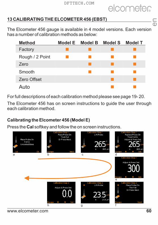
13 CALIBRATING THE ELCOMETER 456 (EBST)
The Elcometer 456 gauge is available in 4 model versions. Each version has a number of calibration methods as below:
For full descriptions of each calibration method please see page 19- 20.
The Elcometer 456 has on screen instructions to guide the user through each calibration method.
Method Model E Model B Model S Model T
Factory ■ ■ ■ ■
Rough / 2 Point ■ ■ ■ ■
Zero ■ ■ ■
Smooth ■ ■ ■
Zero Offset ■ ■
Auto ■ ■
Calibrating the Elcometer 456 (Model E)
Press the Cal softkey and follow the on screen instructions.
a b c d
e
h g f
en
R
www.elcometer.com 60
DFTTECH.COM

To calibrate the Elcometer 456 Model E on rough surfaces:
Ÿ Select two foil values - one above the target dry film thickness value (thick) and one below (thin)
Ÿ Follow the on screen instructions
Ÿ more than one reading can be taken on each foil value - the average of the readings is displayed (screens c and g on page 60).
Ÿ To calibrate the Elcometer 456 Model E on smooth surfaces:
Ÿ Select a foil value which is above the target dry film thickness value (thick) and the uncoated base substrate (thin).
Ÿ When the gauge instructs the user to place the gauge onto the thin foil (calibration step 2), place the probe on the uncoated base and adjust the thickness value to 0.0µm (mils)
To calibrate the Elcometer 456 Model E using the Factory calibration:
Ÿ Select either Menu/Reset/Metric Gauge or Menu/Reset/Imperial Gauge.
Taking multiple readings on each foil will increase the accuracy of the calibration.
Calibrating the Elcometer 456 (BST)
Ÿ Press the Cal softkey to open the Calibration menu
Ÿ As the Elcometer 456 Model B, S and T have multiple calibration methods;
Ÿ if the Calibration Method icon displayed is as required, press the Select softkey and follow the on screen instructions
Ÿ the user can amend the calibration method, by selecting the appropriate method from within the Cal/Cal Method menu and press the Select softkey before selecting Calibrate from the Calibration menu
en
R
www.elcometer.com61
DFTTECH.COM
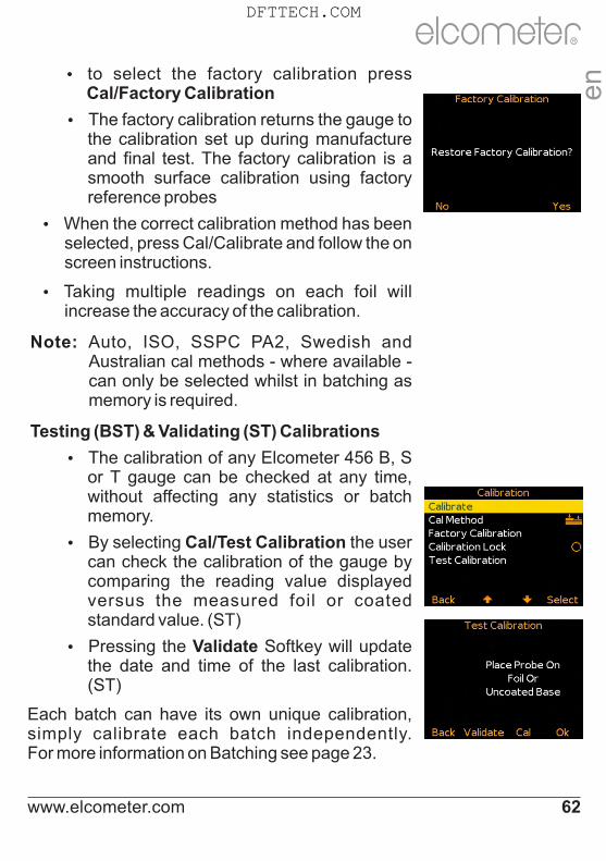
Ÿ to select the factory calibration press Cal/Factory Calibration
Ÿ The factory calibration returns the gauge to the calibration set up during manufacture and final test. The factory calibration is a smooth surface calibration using factory reference probes
Ÿ When the correct calibration method has been selected, press Cal/Calibrate and follow the on screen instructions.
Ÿ Taking multiple readings on each foil will increase the accuracy of the calibration.
Note: Auto, ISO, SSPC PA2, Swedish and Australian cal methods - where available - can only be selected whilst in batching as memory is required.
Testing (BST) & Validating (ST) Calibrations
Ÿ The calibration of any Elcometer 456 B, S or T gauge can be checked at any time, without affecting any statistics or batch memory.
Ÿ By selecting Cal/Test Calibration the user can check the calibration of the gauge by comparing the reading value displayed versus the measured foil or coated standard value. (ST)
Ÿ Pressing the Validate Softkey will update the date and time of the last calibration. (ST)
Each batch can have its own unique calibration, simply calibrate each batch independently. For more information on Batching see page 23.
en
R
www.elcometer.com 62
DFTTECH.COM
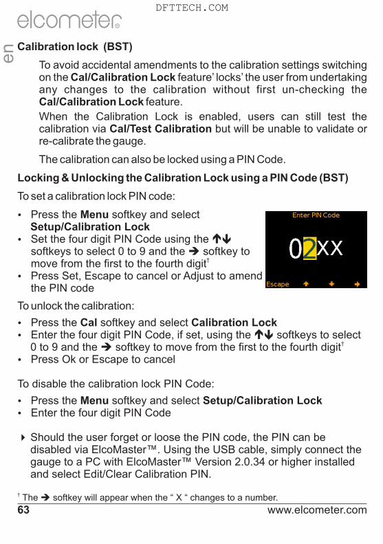
Calibration lock (BST)
To avoid accidental amendments to the calibration settings switching on the Cal/Calibration Lock feature’ locks’ the user from undertaking any changes to the calibration without first un-checking the Cal/Calibration Lock feature.
When the Calibration Lock is enabled, users can still test the calibration via Cal/Test Calibration but will be unable to validate or re-calibrate the gauge.
The calibration can also be locked using a PIN Code.
Locking & Unlocking the Calibration Lock using a PIN Code (BST)
To unlock the calibration:
Ÿ Press the Cal softkey and select Calibration LockéŸ Enter the four digit PIN Code, if set, using the softkeys to select ê
†0 to 9 and the è softkey to move from the first to the fourth digit
Ÿ Press Ok or Escape to cancel
To disable the calibration lock PIN Code:
Ÿ Press the Menu softkey and select Setup/Calibration LockŸ Enter the four digit PIN Code
4Should the user forget or loose the PIN code, the PIN can be disabled via ElcoMaster™. Using the USB cable, simply connect the gauge to a PC with ElcoMaster™ Version 2.0.34 or higher installed and select Edit/Clear Calibration PIN.
† The è softkey will appear when the “ X “ changes to a number.
To set a calibration lock PIN code:
Ÿ Press the Menu softkey and selectSetup/Calibration Lock
éŸ Set the four digit PIN Code using the ê�softkeys to select 0 to 9 and the è softkey to
†move from the first to the fourth digitŸ Press Set, Escape to cancel or Adjust to amend
the PIN code
en
R
www.elcometer.com63
DFTTECH.COM

14 CHANGING THE WELCOME SCREEN (BST)
Each time the Elcometer 456 gauge is switched on, the Elcometer logo is displayed. Users can add their own logo, image or identification details as required via ElcoMaster™.
Once the gauge has been connected to ElcoMaster™ (see pages 41-43), to add a user welcome screen
Ÿ Switch on your gauge
Ÿ Select the Download Action Tab
Ÿ Click the ‘Edit’ button on the right hand side of the appropriate gauge
Ÿ Select ‘Change Welcome Screen’ from the drop down menu
Ÿ Select the required image, and or add user specific text and press ‘Next >’
Ÿ Select ‘Stretch Image’ or ‘Centre Image’ as required and press ‘Next >’
Ÿ Select the appropriate connection method and press ‘Next >’
ElcoMaster™ will now download the selected image into the gauge. This may take some time.
en
R
www.elcometer.com 64
DFTTECH.COM

15 GAUGE FIRMWARE UPDATES (BST)
Each time the Elcometer 456 gauge is connected to ElcoMaster™ (see pages 41-43); if the computer has access to the internet, ElcoMaster™ automatically checks to see if there are any gauge firmware updates for the connected gauge.
ElcoMaster™ will inform the user when there are any firmware updates available for the connected gauge by displaying the ‘Update Gauge’ button.
Please note that users can update the gauge firmware via a USB connection only .
Clicking the ‘Update Gauge’ button will display a list of the ‘Fixes’ in all the updates that have been released since the gauge’s last upgrade.
Ÿ Press ‘Next >’ to continue.
Warning - updating the gauge firmware will result in all readings, batches, statistics and calibrations being deleted. The gauge will also be returned to the factory default settings.
Ÿ Press ‘Nex t > ’ t o commence downloading the latest firmware to the Elcometer 456
Warning - Do not switch off the computer or disconnect the gauge during the gauge upgrade.
Typical firmware updates include gauge enhancements, amendments, language updates, etc. Users cannot upgrade a Model B to a Model S for example, nor can a ferrous gauge be upgraded to a dual ferrous/non-ferrous gauge.
en
R
www.elcometer.com65
DFTTECH.COM

16 GAUGE ICONS & ERROR CODES (EBST)
Icon Description Model
Number of Readings BST
Mean (average) BST
Standard Deviation BST
Highest Reading BST
Lowest Reading BST
Coefficient of Variation BST
Elcometer Index Value (EIV) BST
NDFT Value (Nominal Dry Film Thickness) ST
Percentage of readings greater than or equal to the NDFT Value ST
Percentage of readings between 0.9 x NDFT and the NDFT value ST
90/10 Rule Pass ST
90/10 Rule Fail: 90% of readings are greater than the NDFT value ST
90/10 Rule Fail: At least one measurement is below 0.9 x NDFT. (If a number between 1 and 10 is displayed, insufficient measurements have been taken to be statistically valid)
ST
Counted Average (when not in Batching) BST
High and Low Limit Set ST
Low Limit Set ST
High Limit Set ST
Number of readings above Limit ST
Number of readings below Limit ST
en
R
www.elcometer.com 66
DFTTECH.COM

Icon Description Model
Zero Calibration Method BST
Smooth Surface Calibration Method BST
Rough/ 2 Point Calibration Method EBST
Zero Offset Calibration Method ST
Auto Calibration Method ST
ISO 19840 Calibration Method ST
SSPC PA2 Calibration Method ST
Swedish Standards Calibration Method ST
Australian Standards Calibration Method ST
Calibration Check T
Reading outside Calibration T
Calibration Lock BST
Calibration
Icon Description Model
Low Limit Set: Reading outside Low Limit ST
High Limit Set: Reading outside High Limit ST
Low & High Limit Set: Reading outside Low Limit ST
Low & High Limit Set: Reading outside High Limit ST
en
R
www.elcometer.com67
DFTTECH.COM

Icon Description Model
Auto Repeat Mode T
Scan Mode T
Scan Mode with Hold T
Icon Description Model
Bluetooth Not Connected ST
Bluetooth Connected ST
USB Connected BST
Ferrous Probe on Ferrous Substrate EBST
Non-Ferrous Probe on Non-Ferrous Substrate BST
Dual FNF Probe on Ferrous Substrate EBST
Dual FNF Probe on Non-Ferrous Substrate EBST
Battery Life Indicator EBST
Replace Batteries EBST
User Selectable Feature: Switched Off EBST
User Selectable Feature: Switched On EBST
Beep Volume Setting EBST
General
Icon Description Model
Batch Type: Normal ST
Batch Type: Counted Average ST
Batch Type: IMO PSPC ST
Deleted Reading - Tagged ST
Batching
en
R
www.elcometer.com 68
Measurement Modes
DFTTECH.COM

Message Cause / Action
#1 - Probe Probe to gauge communication failure.Integral Gauges: Contact Elcometer.Separate Gauges: Remove probe and refit. If error persists, contact Elcometer.
#2 - Probe Corrupt data output from probe.Integral Gauges: Contact Elcometer.Separate Gauges: Replace probe. If error persists, contact Elcometer.
#3 - Probe Internal Error - contact Elcometer.
Probe Unsupported No probe connected. Connect probe.Probe is Dual FNF but gauge is ferrous or non-ferrous only or Mk 3 probe is being used with a Mk 4 gauge.Use correct probe.
Probe Changed Probe has been changed during a calibration procedures. Calibration adjustment required.
Unstable Reading External electromagnetic interference or gauge is faulty.Isolate from electromagnetic interference. If error persists, contact Elcometer.
Value Too Large Calculated value is too large to be displayed. Contact Elcometer.
Calibration Error Incorrect calibration calculation. Re-calibrate. If error persists, contact Elcometer.
Bluetooth PC Reply Bluetooth link working at limit of its range. PC is busy running other applications. Interference. PC application doesn’t send replies. Move gauge closer to PC. Shutdown other applications. Remove source of interference. If error persists, contact Elcometer.
Error - EEPROM Write Gauge EEPROM communication error.If problem persists, EEPROM is faulty.
Error Codes
Under certain conditions, the gauge will display error messages. These message are cleared by pressing any key. The cause of the error should be corrected before proceeding.
en
R
www.elcometer.com69
DFTTECH.COM

Tim
e a
nd
Da
teS
et T
ime
Se
t Da
teS
et F
orm
at
Dis
pla
y T
ime
an
d D
ate
17 GAUGE MENU STRUCTURES (EBST)
Please find below a simplified diagram of each Elcometer 456 model’s menu structures.
Elcometer 456 Model T
Me
asu
rem
en
t M
od
eS
tan
da
rd M
od
eA
uto
Re
pe
at M
od
eS
can
Mo
de
Sca
n M
od
e W
ith H
old
Se
tup
Un
itsL
an
gu
ag
eT
ime
an
d D
ate
Be
ep
Vo
lum
eS
cre
en
Se
ttin
gs
Pro
be
Me
asu
rem
en
t Mo
de
Ga
ug
e A
uto
Off
Ca
libra
tion
Lo
ckN
AV
SE
AS
cre
en
Se
ttin
gs
Scr
ee
n B
rig
htn
ess
Scr
ee
n T
ime
ou
t A
uto
Dis
pla
y R
ota
tion
Op
en
ing
Scr
ee
n
Se
t L
imits
En
ab
le L
imits
Se
t Up
pe
rS
et L
ow
er
Se
t ND
FT
Blu
eto
oth
En
ab
le B
lue
too
thB
lue
too
th ID
xxxx
xxB
lue
too
th C
od
e
xxxx
xx
A
I
Ab
ou
tG
au
ge
In
form
atio
nP
rob
e In
form
atio
nC
on
tact
Le
ga
l
Ba
tch
Lim
itsE
na
ble
Lim
itsS
et U
pp
er
Se
t Lo
we
rS
et N
DF
T
Ba
tch
Typ
eN
orm
al
Co
un
ted
Ave
rag
eIM
O P
SP
CBa
tch
Ca
libra
tion
Ca
libra
teC
al M
eth
od
Use
Ca
l Me
mo
ry 1
Use
Ca
l Me
mo
ry 2
Use
Ca
l Me
mo
ry 3
De
lete
d R
ea
din
gD
ele
te W
ith T
ag
De
lete
With
ou
t Ta
g
Ne
w B
atc
hO
pe
n B
atc
h 1
Re
na
me
Ba
tch
1B
atc
h C
alib
ratio
nB
atc
h T
ype
Ba
tch
Lim
itsF
ixe
d B
atc
h S
ize
NA
VS
EA
Menu
Dele
te L
ast
Readin
gS
etu
pS
et L
imits
Blu
eto
oth
About
Rese
tE
merg
ency
Lig
ht
Calib
ratio
nC
alib
rate
Cal M
eth
od
Cal M
em
ory
1C
al M
em
ory
2C
al M
em
ory
3F
act
ory
Calib
ratio
nC
alib
ratio
n L
ock
Test
Calib
ratio
nC
alib
ratio
n C
heck
Batc
hM
em
ory
Fre
eN
ew
Batc
hO
pen E
xist
ing B
atc
hE
xit B
atc
hin
gE
dit
Batc
hC
opy
Batc
hR
evi
ew
Batc
hD
ele
ted R
eadin
g
Dis
pla
yC
lear S
tatis
tics
Readin
gs
Only
Readin
gs
& S
ele
cted S
tats
Readin
gs
& R
un C
hart
Readin
gs
& B
ar G
raph
Batc
h G
raph
Sta
tistic
s
○
Revi
ew
Batc
hB
atc
h 1
Sta
tistic
sB
atc
h In
form
atio
nC
alib
ratio
n In
form
atio
nR
eadin
gs
Batc
h G
raph
Ca
libra
tion
Lo
ckE
na
ble
PIN
Un
itsµ
mm
mm
ilsin
ch
Sta
tistic
sC
lear
Sta
tistic
sV
iew
Sele
cted
Vie
w A
llS
ele
ct S
tatis
tics
Counte
d A
vera
ge
Ed
it B
atc
hR
en
am
e B
atc
hC
lea
r B
atc
hD
ele
te B
atc
h
†P
rob
eA
uto
FN
FF
err
ou
s F
No
n F
err
ou
s N
Pro
be
Sw
itch
On
†P
rob
eF
err
ou
s F
1F
err
ou
s F
2
Le
ga
lP
ate
nts
Le
ga
l No
tice
sR
eg
ula
tory
Ca
l Me
tho
dZ
ero
Sm
oo
thR
ou
gh
/ 2
Po
int
Ze
ro O
ffse
tA
uto
ISO
SS
PC
PA
2S
we
dis
hA
ust
ralia
n
○ ○○ ○ ○ ○
Cal M
eth
od
Zero
Sm
ooth
Rough / 2
Poin
tZ
ero
Offse
tA
uto
Cal M
em
ory
nS
ave
d h
h:m
m d
d/m
m/y
y
Sele
ctC
alib
rate
Cal M
eth
od
Test
Calib
ratio
nR
enam
e C
al M
em
ory
nV
iew
Calib
ratio
n D
ata
Cle
ar
Cal M
em
ory
n
where
n =
1, 2,
or
3
○ ○
○○
Sele
ct S
tatis
tics
All
PS
PC
Valu
es
Num
ber
of R
eadin
gs
Mean
Low
est
Readin
gH
ighest
Readin
gS
tandard
Devi
atio
n
C
oeffic
ient of V
ariatio
n
Low
Lim
it V
alu
eN
um
ber
Belo
w L
imit
Hig
h L
imit
Valu
eN
um
ber
Above
Lim
itE
lcom
ete
r In
dex
Valu
eN
DF
T V
alu
e%
>=
ND
FT
% 9
0-1
00%
ND
FT
IMO
90:1
0 P
ass
/Fail
○ ○ ○ ○ ○ ○ ○ ○ ○ ○ ○ ○ ○ ○ ○ ○
○ ○ ○ ○ ○ ○ ○ ○ ○○ ○ ○ ○ ○ ○ ○ ○ ○ ○ ○ ○ ○ ○ ○ ○ ○ ○ ○ ○ ○ ○ ○○
† Menu displayed is dependent on
the probe connected
en
R
www.elcometer.com 70
Re
gu
lato
ry
QD
ID
x
xxxx
x
x
xxxx
x
x
xxxx
x
x
xxxx
x
○○
DFTTECH.COM

17 GAUGE MENU STRUCTURES CONTINUED (EBST)
Elcometer 456 Model S
Tim
e a
nd
Da
teS
et T
ime
Se
t Da
teS
et F
orm
at
Dis
pla
y T
ime
an
d D
ate
Se
tup
Un
itsL
an
gu
ag
eT
ime
an
d D
ate
Be
ep
Vo
lum
eS
cre
en
Se
ttin
gs
Pro
be
Ga
ug
e A
uto
Off
Ca
libra
tion
Lo
ck
Scr
ee
n S
ettin
gs
Scr
ee
n B
rig
htn
ess
Scr
ee
n T
ime
ou
t A
uto
Dis
pla
y R
ota
tion
Op
en
ing
Scr
ee
n
Se
t L
imits
En
ab
le L
imits
Se
t Up
pe
rS
et L
ow
er
Se
t ND
FT
Blu
eto
oth
En
ab
le B
lue
too
thB
lue
too
th ID
xxxx
xxB
lue
too
th C
od
e
xxxx
xx
A
I
Ab
ou
tG
au
ge
In
form
atio
nP
rob
e In
form
atio
nC
on
tact
Le
ga
l
Ba
tch
Typ
eN
orm
al
Co
un
ted
Ave
rag
eIM
O P
SP
CBa
tch
Ca
libra
tion
Ca
libra
teC
al M
eth
od
De
lete
d R
ea
din
gD
ele
te W
ith T
ag
De
lete
With
ou
t Ta
g
Ne
w B
atc
hO
pe
n B
atc
h 1
Ba
tch
Ca
libra
tion
Ba
tch
Typ
e
Menu
Dele
te L
ast
Readin
gS
etu
pS
et L
imits
Blu
eto
oth
About
Rese
tE
merg
ency
Lig
ht
Calib
ratio
nC
alib
rate
Cal M
eth
od
Fact
ory
Calib
ratio
nC
alib
ratio
n L
ock
Test
Calib
ratio
nBatc
hM
em
ory
Fre
eN
ew
Batc
hO
pen E
xist
ing B
atc
hE
xit B
atc
hin
gE
dit
Batc
hR
evi
ew
Batc
hD
ele
ted R
eadin
g
Dis
pla
yC
lear S
tatis
tics
Readin
gs
Only
Readin
gs
& S
ele
cted S
tats
Readin
gs
& R
un C
hart
Readin
gs
& B
ar G
raph
Sta
tistic
s
○
Re
vie
w B
atc
hB
atc
h 1
Sta
tistic
sB
atc
h In
form
atio
nC
alib
ratio
n In
form
atio
nR
ea
din
gs
Ca
libra
tion
Lo
ckE
na
ble
PIN
Un
itsµ
mm
mm
ilsin
ch
Sta
tistic
sC
lear
Sta
tistic
sV
iew
Sele
cted
Vie
w A
llS
ele
ct S
tatis
tics
Counte
d A
vera
ge
Ed
it B
atc
hC
lea
r B
atc
hD
ele
te B
atc
h
†P
rob
eA
uto
FN
FF
err
ou
s F
No
n F
err
ou
s N
Pro
be
Sw
itch
On
†P
rob
eF
err
ou
s F
1F
err
ou
s F
2
Le
ga
lP
ate
nts
Le
ga
l No
tice
sR
eg
ula
tory
Ca
l Me
tho
dZ
ero
Sm
oo
thR
ou
gh
/ 2
Po
int
Ze
ro O
ffse
tA
uto
ISO
SS
PC
PA
2S
we
dis
hA
ust
ralia
n
○ ○
○ ○ ○ ○
Cal M
eth
od
Zero
Sm
ooth
Rough / 2
Poin
tZ
ero
Offse
tA
uto
○ ○
○
Sele
ct S
tatis
tics
All
PS
PC
Valu
es
Num
ber
of R
eadin
gs
M
ean
Low
est
Readin
gH
ighest
Readin
gS
tandard
Devi
atio
n
C
oeffic
ient of V
ariatio
n
Low
Lim
it V
alu
eN
um
ber
Belo
w L
imit
Hig
h L
imit
Valu
eN
um
ber
Above
Lim
itE
lcom
ete
r In
dex
Valu
eN
DF
T V
alu
e%
>=
ND
FT
% 9
0-1
00%
ND
FT
IMO
90:1
0 P
ass
/Fail
○ ○ ○ ○ ○ ○ ○ ○ ○ ○ ○ ○ ○ ○ ○ ○
○ ○ ○ ○ ○ ○ ○ ○ ○○ ○ ○ ○ ○ ○ ○ ○ ○ ○ ○ ○ ○ ○ ○ ○
† Menu displayed is dependent on
the probe connected
en
R
www.elcometer.com71
Re
gu
lato
ry
QD
ID
x
xxxx
x
x
xxxx
x
x
xxxx
x
x
xxxx
x
DFTTECH.COM
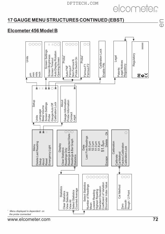
17 GAUGE MENU STRUCTURES CONTINUED (EBST)
Elcometer 456 Model B
Dis
pla
yC
lear S
tatis
tics
Readin
gs
Only
Readin
gs
& S
ele
cted S
tats
Readin
gs
& B
ar G
raph
Sta
tistic
s
†P
robe
Auto
FN
FF
err
ous
FN
on F
err
ous
NP
robe S
witc
h O
n
†P
robe
Ferr
ous
F1
Ferr
ous
F2
○ ○ ○ ○ ○ ○
Setu
pU
nits
Language
Beep V
olu
me
Scr
een S
ett
ings
Pro
be
Gauge A
uto
Off
Calib
ratio
n L
ock
Scr
een S
ett
ings
Scr
een B
rightn
ess
Scr
een T
imeout
Auto
Dis
pla
y R
ota
tion
Openin
g S
creen
About
Gauge I
nfo
rmatio
nP
robe I
nfo
rmatio
nC
onta
ctLegal
Cal M
eth
od
Zero
Sm
ooth
Rough / 2
Poin
t
○ ○ ○○ ○ ○ ○ ○ ○ ○
Menu
Dele
te L
ast
Readin
gS
etu
pA
bout
Rese
tE
merg
ency
Lig
ht
Calib
ratio
nC
alib
rate
Cal M
eth
od
Fact
ory
Calib
ratio
nC
alib
ratio
n L
ock
○
Data
Last
Fiv
e R
eadin
gs
5
0.5
µm
5
2.3
µm
5
1.0
µm
51.8
µm
5
1.5
µm
Esc
ape D
ele
te O
k○ ○ ○
○○ ○
Sele
ct S
tatis
tics
Num
ber
of R
eadin
gs
Mean
Low
est
Readin
gH
ighest
Readin
gS
tandard
Devi
atio
n
Coeffic
ient of V
ariatio
n
Elc
om
ete
r In
dex
Valu
e
Calib
ratio
n L
ock
Enable
PIN
Units
µm
mm
mils
inch
○ ○ ○ ○
Legal
Pate
nts
Legal N
otic
es
Regula
tory
Sta
tistic
sC
lear
Sta
tistic
sV
iew
Sele
cted
Vie
w A
llS
ele
ct S
tatis
tics
Counte
d A
vera
ge
† Menu displayed is dependent on
the probe connected
en
R
www.elcometer.com 72
Regula
tory
xx
xxx
DFTTECH.COM

17 GAUGE MENU STRUCTURES CONTINUED (EBST)
Elcometer 456 Model E
SetupUnitsLanguageBeep VolumeScreen SettingsProbe Switch On
Unitsµmmmmilsinch
AboutGauge InformationProbe InformationContactLegal
MenuSetupAboutReset
Calibration
Pressing the Cal Softkeystarts the calibration process
Screen SettingsScreen BrightnessScreen Timeout
○
LegalPatentsLegal NoticesRegulatory
en
R
www.elcometer.com73
Regulatory
xxxxx
DFTTECH.COM

18 ABOUT IMO PSPC (ST)
The Elcometer 456 is capable of d i sp lay ing PSPC read ings according to the 90/10 rule as defined in the International Maritime Organisation (IMO) requirements.
To pass the 90/10 rule:
At least 90% of all thickness measurements shall be greater than or equal to the NDFT value and;
N o n e o f t h e r e m a i n i n g measurements shall be below 0.9 x NDFT.
To PASS 90/10At least 90% of all readings must be in this zone...
90/10 FAILED ifLess than 90% of all readings are in this zone...
... no readings must be in this zone
... any readings are in this zone
AND OR
SUBSTRATE
COATING
0.9 x NDFT
NDFT
While you are taking readings with PSPC selected, your gauge will advise you whether the readings are passing or failing the rule:
Ÿ When the PSPC statistics are in the passing state, the reading value is white and the green LED flashes;
Ÿ When the PSPC statistics are in the percent fail state, the reading value is white and both the red and green LEDs flash;
Ÿ When the PSPC statistics are in the reading fail state, the reading value is red and the red LED flashes.
Note: The default value for NDFT is 320µm (12.6mils) - from PSPC for Ballast Water Tanks.
Note: The 90/10 rule is not compatible with the counted average data collection method (see Batching on page 26) and cannot be used when saving readings using this method.
en
R
www.elcometer.com 74
DFTTECH.COM

19 GAUGE TECHNICAL SPECIFICATIONS (EBST)
Display Information 60mm (2.4") QVGA colour TFT display, 320 x 240 pixels
Battery Type 2 x AA dry cell batteries, rechargeable batteries can also be used
Battery Life ~24 hours of continuous use at 1 reading per secondUsing default settings & lithium batteries, alkaline or rechargeable batteries may differ
Gauge Dimensions(h x w x d)
Integral: 141 x 73 x 37mm (5.55 x 2.87 x 1.46")
Separate: 141 x 73 x 37mm (5.55 x 2.87 x 1.46")
Gauge Weight(including supplied batteries)
Integral: 156g (5.5oz)
Separate: 161g (5.68oz)
Operating Temperature -10 to 50°C (14 to 122°F)
73mm (2.87")
141m
m (5
.55")
60mm (2.4")
37mm (1.46")
en
R
www.elcometer.com75
DFTTECH.COM

20 PROBE TECHNICAL SPECIFICATIONS (EBST)
Available in a number of designs and scale ranges, all probes are supplied with an Elcometer test certificate and a set of calibration foils appropriate to the scale range.
Ferrous probes measure non magnetic coatings on ferro-magnetic substrates. Non-ferrous probes measure non conductive coatings on non-ferrous metal substrates. Dual FNF probes measure both ferrous and non-ferrous applications with automatic substrate detection.
Range 0 - 1500µm (0 - 60mils)
Resolution 0.1µm: 0 - 100µm; 1µm: 100 - 1500µm(0.01mil: 0 - 5mils; 0.1mil: 5 - 60mils)
Accuracy ±1-3% or ±2.5µm (±1-3% or ±0.1mil)
Probe DesignMinimum Convex Surface Diameter
Minimum Concave Surface Radius
MinimumHeadroom
MinimumSample Diameter
Straight
Ferrous 4mm (0.16") 25mm (0.98") 85mm (3.35") 4mm (0.16")
Ferrous Sealed 4mm (0.16") 25mm (0.98") 85mm (3.35") 4mm (0.16")
Non-Ferrous 10mm (0.39") 10mm (0.39") 85mm (3.35") 4mm (0.16")
Dual FNFF Mode: 4mm (0.16")
N Mode: 26mm (1.02") 12.5mm (0.49") 88mm (3.46")F Mode: 4mm (0.16") N Mode: 6mm (0.24")
Right Angle
Ferrous 4mm (0.16") 25mm (0.98") 28mm (1.10") 4mm (0.16")
Non-Ferrous 10mm (0.39") 14mm (0.55") 28mm (1.10") 4mm (0.16")
Dual FNFF Mode: 4mm (0.16")
N Mode: 26mm (1.02") 12.5mm (0.49") 38mm (1.50")F Mode: 4mm (0.16") N Mode: 6mm (0.24")
Anodiser Non-Ferrous 10mm (1.38") 14mm (0.55") 100mm (3.94") 4mm (0.16")
PINIP
Ferrous 4mm (0.16") 60mm (2.36") 170mm (6.69") 4mm (0.16")
Non-Ferrous 10mm (0.39") 50mm (1.97") 180mm (7.09") 4mm (0.16")
Dual FNFF Mode: 4mm (0.16")
N Mode: 26mm (1.02") 65mm (2.56") 180mm (7.09")F Mode: 4mm (0.16") N Mode: 6mm (0.24")
Minimum Substrate Thickness Ferrous: Non-Ferrous:
0.3mm (12mils)0.1mm (4mils)
Maximum Operating Temperature(limited duty cycle)
Ferrous: Non-Ferrous: PINIP:PINIP (High Temp):
150°C (300°F)80°C (176°F)80°C (176°F)250°C (480°F)
Storage Temperature -10 to 60°C (14 to 140°F)
SCALE 1
* Whichever is the greater
en
R
www.elcometer.com 76
DFTTECH.COM

Probe DesignMinimum Convex Surface Diameter
Minimum Concave Surface Radius
MinimumHeadroom
MinimumSample Diameter
Mini M5
Ferrous 3mm (0.12") 6.5mm (0.26")Headroom: 16mm (0.63")
Width: 7mm (0.28") 4mm (0.16")
Ferrous Sealed 3mm (0.12") 6.5mm (0.26")Headroom: 16mm (0.63")
Width: 7mm (0.28") 4mm (0.16")
Non-Ferrous 10mm (0.39") 8.5mm (0.33")Headroom: 16mm (0.63")
Width: 7mm (0.28") 4mm (0.16")
SCALE 2
Range 0 - 5mm (0 - 200mils)
Resolution 1µm: 0 - 1mm; 10µm: 1 - 5mm(0.1mil: 0 - 50mils; 1mil: 5 - 200mils)
Accuracy ±1-3% or ±20µm (±1-3% or ±1.0mil)For higher resolution and accuracy on thin coatings Scale 2 ferrous probes can be switched to the Scale 1 mode measurement performance
Probe DesignMinimum Convex Surface Diameter
Minimum Concave Surface Radius
MinimumHeadroom
MinimumSample Diameter
StraightFerrous 4mm (0.16") 25mm (0.98") 89mm (3.50") 8mm (0.32")
Non-Ferrous 100mm (3.97") 150mm (5.90") 88mm (3.46") 14mm (0.55")
Right Angle Ferrous 4mm (0.16") 25mm (0.98") 32mm (1.26") 8mm (0.32")
Armoured Ferrous 4mm (0.16") 25mm (0.98") 138mm (5.43") 8mm (0.32")
Telescopic Ferrous 4mm (0.16") 25mm (0.98") 36mm (1.42") 8mm (0.32")
Soft Coating Ferrous Flat Surface Flat Surface 89mm (3.50") 8mm (0.32")
Waterproof Ferrous 4mm (0.16") 40mm (1.98") 138mm (5.43") 8mm (0.32")
PINIPFerrous 4mm (0.16") 60mm (2.36") 174mm (6.85") 8mm (0.32")
Non-Ferrous 100mm (3.97") 150mm (5.90") 185mm (7.28") 14mm (0.55")
SCALE 3
Range 0 - 13mm (0 - 500mils)
Resolution 1µm: 0 - 2mm; 10µm: 2 - 13mm(0.1mil: 0 - 100mils; 1mil: 100 - 500mils)
Accuracy ±1-3% or ±50µm (±1-3% or ±2.0mils)
Probe DesignMinimum Convex Surface Diameter
Minimum Concave Surface Radius
MinimumHeadroom
MinimumSample Diameter
Straight Ferrous 15mm (0.59") 40mm (1.57") 102mm (4.02") 14mm (0.55")
PINIP Ferrous 15mm (0.59") 45mm (1.77") 184mm (7.24") 14mm (0.55")
* Whichever is the greater
SCALE 1 (continued)
en
R
www.elcometer.com77
DFTTECH.COM

SCALE 0.5Range 0 - 500µm (0 - 20mils)
Resolution 0.1µm: 0 - 100µm; 10µm: 100 - 500µm(0.01mil: 0 - 5mils; 0.1mil: 5 - 20mils)
Accuracy ±1-3% or ±2.5µm (±1-3% or ±0.1mil)
Probe DesignMinimum Convex Surface Diameter
Minimum Concave Surface Radius
MinimumHeadroom
MinimumSample Diameter
Mini-M345mm (1.77")
Ferrous 1.9mm (0.07") 6.5mm (0.26") 6mm (0.24") 3mm (0.12")
Non-Ferrous 6mm (0.24") 8.5mm (0.33") 6mm (0.24") 4mm (0.16")
Mini-M3-90°45mm (1.77")
Ferrous 1.9mm (0.07") 6.5mm (0.26")Headroom: 16mm (0.63")
Width: 7mm (0.28") 3mm (0.12")
Non-Ferrous 6mm (0.24") 8.5mm (0.33")Headroom: 16mm (0.63")
Width: 7mm (0.28") 4mm (0.16")
Non-Ferrous Graphite
6mm (0.24") 8.5mm (0.33")Headroom: 16mm (0.63")
Width: 7mm (0.28") 4mm (0.16")
Mini-M3-45°45mm (1.77")
Ferrous 1.9mm (0.07") 6.5mm (0.26")Headroom: 18mm (0.71")
Width: 7mm (0.28") 3mm (0.12")
Mini-M3150mm (5.90")
Ferrous 1.9mm (0.07") 6.5mm (0.26") 6mm (0.24") 3mm (0.12")
Non-Ferrous 6mm (0.24") 8.5mm (0.33") 6mm (0.24") 4mm (0.16")
Mini-M3-90°150mm (5.90")
Ferrous 1.9mm (0.07") 6.5mm (0.26")Headroom: 16mm (0.63")
Width: 7mm (0.28") 3mm (0.12")
Non-Ferrous 6mm (0.24") 8.5mm (0.33")Headroom: 16mm (0.63")
Width: 7mm (0.28") 4mm (0.16")
Non-Ferrous Graphite
6mm (0.24") 8.5mm (0.33")Headroom: 16mm (0.63")
Width: 7mm (0.28") 4mm (0.16")
Mini-M3-90°300mm (11.80")
Ferrous 1.9mm (0.07") 6.5mm (0.26")Headroom: 16mm (0.63")
Width: 7mm (0.28") 3mm (0.12")
Mini-M3-45°300mm (11.80")
Ferrous 1.9mm (0.07") 6.5mm (0.26")Headroom: 18mm (0.71")
Width: 7mm (0.28") 3mm (0.12")
SCALE 6Range Ferrous: 0 - 25mm (0 - 980mils)
Non-Ferrous: 0 - 30mm (0 - 1200mils)
Resolution 10µm: 0 - 2mm; 100µm: 2 - 30mm(1mil: 0 - 100mils; 10mil: 100 - 1200mils)
Accuracy ±1-3% or ±100µm (±1-3% or ±4.0mils)
Probe DesignMinimum Convex Surface Diameter
Minimum Concave Surface Radius
MinimumHeadroom
MinimumSample Diameter
StraightFerrous 35mm (1.40") 170mm (6.70") 150mm (5.90")
51 x 51mm² (2 x 2 sq. inch)
Non-Ferrous Flat Surface Flat Surface 160mm (6.30") 58mm (2.30")
ArmouredFerrous 35mm (1.40") 170mm (6.70") 190mm (7.48")
51 x 51mm² (2 x 2 sq. inch)
Non-Ferrous Flat Surface Flat Surface 200mm (7.87") 58mm (2.30")
en
R
* Whichever is the greater
www.elcometer.com 78
DFTTECH.COM

ULTRA / SCAN PROBES
The Elcometer 456 Ultra/Scan Probes have been specifically designed for use with the Scan and Auto Repeat Modes on Elcometer 456 Model T separate gauges - see Measurement Modes on page 25.
They are supplied with a highly durable ‘snap on’, user replaceable, probe cap - allowing users to take individual readings or rapidly scan large surface areas without damaging the probe or the coating.
They can also be used in Standard Mode - with or without the probe end cap fitted - when connected to any Elcometer 456 separate gauge.
The cap must be fitted when used in Scan or Auto Repeat Mode. Use in these modes without the cap will invalidate the probe warranty.
SCALE 1 Probe End Cap Fitted Without Probe End Cap
Range 100 - 1000µm (4 - 40mils) 0 - 1500µm (0 - 60mils)
Resolution 1µm (0.1mil) 1µm (0.1mil)
Accuracy ‡±3% or ±2.5µm (±0.1mil)‡±1-3% or ±2.5µm (±0.1mil)
Probe End Cap Fitted Without Probe End Cap
Probe DesignMinimum
HeadroomMinimum
Sample DiameterMinimum
HeadroomMinimum
Sample Diameter
Ultra/Scan Ferrous 86mm (3.38") 15mm (0.59") 85mm (3.35") 4mm (0.16")
Ultra/Scan Dual FNF 89mm (3.50") 15mm (0.59") 88mm (3.46")F Mode: 4mm (0.16") N Mode: 6mm (0.24")
‡ Whichever is the greater. When calibrated using a sample of the uncoated base.
en
R
www.elcometer.com79
SCALE 0.5 (continued)
Probe DesignMinimum Convex Surface Diameter
Minimum Concave Surface Radius
MinimumHeadroom
MinimumSample Diameter
Mini-M3-90°400mm (15.70")
Non-Ferrous 6mm (0.24") 8.5mm (0.33")Headroom: 16mm (0.63")
Width: 7mm (0.28") 4mm (0.16")
Non-Ferrous Graphite
6mm (0.24") 8.5mm (0.33")Headroom: 16mm (0.63")
Width: 7mm (0.28") 4mm (0.16")
SCALE 2 Probe End Cap Fitted Without Probe End Cap
Range 0.1 - 4.5mm (4 - 180mils) 0 - 5mm (0 - 200mils)
Resolution1µm: 0 - 1mm; 10µm: 1 -5mm
(0.1mil: 0 - 50mils; 1mil: 50 - 200mils)1µm: 0 - 1mm; 10µm: 1 -5mm
(0.1mil: 0 - 50mils; 1mil: 50 - 200mils)
Accuracy ‡±1-3% or ±0.02mm (±1mil)‡±1-3% or ±0.02mm (±1mil)
Probe End Cap Fitted Without Probe End Cap
Probe DesignMinimum
HeadroomMinimum
Sample DiameterMinimum
HeadroomMinimum
Sample Diameter
Ultra/Scan Ferrous 90mm (3.54") 15mm (0.59") 89mm (3.50") 4mm (0.16")
DFTTECH.COM

21 GAUGE & PROBE ACCESSORIES (EBST)
Description Part Number Part Number
Probe Placement Jig T95012880 Dual FNF Probe Housing Adaptor T95015961
Component Hand Vice T95013028 Mini Probe Housing Adaptor T95016896
Cable Release Assembly T95012888
Probe Placement JigAn ideal accessory for measuring coatings not only on small or complex components but also when the highest levels of repeatability and accuracy are required. Each Probe Placement Jig is supplied with a probe housing to suit Scale 1 or Scale 2 Straight Probes and a component holder. Additional accessories are also available.
Jumbo and V-Probe AdaptorsJumbo and V-Probe Adaptors, when attached to any Elcometer 456 Scale 1 or Scale 2 straight probe, improve measurement accuracy and repeatability on flat and curved surfaces.
Description / Part Number F and N Probes Dual FNF Probes
Jumbo Adaptor T9997766- T99913225
V-Probe Adaptor T9997381- T99913133
Description / Part Number Separate Gauges Integral Gauges
Protective Case T99923369 T45621820
Plastic Transit Case T45623465 T45623466
Benchtop Inspection Stand T45622371 -
Self Adhesive Screen Protectors (x10) T99922341 T99922341
USB Bluetooth Adaptor - for PC’s without Bluetooth T99924797 T99924797
USB Cable T99921325 T99921325
Gauge Accessories
en
R
www.elcometer.com 80
ULTRA / SCAN PROBES (continued)
Ultra/Scan probe end caps wear over time and the gauge will inform the user during the calibration procedure if the cap needs replacing. When tested using smooth surfaces, probe end caps have been scanned in excess of 50km (30 miles).
Replacement caps are available to purchase from Elcometer or your local supplier.
Description Part Number
Replacement Ultra/Scan Probe End Caps (3 per pack) T456C23956
DFTTECH.COM

Scale RangeFoil Values Part Number
(µm) (mils) Un-Certified Certified
Scale 1:0-1500µm (0-60mils)
25, 50, 125, 250, 500, 1000
1.0, 2.0, 5.0, 10, 20, 40 T99022255-1 T99022255-1C
Scale 2:0-5mm (0-200mils)
25, 50, 125, 250, 500,1000, 2000, 3000
1.0, 2.0, 5.0, 10, 20, 40,80, 120
T99022255-2 T99022255-2C
Scale 3:0-13mm (0-500mils)
250, 500, 1000, 2000,4000, 8000
10, 20, 40, 80, 160, 315 T99022255-3 T99022255-3C
Scale 6:0-30mm (0-1200mils)
1000, 2000, 5000, 9500, 15mm, 25mm
40, 80, 200, 375, 590, 980
T99022255-6 T99022255-6C
Scale M3:0-500µm (0-20mils)
12.5, 25, 50, 125, 250, 500
0.5, 1.0, 2.0, 5.0, 10, 20 T99022255-7 T99022255-7C
Scale 2B:0-5mm (0-200mils)
25, 50, 125, 250, 500,1000, 2000, 2000
1.0, 2.0, 5.0, 10, 20, 40,80, 80
T99022255-8 T99022255-8C
The Scale 2B foil sets are designed for the Elcometer 456 soft coating probe and have a larger foil surface area. Individual foils are also available - contact Elcometer or visit our website for more information.
Foil Sets
Calibration Accessories
Formal quality systems, such as those described in ISO 9000, require that gauges be properly controlled, logged and in calibration. Increasingly, users are specifying that the readings taken by gauges are traceable to National Standards.
Three types of coating thickness standards are available fromElcometer - Calibration Foils; Coated Standards and Zero Test Plates.
Values Part Number
(µm) (mils) Ferrous Non-Ferrous
0, 40, 75, 125, 175 0, 1.6, 3.0, 5.0, 7.0 T995111262 T995111271
0, 50, 80 ,125, 200 0, 2.0, 3.0, 5.0, 8.0 T995111263 -
0, 50, 150, 250, 500 0, 2.0, 6.0, 10, 20 T995111261 -
Coated Thickness Standards
Zero Test Plates
Description Dimensions Part Number
Ferrous Non-Ferrous
Zero Test Plate ±1% 50.8 x 25.4mm (2.0 x 1.0”) T9994910- T9994911-
Zero Test Plate ±2% 76.2 x 50.8mm (3.0 x 2.0”) T9999529- T9999530-
Zero Test Plate; large ±2% 76.2 x 101.6mm (3.0 x 4.0”) T9994054- T9994055-
en
R
www.elcometer.com81
DFTTECH.COM

22 ADDITIONAL REFERENCE INFORMATION
Standards
The Elcometer 456 can be used in accordance with the following National and International Standards:AS 2331.1.4 ASTM E 376 DIN 50981 ISO 19840 ISO 2808-12
AS 3894.3-B ASTM G 12 DIN 50984 ISO 2063 NF T30-124
AS/NZS 1580.108.1 BS 3900-C5-6B ECCA T1 ISO 2360 SS 184159
ASTM B 499 BS 3900-C5-6A EN 13523-1 ISO 2808-6A SSPC PA 2
ASTM D 1186-B BS 5411-11 IMO MSC.215(82) ISO 2808-6B US Navy NSI 009-32
ASTM D 1400 BS 5411-3 IMO MSC.244 (83) ISO 2808-7C US Navy PPI 63101-000
ASTM D 7091 BS 5599 ISO 1461 ISO 2808-7DStandards in have been superceded but are still recognised in some industries.grey
Certification
Every Elcometer 456 gauge and separate probe is supplied with a Test Certificate free of charge. For separate gauges, the test measurements are generated using factory reference probes. Each probe test certificate is generated using factory reference gauges.
Comprehensive Calibration Certificates, traceable to National Standards (UKAS and NIST) are also available and should be requested at the point of order. Please speak to your Elcometer representative for further information.
Warranty and Maintenance
The Elcometer 456 does not contain any user serviceable components. In the unlikely event of a fault, the gauge should be returned to your local Elcometer supplier or directly to Elcometer. The warranty will be invalidated if the gauge has been opened.
The Elcometer 456 gauge is supplied with a 1 year warranty against manufacturing defects. To extend this warranty to 2 years, register your gauge via the www.elcometer.com website.
Probes are consumable items and have a 1 year warranty from the date of purchase against manufacturing defects only. The probe tip will wear and its life will depend on the number of readings taken and how abrasive the coating is. Probe life can be prolonged by careful positioning of the probe on the surface.
This gauge incorporates a Liquid Crystal Display (LCD). If the display reaches a temperature above 70°C (158°F) it may be damaged. This can happen if the gauge is left in a car, parked in strong sunlight.
Always store the gauge in its carrying pouch when not in use.
Remove the batteries from the gauge and store them separately if the gauge is to remain unused for a long period of time. This will prevent damage to the gauge in the event of malfunction of the batteries.
www.elcometer.com 82
en
R
DFTTECH.COM

23 LEGAL NOTICES & REGULATORY INFORMATION
The Elcometer 456 Models S & T meet the Radio and Telecommunications Terminal Equipment Directive. The Models E & B meet the Electromagnetic Compatibility Directive. This product is Class B, Group 1 ISM equipment according to CISPR 11. Class B product: Suitable for use in domestic establishments and in establishments directly connected to a low voltage power supply network which supplies buildings used for domestic purposes. Group 1 ISM product: A product in which there is intentionally generated and/or used conductively coupled radio-frequency energy which is necessary for the internal functioning of the equipment itself.
Elcometer 456 Models E, B, S & T: The ACMA compliance mark can be accessed via: Menu/About/Legal/Regulatory
This device complies with Part 15 of the FCC Rules. Operation is subject to the following two conditions: (1) this device may not cause harmful interference, and (2) this device must accept any interference received, including interference that may cause undesired operation.
Elcometer 456 Models S & T: The Giteki mark, its ordinance number and the FCC ID can be accessed via: Menu/About/Legal/Regulatory
NOTE: This equipment has been tested and found to comply with the limits for a Class B digital device, pursuant to Part 15 of the FCC Rules. These limits are designed to provide reasonable protection against harmful interference in a residential installation. This equipment generates, uses and can radiate radio frequency energy and, if not installed and used in accordance with the instructions, may cause harmful interference to radio communications. However, there is no guarantee that interference will not occur in a particular installation. If this equipment does cause harmful interference to radio or television reception, which can be determined by turning the equipment off and on, the user is encouraged to try to correct the interference by one or more of the following measures:
-- Reorient or relocate the receiving antenna.
-- Increase the separation between the equipment and receiver.
-- Connect the equipment into an outlet on a circuit different from that to which the receiver is connected
-- Consult the dealer or an experienced radio/TV technician for help.
To satisfy FCC RF Exposure requirements for mobile and base station transmission devices, a separation distance of 20 cm or more should be maintained between the antenna of this device and persons during operation. To ensure compliance, operation at closer than this distance is not recommended. The antenna(s) used for this transmitter must not be co-located or operating in conjunction with any other antenna or transmitter.
Modifications not expressly approved by Elcometer Limited could void the user’s authority to operate the equipment under FCC rules.
This device complies with Industry Canada license exempt RSS standard(s). Operation is subject to the following two conditions: (1) this device may not cause interference, and (2) this device must accept any interference, including interference that may cause undesired operation of the device.
en
R
www.elcometer.com83
DFTTECH.COM

23 LEGAL NOTICES & REGULATORY INFORMATION (continued)
Under Industry Canada regulations, this radio transmitter may only operate using an antenna of a type and maximum (or lesser) gain approved for the transmitter by Industry Canada. To reduce potential radio interference to other users, the antenna type and its gain should be so chosen that the equivalent isotropically radiated power (e.i.r.p.) is not more than that necessary for successful communication.
This Class B digital apparatus complies with Canadian ICES-003
is a registered trademark of Elcometer Limited, Edge Lane, Manchester, M43 6BU. United Kingdom
are trademarks owned by Bluetooth SIG Inc and licensed to Elcometer Limited.
Elcometer 456 Models S & T: Made for iPhone 6 Plus, iPhone 6, iPhone 5s, iPhone 5c, iPhone 5, iPhone 4s, iPhone 4, iPad Air 2, iPad mini 3, iPad Air, iPad mini 2, iPad (3rd and 4th generation), iPad mini, iPad 2, and iPod touch (4th and 5th generation).
“Made for iPod,” ”Made for iPhone,” and “Made for iPad” mean that an electronic accessory has been designed to connect specifically to iPod, iPhone, or iPad, respectively, and has been certified by the developer to meet Apple performance standards. Apple is not responsible for the operation of this device or its compliance with safety and regulatory standards. Please note that the use of this accessory with iPod, iPhone, or iPad may affect wireless performance.
iPad, iPhone, and iPod touch are trademarks of Apple Inc., registered in the U.S. and other countries.
App Store is a trademark of Apple Inc., registered in the U.S. and other countries.
Google Play is a trademark of Google Inc.
All other trademarks acknowledged.
R
www.elcometer.com 84 www.elcometer.com 82
en
R
en
R
DFTTECH.COM

24 INDEXNumerics
2 Point Calibration Method 19, 60, 67
2 Year Gauge Warranty 12, 82
90/10 Rule 15, 66, 74
A
Accessories 80
Analogue Bar Graph 16
AS 2331.1.4 82
AS 3894.3-B 82
AS/NZS 1580.108.1 82
ASTM B 499 82
ASTM D 1186-B 82
ASTM D 1400 82
ASTM D 7091 82
ASTM E 376 82
ASTM G 12 82
Australian Calibration Method 21, 67
Auto Calibration Method 20, 67
Auto Repeat Mode 25, 79
B
Batching 26
Batch calibration memories 27
Clearing an existing batch 29
Copying an existing batch 29
Creating a new batch 26
Delete an existing batch 32
Naming batches 27
Opening an existing batch 29
Readings graph 31
Reviewing an existing batch 30
Batch Mode 26
Batch Naming 27
Batch Size 33
Batch Types 32, 68
Counted Average 32, 68
IMO PSPC 33, 68
Normal 32, 68
Battery / Batteries
Condition 5, 68
Fitting 5
Life of 68, 75
Powered 12
Precautions 82
Specification 75
Beep Volume 6, 68
Bluetooth
Data Output 13
Downloading data 35, 44
PIN Code 43
USB Adaptor 75
BS 3900-C5-6B 82
BS 3900-C5-6A 82
BS 5411-11 82
BS 5411-3 82
BS 5599 82
C
Calibration 8, 60
Accessories 81
Adjustment / Procedure; Model E 61
Adjustment / Procedure; Model B, S & T 61
Certificates 82
Lock 22, 63, 67
Memories 21, 27
Methods 18, 60
Testing 62
Validating 62
Warning 22, 65
Certification 82
Character Size 11
Coated Thickness Standards 81
Coefficient of Variation 14, 66
Counted Average 14, 32
D
Data Collection Methods 25
Date and Time 17
Delete Readings 26, 66
Dimensions 75
DIN 50981 82
DIN 50984 82
Display 9
Brightness 12
Reading Size 11
Rotating 13
Specification 75
en
R
www.elcometer.com85
DFTTECH.COM
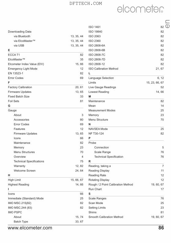
Downloading Data
via Bluetooth 13, 35, 44
via ElcoMaster™ 13, 35, 44
via USB 13, 35, 44
E
ECCA T1 82
ElcoMaster™ 35
Elcometer Index Value (EIV) 15, 66
Emergency Light Mode 12
EN 13523-1 82
Error Codes 69
F
Factory Calibration 20, 61
Firmware Updates 13, 65
Fixed Batch Size 33
Foil Sets 81
G
Gauge
About 3
Accessories 80
Error Codes 69
Features 12
Firmware Updates 13, 65
Icons 66
Maintenance 82
Memory 23
Menu Structures 70
Overview 4
Technical Specifications 75
Warranty 12, 82
Welcome Screen 24, 64
H
High Limit 15, 66, 67
Highest Reading 14, 66
I
Icons 66
Immediate (Standard) Mode 25
IMO MSC.215(82) 82
IMO MSC.244 (83) 82
IMO PSPC
About 15, 74
Batch Type 33, 67
ISO 1461 82
ISO 19840 82
ISO 2063 82
ISO 2360 82
ISO 2808-6A 82
ISO 2808-6B 82
ISO 2808-7C 82
ISO 2808-7D 82
ISO 2808-12 82
ISO Calibration Method 21, 67
L
Language Selection 6, 12
Limits 15, 23, 66, 67
Live Gauge Readings 52
Lowest Reading 14, 66
M
Maintenance 82
Mean 14
Measurement Modes 25
Memory 23
Menu Structure 70
N
NAVSEA Mode 25
NF T30-124 82
P
Probe
Connection 5
Scale Range 76
Technical Specification 76
R
Reading, taking a 7
Reading Display 11
Reading Rate 12
Rotating Display 12
Rough / 2 Point Calibration Method 19, 60, 67
Run Chart 17
S
Scale Ranges 76
Scan Mode 25
Setting Limits 23
Shims 81
Smooth Calibration Method 19, 60, 67
www.elcometer.com 86
en
R
DFTTECH.COM

Software, ElcoMaster™ 35
SSPC PA2 82
Standard (Immediate) Mode 25
SSPC PA2 Calibration Method 21, 67
Standards, Coated Thickness 81
Standards 81
Statistics 14
Swedish Calibration Method 21, 63
Switching On / Off 6
T
Technical Specifications 75
Test Certificates 82
Time and Date 17
Two Point Calibration Method 19, 60, 67
Two Year Gauge Warranty 12, 82
U
Units, Selecting 6
US Navy NSI 009-32 82
US Navy PPI 63101-000 82
W
Welcome Screen 24, 64
Weight 75
Wrist Harness, Fitting 6
Z
Zero Calibration Method 19, 60, 67
Zero Offset Calibration Method 19, 60, 67
Zero Test Plates 81
en
R
www.elcometer.com87
DFTTECH.COM

R
www.elcometer.com
THE NETHERLANDSElcometer NLNewtonlaan 1153584 BH UtrechtTel: +31 (0)30 210.7005Fax: +31 (0)30 210.6666email: [email protected]
GERMANYElcometer Instruments GmbHUlmer Strasse 68D-73431 AalenTel: +49(0)7361 52806 0Fax: +49(0)7361 52806 77e-mail: [email protected]
FRANCE
Elcometer Sarl 4 rue de Micy 45380 La-Chapelle-Saint-Mesmin Tel: +33 (0)2 38 86 33 44Fax: +33 (0)2 38 91 37 66e-mail: [email protected]
ASIA & THE FAR EASTElcometer (Asia) Pte Ltd896 Dunearn RdSime Darby Centre #03-09Singapore 589472,Tel: +65 6462 2822Fax: +65 6462 2860e-mail: [email protected]
ENGLANDElcometer LimitedEdge LaneManchester M43 6BUTel: +44 (0)161 371 6000Fax: +44 (0)161 371 6010e-mail: [email protected]
USAElcometer Inc1893 Rochester Industrial DriveRochester Hills Michigan 48309Tel: +1 248 650 0500Toll Free: 800 521 0635Fax: +1 248 650 0501e-mail: [email protected]
BELGIUMElcometer SARue Vallée 13B-4681 Hermalle /s ArgenteauTel: +32 (0)4 379 96 10Fax: +32 (0)4 374 06 03e-mail: [email protected]
JAPANElcometer KKNisso Dai 23 Building, Room 804, 3-8-25, Toranomon Minato-ku, Tokyo 105-0001 Tel: +81 (3)-6869-0770 Fax: +81 (3)-6809-1442 email: [email protected]
DFTTECH.COM