elct 912: advanced embedded systems - …eee.guc.edu.eg/courses/electronics/advanced embedded...
TRANSCRIPT

ELCT 912:
Advanced Embedded
Systems
Lecture 10: Applications for Programming PIC18 in C
Dr. Mohamed Abd El Ghany,
Department of Electronics and Electrical Engineering

Programming the PIC18 to transfer
data serially
2 Dr. Mohamed Abd el Ghany
Department of Electronics and Electrical Engineering ELCT 912:
Advanced embedded Systems
Winter 2011
1. The TXSTA register is loaded with the value 20H,
indicating asynchronous mode with 8-bit data frame, low
baud rate, and transmit enabled.
2. Make TX pin of PORTC (RC6) an output for data to come
out of the PIC
3. The SPBRG is loaded with value to set the baud rate for
serial data transfer
4. SPEN bit in the RCSTA register is set HIGH to enable the
serial port of PIC18
5. The character byte to be transmitted serially is written into
the TXREG register.
6. Monitor the TXIF bit of the PIR1 register to make sure
UART is ready for next byte
7. To transfer the next character, go to step 5

Programming the PIC18 to transfer data serially
3 Dr. Mohamed Abd el Ghany
Department of Electronics and Electrical Engineering ELCT 912:
Advanced embedded Systems
Winter 2011
Write a C program for the PIC18 to transfer the letter „G‟ serially at
9600 baud, continuously. Use 8-bit data and 1 stop bit. Assume XTAL =
10 MHz.

Programming the PIC18 to transfer data serially
4 Dr. Mohamed Abd el Ghany
Department of Electronics and Electrical Engineering ELCT 912:
Advanced embedded Systems
Winter 2011
Write a PIC18 C program to transfer the message “YES” serially at
9600 baud, 8-bit data, and 1 stop bit. Do this continuously.

Programming the PIC18 to receive
data serially
5 Dr. Mohamed Abd el Ghany
Department of Electronics and Electrical Engineering ELCT 912:
Advanced embedded Systems
Winter 2011
1. The RCSTA register is loaded with the value 90H, to
enable the continuous receive in addition to the 8-bit data
size option
2. The TXSTA register is loaded with the value 00H to
choose the low baud rate option.
3. SPBRG is loaded with a value to set the baud rate
4. Make the RX pin of PORTC (RC7) an input for data to
come into the PIC18.
5. The RCIF flag bit of the PIR1 register is monitored for a
HIGH to see if an entire character has been received yet.
6. When RCIF is raised, the RCREG register has the byte.
Its contents are moved into a safe place
7. To receive the next character, go to Step5

Programming the PIC18 to receive data serially
6 Dr. Mohamed Abd el Ghany
Department of Electronics and Electrical Engineering ELCT 912:
Advanced embedded Systems
Winter 2011
Program the PIC18 in C to receive bytes of data serially and put them
on PORTB. Set the baud rate at 9600, 8-bit data, and 1 stop bit.

Example
7 Dr. Mohamed Abd el Ghany
Department of Electronics and Electrical Engineering ELCT 912:
Advanced embedded Systems
Winter 2011
Write an C18 program to send two different strings to the serial port.
Assuming that SW is connected to pin PORTB.5, monitor its status and
make a decision as follows:
SW = 0; send your first name
SW = 1; send your last name
Assuming XTAL =10 MHz, baud rate of 9600, and 8-bit data
Part 1

Example
8 Dr. Mohamed Abd el Ghany
Department of Electronics and Electrical Engineering ELCT 912:
Advanced embedded Systems
Winter 2011
Part 2

Baud rates for BRGH =1
9 Dr. Mohamed Abd el Ghany
Department of Electronics and Electrical Engineering ELCT 912:
Advanced embedded Systems
Winter 2011
Note : for Fosc = 10 MHz, we have SPBRG = (625000/ Baud Rate) – 1

SPBRG Values for Various Baud
Rates (XTAL = 10 MHz)
10 Dr. Mohamed Abd el Ghany
Department of Electronics and Electrical Engineering ELCT 912:
Advanced embedded Systems
Winter 2011
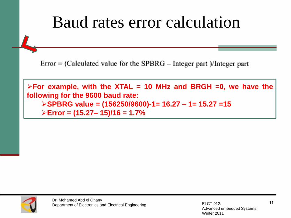
Baud rates error calculation
11 Dr. Mohamed Abd el Ghany
Department of Electronics and Electrical Engineering ELCT 912:
Advanced embedded Systems
Winter 2011
For example, with the XTAL = 10 MHz and BRGH =0, we have the
following for the 9600 baud rate:
SPBRG value = (156250/9600)-1= 16.27 – 1= 15.27 =15
Error = (15.27– 15)/16 = 1.7%

Example
12 Dr. Mohamed Abd el Ghany
Department of Electronics and Electrical Engineering ELCT 912:
Advanced embedded Systems
Winter 2011
Write a PIC18 C program to send the two messages “Normal speed”
and “High Speed” to the serial port. Assuming that SW is connected to
pin PORTB.0, monitor its status and set the baud rate as follows:
SW =0 9600 baud rate
SW =1 38400 baud rate
Assuming XTAL =10 MHz for both cases.
Part 1

Example
13 Dr. Mohamed Abd el Ghany
Department of Electronics and Electrical Engineering ELCT 912:
Advanced embedded Systems
Winter 2011
Part 2

Programming Timer Interrupts
14 Dr. Mohamed Abd el Ghany
Department of Electronics and Electrical Engineering ELCT 912:
Advanced embedded Systems
Winter 2011
Timer Interrupt Flag Bits and Associated Registers
INTCON Register with Timer0 Interrupt Enable and Interrupt Flag

Programming Timer Interrupts
15 Dr. Mohamed Abd el Ghany
Department of Electronics and Electrical Engineering ELCT 912:
Advanced embedded Systems
Winter 2011
The Role of Timer Interrupt Enable Flag (TMRxIE)

The Difference Between the
RETURN and RETFIE Instructions
16 Dr. Mohamed Abd el Ghany
Department of Electronics and Electrical Engineering ELCT 912:
Advanced embedded Systems
Winter 2011
Explain why we cannot use RETURN instead of RETFIE as the
last instruction of ISR
Both perform the same actions of popping off the top bytes of
the stack into the program counter and making the PIC18 return
to where it left off. However, RETFIE also performs the additional
task of clearing the GIE flag, indicating that the servicing of the
interrupt is over and the PIC18 now can accept a new interrupt. If
you use RETURN instead of RETFIE as the last instruction of
interrupt service routine, you simply block any new interrupt
after the first interrupt, because the GIE would indicate that the
interrupt is still being serviced.

Example
17 Dr. Mohamed Abd el Ghany
Department of Electronics and Electrical Engineering ELCT 912:
Advanced embedded Systems
Winter 2011
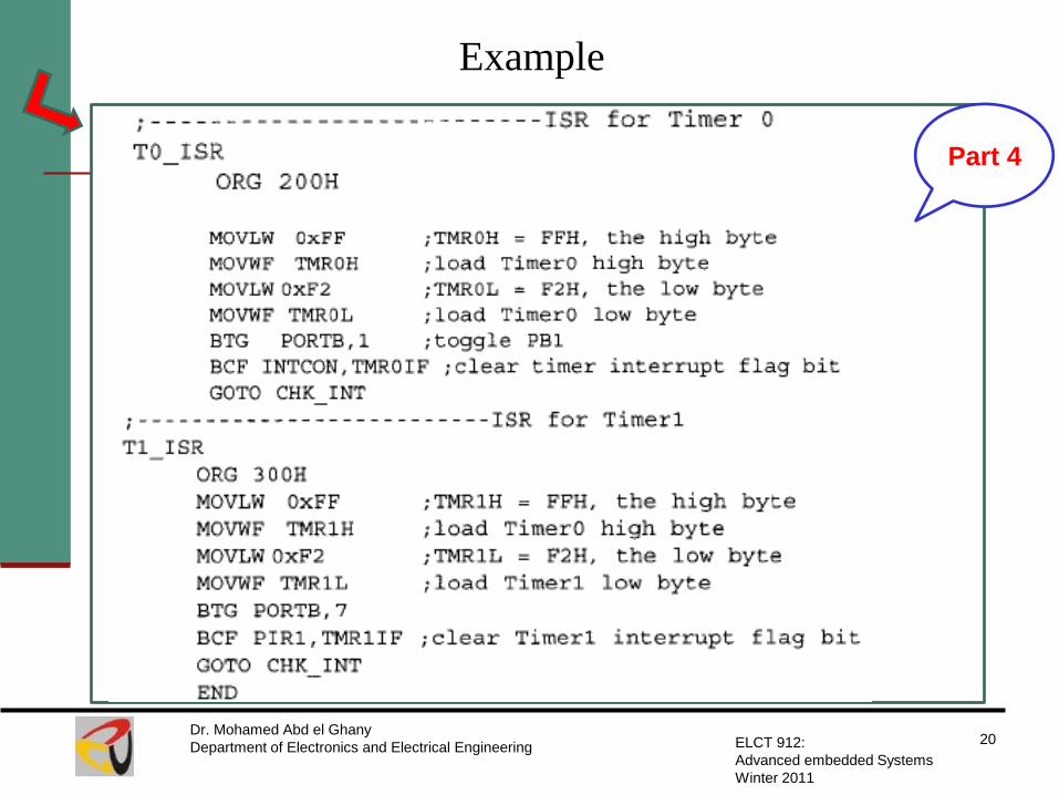
Write a program to use Timer0 and Timer1 interrupts to generate
square waves on pins RB1 and RB7 respectively, while data is being
transferred from PORTC to PORTD
Part 1

Example
18 Dr. Mohamed Abd el Ghany
Department of Electronics and Electrical Engineering ELCT 912:
Advanced embedded Systems
Winter 2011
Part 2

Example
19 Dr. Mohamed Abd el Ghany
Department of Electronics and Electrical Engineering ELCT 912:
Advanced embedded Systems
Winter 2011
Part 3
Example
20 Dr. Mohamed Abd el Ghany
Department of Electronics and Electrical Engineering ELCT 912:
Advanced embedded Systems
Winter 2011
Part 4

PIC18 interrupt Programming in C
21 Dr. Mohamed Abd el Ghany
Department of Electronics and Electrical Engineering ELCT 912:
Advanced embedded Systems
Winter 2011
Notes:
The C18 compiler uses ”#pragma code” to place code
at a specific ROM address.
Because the C18 does not pace an ISR at the interrupt
vector table automatically, we must use assembly
language instruction GOTO at the interrupt vector to
transfer control to the ISR.
PIC18 interrupt Programming in C
22 Dr. Mohamed Abd el Ghany
Department of Electronics and Electrical Engineering ELCT 912:
Advanced embedded Systems
Winter 2011
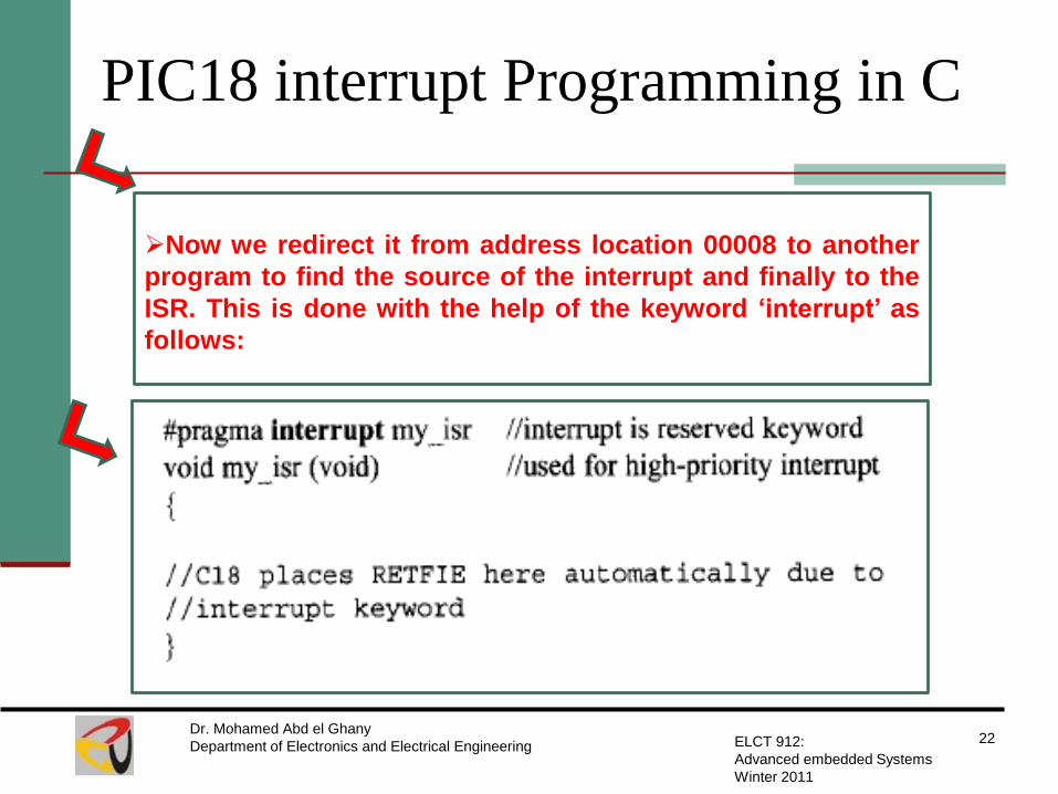
Now we redirect it from address location 00008 to another
program to find the source of the interrupt and finally to the
ISR. This is done with the help of the keyword „interrupt‟ as
follows:

Example
23 Dr. Mohamed Abd el Ghany
Department of Electronics and Electrical Engineering ELCT 912:
Advanced embedded Systems
Winter 2011
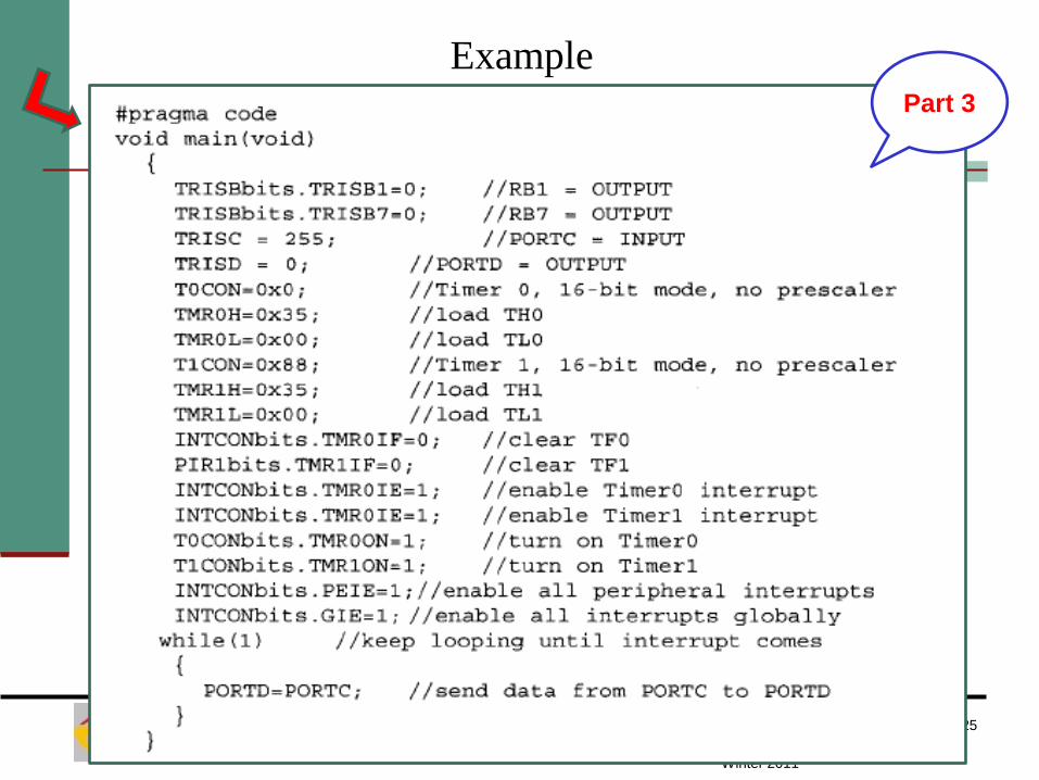
Write a program to use Timer0 and Timer1 interrupts to generate
square waves on pins RB1 and RB7 respectively, while data is being
transferred from PORTC to PORTD ( C version)
Part 1

Example
24 Dr. Mohamed Abd el Ghany
Department of Electronics and Electrical Engineering ELCT 912:
Advanced embedded Systems
Winter 2011
Part 2
Example
25 Dr. Mohamed Abd el Ghany
Department of Electronics and Electrical Engineering ELCT 912:
Advanced embedded Systems
Winter 2011
Part 3

Example
26 Dr. Mohamed Abd el Ghany
Department of Electronics and Electrical Engineering ELCT 912:
Advanced embedded Systems
Winter 2011
Part 4