electra-saver electra-saver ii stationary … compressor om.pdf · airsmart™ controller eah99d -...
TRANSCRIPT

13-21-601
Version: 02March 15, 2011
ELECTRA-SAVER ELECTRA-SAVER II
STATIONARY BASE-MOUNTED COMPRESSOR
With
AirSmart™ Controller
EAH99D - 50 HP EBH99H - 40, 50 HP
EAM99D, EBM99M - 60, 75 HP EAP99K, EBP99K - 100 HP
INTERNATIONAL MODELS
EBM99N 60, 75, 100 HP (45, 56, 75 KW)
OPERATING AND
SERVICE MANUAL
13-21-601 Page 1
MAINTAIN COMPRESSOR RELIABILITY AND PERFORMANCE WITH GENUINE GARDNER DENVER® COMPRESSOR PARTS AND SUPPORT SERVICES
Gardner Denver® Compressor genuine parts, manufactured to design tolerances, are developed for optimum dependability – specifically for Gardner Denver compressor systems. Design and material innovations are the result of years of experience with hundreds of different compressor applications. Reliability in materials and quality assurance is incorporated in our genuine replacement parts. Your authorized Gardner Denver Compressor distributor offers all the backup you’ll need. An AirSmart™ network of authorized distributors provides the finest product support in the air compressor industry. Your authorized distributor can support your Gardner Denver air compressor with these services:
1. Trained parts specialists to assist you in selecting the correct replacement parts.
2. Factory warranted new and remanufactured rotary screw airends. Most popular model remanufactured airends are maintained in stock at the Remanufacturing Center in Indianapolis, IN., for purchase on an exchange basis with liberal core credit available for the replacement unit.
3. A full line of factory tested AEON™ compressor lubricants specifically formulated for use in Gardner Denver compressors.
4. Repair and maintenance kits designed with the necessary parts to simplify servicing your compressor. Authorized distributor service technicians are factory trained and skilled in compressor maintenance and repair. They are ready to respond and assist you by providing fast, expert maintenance and repair services. For the location of your local authorized Gardner Denver Air Compressor distributor, refer to the yellow pages of your phone directory, check the Gardner Denver Web Site at www.gardnerdenver.com or contact:
Gardner Denver 1800 Gardner Expressway Quincy, IL 62305 Phone: (217) 222-5400 Fax: (217) 224-7814
INSTRUCTIONS FOR ORDERING REPAIR PARTS/REMANUFACTURED AIRENDS
Whenever an airend requires replacement or repair, Gardner Denver offers an industry unique, factory remanufactured airend exchange program. From its modern Remanufacturing center in Indianapolis, IN., Gardner Denver is committed to supplying you with the highest quality, factory remanufactured airends that are guaranteed to save you time, aggravation and money
When ordering parts, specify Compressor MODEL, Method of Cooling, POWER and SERIAL NUMBER (see nameplate on unit). The Airend Serial Numbers are also stamped on top of the discharge bearing carrier castings.
All orders for Parts should be placed with the nearest authorized distributor. Where NOT specified, quantity of parts required per compressor or unit is one (1); where more than one is required per unit, quantity is indicated in parenthesis. SPECIFY EXACTLY THE NUMBER OF PARTS REQUIRED. DO NOT ORDER BY SETS OR GROUPS. To determine the Right-Hand and Left-Hand side of a compressor, stand at the motor end and look toward the compressor. Right-Hand and Left- Hand are indicated in parenthesis following the part name, i.e. (RH) and (LH), when appropriate.

13-21-601 Page 2
WARNING – PROHIBITION – MANDATORY LABEL INFORMATION
Gardner Denver Rotary Screw compressors are the result of advanced engineering and skilled manufacturing. To be assured of receiving maximum service from this machine, the owner must exercise care in its operation and maintenance. This book is written to give the operator and maintenance department essential information for day-to-day operation, maintenance and adjustment. Careful adherence to these instructions will result in economical operation and minimum downtime.
Boxed text formats are used, within this manual, to alert users of the following conditions: Safety Labels are used, within this manual and affixed to the appropriate areas of the compressor package, to alert users of the following conditions:
Indicates a hazard with a high level of risk, which if not avoided, WILL result in death or serious injury.
Equipment starts automatically
Cutting of Finger or Hand Hazard – Rotating impeller blade
Cutting of Finger or Hand Hazard – Rotating fan blade
Health Hazard – Explosive Release of Pressure
High Voltage – Hazard of Shock, Burn, or Death Present until Electrical Power is Removed
Entanglement of Fingers or Hand/Rotating Shaft

13-21-601 Page 3
Indicates a hazard with a medium level of risk which, if not avoided, COULD result in death or serious injury.
Asphyxiation Hazard – Poisonous Fumes or Toxic Gases in Compressed Air
Indicates a hazard with a low level of risk which, if not avoided, MAY result in a minor or moderate injury.
Burn Hazard – Hot surface
PROHIBITION/MANDATORY ACTION REQUIREMENTS
Do not Operate Compressor with Guard
Removed
Do Not Lift Equipment with Hook – No Lift Point
Handle Package at Forklift Points Only
Lockout Electrical Equipment in De-Energized
State
Loud Noise Hazard – Wear Ear Protection
Read the Operator’s Manual Before Proceeding
with Task

13-21-601 Page 4
SAFETY PRECAUTIONS
Safety is everybody’s business and is based on your use of good common sense. All situations or circumstances cannot always be predicted and covered by established rules. Therefore, use your past experience, watch out for safety hazards and be cautious. Some general safety precautions are given below:
Failure to observe these notices could result in injury to or death of personnel.
• Keep fingers and clothing away from rotating fan, drive coupling, etc.
• Disconnect the compressor unit from its power source, lockout and tagout before working on the unit – this machine is automatically controlled and may start at any time.
• Do not loosen or remove the oil filler plug, drain plugs, covers, the thermostatic mixing valve or
break any connections, etc., in the compressor air or oil system until the unit is shut down and the air pressure has been relieved.
• Electrical shock can and may be fatal.
• Perform all wiring in accordance with the National Electrical Code (NFPA-70) and any applicable
local electrical codes. Wiring and electrical service must be performed only by qualified electricians.
• Open main disconnect switch, lockout and tagout before working on the control, wait 10 minutes
and check for voltage.
Failure to observe these notices could result in damage to equipment.
• Stop the unit if any repairs or adjustments on or around the compressor are required.
• Do not use the air discharge from this unit for breathing – not suitable for human consumption.
• An Excess Flow Valve should be on all compressed air supply hoses exceeding 1/2 inch inside diameter (OSHA Regulation, Section 1926.302).
• Do not exceed the rated maximum pressure values shown on the nameplate.
• Do not operate unit if safety devices are not operating properly. Check periodically. Never
bypass safety devices.

13-21-601 Page 5
TABLE OF CONTENTS
Maintain Compressor Reliability And Performance With Genuine Gardner Denver Compressor Parts And Support Services ..........................................................................1 Instructions For Ordering Repair Parts/Remanufactured Airends ................................................................1 Warning – Prohibition – Mandatory Label Information..................................................................................2 Safety Precautions ........................................................................................................................................4 Index..............................................................................................................................................................6 List Of Illustrations.........................................................................................................................................8 Section 1, General Information .....................................................................................................................9 Section 2, Installation ..................................................................................................................................13 Section 3, Starting & Operating Procedures ...............................................................................................23 Section 4, Controls & Instrumentation ........................................................................................................28 Section 5, Lubrication, Oil Cooler, Oil Filter & Separator............................................................................73 Section 6, Air Filter......................................................................................................................................92 Section 7, Coupling .....................................................................................................................................94 Section 8, Maintenance Schedule ..............................................................................................................97 Section 9, Troubleshooting .........................................................................................................................99
This book covers the following models:
HP PSIG Model Parts List Controller Manual
50 100, 125 EAH99D 13-22-500 13-17-600
40, 50 100, 125, 150, 175, 200 EBH99H 13-21-502 13-17-600
75 100, 125 EAM99D 213-9-500 13-17-600
60, 75 100, 125, 150, 175, 200 EBM99M 213-9-501 13-17-600
100 100, 125, 150 EAP99K 213-9-500 13-17-600
100 100, 125, 150, 175, 200 EBP99K 213-9-501 13-17-600

13-21-601 Page 6
INDEX
Addition Of Oil Between Changes ...................80 Aftercooler Piping.............................................78 Air Filter Element Life.......................................93 Air Filter Vacuum Switch ..................................34 Air Filter, Heavy Duty (Standard) .....................92 Air Filter, Section 6...........................................92 Air Flow In The Compressor System .................9 Air-Cooled Units, Location ...............................14 Airsmart™ Operation .......................................28 Auxiliary Air Receiver .......................................17 Blowdown Valve...............................................31 Blowdown Valve Piping....................................18 Check
Daily..............................................................25 Cold Ambient Operation...................................80 Cold Weather Operation ..................................16 Cold Weather Operation, Installation For.........16 Compression Principle .......................................9 Compressor........................................................9 Compressor Capacity Control - Turn Valve Units
Only ..............................................................36 Compressor Oil Cooler - Water-Cooled Heat
Exchanger ....................................................85 Control Devices................................................28 Control Piping...................................................17 Controller..........................................................28 Controls & Instrumentation, Section 4 .............28 Cooling, Sealing And Lubrication.....................10 Coupling ...........................................................94 Daily Check ......................................................25 Discharge Service Line ....................................18 Discharge Thermistor.......................................35 Drain
Oil Reservoir.................................................15 Draining And Cleaning Oil System...................82 Electrical Wiring ...............................................21 Emergency Stop Push-Button..........................35 Enclosure .........................................................15 Fan Starter .......................................................35 Filling Oil Reservoir ..........................................83 Filter Element ...................................................92 Foundation .......................................................15 Fuse Blocks......................................................35 General Information, Section 1 ..........................9 Grounding.........................................................21 Heat Exchanger (Oil) Piping.............................79 High Temperature Operation ...........................74 Inlet Line...........................................................17 Inlet Screen And Tube .....................................93
Inlet Valve ........................................................32 Installation For Cold Weather Operation .........16 Installation, Section 2.......................................13 Lifting Unit ........................................................13 Location ...........................................................13
Air-Cooled Units ...........................................14 Water-Cooled Units......................................15
Lubricant Recommended.............................................73
Lubricant Change Procedure...........................80 Lubrication
Motor ............................................................22 Lubrication, Cooling And Sealing.....................10 Lubrication, Oil Cooler, Oil Filter & Separator .73 Main Starter .....................................................35 Maintenance Schedule, Section 8 ...................97 Minimum Discharge Pressure Valve................31 Moisture In The Oil System .............................74 Moisture Separator/Trap..................................17 Motor Lubrication .............................................22 Oil Change Interval ..........................................81 Oil Cooler - Radiator Type ...............................85 Oil Filter............................................................84 Oil Level Gauge .........................................31, 81 Oil Reservoir ....................................................88 Oil Reservoir Drain...........................................15 Oil Separator
Compressor (Gd Eliminator) ........................88 Inspection .....................................................89 Oil Carryover ................................................88 Pressure Differential Gauging ......................89 Removal For Inspection Or Replacement....90
Oil Specifications .............................................73 Oil System
Compressor..................................................73 Draining And Cleaning .................................82
Oil System Check ............................................90 Air And Oil Discharge Temperature .............90 Oil Cooler Oil Pressure Differential (Air-
Cooled Radiator) ......................................91 Oil Cooler Oil Pressure Differential (Water-
Cooled Heat Exchanger) ..........................91 Oil Cooler Temperature Differential (Air-
Cooled Radiator) ......................................91 Oil Cooler Temperature Differential (Water-
Cooled Heat Exchanger) ..........................91 Oil Cooler Water Pressure Differential (Water-
Cooled Heat Exchanger) ..........................91 Oil Inlet Pressure..........................................90 Oil Inlet Temperature ...................................90
Operation High Temperature ........................................74

13-21-601 Page 7
Parallel Piping ..................................................21 Piping
Series............................................................20 Power Supply ...................................................35 Pressure Differential Gauging..........................89 Pressure Regulator ..........................................33 Prestart-Up Instructions ...................................23 Purge Valve......................................................33 Quick Start Guide.............................................26 Relief Valve ......................................................29 Remote Mounted Elevated Cooler Assembly ..78 Reservoir Pressure Transducer .......................34 Reservoir Thermistor........................................35 Safety Precautions .............................................4 Sealing, Lubrication And Cleaning...................10 Series Piping ....................................................20 Service Check List ...........................................97
Every 1000 Hours Operation........................97 Every 125 Hours Operation..........................97 Every 8 Hours Operation..............................97 Every 8000 Hours Operation........................97 Every Year....................................................97 Motor Lubrication..........................................97 Oil Separator ................................................97
Service Check List Air Filter ........................................................97
Shuttle Valve....................................................33 Solenoid Valves Ivc And Ivo ............................33 Solenoid Valves Tvc And Tvo..........................34 Starting & Operating Procedures, Section 3....23 Starting The Unit ..............................................25
Unit Cold.......................................................25 Unit Hot ........................................................25
Stopping The Unit ............................................25 System Pressure Transducer ..........................34 Terminal Strip...................................................35 Thermal Control (Thermostatic Mixing) Valve .85 Troubleshooting, Section 9 ..............................99 Turn Valve..................................................10, 34 Turn Valve Actuator .........................................34 Warning – Prohibition – Mandatory Label
Information .....................................................2 Water Flow Control Valve For Heat Exchanger
.....................................................................87 Water Piping ....................................................19 Water Shutoff Valve - Water-Cooled Heat
Exchanger ....................................................88 Water-Cooled Units, Location..........................15

13-21-601 Page 8
LIST OF ILLUSTRATIONS
Figure 1-1 – Compression Cycle....................................................................................................................................9 Figure 1-2 – Starter Box...............................................................................................................................................10 Figure 1-3 – Control Box ..............................................................................................................................................10 Figure 1-4 – Compressor / Motor Side .........................................................................................................................11 Figure 1-5 – Cooler / Reservoir Side............................................................................................................................11 Figure 1-6 – Air/Oil Flow Diagram................................................................................................................................12
Figure 2-1 – Typical Compressor Room ......................................................................................................................14 Figure 2-2 – Air Flow Chart ..........................................................................................................................................14 Figure 2-3 – Cold Weather Installation.........................................................................................................................16 Figure 2-4 – Inlet Line Lengths ....................................................................................................................................17 Figure 2 5 – Heat Exchanger (Oil Cooler) Approximate Water Flow............................................................................18 Figure 2-6 – Aftercooler Approximate Water Flow .......................................................................................................19 Figure 2-7 – Series Piping............................................................................................................................................20 Figure 2-8 – Parallel Piping..........................................................................................................................................20
Figure 4-1 – Key Pad ...................................................................................................................................................29 Figure 4-2 – Schematic Tubing Diagram......................................................................................................................30 Figure 4-3 – Blowdown Valve ......................................................................................................................................31 Figure 4-4 – Minimum Discharge Pressure/Check Valve.............................................................................................31 Figure 4-5 – Inlet Valve ................................................................................................................................................32 Figure 4-6 – Shuttle Valve............................................................................................................................................33 Figure 4-7 – Turn Valve – Electra-Saver Only .............................................................................................................34 Figure 4-8 – Control Schematic – Compressor Unloaded – Constant Speed Mode ....................................................37 Figure 4-9 – Control Schematic – Compressor At Full Load – Constant Speed Mode.................................................38 Figure 4-10 – Control Schematic – Compressor Unloaded – Low Demand Mode Or Auto Mode................................39 Figure 4-11 – Control Schematic – Compressor At Full Load ......................................................................................40 Figure 4-12 – Control Schematic – Compressor Fully Unloaded – Low Demand Mode Switch Off .............................41 Figure 4-13 – Control Schematic – Compressor Fully Loaded – Low Demand Mode Switch On ................................42 Figure 4-14 – Wiring Diagram – Wye Delta (Air–Cooled / Water–Cooled) - 200, 230, 460 Volt..................................43 Figure 4-15 – Wiring Diagram – Wye Delta (Air–Cooled / Water–Cooled) - 575 Volt..................................................45 Figure 4-16 – Wiring Diagram – Full Volt (Air–Cooled / Water–Cooled) – 200 & 230 Volt ..........................................47 Figure 4-17 – Wiring Diagram – Full Volt (Air–Cooled / Water–Cooled) – 460 Volt ....................................................49 Figure 4-18 – Wiring Diagram – Full Volt (Air–Cooled / Water–Cooled) – 575 Volt ....................................................51 Figure 4-19 – Wiring Diagram – Less Starter (Air–Cooled / Water–Cooled) – 200, 230, 460 Volt .............................53 Figure 4-20 – Wiring Diagram – Less Starter (Air–Cooled / Water–Cooled) – 575 Volt ..............................................55 Figure 4-21 – Wiring Diagram – Wye Delta (Air–Cooled / Water–Cooled) – 200/230 Volt..........................................57 Figure 4-22 – Wiring Diagram – Wye Delta (Air–Cooled / Water–Cooled) – 380/460 Volt..........................................59 Figure 4-23 – Wiring Diagram – Wye Delta (Air–Cooled / Water–Cooled) – 575 Volt.................................................61 Figure 4-24 – Wiring Diagram – Full Volt (Air–Cooled / Water–Cooled) – 200 & 230 Volt ..........................................63 Figure 4-25 – Wiring Diagram – Full Volt (Air–Cooled / Water–Cooled) – 380/460 Volt .............................................65 Figure 4-26 – Wiring Diagram – Full Volt (Air–Cooled / Water–Cooled) – 575 Volt ....................................................67 Figure 4-27 – Wiring Diagram – Less Starter (Air–Cooled / Water–Cooled) – 200, 230, 380, 460 Volt .....................69 Figure 4-28 – Wiring Diagram – Less Starter (Air–Cooled / Water–Cooled) – 575 Volt .............................................71
Figure 5-1 – Dew Point Chart °F ..................................................................................................................................75 Figure 5-2 – Dew Point Chart °C..................................................................................................................................75 Figure 5-3 – Flow Diagram – Air/Oil System ................................................................................................................76 Figure 5-4 – Oil Flow Diagram – Remote Overhead Mounted Cooler..........................................................................77 Figure 5-5 – Cooler Drain Detail...................................................................................................................................78 Figure 5-6 – Oil Level Gauge .......................................................................................................................................81 Figure 5-7 – Oil Change Interval ..................................................................................................................................82 Figure 5-8 – Approximate Oil System Capacities.........................................................................................................83 Figure 5-9 – Thermostatic Mixing Valve Element.........................................................................................................85 Figure 5-10 – Water Control Valve...............................................................................................................................86 Figure 5-11 – Dew Point Temperature VS. Ambient Temperature...............................................................................87 Figure 5-12 – Oil Separator..........................................................................................................................................88
Figure 6-1 – Heavy Duty Air Filter ................................................................................................................................92
Figure 7-1 – Installation Of Coupling Cushions............................................................................................................94

13-21-601 Page 9
SECTION 1 GENERAL INFORMATION
Figure 1-1 – COMPRESSION CYCLE
COMPRESSOR - The Gardner Denver Rotary Screw compressor is a single stage, positive displacement rotary machine using meshing helical rotors to effect compression. Both rotors are supported between high capacity roller bearings located outside the compression chamber. Single width cylindrical roller bearings are used at the inlet end of the rotors to carry part of the radial loads. Tapered roller bearings at the discharge end locate each rotor axially and carry all thrust loads and the remainder of the radial loads.
COMPRESSION PRINCIPLE (Figure 1-1) - Compression is accomplished by the main and secondary rotors synchronously meshing in a one-piece cylinder. The main rotor has four (4) helical lobes 90° apart. The secondary rotor has six (6) matching helical grooves 60° apart to allow meshing with main rotor lobes. The air inlet port is located on top of the compressor cylinder near the drive shaft end. The discharge port is near the bottom at the opposite end of the compressor cylinder. Figure 1-1 is an inverted view to show inlet and discharge ports. The compression cycle begins as rotors unmesh at the inlet port and air is drawn into the cavity between the main rotor lobes and secondary rotor grooves (A). When the rotors pass the inlet port cutoff, air is trapped in the interlobe cavity and flows axially with the meshing rotors (B). As meshing continues, more of the main rotor lobe enters the secondary rotor groove, normal volume is reduced and pressure increases. Oil is injected into the cylinder to remove the heat of compression and seal internal clearances. Volume reduction and pressure increase continues until the air/oil mixture trapped in the interlobe cavity by the rotors passes the discharge port and is released to the oil reservoir (C). Each rotor cavity follows the same “fill-compress-discharge” cycle in rapid succession to produce a discharge air flow that is continuous, smooth and shock free. AIR FLOW IN THE COMPRESSOR SYSTEM (Figure 5-3, page 76) - Air enters the air filter and passes through the inlet unloader valve to the compressor. After compression, the air/oil mixture passes into the oil reservoir where most of the entrained oil is removed by velocity change and impingement and drops back into the reservoir. The air and remaining oil passes into the separator and separator housing where the oil is separated and passes through tubing connecting the separator housing and compressor. The air passes through the minimum pressure valve, discharge check valve and cooler, then to the plant air lines.

13-21-601 Page 10
LUBRICATION, COOLING AND SEALING - Oil is forced by air pressure from the oil reservoir through the oil cooler, thermostatic mixing valve, and oil filter and discharges into the compressor main oil gallery. A portion of the oil is directed through internal passages to the bearings, gears and shaft oil seal. The balance of the oil is injected directly into the compression chamber to remove heat of compression, seal internal clearances and lubricate the rotors. TURN VALVE (ELECTRA-SAVER ONLY) - The turn valve is a rotary helical valve located on the discharge side of the cylinder toward the inlet end. The valve opens and closes ports in the cylinder which communicates with the inlet passage. This varies the compressor rotor volume to match the demand for air, thus reducing the part-load power requirement.
Figure 1-2 – STARTER BOX
Figure 1-3 – CONTROL BOX
217ECM797-A (Ref. Drawing)

13-21-601 Page 11
Figure 1-4 – COMPRESSOR / MOTOR SIDE
Figure 1-5 – COOLER / RESERVOIR SIDE
217ECM797-A (Ref. Drawing)

13-21-601 Page 12
Figure 1-6 – AIR/OIL FLOW DIAGRAM
219ECM797-A (Ref. Drawing)

13-21-601 Page 13
SECTION 2 INSTALLATION GENERAL - On receipt of the unit, check for any damage that may have been incurred during transit. Report any damage or missing parts as soon as possible
Do not electric weld on the compressor or base; bearings can be damaged by passage of current.
LIFTING UNIT - Proper lifting and/or transporting methods must be used to prevent damage. Lifting slots are provided in the base for tow motor use. The unit may also be moved into location by rolling on bars.
Lift compressor package by base only. Do not use other places such as motors, compressors or discharge manifold piping as lifting points. The eyebolts or lugs provided on the motors are for lifting the motors only and should not be used to lift any additional weight. All eyebolts must be securely tightened. When lifting the motors, the lifting angle must not exceed 15 degrees. Failure to observe this warning may result in damage to equipment or personal injury.
Compressor, air/oil reservoir, separator chamber and all piping and tubing may be at high temperature during and after operation.
LOCATION - The compressor should be installed, whenever possible, in a clean, well-lighted, well-ventilated area with ample space all around for maintenance. Select a location that provides a cool, clean, dry source of air. In some cases it may be necessary to install the air filter at some distance from the compressor to obtain proper air supply.
CCCAAAUUUTTTIIIOOONNN
CCCAAAUUUTTTIIIOOONNN
13-21-601 Page 14
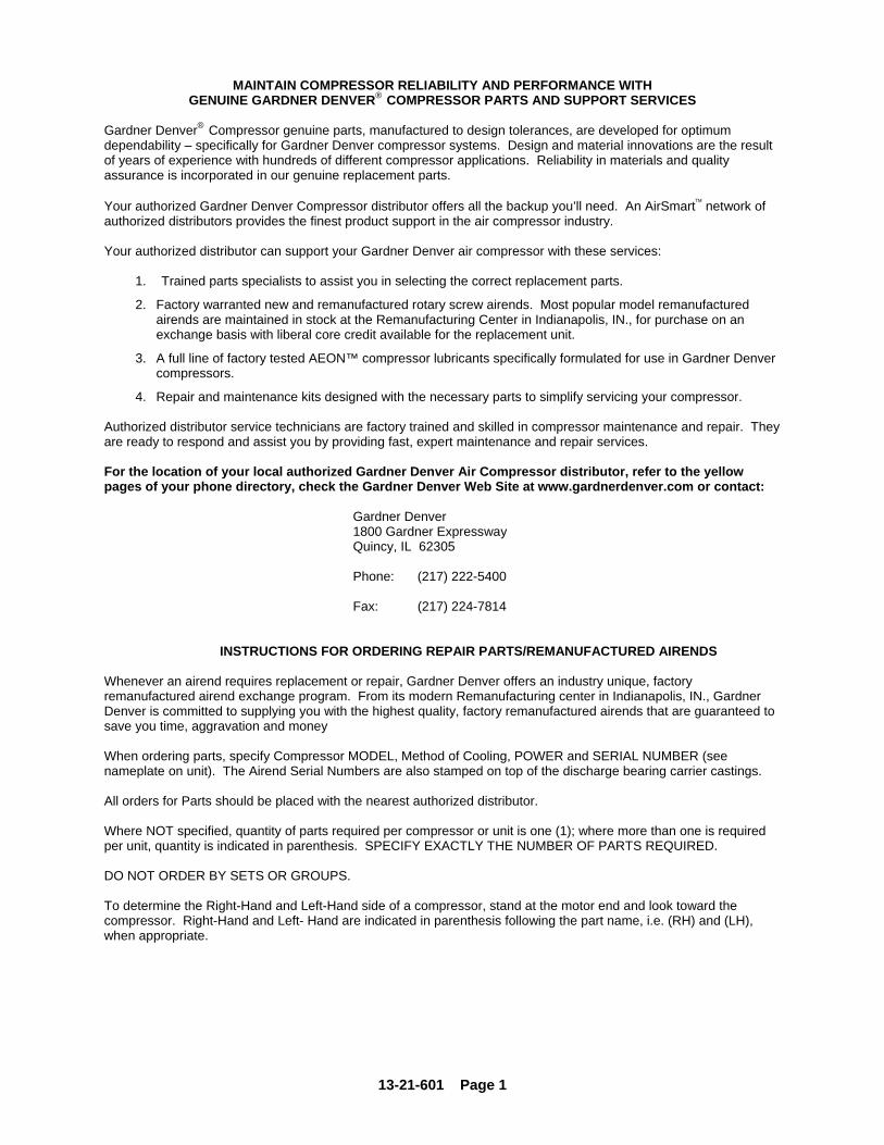
Both the air-cooled and water-cooled units require cooling air as well as air to the compressor inlet. Proper ventilation MUST be provided; hot air must be exhausted from the compressor operating area. A typical inlet-outlet air flow arrangement is shown in Figure 2-1.
Figure 2-1 – TYPICAL COMPRESSOR ROOM
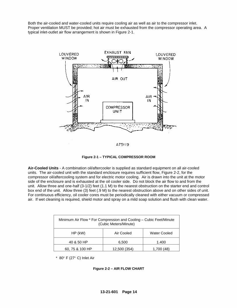
Air-Cooled Units - A combination oil/aftercooler is supplied as standard equipment on all air-cooled units. The air-cooled unit with the standard enclosure requires sufficient flow, Figure 2-2, for the compressor oil/aftercooling system and for electric motor cooling. Air is drawn into the unit at the motor side of the enclosure and is exhausted at the oil cooler side. Do not block the air flow to and from the unit. Allow three and one-half (3-1/2) feet (1.1 M) to the nearest obstruction on the starter end and control box end of the unit. Allow three (3) feet (.9 M) to the nearest obstruction above and on other sides of unit. For continuous efficiency, oil cooler cores must be periodically cleaned with either vacuum or compressed air. If wet cleaning is required, shield motor and spray on a mild soap solution and flush with clean water.
Minimum Air Flow * For Compression and Cooling – Cubic Feet/Minute (Cubic Meters/Minute)
HP (kW) Air Cooled Water Cooled
40 & 50 HP 6,500 1.400
60, 75 & 100 HP 12,500 (354) 1,700 (48) * 80° F (27° C) Inlet Air
Figure 2-2 – AIR FLOW CHART

13-21-601 Page 15
NNNOOOTTTIIICCCEEE
For aluminum oil coolers, do not use any cleaning solution that is not compatible with aluminum. Use of improper solution may result in damage to the cooler.
Water-Cooled Units - The water-cooled unit with the standard enclosure requires sufficient air flow, Figure 2-2, for electric motor cooling. Air is drawn into the unit at the top of the enclosure and is exhausted at the motor side. Do not block air flow to and from unit. Allow three and one-half (3-1/2) feet (1.1 m) to the nearest obstruction on the starter end and control box side of the unit. Allow three (3) feet (.9 m) to the nearest obstruction above and on other sides of the unit. FOUNDATION - The Gardner Denver Rotary Screw compressor requires no special foundation, but should be mounted on a smooth, solid surface. Whenever possible install the unit near level. Temporary installation may be made at a maximum 10° angle lengthwise or 10° sidewise. Mounting bolts are not normally required. However, installation conditions such as piping rigidity, angle of tilt, or danger of shifting from outside vibration or moving vehicles may require the use of mounting bolts and shims to provide uniform support for the base. OIL RESERVOIR DRAIN - The oil drain is piped from the bottom of the reservoir to the side of the frame. This drain is approximately 4.50 inches (115 mm) above the floor level. If this is not sufficient to conveniently drain the oil some other methods of providing drain are: 1. Elevate the compressor unit on a suitable structure to obtain the desired drain height. 2. Construct an oil sump or trough below the floor level and pump or bail the drained oil. 3. Pump oil from the reservoir filler opening or drain to a container.
If the compressor unit base is raised above floor level, the space between the floor and the base bottom must be closed with solid material all around to prevent recirculation of hot air from the oil cooler end and over temperature operation.
ENCLOSURE - The compressor, electric motor, oil cooler and aftercooler are mounted inside the enclosure. Service doors are provided for maintenance access. Be sure to allow enough space around the unit for the doors to open completely. Any of the enclosure doors may be removed by opening the door and lifting it up slightly to disengage the hinges. The motor inspection/air filter service panel is held by two latches and lifts away from the enclosure. The air outlet panel is attached by screws to the enclosure and is not readily removable.
Do not operate the compressor with the fan and coupling guard removed. Exposed fan and couplings may cause injury to personnel.
CCCAAAUUUTTTIIIOOONNN

13-21-601 Page 16
Figure 2-3 – COLD WEATHER INSTALLATION
INSTALLATION FOR COLD WEATHER OPERATION (Figure 2-3) - It is recommended that the unit be installed inside a shelter that will be heated to temperatures above freezing (32°F, 0°C). This will eliminate many of the problems associated with operating units in cold climates where freezing rain, drifting snow, freezing condensate and bitter cold temperatures are encountered. Refer to Engineering Data Sheet 13-9-411 for the advantages of using the heat recovered from rotary compressors. This heat recovery could easily pay for an adequate shelter for the unit. When an outside installation must be made, the precautions required will depend on the severity of the environment. The following are general guidelines for outside installations: Cold Weather (Down To +10°F, -12°C) 1. Be sure all drains, traps, and control lines, including pressure transducer lines are heated to avoid
freezing of condensate. Heat tape with thermostat control is generally satisfactory for this purpose and can be obtained at various local plumbing or hardware outlets at nominal cost.
2. If an air-cooled aftercooler is to be used, provisions to bypass the aftercooler must be made. Since
cold air contains very little moisture, successful operation can be achieved without the aftercooler. 3. Provide at least some simple shelter such as a plywood windbreak to protect against drifting snow. 4. Use only Gardner Denver AEON 9000 SP lubricant. 5. Monitor the unit carefully during start-up and operation to be sure it is functioning normally. 6. Specify UL TYPE 4 enclosure for electrical devices.

13-21-601 Page 17
Extreme Cold Weather Operation (Down To -10°F, -23°C) In addition to the above, the following should be provided: 1. It will be necessary to provide shutters or to block off part of the cooler in some manner since the
cooler is greatly oversized for operation in these low temperatures. Since shutters are not provided as a factory option, blocking off a portion of the cooler with plywood should be satisfactory.
2. Auto operation should not be used in extreme environments. 3. Some means of providing heat during shutdown. Start-up should be provided. There are various
methods to accomplish this, but since openings are not provided for sump heaters, the use of radiant heaters is recommended. The heaters should be sized to provide at least a +10° F (-12 C) environment for coolers, motor and sump. Figure 2-3, page16, shows how these might be located in a typical installation and sizes required.
Remember unsheltered (outside) installations should be avoided where possible. Installation next to a heated building where enough heat can be used to keep the compressor room above freezing will save many complications in the operation and installation of the unit. Refer to Engineering Data Sheet 13-9-411, available from an authorized Gardner Denver distributor, for the advantages of using the heat recovered from rotary compressors. This heat recovery could easily pay for an adequate shelter for the unit. AUXILIARY AIR RECEIVER - An auxiliary air receiver is not required if the piping system is large and provides sufficient storage capacity to prevent rapid cycling. When used, an air receiver should be of adequate size, provided with a relief valve of proper setting, a pressure gauge and a means of draining condensate. MOISTURE SEPARATOR/TRAP - Since the unit is equipped with a built-in aftercooler, a combination moisture separator and trap is furnished with the unit. CONTROL PIPING - Control piping is not necessary since the Rotary Screw compressor unit is factory wired and piped for the control system specified. INLET LINE - Where an inlet line is used between the air filter and the compressor, it must be thoroughly cleaned on the inside to prevent dirt or scale from entering the compressor. If welded construction is used, the line must be shot blasted and cleaned to remove welding scale. In either case, the inlet line must be coated internally by galvanizing or painting with a moisture and oil-proof sealing lacquer. Up to ten (10) feet (3 meters) in length, the inlet line should be the full size of the inlet opening on the compressor. If an extra-long line is necessary, the pipe size should be increased according to Inlet Line Length Chart, Figure 2-4 page -17. Accessibility for inlet air filter servicing must be considered when relocating the filters from the unit to a remote location.
INLET LINE LENGTHS Length of Inlet Line Diameter of Pipe Size
0 to 10 Feet (0 to 3 Meters)....................... Same as Compressor Inlet Opening 10 to 17 Feet (3 to 5 Meters)...................... One Size Larger Than Inlet Opening 17 to 38 Feet (5 to 11.5 Meters)................. Two Sizes Larger Than Inlet Opening
Figure 2-4 – INLET LINE LENGTHS
13-21-601 Page 18
DISCHARGE SERVICE LINE - The discharge service line connection on both water-cooled and air-cooled units is made at the right hand corner of the unit, viewed from the opposite end from control panel side. When manifolding two or more rotary screw units on the same line, each unit is isolated by the check valve in the unit discharge line. If a rotary screw unit is manifolded to another compressor, be sure the other compressor has a check valve in the line between the machine and the manifold. If a rotary screw and a reciprocating compressor are manifolded together, an air receiver must be located between the two units.
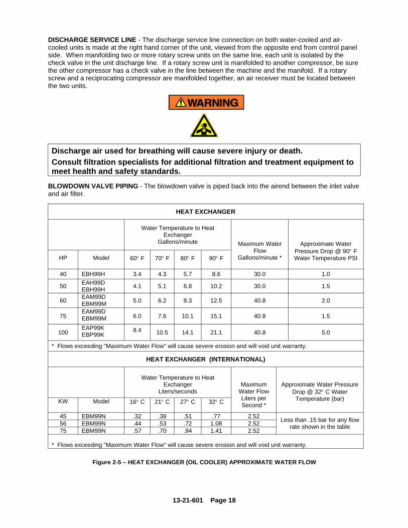
Discharge air used for breathing will cause severe injury or death. Consult filtration specialists for additional filtration and treatment equipment to meet health and safety standards.
BLOWDOWN VALVE PIPING - The blowdown valve is piped back into the airend between the inlet valve and air filter.
HEAT EXCHANGER
Water Temperature to Heat
Exchanger Gallons/minute
HP Model 60° F 70° F 80° F 90° F
Maximum Water Flow
Gallons/minute *
Approximate Water Pressure Drop @ 90° F Water Temperature PSI
40 EBH99H 3.4 4.3 5.7 8.6 30.0 1.0
50 EAH99D EBH99H 4.1 5.1 6.8 10.2 30.0 1.5
60 EAM99D EBM99M 5.0 6.2 8.3 12.5 40.8 2.0
75 EAM99D EBM99M 6.0 7.6 10.1 15.1 40.8 1.5
100 EAP99K EBP99K
8.4
10.5 14.1 21.1 40.8 5.0
* Flows exceeding "Maximum Water Flow" will cause severe erosion and will void unit warranty.
HEAT EXCHANGER (INTERNATIONAL)
Water Temperature to Heat
Exchanger Liters/seconds
KW Model 16° C 21° C 27° C 32° C
Maximum Water Flow Liters per Second *
Approximate Water Pressure Drop @ 32° C Water Temperature (bar)
45 EBM99N .32 .38 .51 .77 2.52 56 EBM99N .44 .53 .72 1.08 2.52 75 EBM99N .57 .70 .94 1.41 2.52
Less than .15 bar for any flow rate shown in the table
* Flows exceeding "Maximum Water Flow" will cause severe erosion and will void unit warranty.
Figure 2-5 – HEAT EXCHANGER (OIL COOLER) APPROXIMATE WATER FLOW

13-21-601 Page 19
AFTERCOOLER
Water Temperature to Heat Exchanger
Gallons/minute
HP Model 60° F 70° F 80° F 90° F
Maximum Water Flow
Gallons/minute *
Approximate Water Pressure Drop @ 90° F Water Temperature PSI
40 EBH99H .5 .7 .9 1.3 26.0
50 EAH99D EBH99H .7 .9 1.2 1.8 26.0
60 EAM99D EBM99M .8 1.0 1.4 2.1 26.0
75 EAM99D EBM99M 1.2 1.5 2.0 3.0 26.0
100 EAP99K EBP99K 1.7 2.1 2.8 4.1 26.0
Less than 1 PSI for any flow rate shown in the table
* Flows exceeding "Maximum Water Flow" will cause severe erosion and will void unit warranty.
AFTERCOOLER (INTERNATIONAL)
Water Temperature to Heat
Exchanger Liters/seconds
KW Model 16° C 21° C 27° C 32° C
Maximum Water Flow Liters per Second *
Approximate Water Pressure Drop @ 32° C Water Temperature (bar)
45 EBM99N .05 .06 .09 .13 3.47 56 EBM99N .08 .09 .13 .19 3.47 75 EBM99N .11 .14 .19 .28 3.47
Less than .1 bar for any flow rate shown in the table
* Flows exceeding "Maximum Water Flow" will cause severe erosion and will void unit warranty.
Figure-2-6 – AFTERCOOLER APPROXIMATE WATER FLOW
WATER PIPING (Water-Cooled Heat Exchanger Models Only) - On machines equipped with water-cooled heat exchangers, the water inlet and outlet connections are located in the unit base flange on the left side of the unit. It is mandatory that any water cooled unit be installed in a shelter heated to temperatures above freezing (32° F., 0° C).
The water source should be capable of supplying up to the maximum flow shown in Figure 2-5, Page 18, and Figure-2-6, page19, at a minimum pressure of 40 psig (2.8 bar); maximum allowable water pressure is 150 psig (10.3 bar). The water flow rates shown are approximate and a guide to sizing piping, cooling tower and other water system equipment.
CCCAAAUUUTTTIIIOOONNN

13-21-601 Page 20
The heat exchanger system is designed to operate with water inlet temperatures from 60° F to 90° F (16° C to 32° C) and a water outlet temperature not to exceed 110° F (43° C). If water cooler than 60° F is used, high water outlet temperatures (over 110° F, 43° C) will be experienced along with shortened heat exchanger life caused by tube fouling and corrosion. If water warmer than 90° F (32° C) is used, higher compressor oil inlet temperatures and high water usage will result.
Most water systems will require control of impurities: filtration, softening or other treatment. See Section 5, “Compressor Oil Cooler - Water-Cooled Heat Exchanger” for more information on the water system.
Figure 2-7 – SERIES PIPING
SERIES PIPING (Figure 2-7) - Water flow must be through aftercooler first for effective cooling of discharge air and is so piped on the standard water-cooled unit.
Figure 2-8 – PARALLEL PIPING

13-21-601 Page 21
PARALLEL PIPING (Figure 2-8, page 20) - A separate water control valve is required to control the discharge air temperature. If a remote (externally mounted) water-cooled aftercooler is piped in parallel with the heat exchanger, provide a separate water control valve for the aftercooler and pipe separate inlet water lines to both the aftercooler and heat exchanger. The water control valve is to be adjusted to maintain oil out of the heat exchanger within the 140° F to 150° F (60° C to 66° C) range regardless of inlet water flow or temperature as long as a minimum flow for a given temperature is met Figure 2-5, Page 18 and, page19. See Section 5 for adjustment instructions and maximum allowable lubricant temperature. ELECTRICAL WIRING - Standard Units – The compressor package is factory wired for all connections from the starter to the motor, for the horsepower and voltage specified on the order. The standard unit is supplied with open drip proof motors and a UL Type 4 control box. Totally enclosed motors are available as factory options. See “Location” paragraph on page 11, for distance to the nearest obstruction on the control box side of the package. Perform all wiring in accordance with the National Electrical Code (NFPA – 70) and any applicable local electrical codes. Wiring must be performed only by qualified electrical professionals.
Electrical shock can cause injury or death. Open main disconnect switch, lockout and tagout before working on control box.
GROUNDING - Equipment must be grounded in accordance with Section 250 of the National Electrical Code.
Failure to properly ground the compressor package could result in injury or death. Install ground wiring in accordance with the National Electrical Code and any applicable local codes.

13-21-601 Page 22
MOTOR LUBRICATION - Long time satisfactory operation of an electric motor depends in large measure on proper lubrication of the bearings. The following charts show recommended grease qualities and regreasing intervals for ball bearing motors. For additional information refer to the motor manufacturer’s instructions. The following procedure should be used in regreasing: 1. Stop the unit. 2. Disconnect, lockout and tagout the unit from the power supply. 3. Remove the relief plug and free hole of hardened grease. 4. Wipe lubrication fitting clean and add grease with a hand-operated grease gun. Only enough grease
should be added to replace the grease used by the bearing. Too much grease can be as harmful as insufficient grease. The grease cavity should be about 1/2 full.
5. Leave the relief plug temporarily off. Reconnect the unit and run for about 20 minutes to expel the
excess grease. 6. Stop the unit. Replace the relief plug. 7. Restart the unit.
Rotating machinery can cause injury or death. Open main disconnect, lockout and tagout power supply to starter before working on the electric motor.
ELECTRIC MOTOR GREASE RECOMMENDATIONS (-30° C to 50° C)
MANUFACTURER TRADE NAME
CHEVRON SRI #2
SHELL DOLIUM R
EXXON UNIREX #2
EXXON POLYREX
ELECTRIC MOTOR REGREASING INTERVAL
Type of Service
Typical
Rating
Relubrication Interval
Up to 150 HP (112 kW) 18 Months Standard One or Two Shift Operation
Above 150 HP (112 kW) 12 Months Up to 150 HP (112 kW) 9 Months
Severe Continuous Operation Above 150 HP (112 kW) 6 Months Up to 150 HP (112 kW) 4 Months
Very Severe Dirty Locations, High Ambient Temperature Above 150 HP (112 kW) 2 Months

13-21-601 Page 23
SECTION 3 STARTING & OPERATING PROCEDURES
PRESTART-UP INSTRUCTIONS - A new unit as received from the factory has been tested and then prepared for shipping only. Do not attempt to operate the unit until checked and serviced as follows: 1. Compressor Oil - Check the oil level in the reservoir. Add oil only if the oil level gauge reads in the
red “ADD OIL” range. Do not mix different type oils. The unit is shipped filled with Gardner Denver AEON 9000 SP Lubricating Coolant which is suitable for the first 8000 hours under normal operating conditions.
REPLACE OIL FILTER EVERY 1000 HOURS
Initial fill, or filling after a complete draining of the system, may show the oil level in the yellow “EXCESS OIL” range. After start-up, the oil will fall into the green operating range as system components are filled. If necessary, add oil to bring the level to the top of the green range as read when the unit is operating at full load and normal pressure. See Figure 5-7, page 82.
NNNOOOTTTIIICCCEEE
Regular maintenance and replacement at required intervals of the oil filter, air filter and air/oil separator is necessary to achieve maximum service and extended drain intervals of AEON 9000 SP synthetic lubricant. Use only genuine Gardner Denver filters designed and specified for this compressor.
Before removing the oil filler plug, always stop the unit and release air pressure, lockout and tagout the power supply to the starter. Failure to release pressure or properly disconnect the power may result in personal injury or death.
During unloaded operation and after shutdown, the system will partially drain back into the oil
reservoir and the oil level may read higher than when operating on load. DO NOT DRAIN OIL TO CORRECT; on the next loaded cycle or start, oil will again fill the system and the gauge will indicate the operating level.
2. Air Filter - Inspect the air filter to be sure it is clean and tightly assembled. Refer to Section 6, for
complete servicing instructions. Be sure the inlet line, if used, is tight and clean. 3. Coupling - Check all bolts and cap screws for tightness. See Section 7. 4. Piping - Refer to Section 2, “Installation", and make sure piping meets all recommendations.

13-21-601 Page 24
5. Electrical - Check the wiring diagrams furnished with the unit to be sure it is properly wired. See Figure 4-14 Page 43 thru Figure 4-20, page 56, for general wiring diagrams and Section 2, for installation instructions.
6. Grounding - Equipment must be properly grounded according to Section 250 of the National
Electrical Code.
Failure to properly ground the compressor package could result in controller malfunction.
7. Rotation - Check for correct motor rotation by jogging the motor. See “Unit Setup Adjustments” in
the Controller Operating and Service Manual. Compressor drive shaft rotation must be clockwise, standing facing the compressor sheave.
Operation with incorrect motor rotation can damage equipment and cause oil eruption from the compressor inlet. When checking motor rotation, induce minimum rotation (less than one revolution if possible). Never allow motor to reach full speed.
The compressor unit’s direction of rotation must be checked every time the compressor is reconnected to the power supply.
8. System Pressure – The discharge pressure of the unit is set at the factory. To change the
discharge pressure, set the controls to the desired load pressure. DO NOT EXCEED THE MAXIMUM OPERATING PRESSURE ON THE COMPRESSOR NAMEPLATE. See “Operation Adjustments” in the Controller Operating and Service Manual.
Operation at excessive discharge air pressure can cause personal injury or damage to equipment. Do not adjust the full discharge air pressure above the maximum stamped on the unit nameplate.
9. Operating Mode - Refer to Section 4 for detailed information on the control system. 10. Enclosure - Check for damaged panels or doors. Check all screws and latches for tightness. Be
sure doors are closed and latched.
CCCAAAUUUTTTIIIOOONNN
CCCAAAUUUTTTIIIOOONNN
CCCAAAUUUTTTIIIOOONNN

13-21-601 Page 25
The compressor starts and stops automatically. Automatic restarting can cause injury or death. Open, lockout and tagout main disconnect and any other circuits before servicing the unit.
STARTING THE UNIT - Observe the following starting procedures. Unit Cold - If the unit is a water-cooled heat exchanger model, open any manual water inlet valves wide open. Start the unit by pressing STOP / RESET, then press RUN. Since the unit is equipped with a minimum (65 psig, 4.5 bar) pressure discharge valve, no special procedure to maintain unit reservoir pressure is required. Unit Hot - No warm-up period is required. If the unit is a water-cooled heat exchanger model, open any manual water inlet valves wide open. Start the unit by pushing STOP / RESET, then press RUN DAILY CHECK - Refer to Section 8, “Maintenance Schedule,” page 79. STOPPING THE UNIT - Press “STOP / RESET” button. The oil reservoir will automatically blow down as the motor stops. If the unit is a water-cooled heat exchanger type, close any manual water inlet valves.

13-20-604 Page 26
Quick Start Guide
Operation of the AirSmart controller is easy. Simply select a Target Pressure and then press the Run
button to start the compressor, no other settings are required. The Target Pressure comes preset to 100 PSI from the factory. The Unload Pressure is preset to 110 PSI. If a different pressure setting is desired, the following steps can be used as a guide.
Setting the Target Pressure
The Target Pressure setting is used to set the operating point of the compressor. To make any adjustments in the operation of the compressor, the machine must be stopped and in the Ready
mode. Stop the compressor by pressing the Stop/Reset button. The front panel display should read “READY” on line 3.
Next, press the Enter button to access the Adjustment Menu tree Since the Target Pressure setting is under the Operation Adjustment menu, press Enter again to access that sub-menu
The Target Pressure is the second item in the Operation Adjustment sub-menu so press the Down
button to navigate to the Target Pressure setting.
0 PSI 75°F 10 HRS AUTOMATIC
READY NO SERVICE ADVISORY
ADJUSTMENT MENU OPERATION ADJUSTMENT
(SELECT SUB MENU)
OPERATION ADJUSTMENT LANGUAGE-LANGUAGE
ENGLISH (US) (SELECT PARAMETER)
OPERATION ADJUSTMENT TARGET PRESSURE
100 PSI (SELECT PARAMETER)

13-21-601 Page 27
To change the Target Pressure, press the Enter button to edit the value. A flashing cursor will appear covering the least significant digit in the Target Pressure value, use the Plus and Minus buttons to change its value. Use the Right and Left buttons to move the cursor to other digits in the Target Pressure value. When the desired Target Pressure value is displayed, press the Enter button to save the new value. Pressing the Stop/Reset
button will abort the change and restore the previous value. In order to save the changes made to parameters, press the Stop/Reset button to go back to the heading of the current menu and then press the Stop/Reset button again. If parameter changes have been made, the following screen will appear. To permanently save the changes that were made, press the Enter button. If the Stop/Reset button is pressed, the parameter changes will be lost the next time the compressor power is turned off.
Setting The Unload and Load Pressure After setting the Target Pressure, set the Unload and Load Pressures values in a similar fashion. The Unload pressure is the third item in the Operation Adjustment sub-menu so press the Down button to navigate to the Unload Pressure setting. The Unload Pressure will control at which pressure the compressor unload and stops. The Load pressure is the fourth item in the Operation Adjustment sub-menu so press the Down button to navigate to the Load Pressure setting. The Load Pressure will control at which pressure the compressor will startup again after unloading.
OPERATION ADJUSTMENT TARGET PRESSURE
100 PSI (EDIT PARAMETER)
OPERATION ADJUSTMENT UNLOAD PRESSURE
110 PSI (SELECT PARAMETER)
OPERATION ADJUSTMENT LOAD PRESSURE
100 PSI (SELECT PARAMETER)
STORE MODIFIED PARAMETERS?
STOP = NO ENTER = YES

13-21-601 Page 28
SECTION 4 CONTROLS & INSTRUMENTATION
GENERAL DESCRIPTION - The Gardner Denver Rotary Screw compressor is prewired with all controls, motor, and starter for the voltage and horsepower at the time of ordering. It is necessary only to connect the compressor unit to the correct power supply and to the shop air line (and to the appropriate water supply if water-cooled). A standard compressor unit consists of the compressor, oil reservoir, oil cooling system and filter, motor type as specified, UL TYPE 4 control box, and control components as described below. AIRSMART® OPERATION Operation of the "AirSmart" is dependent on selection of an operating mode from the controller keypad. Prior to starting, the STOP/RESET key must be pressed to place the controller into its READY state (as indicated on the display). Compressor operation may then be started by pressing the RUN key. While in any operating mode, the display will indicate the mode, and the operating light will be on. Press the STOP/RESET key at any time to stop the compressor under normal conditions. AUTOMATIC is the most common selected mode of operation, as it automatically will operate the compressor unit in the most efficient manner for the demand of the air system. Refer to the controller manual for descriptions of other modes. Detailed instructions for the controller are found in the “AirSmart” Controller Operating and Service Manual.
Automatic restarting or electrical shock can cause injury or death. Disconnect, lockout and tagout the unit from the power supply and any other circuits before servicing unit.
CONTROL DEVICES Controller - This compressor unit features the “AirSmart” controller, which integrates all the control functions under microprocessor control. Its functions include safety and shutdown, compressor regulation, operator control, and advisory/maintenance indicators. The keypad and display provide the operator with a logical and easily operated control of the compressor and indication of its condition. The controller is factory adjusted for the compressor package, but allows tuning for specific applications.

13-21-601 Page 29
Figure 4-1 – KEY PAD
Relief Valve - A pressure relief valve(s) is (are) installed in the final discharge line and set to approximately 120-125% of the unit’s full load operating pressure for protection against over pressure. Periodic checks should be made to ensure its (their) operation. The relief valve should be tested for proper operation at least once every year. To test the relief valve, raise the system operating pressure to 75% of the relief valve set pressure and manually open the valve with the hand lever. Hold the valve open for a few seconds and allow it to snap shut.
When the relief valve opens, a stream of high velocity air is released, resulting in a high noise level and possible discharge of accumulated dirt or other debris. Always wear eye and ear protection and stand clear of the discharge port when testing the relief valve to prevent injury.
Never paint, lubricate or alter a relief valve. Do not plug vent or restrict discharge.
CCCAAAUUUTTTIIIOOONNN
13-21-601 Page 30
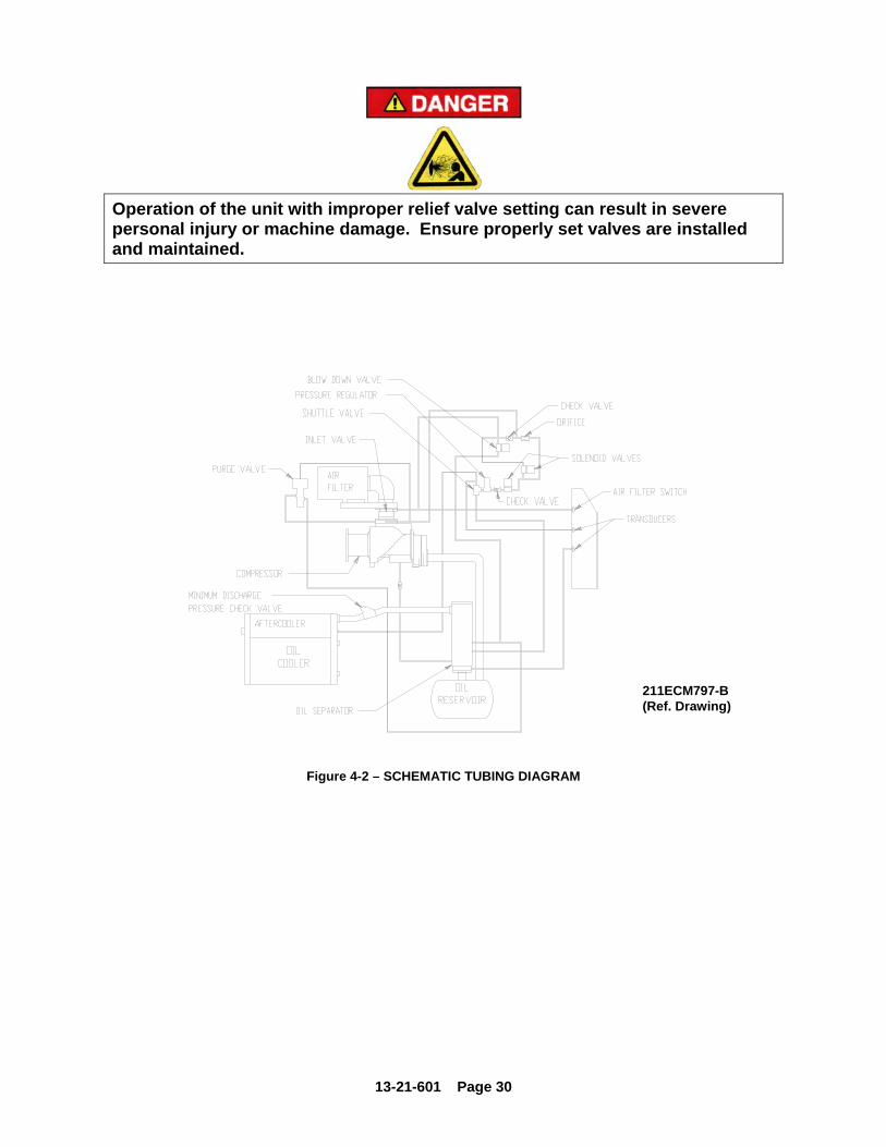
Operation of the unit with improper relief valve setting can result in severe personal injury or machine damage. Ensure properly set valves are installed and maintained.
Figure 4-2 – SCHEMATIC TUBING DIAGRAM
211ECM797-B(Ref. Drawing)

13-21-601 Page 31
Figure 4-3 – BLOWDOWN VALVE
Blowdown Valve (Figure 4-3) - This valve normally is used for control functions, but also serves to relieve reservoir pressure following a shutdown. The blowdown valve is a two-way solenoid valve which is piped into the oil reservoir outlet ahead of the minimum pressure valve. When the solenoid is de-energized, the valve opens and the coolant system is blown down. When the solenoid is energized, the valve closes to allow the coolant system to pressurize. A control air check valve is provided to ensure that the inlet valve is closed during blowdown. Oil Level Gauge (Figure 1-6, page 12) - This gauge is located on the oil reservoir and indicates the oil level. See Section 5 for information on how to correctly read the gauge and proper lubrication.
Figure 4-4 – MINIMUM DISCHARGE PRESSURE/CHECK VALVE
Minimum Discharge Pressure/Check Valve (Figure 4-4, page 31) - An internal spring-loaded minimum pressure valve is used in the final discharge line to provide a positive pressure on the coolant system of the compressor even if the air service valve is fully open to atmospheric pressure. This valve also functions as a check valve to prevent back flow of air from the shop air line when the unit stops, unloads, or is shut down.

13-21-601 Page 32
The valve incorporates a spring-loaded piston which maintains approximately 65 psig in the oil reservoir. When the air pressure on the upstream (reservoir) side of the valve rises above 65 psig, the spring is overridden and the valve opens to full porting. The valve does not require maintenance or adjustment. If the valve fails to function, check the valve stem O-ring for sealing, valve orifices for restriction, or valve and valve seat for burrs and dirt. The valve is adjustable within a small range. It is adjusted by a screw on the side of the valve. By turning the screw, the minimum pressure to open the valve increases. Conversely, backing it out decreases the minimum pressure required to open the valve. To service the valve, make sure all pressure is relieved, disconnect the unit from the power supply, lockout and tagout, then unscrew the valve cap from the body. The internal parts will come out after the cap has been removed. Repair kits are available from your local authorized Gardner Denver distributor.
Figure 4-5 – INLET VALVE
Inlet Valve, Figure 1-4 page 11 and Figure 4-5, page 32) - The Inlet valve restricts the inlet to control delivery and closes to unload the compressor. At shutdown, the inlet valve closes to prevent the back flow of air. The inlet valve position is controlled by air pressure in its piston cylinder, which is controlled by the “AirSmart” Controller through solenoid valves IVC and IVO. As Pressure to the piston is increased, the valve closes to restrict air flow and compressor delivery.
224ECM797-B (Ref. Drawing)

13-21-601 Page 33
Solenoid Valves IVC and IVO - These valves control position of the inlet valve in response to signals from the “AirSmart” Controller. With both valves de-energized, the normally open IVC valve allows control pressure to the inlet piston to close the valve. If IVC only is energized, the inlet valve is held in its current position. If both valves are energized, control pressure is relieved from the inlet piston to allow the valve to open. Pressure Regulator - The pressure regulator is used to supply a constant and low control pressure to prevent damage to the inlet valve from “slamming". The regulator should be set for 25-30 psig.
Figure 4-6 – SHUTTLE VALVE
Shuttle Valve (Figure 4-6) - Also known as a double check valve, the shuttle valve is a device which will take two (2) supply signals and allow the one with the highest pressure to pass through. The shuttle valve is used to provide control air pressure from either the reservoir or plant air system, as required during different operating conditions. Purge Air Valve - The purge valve is a normally closed two-way air actuated valve that admits purge air from the final discharge manifold to the compressor to counteract the oil knock that occurs in oil-flooded rotary screw compressors when they are completely unloaded with pressure in the oil reservoir. This valve is controlled by the same control pressure which controls the inlet valve.

13-21-601 Page 34
Figure 4-7 – TURN VALVE – ELECTRA-SAVER ONLY
Turn Valve (Electra-Saver only) (Figure 4-7)- The turn valve is a helical valve which, when rotated, opens and closes a series of ports cast into the compressor cylinder. When these ports are open, they direct some of the air which would otherwise be compressed back to the inlet, reducing both capacity and power consumption. Turn Valve Actuator (Electra-Saver only) - The turn valve actuator is a rotary rack and pinion device which positions the turn valve according to system demand. Filtered oil from the compressor sump is directed to the outboard end of the two actuating cylinders to move the rack and rotate the valve. Located on the ends of the cylinders are adjusting screws which limit the travel of the actuator. When looking at the rear of the compressor, the adjusting screw on the right on the compressor adjusts the fully closed (full-load) position of the valve. The full load position of the actuator may be checked by removing the adjusting screw at the unloaded end of the actuator (left side of the compressor) and using a rod to push the pistons to the full load position. The rod must be clean and free of burrs and scale. Take care not to scrape the cylinder walls when moving the pistons. Solenoid Valves TVC and TVO (Electra-Saver only) - These valves control the position of the turn valve in response to signals from the “AirSmart” controller. With both valves de-energized, equal pressure is applied to both ends of the actuator to hold it in its present position. If TVC only is energized, the right side of the turn valve actuator is exhausted to the compressor inlet cavity, causing the turn valve to move towards the full load position. If TVO only is energized, the left end of the turn valve actuator is exhausted to the compressor inlet cavity, causing the turn valve to move towards the unload position. See “AirSmart” Controller Manual, for a description of how the turn valve position is controlled during normal operation. System Pressure Transducer - This transducer is connected after the minimum pressure valve. It converts the pressure in the plant air system into an electrical signal for use by the “AirSmart” controller for modulation and control. Reservoir Pressure Transducer - This transducer is connected to the coolant system. Its signal is used to prevent loaded starts, monitor reservoir pressure, and monitor the condition of the air/oil separator. Air Filter Vacuum Switch - This switch is used to monitor air filter condition and alert the user if the filter requires service or replacement.
213ECM797-A(Ref. Drawing)

13-21-601 Page 35
Discharge Thermistor - This sensor is located directly in the compressor discharge. Its signal is used to monitor compressor temperature and shut down the compressor if a coolant problem is detected. Reservoir Thermistor - This sensor is located near the separator and is used to monitor temperature and shut down the compressor if high temperatures are detected. Emergency Stop Push-Button - This is a maintained push-button, and removes power from the controller outputs regardless of controller status. It is located on the upper section of the panel, next to the keypad. This should be used for emergency purposes only - use the keypad [STOP/RESET] for normal controlled stopping.
Automatic restarting or electrical shock can cause injury or death. Open, lockout and tagout main disconnect and any other circuits before servicing unit.
Power Supply - This device changes the incoming AC supply voltage to 24 volts DC for use by all unit control devices. For 575 volt AC units only, a control transformer is provided to supply 230-240 volts AC input to the power supply. A secondary fuse is provided on the control transformer. Refer to adjacent labeling for replacement information. Fuse Blocks - Two Class CC fuse blocks provide line side protection for the power supply and control transformer, as applicable. Terminal Strip - This provides connections for all 24 volt DC controlled devices not directly connected to the “AirSmart” controller. Fan Starter - The starter is used to provide control and overload protection for the cooling fan or the ventilation fan of water – cooled units with enclosure. Overload heaters should be selected and adjusted based on the motor nameplate amps and the instructions located inside the cover of the electrical enclosure. Three fuses are provided. Refer to adjacent labeling for replacement information. Main Starter - This starter is used to provide control and overload protection for the main drive motor. Wiring diagrams for typical full voltage applications are illustrated on pages 45 thru 50. For Wye Delta and less starter applications, refer to the wiring diagram included in each control box enclosure. Overload protection is provided for each motor on full voltage and Wye Delta applications. The overloads are adjustable and are factory set based on the motor nameplate amps and the instructions located inside the control box door. Less starter applications utilize a control relay for control of a remote mounted motor starter (not provided with compressor package). Wye-delta starters employ three contactors which are controlled sequentially to provide low current starting. For wye-delta starters, the motor nameplate amps must be first multiplied by 0.577 before using the heater table.

13-21-601 Page 36
COMPRESSOR CAPACITY CONTROL - TURN VALVE UNITS ONLY The capacity of the compressor is controlled by the action of the turn valve and the compressor inlet valve. The turn valve controls compressor delivery to match demands of 40% to 100% of the compressor’s maximum capacity. The inlet valve throttles to control compressor delivery to match demands of 0% to 40% of the compressors maximum capacity. Example with normal setting of 100 PSIG:
Compressor Delivery Capacity
Inlet Valve
Turn Valve
Discharge Manifold Pressure
Full Open Closed 100 70% Open 50% Open 100 40% Open Full Open 100 30% Closing Full Open 103 20% Closing Full Open 103 0% Closed Full Open 103

13-21-601 Page 37
Figure 4-8 – CONTROL SCHEMATIC – COMPRESSOR UNLOADED – CONSTANT SPEED MODE
EBH, EBM, EBP UNITS ONLY
225ECM797-B (Ref. Drawing)

13-21-601 Page 38
Figure 4-9 – CONTROL SCHEMATIC – COMPRESSOR AT FULL LOAD – CONSTANT SPEED MODE
EBH, EBM, EBP UNITS ONLY
226ECM797-B (Ref. Drawing)

13-21-601 Page 39
Figure 4-10 – CONTROL SCHEMATIC – COMPRESSOR UNLOADED – LOW DEMAND MODE OR AUTO MODE
EBH, EBM, EBP UNITS ONLY
227ECM797-B (Ref. Drawing)

13-21-601 Page 40
Figure 4-11 – CONTROL SCHEMATIC – COMPRESSOR AT FULL LOAD
EAH, EAM, EAP UNITS ONLY
214ECM797-B(Ref. Drawing)

13-21-601 Page 41
Figure 4-12 – CONTROL SCHEMATIC – COMPRESSOR FULLY UNLOADED – LOW DEMAND MODE SWITCH OFF
EAH, EAM, EAP UNITS ONLY
215ECM797-B(Ref. Drawing)

13-21-601 Page 42
Figure 4-13 – CONTROL SCHEMATIC – COMPRESSOR FULLY LOADED – LOW DEMAND MODE SWITCH ON
EAH, EAM, EAP UNITS ONLY
216ECM797-B(Ref. Drawing
13-21-601 Page 43
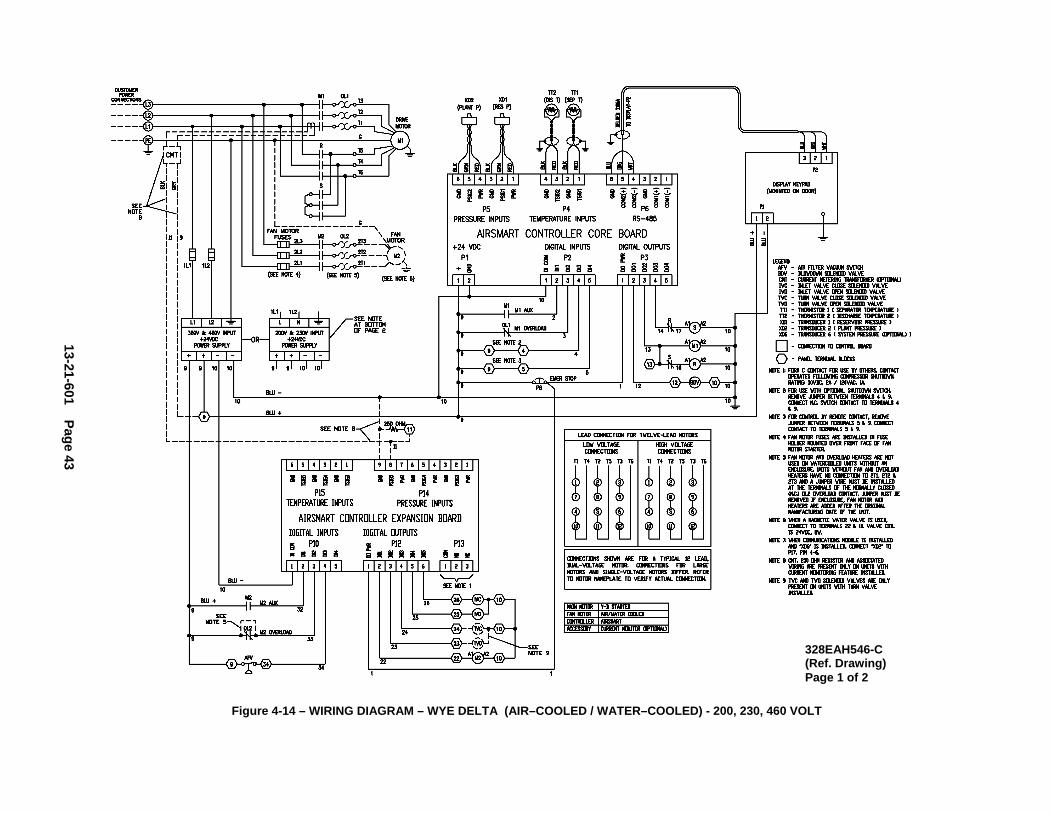
Figure 4-14 – WIRING DIAGRAM – WYE DELTA (AIR–COOLED / WATER–COOLED) - 200, 230, 460 VOLT
328EAH546-C(Ref. Drawing) Page 1 of 2
13-21-601 Page 44
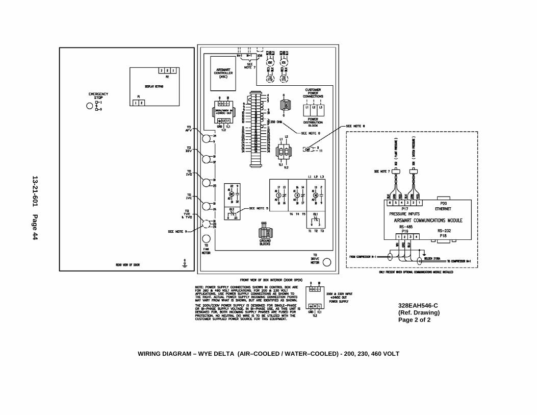
WIRING DIAGRAM – WYE DELTA (AIR–COOLED / WATER–COOLED) - 200, 230, 460 VOLT
328EAH546-C(Ref. Drawing) Page 2 of 2

13-21-601 Page 45
Figure 4-15 – WIRING DIAGRAM – WYE DELTA (AIR–COOLED / WATER–COOLED) - 575 VOLT
331EAH546-C(Ref. Drawing) Page 1 of 2

13-21-601 Page 46
WIRING DIAGRAM – WYE DELTA (AIR–COOLED / WATER–COOLED) - 575 VOLT
331EAH546-C(Ref. Drawing) Page 2 of 2

13-21-601 Page 47
Figure 4-16 – WIRING DIAGRAM – FULL VOLT (AIR–COOLED / WATER–COOLED) – 200 & 230 VOLT
329EAH546-C(Ref. Drawing) Page 1 of 2

13-21-601 Page 48
WIRING DIAGRAM – FULL VOLT (AIR–COOLED / WATER–COOLED) – 200 & 230 VOLT
329EAH546-C(Ref. Drawing) Page 2 of 2

13-21-601 Page 49
Figure 4-17 – WIRING DIAGRAM – FULL VOLT (AIR–COOLED / WATER–COOLED) – 460 VOLT
334EAH546-C(Ref. Drawing) Page 1 of 2

13-21-601 Page 50
WIRING DIAGRAM – FULL VOLT (AIR–COOLED / WATER–COOLED) – 460 VOLT
334EAH546-C(Ref. Drawing) Page 2 of 2

13-21-601 Page 51
Figure 4-18 – WIRING DIAGRAM – FULL VOLT (AIR–COOLED / WATER–COOLED) – 575 VOLT
332EAH546-C(Ref. Drawing) Page 1 of 2

13-21-601 Page 52
WIRING DIAGRAM – FULL VOLT (AIR–COOLED / WATER–COOLED) – 575 VOLT
332EAH546-C(Ref. Drawing) Page 2 of 2

13-21-601 Page 53
Figure 4-19 – WIRING DIAGRAM – LESS STARTER (AIR–COOLED / WATER–COOLED) – 200, 230, 460 VOLT
330EAH546-C(Ref. Drawing) Page 1 of 2

13-21-601 Page 54
WIRING DIAGRAM – LESS STARTER (AIR–COOLED / WATER–COOLED) – 200, 230, 460 VOLT
330EAH546-C(Ref. Drawing) Page 2 of 2

13-21-601 Page 55
Figure 4-20 – WIRING DIAGRAM – LESS STARTER (AIR–COOLED / WATER–COOLED) – 575 VOLT
333EAH546-C(Ref. Drawing) Page 1 of 2

13-21-601 Page 56
WIRING DIAGRAM – LESS STARTER (AIR–COOLED / WATER–COOLED) – 575 VOLT
333EAH546-C(Ref. Drawing) Page 2 of 2

13-21-601 Page 57
FIGURE 4-21 – WIRING DIAGRAM – WYE DELTA (AIR–COOLED / WATER–COOLED) – 200/230 VOLT
311EAM546-A(Ref. Drawing) Page 1 of 2

13-21-601 Page 58
WIRING DIAGRAM – WYE DELTA (AIR–COOLED / WATER–COOLED) – 200/230 VOLT
311EAM546-A(Ref. Drawing) Page 2 of 2

13-21-601 Page 59
FIGURE 4-22 – WIRING DIAGRAM – WYE DELTA (AIR–COOLED / WATER–COOLED) – 380/460 VOLT
310EAM546-A(Ref. Drawing) Page 1 of 2

13-21-601 Page 60
WIRING DIAGRAM – WYE DELTA (AIR–COOLED / WATER–COOLED) – 380/460 VOLT
310EAM546-A(Ref. Drawing) Page 2 of 2

13-21-601 Page 61
FIGURE 4-23 – WIRING DIAGRAM – WYE DELTA (AIR–COOLED / WATER–COOLED) – 575 VOLT
312EAM546-A(Ref. Drawing) Page 1 of 2

13-21-601 Page 62
WIRING DIAGRAM – WYE DELTA (AIR–COOLED / WATER–COOLED) – 575 VOLT
312EAM546-A(Ref. Drawing) Page 2 of 2

13-21-601 Page 63
FIGURE 4-24 – WIRING DIAGRAM – FULL VOLT (AIR–COOLED / WATER–COOLED) – 200 & 230 VOLT
314EAM546-A(Ref. Drawing) Page 1 of 2

13-21-601 Page 64
WIRING DIAGRAM – FULL VOLT (AIR–COOLED / WATER–COOLED) – 200 & 230 VOLT
314EAM546-A(Ref. Drawing) Page 2 of 2

13-21-601 Page 65
FIGURE 4-25 – WIRING DIAGRAM – FULL VOLT (AIR–COOLED / WATER–COOLED) – 380/460 VOLT
313EAM546-A(Ref. Drawing) Page 1 of 2

13-21-601 Page 66
WIRING DIAGRAM – FULL VOLT (AIR–COOLED / WATER–COOLED) – 380/460 VOLT
313EAM546-A(Ref. Drawing) Page 2 of 2

13-21-601 Page 67
FIGURE 4-26 – WIRING DIAGRAM – FULL VOLT (AIR–COOLED / WATER–COOLED) – 575 VOLT
315EAM546-A(Ref. Drawing) Page 1 of 2
13-21-601 Page 68
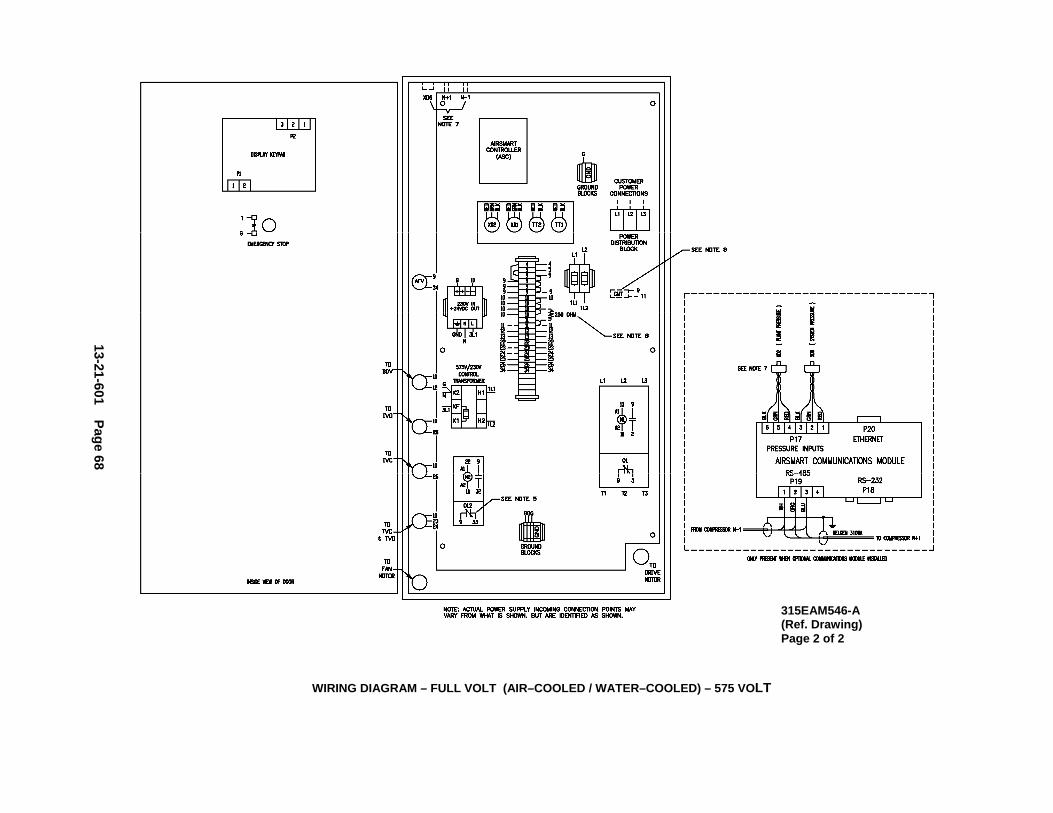
WIRING DIAGRAM – FULL VOLT (AIR–COOLED / WATER–COOLED) – 575 VOLT
315EAM546-A(Ref. Drawing) Page 2 of 2

13-21-601 Page 69
FIGURE 4-27 – WIRING DIAGRAM – LESS STARTER (AIR–COOLED / WATER–COOLED) – 200, 230, 380, 460 VOLT
316EAM546-A(Ref. Drawing) Page 1 of 2

13-21-601 Page 70
WIRING DIAGRAM – LESS STARTER (AIR–COOLED / WATER–COOLED) – 200, 230, 380, 460 VOLT
316EAM546-A(Ref. Drawing) Page 2 of 2
13-21-601 Page 71
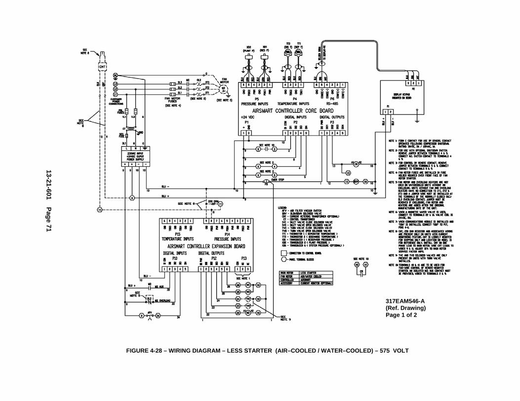
FIGURE 4-28 – WIRING DIAGRAM – LESS STARTER (AIR–COOLED / WATER–COOLED) – 575 VOLT
317EAM546-A(Ref. Drawing) Page 1 of 2

13-21-601 Page 72
WIRING DIAGRAM – LESS STARTER (AIR–COOLED / WATER–COOLED) – 575 VOLT
317EAM546-A(Ref. Drawing) Page 2 of 2

13-21-601 Page 73
SECTION 5 LUBRICATION OIL COOLER, OIL FILTER & SEPARATOR
COMPRESSOR OIL SYSTEM (Figure 5-3, page 76) cools the compressor, lubricates moving parts and seals internal clearances in the compression chamber. The oil inlet line is connected at the bottom of the oil reservoir. Air pressure in the oil reservoir forces oil through the oil cooler, thermostatic mixing valve, oil filter and into the compressor main oil gallery. The oil passes through internal passages for lubrication, cooling and sealing. The air/oil mixture is then discharged to the oil reservoir where a large part of the entrained oil drops out of the air stream; the air then passes through the final oil separator where most of the remaining oil is removed. The separated oil is returned to the compressor and the air passes to the final discharge line. RECOMMENDED LUBRICANT - Gardner Denver compressors are factory filled with AEON lubricants. These lubricants are formulated to the highest quality standards and are factory authorized, tested and approved for use in rotary screw compressors. AEON lubricants are available through your authorized Gardner Denver compressor distributor. OIL SPECIFICATIONS - The factory fill compressor lubricant is Gardner Denver AEON 9000 SP lubricating coolant which can be used for year-round operation. AEON 9000 SP is a synthetic, extended life lubricant which can extend lubricant change intervals up to 4 times that of a petroleum based lubricant. A lubricant analysis program for a periodic check of lubricant quality and remaining life can maximize the change interval.
Use of improper lubricants will cause damage to equipment. Do not mix different types of lubricants or use inferior lubricants.
Improper equipment maintenance with use of synthetic lubricants will damage equipment. For oil filter and oil separator change intervals, see Maintenance Schedule, page 80.
CCCAAAUUUTTTIIIOOONNN
CCCAAAUUUTTTIIIOOONNN

13-21-601 Page 74
HIGH TEMPERATURE OPERATION - Gardner Denver AEON 9000 SP lubricating coolant will operate at a sustained discharge temperature up to 210° F (99° C). When unusually high ambient air temperature is encountered, it will shorten the lubricant life; see Figure 5-7, page 82.
Air/oil under pressure will cause severe personal injury or death. Shut down compressor, relieve system of all pressure, disconnect, lockout and tagout power supply to the starter before removing valves, caps, plugs, fittings, bolts and filters.
High temperature operation can cause damage to equipment or personal injury. Do not repeatedly restart the unit after high temperature stops operation. Find and correct the malfunction before resuming operation.
All materials used in Gardner Denver compressor units are compatible with AEON 9000 SP Lubricating Coolant. Use caution when selecting downstream components such as air line lubricating bowls, gaskets and valve trim. AEON 9000 SP Synthetic Lubricant is not compatible with low nitrile Buna N or acrylic paints. AEON 9000 SP is compatible with most air system downstream components.
Material Safety Data Sheets (MSDS) are available for all AEON lubricants from your authorized Gardner Denver distributor or by calling 217-222-5400. MOISTURE IN THE OIL SYSTEM – In environments with normal operating temperatures and pressures and low relative humidity, the thermal mixing valve controls the oil temperature and prevents moisture accumulation in the oil. Unusual cooling of the oil reservoir, light duty cycles, high humidity, gross compressor over-sizing or malfunctions of the thermal mixing valve may result in moisture accumulation which is detrimental to compressor lubrication and may cause excessive oil carryover in the lubricant or compressor failure. Please note that the airend discharge temperature must be maintained a minimum of 10° F above the pressure dew point temperature in Figure 5-1, page 75. Failure to maintain the discharge temperature will cause moisture formation and compressor damage. The compressor must be observed to ensure that it is operating properly. The best method for detecting moisture is a disciplined lubricant sampling analysis program every 2,000 hours of operation. If moisture is observed in the oil reservoir, drain the moisture and correct the operating conditions to reduce moisture. See “Thermal Control (Thermostatic Mixing) Valve, page 85, “Water Shutoff Valve”, page 70 and “Compressor Oil System Check”, page 90, for additional system considerations. If moisture accumulation is observed in the lubricant, the best option is a higher temperature mixing valve, AEON 9000TH lubricating fluid and setting the high discharge temperature shutdown to 240° F (new controller software may be required), to prevent water from forming in the oil. Please contact Technical Services in MDC for part numbers, availability and controller software version verification (S/N required).
CCCAAAUUUTTTIIIOOONNN
CCCAAAUUUTTTIIIOOONNN

13-21-601 Page 75
Dew-Point Temperature vs. Ambient Temperature(100% Relative Humidity)
40
50
60
70
80
90
100
110
120
130
140
150
160
170
180
190
200
210
220
230
20 30 40 50 60 70 80 90 100 110 120
Ambient Temp. F
Dew
-Poi
nt T
emp.
F
100 psig
125 psig
150 psig
175 psig
Figure 5-1 – DEW POINT CHART °F
Figure 5-2 – DEW POINT CHART °C These charts are easily used by reading the ambient temperature along the bottom axis of the chart and then reading the appropriate pressure curve to determine the corresponding dew-point temperature on the left axis of the chart. The compressor discharge temperature must be maintained at a minimum of 10° F above this dew-point temperature to prevent condensation accumulation in the lubricant reservoir. These charts assume 100% relative humidity.
Dew-Point Temperature vs. Ambient Temperature(100% Relative Humidity)
20
30
40
50
60
70
80
90
100
110
-10 -5 0 5 10 15 20 25 30 35 40 45 50
Ambient Temp. C
Dew
-Poi
nt T
emp.
C
6.9 bar
8.6 bar
10.4 bar
12.1 bar

13-21-601 Page 76
Figure 5-3 – FLOW DIAGRAM – AIR/OIL SYSTEM
221ECM797-B(Ref. Drawing)

13-21-601 Page 77
Figure 5-4 – OIL FLOW DIAGRAM – REMOTE OVERHEAD MOUNTED COOLER
201EAP797-A(Ref. Drawing)
218ECM797-A(Ref. Drawing)

13-21-601 Page 78
REMOTE MOUNTED ELEVATED COOLER ASSEMBLY PROCEDURE - The Compressor package will be built and tested with the coolers mounted on the package. On enclosed units, the fan motor will be disconnected after test and the vent fan motor connected in its place. The vent fan will be mounted in the enclosure. A contactor (starter) will be shipped loose and remote mounted with the cooler by others upon start-up at the job site. The control box will be wired for remote elevated coolers at the factory.
NOTICE
All requirements of local codes should be followed. When connecting pipe fittings to the cooler, support the threaded coupling with a pipe wrench when tightening the connection. Use silicone sealant on all steel to aluminum threaded connections. All piping should be firmly supported to avoid strain on the cooler manifold and connections. Flexible connections should be installed in all interconnecting piping, adjacent to the cooler, to avoid transmitting piping weight or vibrations to the cooler elements. Before beginning installations, check to be sure that no debris or foreign matter remains in the couplings or cooler bodies. Be certain interconnecting piping is clean to avoid clogging the cooler passages.
Figure 5-5 – COOLER DRAIN DETAIL
AFTERCOOLER PIPING - At shutdown of the system, all units should be drained completely of condensate if there is any possibility of freezing or corrosion damage. To help remove the condensate, the cooler may be tapped per Figure 5-5, page 78, and a drain cock installed. After opening the drain cock, blow air into the cooler from a connection on the opposite side of the cooler. At the same time the connection on the drain side of the cooler should be plugged. The drain cock should be left open until the machines are ready for start-up.
Failure to remove condensate from an idle cooler in freezing temperatures will cause permanent cooler damage. Drain condensate after system shutdown. It is the owner/operator's responsibility to ensure that condensate has been drained and cooler dried out to prevent cooler damage.

13-21-601 Page 79
NOTICE
When removing the cooling module from the package for remote operation, do not use the flexible coupling (when supplied) between the air/oil separator housing and the minimum pressure/check valve. The discharge piping from the air/oil separator housing should be piped into the minimum pressure/check valve, then into piping to the cooler, with a flexible connection between the minimum pressure/check valve and aftercooler to keep the weight of the piping off of the cooler.
HEAT EXCHANGER (OIL) PIPING - All remote elevated cooler applications must be sent through Engineering for approval and for recommending pipe size. When the cooling module is removed from the package, the thermal mixing valve (H) remains on the package. Control group part number 200ECM4002 will be mounted on package at the factory. This group controls the oil stop valve as well as not allowing machine to run blown down. See Figure 5-4, page 77.
NOTICE Remote mounted elevated coolers have a maximum pipe length of 30 feet (9 M) (each way) and a maximum height of 20 feet (6 M) with a minimum of fittings. A remote elevated cooler form, J214, is required to be filled out. Customer Service will review all forms while in the quote stage. Customer Service will include the filled out J214 form on any special orders sent to Engineering.
NOTICE When removing the cooling module from the package for remote operation, the oil stop valve and the check valve that are shipped loose should be mounted as close to the compressor package as possible. Flexible connections should be used to keep the weight of the piping off of the cooler.
Kit number 200EAP4013 includes the oil stop valve, check valve and flanges and must be installed on all remote elevated coolers per Figure 5-4, page 77, and the following instructions: 1. Mount the check valve (90J113) as shown. 2. Mount the drain valves in the lowest section of the pipe on each side of the cooler connections. 3. Mount the oil stop valve (90AR243) in the line after the thermal mixing valve as shown. Modifications to the control lines will be made at the factory per 288ECM810 schematic. Air to the oil stop valve must come from the upper fitting in the separator housing, and then pass through the 3-way pneumatic valve. Control air to the valve must be from the line between the tee and the orifice in the blowdown muffler line per Figure 5-4, page 77. When the machine blows down, it will activate the pneumatic valve and it will shut off the air and vent the line between the pneumatic control valve and the oil stop valve to atmosphere. This will shut the oil stop valve and prevent excessive oil from running into the reservoir.

13-21-601 Page 80
Failure to install these parts or installations with pipe lengths and/or vertical runs outside the recommended limits, could result in high oil carryover and cause the machine to shut down on high discharge temperature. COLD AMBIENT OPERATION - See “Installation for Cold Weather Operation,” Section 2. ADDITION OF OIL BETWEEN CHANGES must be made when the oil level is in the red range on the gauge as read while the unit is on. To add oil, follow these steps: 1. Be sure the unit is completely off and that no air pressure is in the oil reservoir. 2. Disconnect, lockout and tagout the power supply to the starter. 3. Wipe away all dirt around the oil filler plug. 4. Remove the oil filler plug and add oil as required to return the oil level to the center of the green
range on the gauge. 5. Install the oil filler plug, restore power, run and check for leaks. DO NOT OVERFILL. The quantity required to raise the oil level from the red range center of the green range is shown in Figure 5-6, page 81. Repeated addition of oil between oil changes may indicate excessive oil carry-over and should be investigated.
Air/oil under pressure will cause severe personal injury or death. Shut down compressor, relieve system of all pressure, disconnect, lockout and tagout power supply to the starter before removing valves, caps, plugs, fittings, bolts and filters.
Compressor, air/oil reservoir, separation chamber and all piping and tubing may be at high temperature during and after operation.
Excessive oil carry-over can damage equipment. Never fill oil reservoir above the "FULL" marker.
LUBRICANT CHANGE PROCEDURE - Following are the primary steps to be completed when upgrading or changing the type of lubricant. 1. Thoroughly drain system:
- Drain oil from air end and cooler while hot. - Break low point connections and drain oil from pipe runs. - Dump oil from the filter and reinstall used filter.
CCCAAAUUUTTTIIIOOONNN

13-21-601 Page 81
2. Fill the system with a 50 percent charge of the new lubricant:
- Start the machine and stay there to observe. - Allow the machine to run about five minutes at temperature, or until temperature stabilizes, then
shut down.
3. Thoroughly drain the machine. 4. Change to a new filter and separator. 5. Fill the system with a full charge of the new lubricant, then reinstall drain plug. 6. Machine should then be run normally; however, total run time after the initial change out should be
50 percent of normal anticipated service life of the new lubricant.
- Drain all lubricant from the system, change the filter and separator, and replace with a full charge of the new lubricant.
7. Subsequent lubricant change outs should be at normal intervals. (See “Oil Change Interval” and
Figure 5-7, page 82). OIL LEVEL GAUGE (Figure 1-6, page 12 and Figure 5-6) indicates the amount of oil in the oil reservoir. Read oil level only when unit is on. In operation the oil level will fluctuate as the compressor loads and unloads. Add oil only when the oil is at the bottom of the red range on the gauge as read when the compressor is on. Drain oil only when the oil level is above the center of the green range on the gauge as read when the compressor is on.
Figure 5-6 – OIL LEVEL GAUGE
OIL CHANGE INTERVAL - Recommended oil change intervals are based on oil temperature. Figure 5-7, shows how the change interval is affected by temperature. When operating conditions are severe (very dusty, high humidity, etc.), it will be necessary to change the oil more frequently. Operating conditions and the appearance of the drained oil must be surveyed and the oil change intervals planned accordingly by the user. Gardner Denver offers a free oil analysis program with the AEON lubricants and we recommend a sample be sent in at 100 hours on a new unit.

13-21-601 Page 82
Discharge
Temperature AEON 4000
Change Interval AEON 9000 SP Change Interval
Up to 180° F (82° C) 4000 hrs. 8000 hrs.
180° F to 190° F (82° C to 88° C) 3000 hrs. 6000 hrs.
190° F to 200° F (88° C to 93° C) 2000 hrs. 4000 hrs.
200° F+ (93° C) 1000 hrs. 2000 hrs.
Figure 5-7 – OIL CHANGE INTERVAL
DRAINING AND CLEANING OIL SYSTEM
Air/oil under pressure will cause severe personal injury or death. Shut down compressor, relieve system of all pressure, disconnect, lockout and tagout power supply to the starter before removing valves, caps, plugs, fittings, bolts and filters.
Compressor, air/oil reservoir, separation chamber and all piping and tubing may be at high temperature during and after operation.
Always drain the complete system. Draining when the oil is hot will help to prevent varnish deposits and carry away impurities. To drain the system, use one of the following methods: 1. If the unit is not elevated high enough to use the oil reservoir drain line to drain oil, a small
hand, electric or air operated pump should be used to drain reservoir through the oil filler opening or from the drain valve.
2. If the unit is elevated so that the oil reservoir drain can be used, empty the oil reservoir through
the drain valve to a suitable container or sump. 3. If the drained oil and/or the oil filter element are contaminated with dirt, flush the entire system:
reservoir, oil cooler, mixing valve and lines. Inspect the oil separator elements for dirt accumulation; replace if necessary. If a varnish deposit exists, contact the factory for recommendations for removal of the deposit and prevention of varnish.
CCCAAAUUUTTTIIIOOONNN

13-21-601 Page 83
FILLING OIL RESERVOIR
Air/oil under pressure will cause severe personal injury or death. Shut down compressor, relieve system of all pressure, disconnect, lockout and tagout power supply to the starter before removing valves, caps, plugs, fittings, bolts and filters.
1. Be sure the unit is completely off and that no air pressure is in the oil reservoir. 2. Disconnect, lockout and tagout the power supply to the starter. 3. Wipe away all dirt around the oil filler plug. 4. Remove the oil filler plug and add oil as required to return the oil level to the center of the green
range on the gauge. 5. Install the oil filler plug and operate the unit for about a minute allowing oil to fill all areas of the
system. Check for leaks. 6. Shut down unit, allowing the oil to settle, and be certain all pressure is relieved. 7. Add oil, if necessary, to bring level to the center of the green range on the gauge. On unloaded operation and after shutdown some oil will drain back into the oil reservoir and the oil level gauge will read “FULL.” DO NOT DRAIN OIL TO CORRECT. On the next start, oil will again fill the system and the gauge will indicate operating at the proper level. DO NOT OVERFILL as oil carryover will result. The quantity of oil required to raise the oil level from “ADD” to “FULL” is shown in Figure 5-8. Repeated addition of oil between changes may indicate excessive oil carryover and should be investigated. Use only CLEAN containers and funnels so no dirt enters the reservoir. Provide for clean storage of oils. Changing the oil will be of little benefit if done in a careless manner.
Excessive oil carry-over can damage equipment. Never fill oil reservoir above the "FULL" marker.
40 & 50 HP 60, 75 & 100 HP
(45, 55 & 75 KW) Refill Capacity for Normal Oil Change 5.5 U.S. Gallons 8.5 U.S. Gallons
(32 Liters) Red to Yellow Range 1.25 U.S. Gallons 2.0 U.S. Gallons
(7.5 Liters)
Figure 5-8 – APPROXIMATE OIL SYSTEM CAPACITIES
CCCAAAUUUTTTIIIOOONNN

13-21-601 Page 84
COMPRESSOR OIL FILTER (Figure 5-3, Page 76) - This screw on oil filter is a vital part in maintaining a trouble-free compressor, since it removes dirt and abrasives from the circulated oil. The oil filter relief valve is located in the oil filter head. The relief valve opens in the event the element becomes dirty enough to block the flow of oil.
Improper oil filter maintenance will cause damage to equipment. Replace filter element every 1000 hours of operation. More frequent replacement could be required depending on operating conditions. A filter element left in service too long may damage equipment.
Use only the replacement element shown on the filter tag or refer to the parts list for the part number. Use the following procedure to replace the filter element. Do not disturb the piping.
Air/oil under pressure will cause severe personal injury or death. Shut down compressor, relieve system of all pressure, disconnect, lockout and tagout power supply to the starter before removing valves, caps, plugs, fittings, bolts and filters.
Compressor, air/oil reservoir, separation chamber and all piping and tubing may be at high temperature during and after operation.
1. Stop the unit and be sure no air pressure is in the oil reservoir. 2. Remove the spin-on element. 3. Clean the gasket face of the filter body. 4. Coat the new element gasket with clean lubricant used in the unit. 5. Screw the new element on the filter body and tighten by hand. DO NOT OVER TIGHTEN THE
ELEMENT. 6. Run the unit and check for leaks.
CCCAAAUUUTTTIIIOOONNN

13-21-601 Page 85
COMPRESSOR OIL COOLER - RADIATOR TYPE (Figure 1-5, page 11) - The oil cooler motor and fan is mounted on the oil cooler module; air is exhausted through the oil cooler and away from the unit. Do not obstruct air flow to and from the oil cooler. Allow a minimum of three (3) feet clearance around the cooler. Keep both faces of cooler core clean for efficient cooling of compressor oil.
Figure 5-9 – THERMOSTATIC MIXING VALVE ELEMENT
THERMAL CONTROL (THERMOSTATIC MIXING) VALVE (Figure 5-9) is installed in system as shown in Figure 5-3, page 76. This valve is used to control temperature of the oil in both air-cooled radiator and water-cooled heat exchanger type oil cooler systems. On start-up with unit cold, element is open to bypass, allowing oil to pass directly from the reservoir to compressor during warm-up. As oil warms, element gradually closes to the bypass allowing more of the oil from the cooler to mix with oil from the bypass. After the unit is warmed up, the mixing valve maintains oil injection temperature into the compressor at a minimum of 160° F (71° C). This system provides proper compressor warm-up and helps prevent moisture contamination of oil. To check element, heat in oil - it should be fully extended at 160° F (71° C). If unit shuts down due to high air discharge temperature, it may be that one or both thermostatic mixing valve elements (Figure 5-3, page 76) are stuck open. Remove mixing valve and clean all parts thoroughly when flushing the oil system.
Compressor, air/oil reservoir, separation chamber and all piping and tubing may be at high temperature during and after operation.
COMPRESSOR OIL COOLER - WATER-COOLED HEAT EXCHANGER (Figure 5-3, page 76) - The heat exchanger oil cooler is a multiple pass type, with water in the tubes and oil in the shell. The oil temperature is controlled by the thermal (thermostatic mixing) valve. The optional water control valve may be used to conserve water.

13-21-601 Page 86
It is mandatory that any water-cooled unit be installed in a shelter heated to temperatures above freezing (32° F, 0° C).
Oil cooler malfunction may be traced by checking pressure at oil inlet and outlet. At normal operating air service pressure (65 psig to 150 psig, 4.5 bar to 10.3 bar) with the unit warm, a pressure drop of 3 psi to 15 psi (.2 bar to 1 bar) can be expected between the oil inlet and the oil outlet. Water pressure drop from water inlet to outlet will vary with the inlet pressure and amount of water flowing. A normal pressure drop may range from 5 psi to 10 psi (.3 bar to .7 bar). Any change in the pressure drop from that normally held may indicate tube leakage or fouling and should be investigated. In many instances, the cooling water supply for the heat exchanger will contain impurities in solution and/or suspension. These substances can cause scale formation, corrosion and plugging of any water-cooled heat exchanger equipment. Disregarding the possibility that one or more of these conditions exist may result in increased maintenance and operation expense, reduced equipment life and emergency shutdown. It is strongly recommended that a reputable, local water treatment concern be engaged to establish the corrosion, scale forming and fouling tendency of the cooling water and take steps necessary to remedy the situation if a problem does exist. The need for water treatment may involve only filtration (screening) to remove debris, sand and/or salt in the cooling water supply. However, chemical treatment methods may be necessary in certain instances to inhibit corrosion and/or remove dissolved solids, to alter the water’s tendency to form scale deposits, or prevent the growth of microorganisms. The normal maintenance program for the unit should also include periodic cleaning of the tubes (water side) of the heat exchanger to remove deposits which enhance fouling and corrosion. Hex head zinc anodes are used in the return bonnet (opposite end to the water pipe connections) of heat exchangers to provide internal water system corrosion protection. These anodes should be inspected periodically and replaced when the zinc has been reduced to about 1/2 inch (13mm) in length.
Figure 5-10 – WATER CONTROL VALVE

13-21-601 Page 87
WATER FLOW CONTROL VALVE FOR HEAT EXCHANGER (Optional Equipment) (Figure 5-10, page 86) - The water flow control valve is adjustable to compensate for varying water inlet temperatures and pressures and is to be mounted in the water outlet line after the oil cooler (Figure 5-3, page 76). Use the compressor discharge air temperature gauge on the instrument panel in setting the flow control valve. The compressor discharge temperature must be maintained a minimum of 10° F (5° C) above the dew point temperature at the maximum anticipated ambient; refer to Figure 5-11, for the dew point temperature at the operating pressure and ambient temperature of the application.
Figure 5-11 – DEW POINT TEMPERATURE VS. AMBIENT TEMPERATURE
(100% RELATIVE HUMIDITY) To decrease water flow (increase compressor discharge air temperature) turn the adjusting screw from left to right, increasing spring tension. To increase water flow (decrease compressor discharge air temperature) turn the adjusting screw in the opposite direction. The groove at the lower edge of the adjusting screw is an index line for use with the index scale 0 to 8 in obtaining a desired setting. These valves must be handled with care and proper tools and techniques must be used when working on the valve. Care must be used when handling the capillary tube; a kink or break in the tubing or connections will make the valve inoperative. Never attempt to change capillary length. Excess capillary tube should be carefully coiled and placed so that damage will not occur in normal maintenance or traffic past the unit. If a leak develops through the packing, tighten the packing gland nut firmly with a wrench to reseat the packing around the valve stem, then back off the nut until loose, and finally retighten the nut finger tight. Tightening the packing nut too tight may cause erratic operation. An occasional drop of oil on the valve stem at the packing nut will prolong packing life. If valve malfunctions, check for bent or binding, paint or corrosion on valve stem, foreign material in valve, erosion, or thermal system (capillary) failure. If foreign material or scale is likely, the use of a strainer in the inlet water line is recommended.
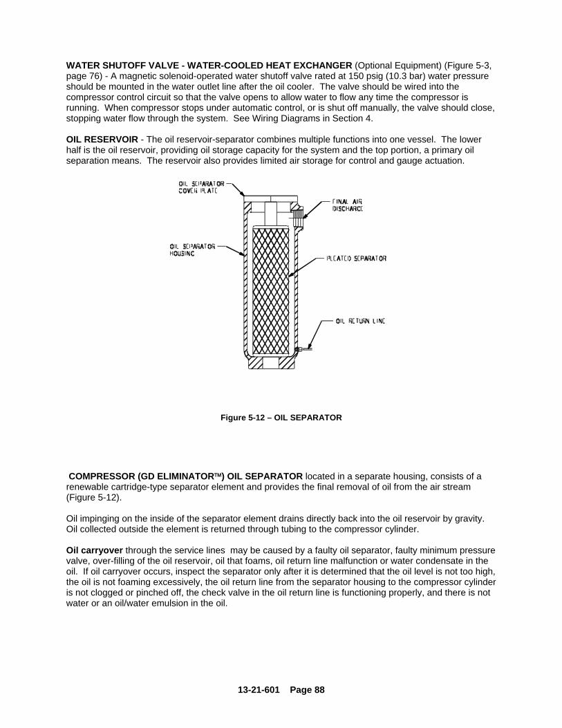
13-21-601 Page 88
WATER SHUTOFF VALVE - WATER-COOLED HEAT EXCHANGER (Optional Equipment) (Figure 5-3, page 76) - A magnetic solenoid-operated water shutoff valve rated at 150 psig (10.3 bar) water pressure should be mounted in the water outlet line after the oil cooler. The valve should be wired into the compressor control circuit so that the valve opens to allow water to flow any time the compressor is running. When compressor stops under automatic control, or is shut off manually, the valve should close, stopping water flow through the system. See Wiring Diagrams in Section 4. OIL RESERVOIR - The oil reservoir-separator combines multiple functions into one vessel. The lower half is the oil reservoir, providing oil storage capacity for the system and the top portion, a primary oil separation means. The reservoir also provides limited air storage for control and gauge actuation.
Figure 5-12 – OIL SEPARATOR
COMPRESSOR (GD ELIMINATOR™) OIL SEPARATOR located in a separate housing, consists of a renewable cartridge-type separator element and provides the final removal of oil from the air stream (Figure 5-12). Oil impinging on the inside of the separator element drains directly back into the oil reservoir by gravity. Oil collected outside the element is returned through tubing to the compressor cylinder. Oil carryover through the service lines may be caused by a faulty oil separator, faulty minimum pressure valve, over-filling of the oil reservoir, oil that foams, oil return line malfunction or water condensate in the oil. If oil carryover occurs, inspect the separator only after it is determined that the oil level is not too high, the oil is not foaming excessively, the oil return line from the separator housing to the compressor cylinder is not clogged or pinched off, the check valve in the oil return line is functioning properly, and there is not water or an oil/water emulsion in the oil.
13-21-601 Page 89
Oil carryover malfunctions of the oil separator are usually due to using elements too long, heavy dirt or varnish deposits caused by inadequate air filter service, use of improper oil or using oil too long for existing conditions. A ruptured or collapsed separator element is usually due to heavy dirt or varnish buildup in the filtering material. Excessive tilt angle of the unit will also hamper separation and cause oil carryover. Oil separator element life cannot be predicted; it will vary greatly depending on the conditions of operation, the quality of the oil used and the maintenance of the oil and air filters. The condition of the separator can be determined by pressure differential gauging or by inspection. Pressure Differential Gauging - The “CHANGE SEPARATOR” advisory will flash when the pressure differential across the oil separator reaches approximately 8 psid (.55 bar). Replace the oil separator element at this time. If ignored, the unit will shut down and the advisory will illuminate steadily when the pressure differential reaches 15 psid (1 bar).
Using an oil separator element at excessive pressure differential can cause damage to equipment. Replace the separator when the "Change Separator" advisory appears.
NOTICE A sudden drop of zero pressure differential or sudden heavy oil carryover may indicate a ruptured element.
Inspection - After removal of separator element, shine a light inside the element to reveal areas of heavy dirt or varnish deposits or breaks (ruptures) in the element media.

13-21-601 Page 90
Removal Of Oil Separator For Inspection Or Replacement:
Air/oil under pressure will cause severe personal injury or death. Shut down compressor, relieve system of all pressure, disconnect, lockout and tagout power supply to the starter before removing valves, caps, plugs, fittings, bolts and filters.
1. Be certain unit is completely off and that no air pressure is in the oil reservoir. 2. Disconnect, lockout and tagout power supply to the starter. 3. Remove screws holding the top plate to the separator housing. Lift the top plate from the
separator housing. 4. Lift the separator from the separator housing. 5. Inspect and/or replace the separator as necessary. Be sure the o-ring is not damaged. Before
installing (or reinstalling) any separator apply grease to the o-ring. Oil will be wiped off by the chamfer and the o-ring could be damaged.
6. Remove any gasket material adhering to top plate or separator housing, and install new gasket. 7. Lower the separator into the housing and center the separator on the chamfer. Press separator
down into the housing. Do not use excessive force as separator damage can occur. 8. Place the spacer on the indent in the separator. Seat the top plate to the separator, spacer and
separator housing. Install and tighten all cap screws. 9. Run the unit and check for leaks. COMPRESSOR OIL SYSTEM CHECK - The following readings are based on ambient temperature of 80° F (27° C) for air-cooled oil cooler and 80° F (27° C) inlet water on water-cooled oil cooler, with the system in good condition. Compressor should be at operating temperature at the time of checks. One-half hour of loaded operation is usually sufficient to reach level-out operating temperatures. Air and Oil Discharge Temperature - 165° F to 195° F (74° C to 91° C) - Read at gauge on the instrument panel or check with a thermometer at the discharge housing. Compressor Oil Inlet Temperature - 150° F to 160° F (66° C to 71° C) - Install a tee at the oil filter outlet and check with a thermometer. Oil Inlet Pressure - Check at the fitting in the line near the compressor oil inlet. With air receiver pressure at 100 psi (6.9 bar), oil inlet pressure should be 55 psig to 60 psig (3.8 bar to 4.1 bar).

13-21-601 Page 91
Oil Cooler Oil Pressure Differential (Air-Cooled Radiator) - Check differential across oil system by measuring oil inlet pressure as described above. Oil Cooler Oil Pressure Differential (Water-Cooled Heat Exchanger) – 2 psid to 25 psid (.1 bar to 1.7 bar) (65 psig to 150 psig, 4.5 bar to 10.3 bar receiver pressure) - Check that oil inlet pressure is correct or measure the differential between drains on the oil cooler shell. Oil Cooler Temperature Differential (Air-Cooled Radiator) - The oil temperature differential depends on the temperature of the air at the oil cooler fan and cleanliness of core faces. As ambient temperatures and core restrictions increase, the oil cooler outlet temperature will increase. The oil inlet temperature is approximately the same as air discharge temperature - see the gauge on the instrument panel. The outlet oil temperature may be checked by installing a tee at the oil filter outlet. Oil Cooler Temperature Differential (Water-Cooled Heat Exchanger) - The oil temperature differential depends on the inlet water temperature and the water flow rate permitted by the water flow control valve setting. The oil inlet temperature is approximately the same as the air discharge temperature - see the gauge on the instrument panel. The oil outlet temperature may be checked by installing a tee at the oil filter outlet. Oil Cooler Water Pressure Differential (Water-Cooled Heat Exchanger) - The water pressure differential through the heat exchanger will depend on the supply pressure, flow rate, cooler tube cleanliness and outlet pressure. The inlet and outlet water pressure may be checked at the pipe fittings supplied by the customer.

13-21-601 Page 92
SECTION 6 AIR FILTER
Figure 6-1 – HEAVY DUTY AIR FILTER
HEAVY-DUTY AIR FILTER (Figure 6-1) furnished as standard equipment on units with an enclosure is a heavy-duty washable element dry type air filter. The air filter must receive proper maintenance if maximum service is to be obtained from the unit. Establishing adequate and timely filter service is MOST IMPORTANT. An improperly maintained air filter can cause a loss of compressor air delivery. Filter Element - Clean every 50 to 150 operating hours depending on dust conditions.
NOTICE Use only genuine Gardner Denver air filter elements on Gardner Denver compressor units. Genuine parts are available through your authorized Gardner Denver distributor.
To service: 1. Remove the wingnut and pull out the filter element. 2. Visually inspect the element. If cleaning is not necessary, reinstall the filter element. If the element
requires cleaning, follow steps 3, 4 and 5. 3. Wash the element by soaking about 15 minutes in warm water with a mild non-sudsing detergent.
Rinse the element thoroughly with clean water; a hose may be used if the water pressure does not exceed 40 psig (2.8 bar).
4. Inspect the element for ruptures or cracks in the pleated media; replace the element if any are found.
Inspect the gasket on the bottom (outlet end) of the element; replace the entire element if the gasket is damaged. A spare element will keep down time to a minimum.
5. Allow the element to air dry COMPLETELY. Do not expose the element to heat over 150° F (66° C).
Install the element in the filter body and fasten securely with the wing nut.

13-21-601 Page 93
Do not oil this element. Do not wash in inflammable cleaning fluids. Do not use solvents other than water. Improper cleaning may damage the element.
NOTICE Never operate the unit without the element. Never use elements that are damaged, ruptured or wet. Never use gaskets that won't seal. Keep spare elements and gaskets on hand to reduce downtime. Store elements in a protected area free from damage, dirt and moisture. Handle all parts with care.
Filter Element Life - The element should be replaced after six (6) cleanings or if: 1. Visual inspection indicates a rupture, crack or pin hole in the pleated media. Inspection should be
done by placing a bright light inside the element. 2. Pressure drop through a filter with a freshly cleaned element is below three (3) inches (76 mm) of
water with the compressor running at full load - this would indicate a rupture or crack. Inlet Tube - Inspect the inlet screen and tube for dirt accumulation each time the filter is serviced. Clean the tube when required by ramming a clean dry cloth through the tube. Wipe the inside of the filter body to remove any dirt falling from the inlet tube before reinstalling the element. Causes of short element life include: severe dust conditions, infrequent servicing, improper cleaning, or contamination by oil or chemical fumes.
CCCAAAUUUTTTIIIOOONNN
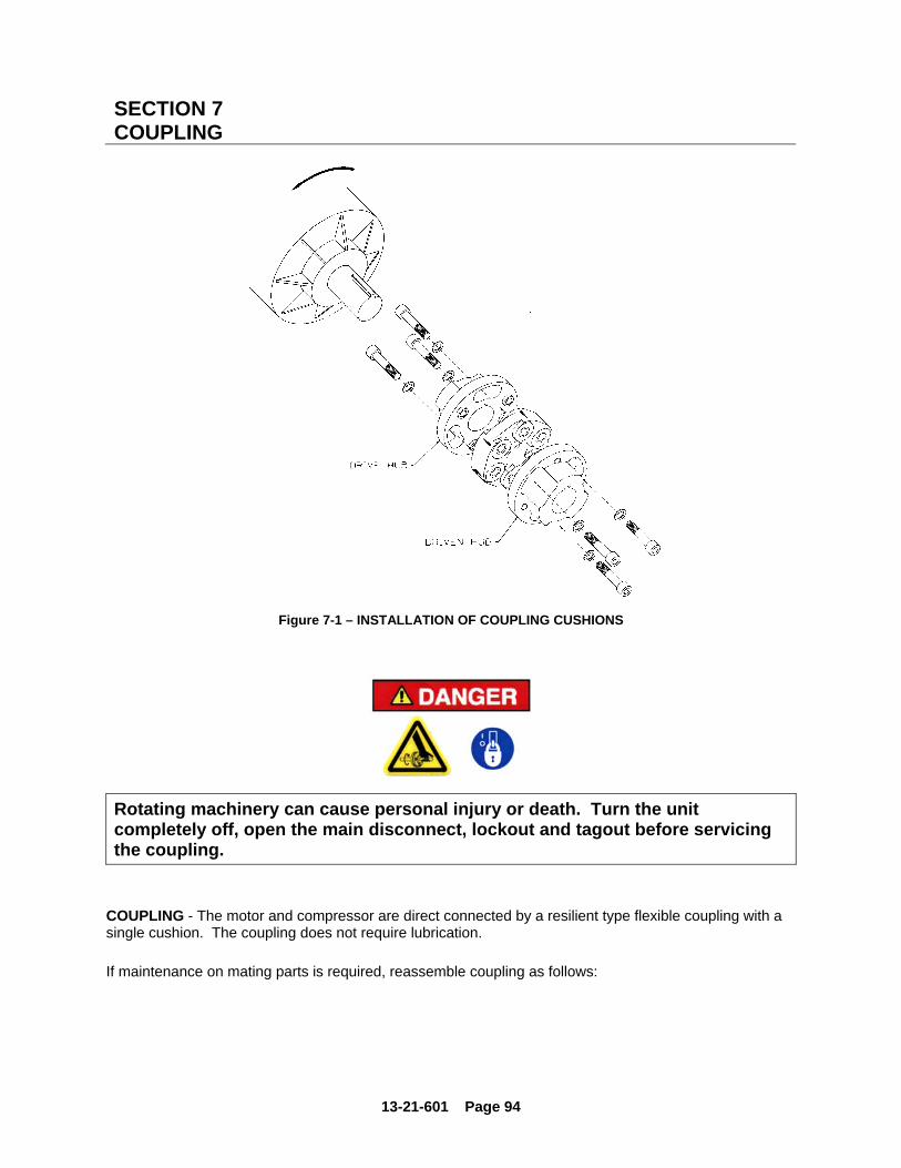
13-21-601 Page 94
SECTION 7 COUPLING
Figure 7-1 – INSTALLATION OF COUPLING CUSHIONS
Rotating machinery can cause personal injury or death. Turn the unit completely off, open the main disconnect, lockout and tagout before servicing the coupling.
COUPLING - The motor and compressor are direct connected by a resilient type flexible coupling with a single cushion. The coupling does not require lubrication. If maintenance on mating parts is required, reassemble coupling as follows:

13-21-601 Page 95
ASSEMBLY OF COUPLING ONTO THE AIREND AND MOTOR (Figure 7-1).
NOTICE Elements with non-uniform cross sections must be mounted with the rotation arrow on the coupling the same direction as the rotation arrow on the airend. Incorrect rotation will greatly decrease the torque carrying capacity of the coupling.
1. Slide coupling halves over shaft extensions. Lock compressor half (half with element pre-bolted to it)
down with set screw.
2. Assemble the motor to the compressor.
3. Working through the coupling guard opening, slide motor half into compressor half.
4. Place the supplied hardened washers under the cap screw heads and torque the screws down to the given specification. Keep the surfaces between the steel bushing in the elastomeric element, the hardened washer and the cap screw head free from dirt and apply a light oil or grease film to both sides of the hardened washer. This is very important since it will significantly reduce the rubber stresses around the metal bushings when torquing down the cap screws.
5. Check to see if element is centered between shaft ends. If element is centered, using the loctite supplied with the coupling, lock all set screws to 50 ft-lbs. If element is not centered, unlock set screws and slide coupling to center element between shaft ends and then, using the loctite supplied with the coupling, lock all set screws to 50 ft-lbs.
Rotating machinery can cause personal injury or death. Do not operate unit with either the coupling guard or the collar removed. All bolts and screws must be properly tightened.
ALIGNMENT - The coupling is permanently aligned by the flanges on the compressor and motor. Replacing Element:
NOTICE Elements with non-uniform cross sections must be mounted with the rotation arrow on the coupling the same direction as the rotation arrow on the airend. Incorrect rotation will greatly decrease the torque carrying capacity of the coupling.
1. Remove cap screws and washers. 2. Remove the element between the hubs.

13-21-601 Page 96
3. Apply a light oil or grease film to both sides of the hardened steel washer. This is very important,
since it will significantly reduce the rubber stresses around the metal bushings when torquing down the cap screws. Place the supplied hardened washers under the cap screw heads and torque the screws down to the torque rating in the assembly instructions supplied with the coupling. Keep the surfaces between the steel bushing in the elastomeric element, the hardened washer and the cap screw head free from dirt.
4. Check to see if element is centered between shaft ends. If element is centered, using the loctite
supplied with the coupling, lock all set screws (must have loctite, supplied with the coupling, applied to set screws) to 50 ft-lbs. If element is not centered, unlock the set screws and slide coupling to center element between shaft ends and then, using the loctite supplied with the coupling, lock all set screws to 50 ft-lbs.
Rotating machinery can cause personal injury or death. Do not operate unit with either the coupling guard or the collar removed. All bolts and screws must be properly tightened.

13-21-601 Page 97
SECTION 8 MAINTENANCE SCHEDULE
SERVICE CHECK LIST Air Filter - Operating conditions determine frequency of service. See “Air Filter", Section 6. Oil Separator - Operating conditions determine frequency of service. See “Compressor Oil Separator” in Section 5, for further details. Motor Lubrication - Refer to Section 2, and Maintenance Schedule Chart, page 79. Every 8 Hours Operation 1. Check the reservoir oil level - add oil if required. See Section 5. If oil consumption is high, refer to
“Excessive Oil consumption, page 100. DO NOT MIX LUBRICANTS. 2. Observe if the unit loads and unloads properly. 3. Check discharge pressure and temperature. 4. Check Panel LED’s for advisories. Every 125 Hours Operation 1. Check for dirt accumulation on oil/aftercooler core faces and the cooling fan. If cleaning is required,
clean the exterior fin surfaces of the cores by blowing compressed air carrying a nonflammable safety solvent in a direction opposite that of the cooling fan air flow. This cleaning operation will keep the exterior cooling surfaces clean and ensure effective heat dissipation.
Every 1000 Hours Operation 1. Change the oil filter element. Every 8000 Hours Operation 1. Change the compressor lubricant. UNDER ADVERSE CONDITIONS, CHANGE MORE
FREQUENTLY (refer to “Oil Change Interval”, page 97). Flush system if required. Every Year 1. Check the relief valve for proper operation. See Section 4. 2. Check shutdowns for proper operation.

13-21-601 Page 98
MAINTENANCE SCHEDULE
Maintenance Action As Indicated
by AirSmart Controller
Every 8 Hours
Every 125
Hours
Every 1000 Hours
Every 8000 * Hours
Every Year
Change Air Filter ...................................................... •
Change Oil Separator ............................................. •
Check Reservoir Oil Level ....................................... •
Check for Proper Load/Unload................................. •
Check Discharge Pressure/Temp ............................ •
Check Dirt Accumulation on Cooler ......................... •
Change Oil Filter Element ........................................ • •
Change Compressor Lubricant (AEON 9000 SP) *.. • •
Check Relief Valve................................................... • * See Oil Change Interval Chart, Figure 5-7, page 82, for specific lubricant life.
13-21-601 Page 99
SECTION 9 TROUBLESHOOTING
SYMPTOM POSSIBLE CAUSE REMEDY Compressor fails to start 1. Wrong lead connections. 1. Change leads.
2. Blown fuses in control box.
2. Replace fuse.
3. Motor starter overload tripped.
3. Reset and investigate cause of overload.
4. Pressure in reservoir. 4. Inspect blowdown valve.
5. Read error message on control panel
5. Take appropriate action.
6. Remote Contact is open (terminals 5 & 9).
6. Replace switch or jumper.
Compressor starts but stops after a short time
1. High discharge temperature.
1. See “High Discharge Air Temperature,” this section.
2. Blown fuse in starter/ control box.
2. Replace fuse (investigate if fuses continue to blow).
3. Motor starter overload heaters trips.
3. Reset and investigate cause of overload.
Compressor does not unload (or load)
1. Improperly adjusted control.
1. Refer to Controller Manual and adjust control.
2. Air leak in control lines. 2. Determine source of leak and correct.
3. Restricted control line. 3. Clean control lines.
4. Blowdown valve malfunction.
4 Repair, clean or replace valve.
Compressor cycles from load to unload excessively
1. Insufficient receiver capacity.
1. Increase receiver size.
2. Restriction in service piping
2. Inspect and clean service piping.
3. Restriction in control tubing.
3. Inspect and clean control tubing.
4. Plugged aftercooler. 4. Inspect and clean aftercooler.
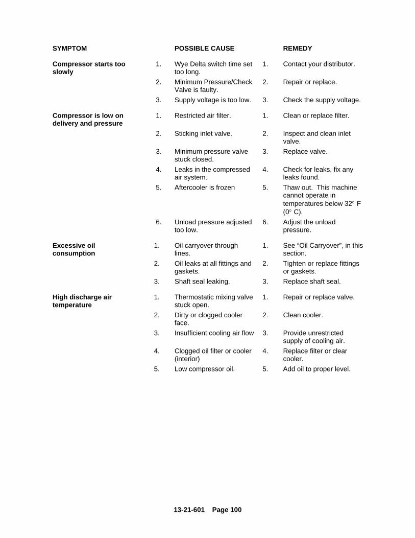
13-21-601 Page 100
SYMPTOM POSSIBLE CAUSE REMEDY Compressor starts too slowly
1. Wye Delta switch time set too long.
1. Contact your distributor.
2. Minimum Pressure/Check Valve is faulty.
2. Repair or replace.
3. Supply voltage is too low. 3. Check the supply voltage. Compressor is low on delivery and pressure
1. Restricted air filter. 1. Clean or replace filter.
2. Sticking inlet valve. 2. Inspect and clean inlet valve.
3. Minimum pressure valve stuck closed.
3. Replace valve.
4. Leaks in the compressed air system.
4. Check for leaks, fix any leaks found.
5. Aftercooler is frozen 5. Thaw out. This machine cannot operate in temperatures below 32° F (0° C).
6. Unload pressure adjusted too low.
6. Adjust the unload pressure.
Excessive oil consumption
1. Oil carryover through lines.
1. See “Oil Carryover”, in this section.
2. Oil leaks at all fittings and gaskets.
2. Tighten or replace fittings or gaskets.
3. Shaft seal leaking. 3. Replace shaft seal. High discharge air temperature
1. Thermostatic mixing valve stuck open.
1. Repair or replace valve.
2. Dirty or clogged cooler face.
2. Clean cooler.
3. Insufficient cooling air flow 3. Provide unrestricted supply of cooling air.
4. Clogged oil filter or cooler (interior)
4. Replace filter or clear cooler.
5. Low compressor oil. 5. Add oil to proper level.

13-21-601 Page 101
SYMPTOM POSSIBLE CAUSE REMEDY Oil carryover 1. Overfilling the reservoir. 1. Drain excess oil from
system.
2. Clogged, broken or loose oil return lines.
2. Tighten or replace faulty lines.
3. Ruptured oil separator element.
3. Replace element.
4. Loose assembly. 4. Tighten all fittings and gaskets.
5. Foam caused by use of incorrect oil.
5. Use Gardner Denver AEON 4000 or 9000 SP lubricating coolant.
6. Inoperative minimum pressure valve.
6. Replace seals in valve.
7. Operation at elevated discharge temperatures.
7. Reduce temperature. See “High Discharge Air Temperature”, this section.
8. Scavenge line check valve failure.
8. Replace check valve.
9. Water condensate in oil. 9. Check oil reservoir temperature and if low, change thermal mixing valve element to higher temperature.
NOTICE Gardner Denver factory remanufactured replacement compressor airend units are available from your authorized distributor, on an exchange basis, for all rotary screw compressor units.


For additional information contact your local representative or Gardner Denver, Inc. 1800 Gardner Expressway, Quincy, Illinois 62305 Telephone: (800) 682-9868 FAX: (217) 224-7814 Visit our Web Site: www.gardnerdenver.com
For additional information contact your local representative or Gardner Denver, Inc. 1800 Gardner Expressway, Quincy, Illinois 62305 Telephone: (800) 682-9868 FAX: (217) 224-7814 Visit our Web Site: www.gardnerdenver.com
Specification subject to change without notice. Copyright © 2011 Gardner Denver, Inc. Litho in U.S.A