electric 1/6 scale radio controlled dh-84 dragon-2teacupnavigation.net/handling and assembly... ·...
TRANSCRIPT
Electric 1/6 scale radio controlled DH-84 Dragon-2 By Rodger Farley, Columbia Maryland, USA
HANDLING and ASSEMBLY INSTRUCTIONS
Specifications
Wingspan = 94.66”, airfoil = 10.3% flat-bottomed with slight re-flexed trailing edge Length = 68.6” Wing area = 1700 square inches Weight = 14.5 lbs Wing loading = 19.6 oz/ square foot Static thrust ~ 10 lbs; Static thrust / weight ratio ~ 0.7 Power system
Motors = AXI 2826-10 brushless outrunners, 35-40 amps current each Props = APC 11x5.5 props Batteries = Poly-Quest TW 4350XP-45 Li-Po batteries (14.8 volt 4350 milli-amp-hour) Controllers: = Jeti Advance 77 Opto plus controllers. Turns on with the receiver being switched on / getting power, so there are no additional power switches to turn on/off, just the normal r/c receiver. Endurance ~ 8-10 minutes with a mixture of throttle settings Note for the power system: there are 2 of everything, completely independent twin engines. Brushless motors rely on the feedback of the individual motor to know when to commutate the windings, thus the independence. It’s possible therefore to have a single engine situation when one battery is weaker than the other, so play it safe. One servo in the fuselage powers all 4 ailerons via a mechanical push-push system making assemble a snap. If too much slack / backlash in the aileron connection eventually builds up then aileron flutter could be a future issue. Never seen/heard it on the plane so far, but little counter weights could be fashioned and attached to the ailerons to insure this never occurs. I’ve stuffed very small cotton balls into the push-push tubes to take up mechanical slack, which can be renewed if necessary (very small quantity of cotton). All rights reserved Rodger Farley 2014 [email protected]

Handling
This is a large model to hold, and so we start with the proper way to hold the starboard and port wing panels. From the pictures below one can see that there is a storage / support balsa stick that keeps the open end from bending inwards, protecting the outboard struts from damage. It also maintains some tension on the wires and keeps the shape for easy installation onto the inboard wing stubs. Shove the stick gently as shown to get the tension and secure wing separation. Make sure the ends are riding on the root rib and not the fabric cover!
Holding the wing panels is most easily done by holding the struts as shown in the next pictures.
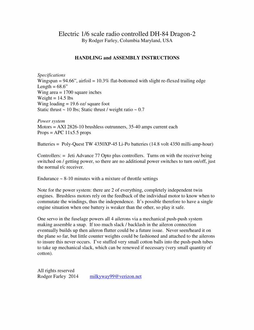
Next comes the best way to hold the fuselage. First shown is the “side grab”:
Hand spread out on bottom by the landing gear strut, fingers picking up on the edge.
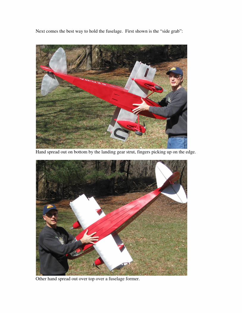
Other hand spread out over top over a fuselage former.

You can also fold your fingers over the landing gear struts, but not as flexible as the side grab. Not really recommended, but with care…
And of course the underhand grab with the back hand used for balance.

Rest Positions The Dragon can be rested on its nose as shown for inspection of the fuselage and wing bottom. This also gets you access to the bottom hatch (which can also be done from a 3-point attitude). The bottom photo shows the hatch removed.

It can also be turned upside down and rested on a pillow, but beware of what the vertical tail might be touching. In the case of the photo below the tail overhangs the table.
Also with the hatch removed. The hatch has a spring latch in the rear side of the hatch. Push the latch forward, then rocker the hatch up hinging on the front edge which has 2 alignment pins.
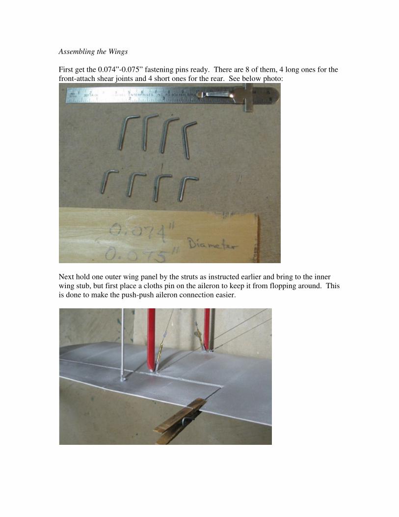
Assembling the Wings
First get the 0.074”-0.075” fastening pins ready. There are 8 of them, 4 long ones for the front-attach shear joints and 4 short ones for the rear. See below photo:
Next hold one outer wing panel by the struts as instructed earlier and bring to the inner wing stub, but first place a cloths pin on the aileron to keep it from flopping around. This is done to make the push-push aileron connection easier.

Note the connection lugs on the inboard wing stubs. There are corresponding slots on the outboard wing root rib face which you must insert the lugs while simultaneously aligning the aileron push-push pins with the mating push-push tubes protruding from the outboard wing root rib face.
Notice how the pins are lined up and now piloted by the inner diameter of the tubes.

This looks complicated, but with practice (and the clothes pin) you can assemble the whole plane in 2 minutes. I’ve seen comperable biplanes where the owner/builder will spend 30 minutes assembling everything. Start with aligning the bottom lugs into the slots while guiding the pins into the tubes. Once “primed” you can “hinge-in” the top lugs to the top slots while maintaining gentle pressure with your support hand that is holding the the outer wing struts in the approved manner. Don’t have too much angle as you work the bottom lugs on first or you might bend things you don’t want to get bent!!
Even the gaps between the top and bottom by small fore-aft wiggles using that outboard hand holding the struts while gentle pushing inwards. Keep doing this until the gaps on both top and bottom are closed.

With the gaps closed we insert the fastening pin, starting with the top front using the long variety pin. Wiggle it to insert it and make sure the wing gap is minimal so that the holes line up. There is a lead-in angle on the pin tips to help with this, but it has to be close enough for this alighment feature to work. You can of course remove the balsa support stick.

Wiggle it all the way down and point the “handle” rearwards.

Next connect the top rear pin using the short variety.
Next the front bottom with a long pin. This is a little more difficult as there are struts/wires in the way, so point the handle forwards to insert/wiggle and then twist to point rearwards. There is enough friction and flight loads on these pins that they never move, so no fear of it ever coming undone in the middle of flight. I do however inspect them after each 8-10 minute flight just to make sure. Never had to make an adjustment, but you never know, so between-flight inspections are still a good idea.
Lastly do the bottom rear with a short pin.

Battery Installation
First I hope you are keeping these powerful Lithium-polymer batteries stored safely, like in an ammo box.
Two batteries properly charged. These have the old Astro connectors on them. Riama now has Deans connectors on harness adapters on the electronic speed controls so your new batteries shoud come with the Deans connectors already mounted.

I’m showing this installation upside down for ease of pictures, but I usually do it with Riama in a 3-point attitude. Start with pushing the spring latch forward and hinging along the front hatch edge to remove the hatch. MAKE SURE THE RECEIVER SWITCH IS OFF (as can be seen in the photo).
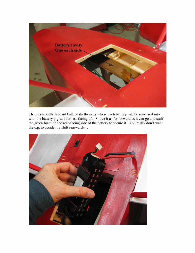
There is a port/starboard battery shelf/cavity where each battery will be squeezed into with the battery pig-tail harness facing aft. Shove it as far forward as it can go and stuff the green foam on the rear-facing side of the battery to secure it. You really don’t want the c.g. to accidently shift rearwards…
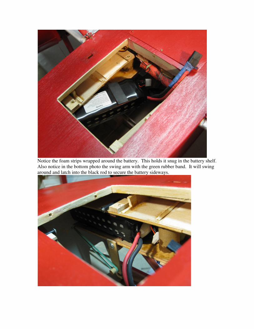
Notice the foam strips wrapped around the battery. This holds it snug in the battery shelf. Also notice in the bottom photo the swing arm with the green rubber band. It will swing around and latch into the black rod to secure the battery sideways.
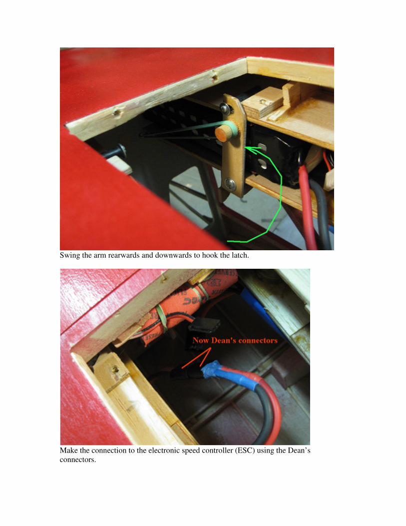
Swing the arm rearwards and downwards to hook the latch.
Make the connection to the electronic speed controller (ESC) using the Dean’s connectors.

Here the battery is secured by latch and green foam, and connected to ESC. Repeat process for other battery. Then replace the hatch by reverse steps: hook the forward edge by aligning the alignment pins on the hatch front frame with the holes in the hatch opening (you can see them in the above photo). Pull back the spring latch, hinge the hatch all the way in then release the spring latch. Make sure it secured as expected. When you turn on the receiver the electronic speed controllers come to life with 5 warning beeps. MAKE SURE YOUR R/C THROTTLE IS SET TO MINIMUM. They have been programmed to hold the prop in position when throttle is off to prevent windmilling (and the associated drag that comes with that in flight).

Inspection Ports
There are 2 inspection ports that can be accessed from the bottom of the fuselage. First is the main fuselage inspection panel which has 7 small screws (rear 2 not shown in this pic)
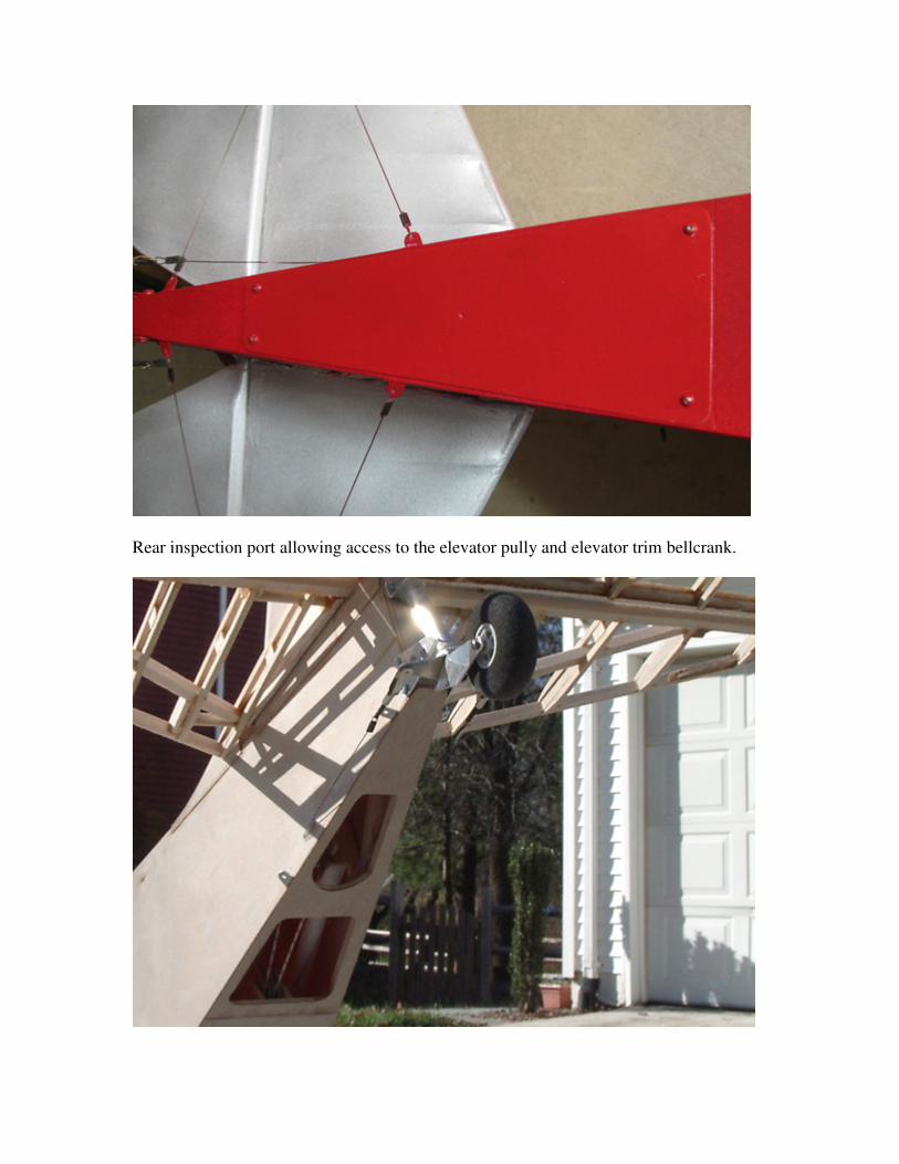
Rear inspection port allowing access to the elevator pully and elevator trim bellcrank.

New Features
On really hot days sometimes one electronic speed control (ESC) will shut down in the middle of a flight. That happens when one ESC exceeds a temperature threshold where it then shuts down without warning. Low and slow with the motors dragging it along is not the place to be when this happens! You must be vigilant to notice if there is unusual yawing, as that might indicate single engine operation. It can quickly turn into a boomerang (from simulated flight) if you don’t pull back the throttle and then set up for a mostly dead-stick landing. I have attempted to remedy the situation by cutting additional air vent grills on the bottom and by attaching a heat sink with silicone RTV to each of the 2 ESCs.
Interior picture viewed thru the side window showing port ESC (barely can see heat sink of starboard ESC on bottom left).
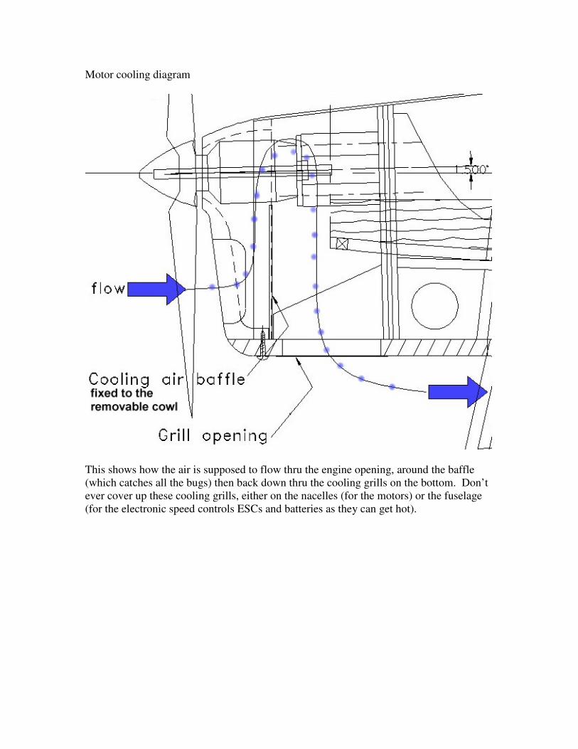
Motor cooling diagram
This shows how the air is supposed to flow thru the engine opening, around the baffle (which catches all the bugs) then back down thru the cooling grills on the bottom. Don’t ever cover up these cooling grills, either on the nacelles (for the motors) or the fuselage (for the electronic speed controls ESCs and batteries as they can get hot).

Wheel Pants
I was able to modify a pair of wheel pants from Fiberglass Specialties (HO-2WP Great Lakes wheel pants #128 for $35.00).
Add metallic spray paint and the result was pretty good.

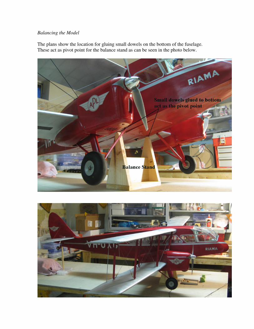
Balancing the Model
The plans show the location for gluing small dowels on the bottom of the fuselage. These act as pivot point for the balance stand as can be seen in the photo below.

Balancing is done with a full load of batteries, of course.
I used a small bubble level here with a ¼ x ¼ square piece of balsa shim to get the right angle.