electric actuators - britishvalves.com actuators ltd/5... · 2 | the actuator specialist auma is...
TRANSCRIPT

Information
Electric actuators
with fi eldbus interface

2 |
The actuator specialist
AUMA is one of the leading manufacturers of electric
actuators, actuator controls and valve gearboxes for the
automation of industrial valves. AUMA has more than
45 years of experience in research & development and
in manufacturing electric multi-turn and part-turn actua-
tors. AUMA manufactures in two German factories. Three
Service Centers, respectively in Cologne, Magdeburg and
Munich, have been set up to offer service support. World-
wide 1,700 employees belong to the AUMA group.
AUMA automates valves
AUMA actuators have stand up to a multitude of com-
plex requirements and operate in the most different appli-
cations - this is our daily business. The modular AUMA
design principle forms the basis of the long-term product
policy and offers the required flexibility to adapt actuator
manufacture to customer requirements.
Global presence
For this purpose, you have to know your markets well.
Thinking globally means acting regionally. A comprehen-
sive worldwide sales and service network ensures that
there is a competent local contact for every customer.
Single source supply
From product development to device testing, to final
inspection, AUMA offers continuous manufacturing and
quality assurance processes which are subject to constant
review.
Since 1964, AUMA has established an excellent brand
name in the world of actuators. Reliability and innovation
are concepts which are closely linked with AUMA. This is
above all to be credited to AUMA’s dedicated employees
who work devotedly on the future of the actuators.

| 3
10.0
3.10
Solutions for a world in motion
This brochure is intended for project engineers and
purchasing managers who would like to use AUMA actua-
tors with fieldbus interfaces. It offers an introduction to
fieldbus technology, an overview of the fieldbus systems
supported by AUMA and in particular the fieldbus-specific
features of AUMA actuators.
As early as the late 1980s, AUMA was actively involved
in the development of the fieldbus standards. In 1993, the
first AUMA actuator with fieldbus interface – Profibus FMS
– was available. AUMA was one of the pioneers of fieldbus
development for electric actuators.
Table of contents
The actuator specialist 2
Applications 4
Modular design - flexible applications 5
General fieldbus information 6
General fieldbus information - device integration 10
Profibus DP 12
Modbus RTU 14
DeviceNet 16
Foundation Fieldbus 18
AUMA actuators with fieldbus interfaces 20
SIMA:
ieldbus master and actuators from a single source 24
AUMA presales & after-sales 26
Links & literature 27
Certificates 28
Quality is not just a matter of trust 29
AUMA worldwide 30
AUMA does not only want to provide a fieldbus inter-
face: the features and functions defined by the corre-
sponding fieldbus protocol should be used to the full for
the benefit of valve automation. Further developments in
fieldbus protocols are thoroughly checked for their poten-
tial usability in actuators and implemented accordingly.
Due to AUMA’s modular product range, any AUMA
multi-turn, part-turn and linear actuator can be delivered
with fieldbus interface. The process integration of almost
any valve via fieldbus is possible.

4 |4 |
Power : Conventional power plants
(coal, gas, oil)
: Hydroelectric power plants
: Geothermal power plants
: Solar thermal power plants
: Biogas power plants
Water sector : Sewage treatment plants
: Water treatment plants
: Drinking water distribution
: Seawater desalination
: Steel construction for water resources
Industrial and special solutions: : Air conditioning
: Food industry
: Chemical/pharmaceutical industry
: Vessel and submarine shipbuilding
: Steel mills
: Paper industry
: Cement works
: Mining
Oil & gas : Exploration, offshore plants
: Refineries
: Distribution
: Gas tanks
: Tank farms
Applications

| 5
Modular design - fl exible applications
Individual solutions for individual challenges
There is no such thing as a standard actuator, even if
most processes appear to be standardised. Because all
industrial processes have their own specific particularities.
Therefore, AUMA always produces individually cus-
tomised solutions and only manufactures upon receipt of
order. The multitude of existing valve types, Distributed
Control Systems, application conditions and standards call
for flexible actuator and controls solutions. Always tailor-
made to suit the appropriate application whilst respecting
customer demands.
Modular design principles ensure flexibility in assembly, application and upgrading.
To preserve flexibility at any time, the AUMA product
range is produced as modular components.
■ AUMA actuator controls can be combined with any
actuator type. This way, uniform interfaces to the DCS
and a homogenous operation concept can be imple-
mented, even when combining different actuator types
and sizes.
■ The controls can be mounted separately from the
actuator on a wall bracket. For example, in case of
unfavourable mounting conditions, high ambient tem-
perature or to protect the electronics from vibration.

6 |
A S
S A
A S
[1][1]
A fieldbus is an industrial communication system, con-
necting a variety of field devices such as trans-
ducers (sensors), MOVs and actuators (drives) with a
control system. Fieldbus technology was developed in
the 1980s to replace the parallel wiring of binary signals,
which was common at that time, as well as analogue sig-
nal transmission by digital transmission technology. Today,
many different fieldbus systems with different characteris-
tics have become established on the market, e.g. Profibus,
Interbus, ControlNet, or CAN. Since 1999, fieldbus systems
worldwide have been standardised according to IEC 61158
“Digital data communication for measurement and control
– Fieldbus for use in industrial control systems”.
Structures in automation systems
At least one control system and often several trans-
ducers and MOVs are required to control a system. If the
control is to be performed electrically, the question is how
the transducers and the MOVs should be connected to the
control system. Two basic variants are possible:
■ A separate signal channel is established from the con-
trol system to each transducer and each MOV (parallel
wiring).
■ The signal exchange between control system and
several transducers and/or MOVs is implemented via a
common 2-wire cable (serial wiring).
The higher the level of automation of a plant or
machine, the larger the number of cables for parallel
wiring due to the increased number of input and output
points. Implementation, installation, commissioning and
maintenance become time consuming.
The demands placed on the cables are often high, e.g.
special cables have to be used for the transmission of
analogue values. Therefore, parallel wiring becomes an
essential cost and time factor in automation technology. In
comparison, serial wiring on the field level using so called
fieldbus systems have a considerable potential for simplifi-
cation.
[1] Parallel wiring
Multi-core cables for each device. This results in many
input and output subassemblies within the control cabinet
for connecting the field devices with the control system.
General fi eldbus information

| 7
A
S
AS SA
[2][2]
The fieldbus replaces the parallel trunk groups by a
single bus cable and connects all levels, from the field to
the process control level. Whatever the automation device,
e.g. programmable logic controls (PLC) from different
manufacturers or computer-based controls, the fieldbus
transmission medium links all components. The devices
can be located anywhere in the field. Fieldbus therefore
provides a powerful communication network for state-of-
the-art modernisation concepts.
Digital transmission
Only digital information is transmitted in fieldbus sys-
tems. Analogue setpoints or measured values are con-
verted into digital values before transmission via bus. The
digital signals are generally less susceptible to interference
than values subject to analogue transmission. Integral
verification mechanisms additionally improve transmission
security, e.g. by using checksums or acknowledging the
receipt of information to the sender.
[2] Serial wiring – fieldbus
A single 2-wire cable for all devices. The multitude of
input and output subassemblies are replaced by a single
fieldbus interface.

8 |
km
m
kBit/s MBit/s
[1][1]
Fieldbus systems have many advantages compared to parallel wiring
Reduced wiring saves time during planning and instal-
lation.
■ Cables, marshalling rack and dimensions of the control
cabinet will be reduced.
■ Reducing the components reduces the documentation
at the same time.
■ More information can be transferred using fewer
wires.
■ Self-diagnosis of the devices via fieldbus reduces
downtimes and maintenance times (asset manage-
ment).
■ Digitalisation of analogue values improves the protec-
tion against disturbance of signals.
■ Digitally collected measurement values and digitally
generated setpoints can be processed directly without
further signal conversion.
■ Open fieldbus systems standardise data transmission
and device integration of different manufacturers – the
user is not restricted by the standards of the individual
manufacturers.
■ Expansions or changes can easily be performed
guaranteeing flexibility and therefore security for the
future.
The following aspects have to be considered when implementing a fieldbus system.
■ Qualified personnel required for installation and com-
missioning.
■ Increased price of components with fieldbus func-
tions will be compensated by the potential savings of
fieldbus systems.
■ Special measuring and diagnostic equipment required.
■ Slightly increased response times (can usually be
ignored in process automation)
[1] Transmission rate/cable length
Most fieldbus systems specify several data transmission
rates which are indicated in kbit/s. Although it seems to
be reasonable to select the highest data transmission rate,
this is, however, at the expense of reduced cable length.
The higher the transmission rate and the longer the cables,
the higher the sensitivity and susceptibility to interference.
For each plant, the ideal compromise between cable
length and transmission rate has to be determined.
Therefore, a lower transmission rate has to be selected for
a sewage treatment plant with long distances than for ap-
plications where field devices are very close.
General fi eldbus information

| 9
Fieldbus cables/installation
Cable types
Data transmission via fieldbus cannot be implemented
on any cable. Cable types are specified for each field-
bus system. Due to the low data transmission rate, the
requirements for Foundation Fieldbus are comparatively
low; DeviceNet requires more complex cables as the bus
specification requires a separate supply voltage within the
same cable.
Installation
Data transmission on fieldbus systems are performed
with low signal levels, e.g. +/– 5 V. The installation has
to be performed thoroughly to ensure fault-free data
transmission. This applies to screening, equipotential
earth bonding, observance of the max. permissible cable
lengths, correct setting of the bus terminations and
addresses of the field devices. Observing the installation
guidelines ensures that all field devices on the bus can be
smoothly commissioned.
Fibre optics
As an alternative many fieldbus systems provide
data transmission via fibre optic cables (FO). Longer
distances can be covered with the cable types described
in the fieldbus specifications. An electric opto-coupler
converts the fieldbus signal into an optical signal and vice
versa.
Repeater/Extender
Generally speaking, repeaters or extenders are ampli-
fiers which extend the cable length of a fieldbus segment.
The section between the control system and the first re-
peater or between two repeaters is called a segment. The
number of repeaters or segments is limited. Furthermore
repeaters are also used:
■ to implement drop lines
■ to create another bus segment if the maximum
number of connectable devices per segment has been
reached
■ to provide galvanic separation between the segments
■ to refresh the timing of the data signals

10 |
General fi eldbus information - device integration
Commissioning
Contrary to conventional wiring where different signals
do not interfere with each other and do not require a
chronological order, fieldbus devices have to adhere to
strict organisation principles to ensure fault-free communi-
cation via the common data transmission medium.
This can be achieved by determining the communica-
tion parameters. During commissioning, the parameters
for each device connected are determined in the master.
During system start-up the parameters are sent to the field
devices. The programming of the parameters is based on
the electronic data sheets provided by the field device
manufacturers, e.g. GSD (Generic Station Description) for
Profibus DP.
The further development of fieldbus protocols and the
increasingly intelligent field devices provide the framework
for a variety of additional bus-supported functionalities.
This includes simplified device integration, remote pro-
gramming and diagnosis of all connected devices by the
bus itself via a central computer.
Commissioning example (Profibus DP)Commissioning example (Profibus DP)
R
[1][1] [2][2]
[3]
R
[3]
[1] The commissioning engineer requires the GSD files
of all field devices involved which can be downloaded
from the websites of the Profibus user organisation or of
the device manufacturers, for example. GSD files contain
information on the supported Profibus communication
parameters of the devices such as the data transmission
rates, data lengths…
[2] The commissioning engineer determines the commu-
nication parameters for all devices and stores them in the
Profibus DP master, in our example a PLC with Profibus DP
interface.
[3] When switching on the master and/or the field
devices, the determined communication parameters are
matched with the field devices. Process data may then im-
mediately be transmitted via the bus.
| 11
During operation
In addition to the central delimitation of communication
parameters, field device configuration can be influenced
online: the process behaviour, e.g. of an actuator, can be
changed from the control room.
The operating behaviour of the field devices can be
optimised during operation without gaining access to
the device. At the same time, diagnostic information is
available, helping to optimise the device parameters with
regards to an extended lifetime or enabling more efficient
maintenance.
The remote parameter setting is only possible if the
fieldbus supports the corresponding services, i.e. acyclic
DP-V1 services for Profibus DP. There are different con-
cepts for the various fieldbus systems.
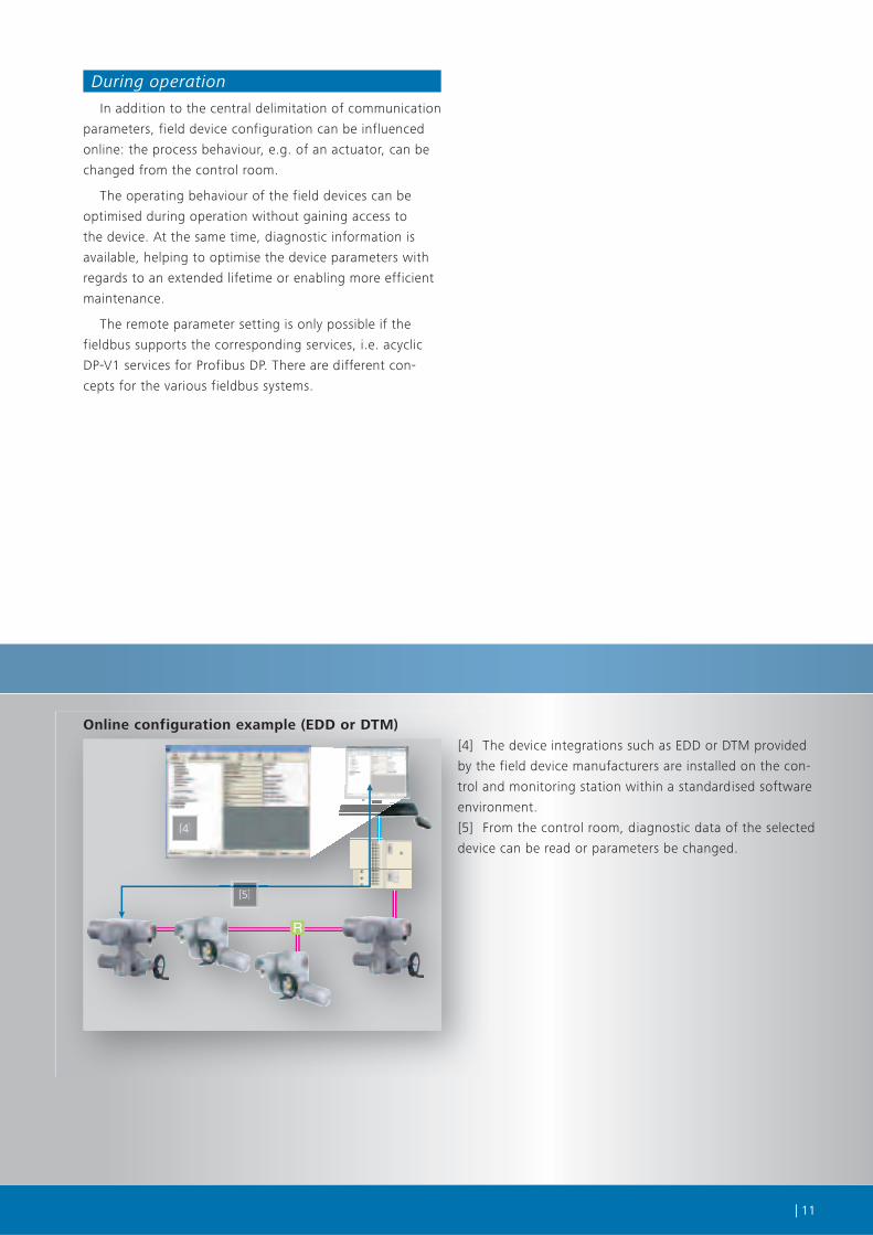
Online configuration example (EDD or DTM)Online configuration example (EDD or DTM)
R
[4] The device integrations such as EDD or DTM provided
by the field device manufacturers are installed on the con-
trol and monitoring station within a standardised software
environment.
[5] From the control room, diagnostic data of the selected
device can be read or parameters be changed.
[4][4]
[5][5]

12 |12 |
RR
[1][ ][1]
[2][2]
[3][3]
[4]
R
[4][4][4]
Profi bus DP
Profibus was developed from 1987 to 1989 within
the framework of a co-operation project (industry,
research institutes and the German federal office for
research) and was translated into the DIN standard
19245 (the standardisation process was continued
with the provisions of EN 50170 and IEC 61158).
Further successive developments included Profibus
DP, Profibus PA, Profibus DP-V1 and DP-V2, as well as
ProfiNet.
Topology
The basic structure for Profibus DP topology is the line.
Repeaters (R) can be used to implement drop lines to one
or more field devices.
Furthermore the repeaters can be used to connect
different bus segments. Profibus systems can thereby be
extended beyond the maximum cable length per segment.
[1] Control system
[2] Profibus DP Master (PLC)
[3] Field level with field devices
[4] Repeater
SA multi-turn actuators with AC integral controls in a gas station in China

| 13
Bus featuresDevelopment or notifi ed certifi ca-tion body
Profi bus International (PI) www.profi bus.com
Concept/communication principle Typically master-slave (for mono-master systems), additionally also master-master for multi-master systems. Use of request-response mechanisms for cyclic data transmission and DP-V1 services for acyclic data trans-mission.
Applications Predominantly in machine and plant engineering as well as production automation. Due to the quick data transmission and the, in principle, simple and robust physical data transmission system (RS-485), Profi bus DP can be used for various applications.
Versions Profi bus FMS, (FMS = Fieldbus Message Specifi cation), the fi rst Profi bus version, is rarely used at the fi eld level today. Profi bus DP (DP = Decentral Periphery), often called Profi bus DP-V0 today, cyclic data transmission for quick data exchange. Profi bus DP-V1, introduction of special DP-V1 services for acyclic data transmission (programming and device diagnosis via Profi bus). Profi bus DP-V2, a generic term for further Profi bus functions such as Isochron Mode (IsoM), Data Exchange Broadcast (DxB), time synchronisation (Time_Stamp), redundancy concept (redundancy) as well as upload and download. Profi bus PA (PA = Process Automation), a version which has been specially adapted to the requirements of process engineering, among others, to make the bus intrinsically safe for the use in plants in potentially explosive atmospheres. Profi Net, Profi bus based on Ethernet technology. AUMA actuators currently support Profi bus DP-V0, DP-V1 and DP-V2.
Physical layer RS-485,alternatively: FO
Maximum number of devices 126 (125 fi eld devices and a Profi bus DP master); without repeaters, a maximum of 32 devices per Profi bus segment
Typical number of devices Depends on the plant; typically 10 – 70 devices; for more devices, a second Profi bus DP network is usually installed.
Typical bus cycle time approx. 140 ms, for 30 actuators, the usually required process data (4 bytes input and 4 bytes output) and at 93.75 kbit/s
Data transmission rates of the bus 9.6 kbit/s to 12 Mbit/sRecommended baud rate: 93.75 kbit/s (if required: also 187.5 kbit/s). For these transmission rates, the maxi-mum cable length is reached at considerable transmission speeds. AUMA devices support transmission rates up to 1,5 Mbit/s.
Max. cable lengths without repeater
max. 1,200 m (for baud rates exceeding 187.5 kbit/s), 1,000 m at 187.5 kbit/s 500 m at 500 kbit/s , 200 m at 1.5 Mbit/s
Max. cable lengths with repeater approx. 10 km (only applies to baud rates exceeding 500 kbit/s), approx. 4 km (at 500 kbit/s) approx. 2 km (at 1.5 Mbit/s) The maximum cable length which can be implemented depends on the type and the number of repeaters.Usually, a maximum of 9 repeaters can be used in a Profi bus DP system.
Redundancy concepts Under the generic term of the Profi bus DP-V2 services, there is a slave redundancy specifi cation (2.212). This specifi cation stipulates the behaviour of a redundant Profi bus DP slave in detail. AUMA actuators are optionally equipped with a redundant Profi bus DP interface. Today, many DCS do still not support redundancy or have their own redundancy concepts. Current redundant solutions have to be matched in the run-up to commissioning.
Device integration/remote program-ming of the slaves
Remote programming is done using the acyclic Profi bus DP-V1 services. The device integration is imple-mented - using an EDD (in combination with Simatic PDM in Siemens process control systems). - using a DTM (in combination with an available FDT interface in the process control system) Both technologies are supported by AUMA.
Fieldbus termination The RS-485 specifi cation stipulates termination resistors at the beginning and at the end of each RS-485 segment. The resistor network has to be supplied with 5 V DC. On the master level, the supply voltage is provided by the master and on the fi eld level by the fi eld devices. AUMA products provide these fi eldbus termination resistors and do not require external termination resistors.

14 |14 |
RR
[1][ ][1]
[2][2]
[3][3]
[4]
R
[4][4][4]
Modbus RTU
In 1979, Modbus was developed by Gould-Modi-
con (today Schneider Electric) and has turned into a
de facto standard.
AUMA fieldbus actuators in a waste water treatment plant in Dublin, Ireland
Topology
The basic structure for Modbus RTU topology is the
line structure. Repeaters (R) can be used to implement drop
lines to one or more field devices.
Furthermore, the repeaters are used to connect differ-
ent bus segments. Thus, Modbus systems can be extended
beyond the maximum cable length per segment.
[1] Control system
[2] Modbus RTU Master (PLC)
[3] Field level with field devices
[4] Repeater

| 15
Bus featuresDevelopment or notifi ed certifi ca-tion body
Modbus IDA www.modbus.org
Concept/ communication principle
Master-slave with query-response mechanisms for data exchange. For Modbus, there is no distinction between cyclic and acyclic data exchange in both cases, the same mechanisms are used. There is only one master which is allowed to send messages without external request. The connected Modbus devices may acknowledge the received messages or send messages to the master on request of the latter.
Applications Predominantly in plant engineering where the real-time requirements on the response times are lower. Versions
Modbus ASCII, each byte of a telegram is transmitted using two ASCII characters; suitable for applications with a low process data level Modbus RTU, each byte of a telegram contains 2 hexadecimal characters Modbus Plus, extended Modbus protocol (contains two additional protocol layers such as HDLC level, MAC level and LLC level) Modbus TCP/IP, Modbus based on Ethernet technology AUMA actuators support Modbus RTU.
Physical layer RS-485, alternatively: FO
Maximum number of devices
247 fi eld devices and a Modbus RTU masterWithout repeaters, a maximum of 32 devices per Modbus segment
Typical number of devices Depends on the plant, typically 10 – 70 devices for more devices, a second Modbus network is usually installed.
Typical bus cycle time Approx. 850 ms, for 30 actuators, the usually required process data (3 input registers) and at 38.4 kbit/s
Data transmission rates of the bus 0.3 kbit/s to 38.4 kbit/s Max. cable lengths without repeater max. 1,200 m
Max. cable lengths with repeater
approx. 10 kmThe maximum cable length which can be implemented depends on the number of repeaters. This kind of cascadability depends on the repeater type; usually a maximum of 9 repeaters can be used in a Modbus system.
Redundancy concepts
There is no redundancy specifi cation for Modbus RTU.AUMA actuators are optionally equipped with a redundant Modbus RTU interface. Today, may DCS do still not support redundancy or have their own redundancy concepts. Current redundant solutions have to be matched in the run-up to commissioning.
Device integration/remote program-ming of the slaves
Modbus has no special communication services for the transmission of parameters available services are queried acyclically. Currently, there is no device integration specifi ed for Modbus; this means that each para-meter request as well as the corresponding parameter representation has to be programmed manually in the process control system.
Fieldbus termination The RS-485 specifi cation stipulates termination resistors at the beginning and at the end of each RS-485 segment. The resistor network has to be supplied with 5 V DC. On the master level, the supply voltage is provided by the master, on the fi eld level by the fi eld devices. AUMA products provide these fi eldbus termi-nation resistors and do not require external termination resistors.

16 |16 |
Thick cable Trunk line
Thin cable
Drop line
E
[1][1]
[2][2]
[3][3]
[4][4] [5]
E[5]
DeviceNet
DeviceNet was developed in 1993 by Allen-Brad-
ley; the development of the CAN protocol by Bosch,
which is the underlying protocol, started as early as
1983.
AC actuator controls on wall brackets in a copper mine in Chile
Topology
The basic structure for DeviceNet topology is the line
structure; drop lines are explicitly permitted as long as the
defined constraints are not exceeded.
In DeviceNet fieldbus systems, trunk lines are usually
implemented with thick cables. Thin cables are used for
optional drop lines.
When using extenders, DeviceNet systems can be
extended beyond the maximum cable length per segment.
[1] Control system
[2] DeviceNet Master (PLC)
[3] Field level with field devices
[4] T type
[5] Extender

| 17
Bus featuresDevelopment or notifi ed certifi ca-tion body
Open DeviceNet Vendor Association (ODVA) www.odva.org
Concept/ communication principle
DeviceNet is an object-oriented bus system operating according to the Producer-Consumer procedure. DeviceNet nodes can be client (master), server (slave) or both. Client and server can be producer, consu-mer or both. Each DeviceNet node can produce or consume data on the bus. This opens a large variety of possibilities for data transmission; however, a master-slave mechanism is usually applied for the process data. So-called Poll I/O Messages are used for cyclic data transmission, Explicit Messages for acyclic data transmis-sion. DeviceNet devices are also called nodes in DeviceNet terminology.
Applications Machine and plant engineering as well as production automationVersions
DeviceNet: DeviceNet consists of CIP on CAN (a protocol which uses CAN as physical layer and for data transmission). Ethernet/IP: Ethernet/IP consists of CIP on Ethernet (a protocol which uses Ethernet as physical layer and TCP/IP or UPD/IP for data transmission). AUMA actuators support the DeviceNet version.
Physical layer CAN, bidirectional data transmission, half-duplex.As a special feature, the DeviceNet cable contains an additional 24 V DC voltage which can be used to sup-ply basic sensors, for example.
Maximum number of devices 63 fi eld devices and a DeviceNet scanner. In DeviceNet terminology, a scanner corresponds to the master. Typical number of devices
Depends on the plant; typically 10 – 40 devices; for more devices, a second DeviceNet network is usually installed.
Typical bus cycle time
approx. 230 ms for 30 actuators, the usually required process data (Process Input Data 1 and Process Out-put) and at 125 kbit/s
Data transmission rates of the bus 125 kbit/s; 250 kbit/s; 500 kbit/s Recommended baud rate: 125 kbit/s (for the maximum permissible cable length)
Max. cable lengths without exten-der
500 m at 125 kbit/s 250 m at 250 kbit/s100 m at 500 kbit/s
Max. cable lengths with extender approx. 1.5 km (at 125 kbit/s) approx. 750 m (at 250 kbit/s) approx. 300 m (at 500 kbit/s) The maximum cable length which can be implemented depends on the num-ber of extenders, most manufacturers allow for 2 cascaded extenders within a DeviceNet network.
Redundancy concepts Currently, there is no redundancy specifi cation for DeviceNet. AUMA actuators can also be delivered with a redundant fi eldbus interface.
Device integration/remote programming of the slaves
For DeviceNet, parameter data is read or written using acyclic Explicit Messages. The parameter structures in the device are laid down in the EDS fi le (Electronic Data Sheet).The EDS fi le has to be installed in the process control system so that the device data (e.g. parameters or operating data) can be read or modifi ed from the control room using DeviceNet.The EDS fi le of the AUMATIC AUMA controls can be obtained from www.auma.com or www.odva.org.
Fieldbus termination For DeviceNet, a termination resistor of 121 Ohm is required at both ends of the trunk line. The resistor is simply connected to the CAN_H and the CAN_L wire. The termination does not have to be supplied.AUMA products provide this fi eldbus termination resistor and do not require external termination resistors.

18 |
HSE Bus
H1 Bus
LinkingDevice
JunctionBox
[1][1]
[2][2]
Foundation Fieldbus
In 1994, after the World FIP and ISP organisations
merged to form Fieldbus Foundation, the first Foun-
dation Fieldbus specification was published.
AUMA actuator with Foundation Fieldbus interface in a waste incineration plant in Uddevalla, Sweden
Topology
The basic structure for Foundation Fieldbus is the line
structure. Star topologies and network structures are
also allowed as long as the defined constraints are not
exceeded.
When using repeaters, Foundation Fieldbus systems can
be extended beyond the maximum cable length per seg-
ment.
[1] Distributed Control system (DCS)
[2] Field level with field devices

| 19
Bus featuresDevelopment or notifi ed certifi ca-tion body
Fieldbus Foundation www.fi eldbus.org
Concept/communication principle
Foundation Fieldbus basically distinguishes between three different communication mechanisms: Publisher-Subscriber for cyclic process data transfer, Client-Server for diagnosis, parameter setting and confi guration as well as report distribution for signalling alarms.There is no master, the data is directly exchanged between the fi eld devices. The bus communication between the fi eld devices is directly coordinated by the LAS (Link Active Scheduler). The LAS function is per-formed by one of the fi eld devices for each segment. LAS capable fi eld devices are called Link Masters, basic devices cannot perform the LAS function.
Applications
Chemical industry, petrochemical industry, power plants, pharmaceutical industry and food industry as well as paper industry and mining
Versions FF-H1 based on IEC 61158 with a baud rate of 31.25 kbit/s. This is the FF technology directly connected to the fi eld devices. FF-HSE, based on Ethernet (100 Mbit/s). The data is transferred via HSE both within the DCS as well as bet-ween the DCS and the linking devices. Generally speaking, a linking device can be considered as converter between the quick HSE and the slow H1 version.AUMA actuators support the FF-H1 version
Physical layer For H1: IEC 61158, with 31.25 kbit/s, bidirectional data transmission, half-duplex. Power supply and data transmission is performed on the same wires. Foundation Fieldbus devices with low-current consumption can be supplied via bus.
Maximum number of devices 240 fi eld devices including linking device. A maximum of 32 devices can be connected to a single Foundati-on Fieldbus segment.
Typical number of devices Usually 6 – 10 (max. of 12 – 14) per segment; mostly 4 H1 ports are available at a linking device, i.e. approx. 25 – 40 devices per linking device. Since FF is frequently used in large plants, often several linking devices are used.
Typical bus cycle time 500 ms – 2 s, depending on the number of devices Data transmission rates of the bus 31.25 kbit/s Max. cable lengths without repeater 1,900 mMax. cable lengths with repeater approx. 9.5 km
The maximum cable length which can be implemented depends on the number of the repeaters. For FF, a maximum of 4 repeaters may be cascaded.
Redundancy concepts For Foundation Fieldbus, the redundancy is only specifi ed within the HSE (i.e. up to the linking devices). For the further H1 wiring to the fi eld devices, there is no redundancy provided. By means of link master devices, some kind of implicit redundancy can be established for FF: if the LAS (link active scheduler) fails, another link master device can automatically take over the LAS function and can continue to co-ordinate the bus communication to the other devices.
Device integration/remote programming of the slaves
Client-server messages are used to program and confi gure Foundation Fieldbus devices via Foundation Fieldbus. All information required for these requests are stipulated in the device description of a Foundation Fieldbus fi eld device which is imperatively required. All in all, the device description consists of three fi les (*.ffo, *.sym and *.cff).The device description has to be installed in the DCS so that the device data (e.g. parameters, operating data, or electronic name plate) can be read or modifi ed from the control room using Foundation Fieldbus. The device description fi les of the AUMATIC AUMA controls can be obtained from www.auma.com or www.fi eldbus.org.
Fieldbus termination For Foundation Fieldbus, the termination consists of a resistor with an in series connected capacitor which is connected to the FF+ and FF– wire at the beginning and the end of a main segment. The longest cable length within a Foundation Fieldbus network is called main segment. AUMA products provide these fi eldbus termination resistors and do not require external termination resistors.

20 |
[1][1]
[2][2] [3][3]
AUMA actuators with fi eldbus interfaces
Modular concept
AUMA actuators can be combined with the fieldbus
compatible AC actuator controls. Even when using dif-
ferent actuator types, i.e. multi-turn, part-turn and linear
actuators, a uniform interface to the process control
system is provided using the AC. This applies to both the
hardware and the software and sets the standard for uni-
versal solutions in valve automation.
Explosion-proof versions
Both AUMA actuators and the AC actuator controls are
available in explosion-proof version. The devices conform
to the classification II2G EEx de IIC T4/I2G c IIC T4.
Further literature
For detailed information on AUMA actuators, refer to
the brochures below.
■ Product description
Electric multi-turn actuators with integral controls
■ Product description
Electric part-turn actuators
[1] Integral controls
AC with fieldbus interface
[2] Multi-turn actuators
■ SA 07.2 – SA 16.2
■ SA 25.1 – SA 48.1
[3] Part-turn actuators
■ SG 05.1 – SG 12.1

| 21
[1][1] [2][2]
[3][3]
[4][4]
Characteristics of AUMA fieldbus interfaces
Fieldbus systems can only work reliably if they have
been carefully installed and commissioned. The installation
guidelines of the fieldbus organisations should therefore
be observed in detail.
The AUMA fieldbus interface is designed as to enable
easy fieldbus connection and bus setting at the device.
Smart bus termination
Incorrectly set bus termination resistors impair the bus
communication. The identification of bus terminations
which have been activated by accident can be very time-
consuming especially in case of multiple bus terminations.
With AUMA products, just switch on the bus termina-
tions. If a bus termination at an AUMA actuator has been
activated by accident, the communication to all subse-
quent devices on the bus is interrupted. This so-called
smart bus termination automatically prevents multiple bus
terminations and the communication remains stable.
Explosion-proof actuators contain a bus termination
which has to be wired if the actuator is the last bus sta-
tion.
Advantages of AUMA fieldbus actuators
■ Easy installation of the bus cables by means of plug-in
connection
■ Easy installation using a separate connection board
■ Easy bus termination using the integral smart bus
termination
■ Quick commissioning in “next to no time”
■ Redundancy concepts with two separate bus interfaces
in a single AC controls
■ Redundancy concepts with fieldbus interface and ad-
ditional conventional control signals
■ Configurable data interfaces for optimising the com-
munication
■ The bus communication will not be interrupted if the
AUMA actuator is switched off or disconnected from
the bus.
[1] Removable lid
[2] Fieldbus connection board
for connecting the fieldbus cables
[3] Fieldbus interface
[4] Local controls
for local operation and programming
22 |
[1][1] [2][
[3][3] [4][4]
[[2]
AUMA actuators with fi eldbus interfaces
Fieldbus connection – non-explosion-proof actuators
The fieldbus connection and the connection of the
power supply are located in separate sections. A plug/
socket connector establishes the electrical connection
from the housing to the actuator. This plug-in feature is an
asset during installation and maintenance.
Depending on the fieldbus and the transmission mode,
different modules are installed.
Bus connection board
The bus cables are wired to a separate connection
board. The connection is easy to maintain:
■ Easy access to the connection board after removing
the cover.
■ Special terminals allow for easy connection of the bus
cable.
■ Bus communication is not interrupted if the actua-
tor plug is removed (exception: fibre optics using line
topology).
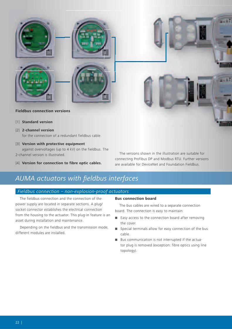
Fieldbus connection versions
[1] Standard version
[2] 2-channel version
for the connection of a redundant fieldbus cable.
[3] Version with protective equipment
against overvoltages (up to 4 kV) on the fieldbus. The
2-channel version is illustrated.
[4] Version for connection to fibre optic cables.
The versions shown in the illustration are suitable for
connecting Profibus DP and Modbus RTU. Further versions
are available for DeviceNet and Foundation Fieldbus.

| 23
[1][1]
[2][22]
[a][a]
[a][a]
[b][b]
Fieldbus connection – explosion-proof actuators
As for the non-explosion-proof actuators, the complete
electrical connection - both data cables and power supply
cables - is made in a separate plug-in connection.
If the actuator is the last device in the bus segment, the
fieldbus termination integrated in the AUMATIC has to be
wired accordingly.
For this type of connection, the bus communication is
maintained, even if the plug is disconnected
(exception: FO).
FO coupler
If the data exchange is performed via fibre optic cables,
an FO coupler is integrated in the connection housing for
connecting the fibre glass cables.
[1] Plug/socket connector with screw-type termi-
nals – standard (ordering code KP)
[2] Plug/socket connector with terminal blocks –
option (ordering code KES)
used with operating voltages exceeding 525 V and/
or, if many terminals are required, e.g. due to redundancy,
assignment of the sensor connections or connection of an
external 24 V DC supply
[3] Plug/socket connector with FO coupler –
option, not illustrated (ordering code KES)
for connecting fibre optic cables (Profibus DP or
Modbus RTU). Looks similar to [2]. FO coupler is installed
instead of terminals
[a] Screw-type terminals
[b] Terminal blocks

24 |
Bus
SIMA: Fieldbus master and actuators from a single source
From the perspective of the field devices, the SIMA
master station is used to set up an additional level below
the actual DCS. This is recommended if:
■ a protocol has to be converted, e.g. from Profibus DP
to Ethernet.
■ a physical conversion is required, e.g. from RS-485 to
RS-232.
■ a conversion from 1-channel to 2-channel operation
(redundancy) is required.
■ the process control system should not be burdened
with diagnostic data and actuator parameters.
SIMA simplifies the device integration of AUMA actua-
tors. SIMA uses open standardised fieldbus protocols
enabling the integration of field devices of other manufac-
turers.
SIMA’s advantages
■ Easy commisioning
Only the SIMA master station has to be integrated in
the host distributed control system as the only station.
■ Data logging
System data such as operating data or feedback signals
from the AUMA actuators can be stored in the master
station.
■ Windows user interface
Standardised operation using a worldwide renowned
operating concept
■ Expandable
Further AUMA actuators can be added with hardly any
effort.
■ Internet access
Online access via the World Wide Web by means of
standardised technologies
■ Logging of operation data
The SIMA operating data logging function enables the
collection of information on the operating time, the
number of starts, etc. of the slaves connected.
■ Local operation/monitoring
The SIMA can be monitored and controlled from dif-
ferent locations within the plant.
Configuration interface
As an industrial system, the SIMA master station comes
with ports for connecting screen, mouse and keyboard.
The SIMA software can be accessed via Windows user
interface. As an alternative, a laptop or computer can be
connected via Ethernet.

| 25
Control system
[1][1] [1][1]
[2][2][ ][2][ ]
[2][2][2]
[3][3][3][3]
[4][4][4] [4][4][4]
[1] SIMA master station
The SIMA is based on standardised industrial computer
components and has been expanded by the required field-
bus interfaces. The entire hardware is integrated in a solid
19" industrial housing with EMC protection. To increase
long-term availability, the whole system is passively cooled
and there are no rotating or moving parts. The SIMA is
available both with or without touchscreen.
[2] Communication
For the communication with field devices, SIMA sup-
ports the standardised fieldbus protocols such as Profibus
DP or Modbus RTU. The cable types specified in the field-
bus standards are used as transmission medium.
Up to 32 devices can be connected to a single bus
segment; when using repeaters, up to 247 devices are
possible.
Communication with the decentralised control system
is also performed according to above mentioned stand-
ards; in addition, Ethernet or customised RS-232 solutions
can also be used.
[3] Redundancy
SIMA supports various redundancy concepts. Both
redundancy to the AUMA field devices and/or to the DCS
and also SIMA master redundancy is possible. In case of
loss of communication or master failure, automatic
change-over to the redundant component will be perfor-
med.
[4] AUMA actuators
The SIMA is designed for controlling AUMA actuators.
Since the communication is performed according to stand-
ardised fieldbus protocols such as Profibus DP or Modbus
RTU, any field device conforming to these standards may
be integrated.

26 |
AUMA presales & after-sales
AUMA technical fieldbus support
Despite the standardisation, implementing, install-
ing and commissioning a fieldbus system is anything
but trivial. Should any mistakes by made at this level, the
problems caused by the delayed operation start and faults
outweigh the obvious advantages of fieldbus technology.
If the components involved are carefully selected at the
planning stage, this enables a smooth system start at a
later date.
Since the beginning of the 1990s, AUMA has been
engaged in the development of fieldbus technology.
AUMA engineers in Germany and in the AUMA subsidiar-
ies worldwide can rely on extensive experience – an asset
from which our customers can benefit when selecting the
suitable device configuration.
The crucial points for the configuration of the system
are settled in direct contact with the project engineer. This
includes for example transmission medium, redundancy
or the projected process control system. Only once these
questions have been answered, a detailed plant configura-
tion can be defined.
AUMA fieldbus service
AUMA after sales service
AUMA has set up a worldwide service network which
is unique in valve automation. AUMA service technicians
offer complete service on actuators and have a sound
knowledge of the surrounding infrastructure including
fieldbus systems.
AUMA commissioning service
AUMA service technicians will adapt the actuator ideally
to the chosen application. This includes setting the device
parameters such as tripping torques or type of seating, but
also configuring the bus address and the termination resis-
tors and checking the connection of the fieldbus cable.
AUMA fieldbus diagnostic service
AUMA service technicians do not just perfom diagnostic
checks on the actuators, they are also capable of verifying
the wiring and the data exchange quality.
AUMA service technicians are well-equipped with the
latest diagnostic devices and monitoring equipment for
the different fieldbus systems. Causes of faults can thereby
quickly be determined and eliminated.

| 27
Links & literature
Links
On the websites of the various development organisa-
tions and notified bodies, you can find comprehensive
information on the corresponding fieldbus system. Fur-
thermore, the device integrations of the registered field
devices, including AUMA actuators, are made available for
download. These files can also be downloaded from the
AUMA website www.auma.com.
■ Profibus DP: www.profibus.com/pb
■ Modbus RTU: www.modbus.org
■ DeviceNet: www.odva.org
■ Foundation Fieldbus: www.fieldbus.org
Literature
Profibus DP
■ Profibus DP, Grundlagen, Tips und Tricks für Anwender.
Manfred Popp: Hüthig Verlag, ISBN 3-7785-2676-6
■ The New Rapid Way to Profibus DP
Manfred Popp: can be obtained via www.profibus.com
■ Installation Guideline PROFIBUS-DP/FMS order no.
2.112, Profibus Nutzerorganisation,
■ Profibus Installation, Wiring and Commisioning Recom-
mendations and Guidelines,
Download www.profibus.com
Modbus
■ Modicon Protocol: Reference Guide PI-MBUS-300
■ Modbus Application Protocol Specification, Modbus
over serial line specification and implementation guide
DeviceNet
■ DeviceNet Specification Volume I, Rel. 2.0, Errata 5,
March 31, 2002
■ DeviceNet Specification Volume II, Rel. 2.0, Errata 5,
March 31, 2002
■ Controller Area Network Grundlagen, Protokolle,
Bausteine, Anwendungen, 3. aktualisierte Auflage,
Hanser Verlag, ISBN 3-446-21776-2
Foundation Fieldbus
■ Fieldbus FOUNDATION, (www.fieldbus.org):
AG-140 31.25 kbit/s Wiring and Installation Guide
AG-163 31.25 kbit/s Intrinsically Safe Systems Applica-
tion Guide
AG-165 Fieldbus Installation and Planning Guide
AG-181 System Engineering Guidelines
■ FD-043 Technical Overview
■ Foundation Fieldbus, A pocket guide –
Ian Verhappen, Augsto Pereira ISBN 1-55617-775-5
■ Fieldbuses for Process Control, Engineering, Operation
and Maintenance - Jonas Berge ISBN 1556177607

28 |
EU Directives
Declaration of Incorporation in compliance with the Machinery Directive and Declaration of Conformity according to the, ATEX, Low Voltage and EMC Directives
According to the Machinery Directive, AUMA actuators
and actuator controls are considered as partly completed
machinery. This means that a Declaration of Conformity
in accordance with this Directive will not be issued by
AUMA. AUMA’s Declaration of Incorporation confirms
that during the design stage of the devices, the funda-
mental safety requirements stipulated in the Machinery
Directive were applied.
AUMA actuators fulfil the requirements of the ATEX,
Low Voltage and EMC Directives. This has been proved in
extensive tests. Therefore, AUMA issues a Declaration of
Conformity.
The declarations of incorporation and conformity form
a joint certificate, also integrated within the operation
instructions.
According to the Low Voltage and EMC Directives, the
devices are labelled with the CE mark.
Certifi cates
Final inspection record
After assembly, all actuators are thoroughly tested
according to AUMA’s inspection specification and the
torque switches are calibrated. The procedure is recorded
on the final inspection record.
Certificates
To prove the suitability of the devices for special
applications, testing authorities perform type tests on
the devices. One example are the tests to prove electri-
cal safety for the North American market. If a device has
passed the test, this is recorded in a certificate. For all
devices mentioned in this brochure, the relevant certifi-
cates can be provided.
Where can I get the certificates?
All certificates and records are provided by AUMA on
request either as a hard or digital copy.
The documents can be downloaded from the AUMA
homepage, 24/24 hours; some of them are password
protected.
■ www.auma.com
AUMA devices have proven their compliance with
standards and their suitability for many applications by
going through numerous qualification procedures.
The resulting certificates provide you with the confi-
dence that a device which can be easily integrated into its
environment and will work without incidence over a long
time period.
Besides the certificates shown here, the devices are
awarded with more certificates.
SIL - Functional safety
AUMA has performed a risk analysis and a risk assess-
ment in compliance with EN 61508. Upon request, the
results can be supplied.

| 29
CERTIFICATE
The Certification Body of TÜV SÜD Management Service GmbH
certifies that
AUMA Riester GmbH & Co. KG
Aumastr.1, D-79379 Müllheim
has established and applies a Quality and Environmental Management System
for the following scope of application:
Research and development, manufacture, sales and service of electric actuators, integral controls and gearboxes
for valve automation as well as components for general actuation technology.
Performance of audits (Report No. 70009378) has furnished proof that the requirements under:
ISO 9001: 2008 ISO 14001: 2004
are fulfilled. The certificate is valid in combination with the main certificate until 2012-06-08
Certificate Registration No. 12 100/104 4269/01 TMS
Munich, 2009-06-25
QMS/EMS-TGA-ZM-07-92
Actuators must be reliable and dependable. They
determine the cycle of precisely defined work processes.
Reliability does not begin during commissioning. It begins
with a well thought out design and careful selection of
materials. This continues with reliable production using
state-of-the-art machine tools. This is done in clearly con-
trolled and supervised production steps whilst keeping in
mind the environment.
The importance of environmentally sound production is
reflected in our certifications according to ISO 9001 and
ISO 14001. However, quality management is no one-time
or static matter. It has to be proven day by day. Numer-
ous audits by our customers and independent institutes
confirm these high standards.
Quality is not just a matter of trust

30 |
AUMA worldwide
Europe
AUMA Riester GmbH & Co. KGWerk MüllheimDE-79373 Müllheim
Werk Ostfi ldern-NellingenDE-73747 Ostfi ldern
Service-Center KölnDE-50858 Köln
Service-Center MagdeburgDE-39167 Niederndodeleben
Service-Center BayernDE-85386 Eching
AUMA Armaturenantriebe GmbHAT-2512 Tribuswinkel
AUMA (Schweiz) AGCH-8965 Berikon
AUMA Servopohony spol. s.r.o.CZ-250 01 Brandýs n.L.-St.Boleslav
OY AUMATOR ABFI-02230 Espoo
AUMA France S.A.R.L.FR-95157 Taverny Cedex
AUMA ACTUATORS Ltd.GB- Clevedon North Somerset BS21 6QH
AUMA ITALIANA S.r.l. a socio unicoIT-20023 Cerro Maggiore (MI)
AUMA BENELUX B.V.NL-2314 XT Leiden
AUMA Polska Sp. z o.o.PL-41-310 Dabrowa Górnicza
OOO Priwody AUMARU-124365 Moscow a/ya 11
ERICHS ARMATUR ABSE-20039 Malmö
GRØNBECH & SØNNER A/SDK-2450 København SV
IBEROPLAN S.A.ES-28027 Madrid
D. G. Bellos & Co. O.E.GR-13671 Acharnai Athens
SIGURD SØRUM A. S.NO-1300 Sandvika
INDUSTRAPT-2710-297 Sintra
MEGA Endüstri Kontrol Sistemieri Tic. Ltd. Sti.TR-06810 Ankara
CTS Control Limited Liability CompanyUA-02099 Kiyiv
AfricaAUMA South Africa (Pty) Ltd.ZA-1560 Springs
A.T.E.C.EG- Cairo
Detailed information on AUMA products can be found on the Internet at: www.auma.com

| 31
AmericaAUMA Automação do brasil ltda.BR- Sao Paulo
AUMA ACTUATORS INC.US-PA 15317 Canonsburg
AUMA Chile Respresentative Offi ceCL-9500414 Buin
LOOP S. A.AR-C1140ABP Buenos Aires
TROY-ONTOR Inc.CA-L4N 8X1 Barrie Ontario
MAN Ferrostaal de Colombia Ltda.CO- Bogotá D.C.
PROCONTIC Procesos y Control AutomáticoEC- Quito
IESS de Mexico, S.A. de C.V.MX-C.P. 02900 Mexico D.F.
Corsusa International S.A.C.PE- Miralfl ores - Lima
PASSCO Inc.PR-00936-4153 San Juan
SuplibarcaVE- Maracaibo Estado, Zulia
AsiaAUMA Actuators (Tianjin) Co., Ltd.CN-300457 Tianjin
AUMA (INDIA) PRIVATE LIMITEDIN-560 058 Bangalore
AUMA JAPAN Co., Ltd.JP-210-0848 Kawasaki-ku, Kawasaki-shi Kanagawa
AUMA ACTUATORS (Singapore) Pte Ltd.SG-569551 Singapore
PERFECT CONTROLS Ltd.HK- Tsuen Wan, Kowloon
DW Controls Co., Ltd.KR-153-783 Seoul Korea
Petrogulf W.L.LQA- Doha
Sunny Valves and Intertrade Corp. Ltd.TH-10120 Yannawa Bangkok
Top Advance Enterprises Ltd.TW- Jhonghe City Taipei Hsien (235)
AustraliaBARRON GJM Pty. Ltd.AU-NSW 1570 Artarmon

[1] [2] [3]
[4] [5]
[6] [7]
[1] [3][2]
[5]
[8]
Certificate Registration No.12 100/104 4269
[1] Multi-turn actuatorsSA 07.2 – SA 16.2SA 25.1 – SA 48.1 Torques from 10 to 32 000 NmOutput speeds from 4 to 180 rpm
[2] Multi-turn actuators SA/SARwith controls AUMATICTorques from 10 to 1,000 NmOutput speeds from 4 to 180 rpm
[3] Linear actuators SA/LEcombination of multi-turn actuator SA andlinear thrust unit LEThrusts from 4 kN to 217 kNStrokes up to 500 mmLinear speedsfrom 20 to 360 mm/min
[4] Part-turn actuatorsSG 05.1 – SG 12.1Torques from 100 to 1,200 NmOperating times for 90° from 4 to 180 s
[5] Part-turn actuators SA/GSCombination of multi-turn actuator SA andpart-turn gearbox GSTorques up to 675,000 Nm
[6] Bevel gearboxesGK 10.2 – GK 40.2Torques up to 16,000 Nm
[7] Spur gearboxesGST 10.1 – GST 40.1Torques up to 16,000 Nm
[8] Lever gearboxesGF 50.3 – GF 250.3Torques up to 45,000 Nm
Subject to change without notice. The product features and technical data provided do not express or imply any warranty.Y004.112/002/en/1.10
AUMA Riester GmbH & Co. KG
P.O. Box 1362
79379 Müllheim, Germany
Tel +49 7631-809-0
Fax +49 7631-809-1250
For detailed information on AUMA products, please refer to the Internet: www.auma.com