electric drive technology at dspace -...
TRANSCRIPT

Electric Drive Technology at dSPACEDeveloping and Testing Electronic Control Units
www.dspace.com

Contents Electric Drive Technology 3
Developing with Rapid Control Prototyping 4
Use Cases 6
Success Stories 11
dSPACE Products
MicroAutoBox II 17
AC Motor Control Solution 19
RapidPro Hardware 22
DS1103 PPC Controller Board 23
DS5203 FPGA Board 26
Battery Cell Voltage Measurement and
Balancing 29
Testing with Hardware-in-the-Loop Simulation 30
Use Cases 32
dSPACE Products
EMH (Electric Motor HIL) Solution 40
DS2655 FPGA Base Module 45
Programmable Generic Interface (PGI1) 47
Electronic Load Modules 48
Battery Cell Voltage Emulation 52
ASM Electric Components Model 54
XSG Electric Component Library 56
XSG Utils Library 57
JMAG-RT Parameterization Support 58

32013
Electric Drive TechnologyDeveloping and Testing Electronic Control Units
Electric drives have been used increasingly over the past few
years. Not only in vehicles, but also in automation technolo-
gies and other applications. The reason: They have numer-
ous advantages and wide-ranging application potential in
many areas.
Application Areas of Electric Motors
In automotive applications, electric drives are being incor-
porated into numerous complex, basic, and safety-relevant
vehicle functions. Some examples of automotive applica-
tions are:
Electric steering systems
Powertrain actuators
Starter-generator systems
Electric vehicles
Mild/full-hybrid systems
Electric brake systems
Electric window lifters
Auxiliary aggregates: oil pumps, water pumps, etc.
Electric motors are also in widespread use in the capital
goods industry, medical engineering, and aerospace. Espe-
cially aerospace applications have high requirements regard-
ing safety and reliability.
Other applications include:
Wind energy converters
Electric trains
Printing machines
Roller mills for cold and warm roll forming
Zinc coating plants (headway and drive control)
Artificial respirators
Magnetic resonance tomography
Bipedal walking robots
Electric motors can be very small and fit almost anywhere.
They have very high dynamics and provide high torque at
lower rotational speed. Other advantages are improved
energy savings due to power-on-demand, better control-
lability, and easier maintenance.

42013
Developing with Rapid Control Prototyping
Advantages of Rapid Control Prototyping
To develop a new control strategy, you have to evaluate
different approaches and functions. You need to concentrate
completely on your function development and should not
have to worry about the performance of the prototyping
design iterations of the control algorithm on the real object.
RCP systems for electric motor control development need
to meet specifi c requirements with regard to:
Powerful system architecture
Flexible I/O interfaces
Dynamic power stages
An intuitive software environment
New controller functionDeveloped in
Simulink/Stateflow
Tests for: Electric motors Hybrid controllers EPS (electronic power steering) ...
Controller
Challenges of Developing Electric Motors
The trend towards mechatronic integration means that
electric motors are gaining popularity. However, their ad-
vantages are accompanied by a higher workload for inte-
grating the additional control algorithms into the respective
controller. The result is a more complex controller software,
which usually leads to increased development times. This
drawback can be countered by using model-based design
along with rapid control prototyping (RCP) to accelerate
hardware. Ideally, you can optimize your function designs
both on the test bench and in the actual vehicle or industrial
drive system until they meet the requirements – all without
having to do any programming.

52013
Rapid Control Prototyping
Easy Workfl ow
New functions are typically developed in MATLAB®/Simu-
link®/Statefl ow®. dSPACE Real-Time Interface (RTI) is the link
between this development software and the dSPACE hard-
ware. It automatically implements the MATLAB/Simulink/
Statefl ow model on the dSPACE MicroAutoBox, the modular
hardware installed in the AutoBox, or the stationary dSPACE
Expansion Box. If function modifi cations are necessary dur-
ing the tests, you can simply correct a function in Simulink
and fl ash it to the hardware again. The dSPACE prototyping
system substitutes for any controller and its connections to
the vehicle or the controlled system during the develop-
ment process.
Solutions for Electric Drive Applications
dSPACE offers specialized products for the highly dynamic
requirements of electric drives:
The AC Motor Control Solution is installed in
the AutoBox to control diverse AC motors.
The AC Motor Control Solution upgrades
MicroAutoBox II to a compact, fl exible development
system for electric motor control applications.
The MicroAutoBox II acts as the central controller.
Its high performance enables unrestricted testing of
new functions.
The RapidPro system can be used to extend the
AutoBox or MicroAutoBox II. It offers specialized half-
bridge and full-bridge modules which can deliver
peak currents of up to 60 A for applications with
electric drives and valves. The RapidPro module for the
universal control of brushless electric motors provides
special support for tasks such as electrifying auxiliary
aggregates.
The DS1103 PPC Controller Board is an all-rounder
for rapid control prototyping that provides a real-time
processor and comprehensive I/O.
For further product information, please see:
MicroAutoBox II, page 17
RapidPro, page 22
DS1103 PPC Controller Board, page 23
AC Motor Control Solution, page 19
DS5203 FPGA Board, page 26
Design, simulation and analysison a PC
Implementationon real-time hardware
Monitoring, tuning
I/O connection via library
Real-time simulation and verification in a real environment

62013
Rapid Control Prototyping / Use Cases
EngineECU
E-MotorECU
ElectricMotor
TransmissionECU
BatteryManagement
System
High VoltageBattery
Hybrid Powertrain
ECU
Trans-mission
CombustionEngine
Powertrain CAN
Hybrid CAN
Inverter
to Drive Shaft(Vehicle
Dynamics)
ControlDesk® Next Generation
RTI
Use Cases
Task
The main task in electric or hybrid electric powertrain devel-
opment is to design the overall control strategy. The control
functions are spread over a distributed network of electronic
control units. An additional task is to integrate the control
strategy into these distributed ECU networks.
Challenge
To develop the optimal ECU algorithms for electric motors,
you need to test various different control strategies. You
therefore need a development system that acts as a substi-
tute for the future central hybrid controller. The prototyping
system has to offer various interfaces and should be usable
in-vehicle.
The dSPACE MicroAutoBox II
acts as the central hybrid
ECU during the development
of new functions.
Developing Control Functions in Electric or Hybrid Electric Vehicles
Solution
During function prototyping, a dSPACE MicroAutoBox II
takes the place of the central hybrid controller. It offers
comprehensive bus interfaces and, with its compact and
robust design, it can be used in-vehicle.
The new functions developed with Simulink® are imple-
mented on the MicroAutoBox II with dSPACE Real-Time
Interface (RTI).

72013
Rapid Control Prototyping / Use Cases
Task
One reason for the combustion engine’s great success in
the 20th century is gasoline’s high energy density. While
one liter of gasoline can run for many kilometers, a modern
battery of the same mass or volume takes an electric vehicle
only a fraction of the distance. As this comparison clearly
shows, developing powerful, high-density batteries with a
maximum realizable capacity is key to the breakthrough of
electrical vehicles.
Challenge
Li-ion batteries have to be constantly monitored and con-
trolled because the usable voltage range of a Li-ion cell is
limited to several 100 mV. The further the voltage moves
out of this ideal range, the more the life span of the cell is
impaired. In extreme cases, the cell can even be
destroyed. Instances of battery fi res in telephones, laptops,
and last but by no means least, in planes, emphasize just
how important it is to monitor the battery state. To maximize
the battery´s overall capacity it is necessary to keep all cells
on the same level of charge.
Solution
To benefi t fully from the high energy density of Li-ion bat-
teries, the state of charge of the individual cells must be
monitored precisely. dSPACE has developed a RCP bat-
tery management system (p. 29) that performs this task
throughout the development process, from the fi rst model
to in-vehicle testing. Its main focus is on measuring and
Controlling Li-ion Cell Voltages During Prototyping
The modular structure of the dSPACE battery management system
allows tailor-made confi gurations of up to around 200 cells and can
also be installed directly in a vehicle.
Sensor Board
Board with balancing resistances
dSPACE PGI1
Ethernet
Ground
RF
Isolationwatchdog
Cut-off device
Electrical isolation
Enclosure Isolation fault
Battery
dSPACEsystem platform
The isolation concept of the dSPACE battery
management system makes it safe to use high
battery voltages.
controlling Li-ion batteries. The system is modular and can
be assembled to create confi gurations of between 6 and
approx. 200 cells. It can also be installed directly in a vehicle.
The BMS modules are connected via Ethernet with a dSPACE
prototyping system such as MicroAutoBox II.

82013
Rapid Control Prototyping / Use Cases
Robotics
Solution
The real-time system picks up the robot‘s six incremental
encoder signals to determine the current robot position.
Then this data is compared with the reference values.
Calculating a robotics control algorithm on a DS1103 PPC Controller Board.
Task
Rapid prototyping for robotic applications requires flexible
and fast interfaces, especially fast encoder interfaces that
are easy to access from the real-time Simulink model.
Challenge
The functions of the robotic position controller have to
be performed. In the example below, the controller board
replaces the position controller. The prototyping hardware
should also allow easy parameter modification for convenient
design optimization.
Further Processing Potential
All reference values are calculated in real time, even
for inverse kinematics with highly nonlinear functions.
External sensors such as axis-force momentum sensors can
be included. Trajectory planning and running advanced
algorithms for collision avoidance are also very convenient
with the DS1103 PPC Controller Board.
Afterwards, the DS1103 calculates the control algorithm and
sends the controller output – for example, data on positions
and velocities – back to the robot.

92013
Rapid Control Prototyping / Use Cases
In-Vehicle Prototyping
Solution
dSPACE offers a fl exible development environment for
in-vehicle prototyping of EVs and HEVs. The MicroAutoBox
provides convenient support of common bus interfaces
(CAN, LIN, FlexRay) for high connectivity. You can also use
the PGI1 (p. 47) with the MicroAutoBox to interface (via
Task
The task is to develop and verify control strategies and
distributed ECU functions in an electric vehicle (EV) or hybrid
electric vehicle (HEV) "on the road".
Challenge
To develop and verify algorithms for an EV/HEV ECU net-
work, you need a fl exible and in-vehicle capable develop-
ment system. Universal I/O interfaces, support for common
bus systems, and the ability to fl exibly hook up the electric
motor power stages are also necessary.
the TwinSync protocol) to various LTI power stages such as
the LTI ServoOne. This combination provides high fl exibility
with regard to the power stages, as you are able to connect
various electric motors with different power ranges exactly
as required.
MicroAutoBox
CAN
LVDS Link
LTi ServoOne
HV Battery
PGI1

102013
Rapid Control Prototyping / Use Cases
Control signals
RTI Blockset
PHS Bus
DS1005/DS1006
DS5202
EV1048
Motor
RapidPro Power Unit
Current signals
Resolver, SSI,
EnDat
Hall / Enco
der
Piggyback module used inside MicroAutoBox II
or
Solution
AC Motor Control Solution
The ACMC Solution, based on the MicroAutoBox or
the DS5202 FPGA Base Board mounted in an AutoBox,
is ideal for fast current/voltage measurement, connecting
diverse position encoders, and controlling AC motors.
The MicroAutoBox and the AutoBox can be installed
in-vehicle and connected to the electric motor. If installed
in a dSPACE Expansion Box, the ACMC Solution can also
control an industrial electric drive application.
The ACMC solution offers the I/O interfaces required for devel oping control strategies for various AC motors such as BLDC motors.
Developing Electric Motor Control Algorithms
Task
The task is to develop control functions for all types of
electric motors:
Asynchronous motors
Brushless DC (BLDC) motors
Permanent magnet synchronous motors (PMSM)
Challenge
Fast current and voltage measurements are required and
diverse position encoders have to be connected.
You can use the AC Motor Control Solution together with
the dSPACE RapidPro system to control PMSM and BLDC
motors.
Various piggyback modules can be plugged onto the DS5202
to provide specialized, comprehensive I/O functionality, with
the control algorithms running on a DS1005 or DS1006
processor board.

112013
Success StoriesRapid Control Prototyping /
E-Motion: Motion Control Algorithms for Electric Vehicles
Research Focus at Fujimoto Research Laboratory
The Fujimoto Research Laboratory at Yokohama National
University in Japan investigates electric vehicles, focus-
ing particularly on methods of electric drive technology.
The laboratory is working on a type of drive known as an
in-wheel motor, and is also studying the safety aspects of
electric vehicles on slippery road surfaces. Research is being
conducted on attitude control methods that employ yaw
rate control, using this yaw moment to prevent spinning
and drifting when turning.
Development Objective: A Yaw-Stable Vehicle
An electric motor goes straight from zero to its maximum
torque. Thus, uncontrolled torque requests can result in
immediate loss of static friction, which results in vehicle
oversteer during extreme cornering. To detect the beginnings
of oversteer, the vehicle’s yaw rate has to be determined.
The yaw rate is the angular velocity with which a vehicle
rotates around its vertical axis. If external effects push a
yaw-stable vehicle off course, in the ideal case it returns
to a straight path without the driver having to steer.
Test Drive with dSPACE AutoBox
To test the control algorithms in prac tical test drives, the FPEV
2-Kanon test vehicle was equipped with a dSPACE AutoBox
containing a DS1103 PPC Controller Board that was respon-
sible for computing the algorithms. A control system mod-
eled with MATLAB®/Simulink® was loaded to the AutoBox.
The AutoBox drives the electric motors via converters. The
angular velocity, the torque, the acceleration and the yaw
rate are available as analog signals.
Effectiveness of the dSPACE
AutoBox
To make full use of the advantages of
electric motors, the control algorithms
have to be calculated extremely fast.
The short sample time of the DS1103
PPC Controller Boards and its low
latencies during I/O access meant that
the algorithms could be executed in
real time. Since the hardware has such
extremely fast response times, the
algorithms behaved as expected.
ax,ay
f
150V
T*
,Treal
300V
ControllerAutoBoxDS1103( )
*
r*
Acceleration sensor
Yaw-rate sensor
Steering angle sensor
Li-ionbattery15Vx10
Chopper
RInverter
LInverter
RMotor
LMotor
MotorforSBW
MotorforSBW
Confi guration of the vehicle control system.
Success Stories

122013
Success StoriesRapid Control Prototyping /
Purely Regenerative Energy Supply
An autonomous, CO2-neutral power supply based on
regenerative energies for remote areas – islands or villages –
that are far away from the main power grid: That’s what
Younicous is planning and developing. The first project is
for the island of Graciosa in the Azores, where 70-90%
of the required energy could come from the sun and the
wind, and the remaining 10-30% could be generated from
locally produced biofuels. A 3-megawatt sodium sulfur
battery as electricity storage to compensate for large supply
fluctuations, and the island will be completely independent
of fossil fuels.
Developing the Converter Control
The battery converter control has two main components:
a real-time controller and a communication system.
To find the optimum control for the converter, Younicos
uses rapid prototying to test different voltage and frequency
control algorithms that were designed in MATLAB®/Simu-
link®. For the actual tests, the AC Motor Control Solution
from dSPACE was used. This consists of a DS1005 Proces-
sor Board and DS5202 FPGA Base Board with a piggyback
module. The algorithms are implemented on the DS1005 by
means of the dSPACE Real-Time Inter face (RTI), and then
executed on the board. The DS5202 provides the neces-
sary I/O connection between the processor board and the
converter. If any changes are made to an algorithm, they
can quickly be transferred from MATLAB/Simulink to the
DS1005 by using RTI.
Simulating Consumption, Wind, and Sun
For simulating wind turbines and solar power plants
Younicos implemented and executed their own simulation
models on several dSPACE DS1005 PPC Boards. Real wind
and sun data measured on the island of La Graciosa provides
the input parameters for ascertaining the currently avail-
able power. This available power is then compared with a
consumption profile that represents the island population’s
energy requirements throughout the day. Converters then
perform energy distribution. Each battery is coupled to
the simulated supply grid via a converter. The load on the
grid is represented by another converter that runs through
a scaled load profile of the island.
This solar power system feeds an autonomous charging station
for electric vehicles.
Younicos: New Energy
Carrying out the Project
In August 2012, Younicos and the local power supplier
signed agreements on power input to the electricity grid
and on the price of the electricity – the commercial base of
the project. The construction of the photovoltaic plant, wind
park and battery storage is expected to be completed at the
end of 2014, when the entire system will go into operation.

132013
Success StoriesRapid Control Prototyping /
MAGNA STEYR and its cooperation partners integrated
new hybrid components in a vehicle and implemented a
control system using a dSPACE prototyping system (Micro-
AutoBox plus RapidPro). The hybrid demo vehicle HySUV
(Mercedes M-class) with a dSPACE prototyping system as
the central drivetrain control has made the hybrid drive a
reality. MAGNA STEYR and its partners use the demo vehicle
as a platform for further optimization of driving behavior,
consumption, and emissions.
Drive Systems of the Future
MAGNA STEYR worked with MAGNA POWERTRAIN and
Siemens VDO to develop modular hybrid drive systems,
taking into account the research fi ndings from K-net KFZ,
the competence network for “Vehicle Drives of the Fu-
ture”. With the support of the OEMs, hybrid components
developed by MAGNA are integrated in the drivetrains of
prototype vehicles to investigate the optimization potential
of the consumption, dynamics, and emissions. The control
system and the cross-linking of new components in the drive-
train are implemented with the dSPACE prototyping system
(MicroAutoBox plus RapidPro) on the basis of a central hybrid
drive strategy. MAGNA STEYR has put this into operation in
the hybrid demo vehicle HySUV. The automatic transmission
and transfer case of a Mercedes ML350 were replaced by
an automated manual transmission and MAGNA’s E4WD
module consisting of 2 electric drives and clutches. A full
hybrid drivetrain with electrical all-wheel drive was imple-
mented in this way. A lithium-ion battery system, developed
by MAGNA STEYR, provides energy storage.
Prototyping Hardware and Function Development
The control software comprises the functions and inter-
faces of the entire torque path in the drivetrain. The ob-
jective was to control all the components of the hybrid
drivetrain with just one prototyping system. In addition to
their standard software development platform MicroAuto-
Box, MAGNA STEYR decided to use the RapidPro system to
effi ciently realize the broad range of signal conditioning
and power stages. Its fl exibility provided by software- and
hardware-confi gurable signal I/O proved to be an advantage,
particularly in early phases of prototype development, when
the sensor and actuator systems are not yet completely
defi ned. After the function software had been successfully
implemented and tested, MAGNA STEYR entered the test
drive phase, with the objective of further optimization.
System architecture:
The dSPACE proto-
typing system net -
worked in the
vehicle.
MAGNA STEYR: Hybrid Drive
E4WD
ESP
HMIAMT
Hardware connections
Bus connections
Measurement CAN
LVDS
Engine CAN
Hybrid CAN
High-voltage component
12-V component
Converters 1/2
Batterymanagement
system
High-voltagebatterysystem
Electricalmachines 1/2
Gateway
GatewayECU
Combustionengine
Air conditioning
Drivetrain CAN
dSPACE RapidPro
Actuator driver
Sensor I/OHardware
diagnostics
Air conditioningcompressor
Coolingcircuits 1-3
dSPACE MicroAutoBox
FunctionSystem
managerDiagnosticsCAN I/O

142013
Success StoriesRapid Control Prototyping /
As part of this competition, Ohio State University (OSU)
engineering students developed an HEV that is powered
by a combination of a turbocharged diesel engine, a high-
voltage, belted starter-alternator (BSA) and an AC induction
type traction electric machine. In this confi guration, the
rear and front drive systems are coupled through-the-road.
Control Implementation Using the MicroAutoBox
Prior to the actual implementation, OSU tested the per-
formance of its control strategy using custom-designed
vehicle simulation tools developed in the MATLAB®/Simu-
link® environment. After initial testing, the control strat-
egy was implemented on the MicroAutoBox system via
Ohio State University: Control of a Power-Split Hybrid-Electric SUV
The MicroAutoBox interfaces with the powertrain control modules via dual CAN buses and several I/Os.
Auxiliary controller
Exhaust systemCAN A
Driver
Rear electric motor
GM LANData
acquisition
Belted starter alternator
High-voltage battery pack
Engine & transmission
CAN B
dSPACE’s Real-Time Interface and the RTI CAN Blockset.
MicroAutoBox is the primary vehicle control unit to perform
fundamental hybrid powertrain operations such as energy
optimization, battery charge control, engine start-stop,
drivability control, electric traction control, and regenerative
braking. In the student-designed vehicle, the MicroAutoBox
communicates with several control modules through dual
CAN buses. The versatile I/O interface simplifi ed the inte-
gration of several analog and digital I/Os into the control-
ler for the added hybrid components. The fast numerical
processor featured by the MicroAutoBox made it possible
to implement computationally burdensome algorithms
onboard the vehicle.

152013
Success StoriesRapid Control Prototyping /
Deutz: Developing Hybrid Drives for Mobile Machines
Wheel Loader with Hybrid Drive
In a joint project with wheel loader specialist Atlas Weyhau-
sen, Deutz used dSPACE tools to develop what is called a
“mild” hybrid system for their AR-65 Super wheel loader.
“Mild” means that the electric motor is rigidly coupled to the
diesel engine and supports frequent braking and accelera-
tion. The following dSPACE tools were used to develop the
software functions for the hybrid system’s ECU:
MicroAutoBox (as the hybrid system ECU)
Real-Time Interface (for setting up the I/O interfaces
for the MicroAutoBox)
RTI CAN MultiMessage Blockset (for setting up CAN com-
munication)
ControlDesk® (for calibrating the hybrid functions)
By using RTI and the RTI CAN MultiMessage Blockset, Deutz
was able to implement fully functioning system software
on the MicroAutoBox in only 3 months. The RTI CAN Multi-
Message Blockset proved to be a very easy-to-use tool, and
CAN. Because the system software was programmed
directly in Simulink, it was possible to try out the software
functions immediately on a plant model (MIL) contain-
ing the engine, electric machine, inverter, battery, work
hydraulics and traction hydraulics. Deutz was therefore
able to test the software functions long before the fi rst
prototype components became available. This was abso-
lutely essential in view of the very short development time
assigned to this project.
Using the pretested software functions and the inputs and
outputs confi gured with RTI (digital, analog, PWM, CAN),
Deutz produced a software version that would run on the
MicroAutoBox and tested it on the test bench. Functions
such as start/stop were tested and calibrated with
ControlDesk.
Finally, Deutz put the wheel loader into operation with the
MicroAutoBox as a superordinate hybrid system ECU and
implemented the functions for boosting power and raising/
shifting the load point.
Schematic of the mild
hybrid system in the wheel
loader. The MicroAutoBox
is used as a superordinate
hybrid system ECU.
its support for linking
CAN confi guration fi les
(DBC fi les) enabled us
to set up the CAN com-
mu nication very quickly.
Three CAN channels
were set up in the wheel
loader: engine CAN,
hybrid CAN, and vehicle

162013
Success StoriesRapid Control Prototyping /
Additional Information
You can download success stories, articles and product
information on drive applications at www.dspace.com under
"Downloads".
Title Author Published at
Implementing Electromobile Ideas Holger Ross (dSPACE GmbH) Elektronik Automotive, Apr 2011
When Processor and FPGA Work Together Frank Mertens (dSPACE GmbH), Thomas Sander
(dSPACE GmbH)
Elektronik Automotive, May 2011
Get Your Ideas on Track Frank Mertens (dSPACE GmbH) Automobil Elektronik, Oct 2010
Intelligent I/O up Close Jürgen Klahold (dSPACE GmbH) Offprint translation from
"Hanser Automotiv", Nov 2009
All Inclusive/Off-the-Shelf Frank Mertens (dSPACE GmbH), Holger Ross
(dSPACE GmbH)
Offprint translation from
"Elektronik automotive", Oct 2009
Flexibility Can Be So Compact Frank Mertens (dSPACE GmbH), Holger Ross
(dSPACE GmbH)
Offprint translation from
"AutomobilElektronik", Oct 2008
Available Publications (Partial List)

172013
Rapid Control Prototyping / Products
MicroAutoBox® II
Compact prototyping unit for electric motor controls
Application Areas
MicroAutoBox is a real-time system for performing fast
function prototyping in fullpass and bypass scenarios.
It operates without user intervention, just like an ECU.
Key Benefi ts
The special strength of the MicroAutoBox hardware is its
unique combination of high performance, comprehen-
sive auto motive I/O, and an extremely compact and robust
design – all for a favorable price. This lets you equip sev-
eral vehicles or a whole test fl eet to check the reliabili-
ty of your control functions. In addition to the standard
I/O, MicroAutoBox offers variants with FPGA functionality
for application-specifi c I/O extensions and for user-program-
mable FPGA applications. Moreover, there are MicroAutoBox
variants with inter faces for all major auto motive bus systems:
CAN, LIN, K/L line, FlexRay, and Ethernet.
Comprehensive I/O including CAN, LIN, K/L line,
FlexRay, Ethernet, and LVDS/bypass interfaces
Robust and compact design ideal for in-vehicle use
IBM PowerPC running at 900 MHz
Variant with Simulink®-programmable FPGA
AC Motor Control Solution (p. 19)
NEW: Multistage watchdog mechanism
dSPACE Products
16 MBlocal RAM
EthernetI/O
interface
Con-nector(LEMO)
Con-nector(LEMO)
Con-nector(LEMO)
Con-nector(LEMO)
Con-nector(LEMO)
ECU interface
ECU interface
USB
Watchdog
Clock/calendar
16 MBflash
(non-volatile)
6 MBcommunic.memory
Ethernethost
interface
64-Bit G
lobal Bus
Performance timer
IBM PPC750 GL
Signal Conditioning
Signal Generation/Measurement
I/O Connector
IP module slot(e.g., for FlexRay)
IP module slot(e.g., for FlexRay)
FPGAextension slot
ProgrammableFPGA
Signalconditioning& protection
Signalconditioning& protection
Signal driver& protection
Optional signal conditioning on DS1552
or ACMC SolutionAdd-On Modules1)
CAN/LIN/serialmodule
CAN/LIN/serialmodule
Signal Conditioning
Signal Generation/Measurement
I/O Connector
4-channel12-bit DAC
Digital I/O(FPGA-based)
16-channel16-bit ADC
PhysicalCAN/serial
PhysicalCAN/serial
Local B
us/Interm
odule Bus
MicroAutoBox II
1401/1511/1512

182013
Rapid Control Prototyping / Products
Technical Details
Parameter Specification
MicroAutoBox II 1401/1511 1401/1511/1512
Processor IBM PPC 750GL, 900 MHz (incl. 1 MB level 2 cache)
Memory 16 MB main memory
6 MB memory exclusively for communication between MicroAutoBox and PC/notebook
16 MB nonvolatile flash memory containing code section and flight recorder data
Clock/calendar function for time-stamping flight recorder data
Boot time Depending on flash application size. Measurement examples: 1 MB application: 160 ms; 3 MB application: 340 ms
Inter-
faces
Host interface 100/1000 Mbit/s Ethernet connection (TCP/IP). Fully compatible with standard network infrastructure. LEMO connector.
Optional XCP on Ethernet interface to support third-party calibration and measurement tools
Real-time I/O
interface
100/1000 Mbit/s Ethernet connection (UDP/IP). RTI Ethernet (UDP) Blockset (optional) for read/write access.
LEMO connector.
USB Interface USB 2.0 interface for long-term data acquisition with USB mass storage devices. LEMO connector.
CAN interface 2 dual CAN interfaces; 4 CAN channels in total
Serial interface (based
on CAN processor)
2 x RS232 interface
2 x serial interface usable as K/L line or LIN interface
Dual-port memory
inter face (ECU interface)
2 x dual-port memory interface,
16 K x 16-bit DPRAM
FlexRay interface – 2 slots1) for FlexRay modules (i.e. 4 FlexRay channels)
Programmable FPGA – Xilinx® Spartan®-6 LX1502)
Analog
input
Resolution 16 16-bit channels 16 16-bit channels (additional channels with DS1552)
Sampling 16 parallel channels with 1 MSPS conversion rate
Input voltage range 0 ... 5 V
Analog
output
Resolution 4 12-bit channels 4 12-bit channels (additional channels with DS1552)
Output voltage range 0 ... 4.5 V 0 ... 4.5 V
Output current 5 mA max. sink/source current
Digital
I/O
General
FPGA-based digital I/O
RTI software support for bit I/O, frequency, and PWM generation/measurements
Bit I/O
40 inputs
40 outputs, 5 mA output current
40 inputs (additional channels with DS1552)
40 outputs, 5 mA output current (additional channels with
DS1552)
Input / output logic levels: 5 V or levels up to 40 V (depending on VDrive), selectable
PWM generation/
measurement
All channels fully configurable as frequency or PWM inputs/outputs
PWM frequency 0.0003 Hz ... 150 KHz, duty cycle 0 ... 100%, up to 21-bit resolution
Signal conditioning Signal conditioning for automotive signal levels, no power driver included
Overvoltage protection
Overcurrent and short circuit protection
Physical connections ZIF connector for I/O signals, mechanically secured, Sub-D connector for power supply
LEMO connectors for 2 ECU interfaces, Ethernet I/O interface, USB interface, and Ethernet host interface
Ethernet I/O interface for notebook/PC for program load, experiment configuration, signal monitoring and flight recorder
read-out
Integrated Ethernet switch
Physical
characteristics
Enclosure
material
Cast aluminum box
Enclosure size Approx. 200 x 225 x 50 mm (7.9 x 8.9 x 2.0 in) Approx. 200 x 225 x 95 mm (7.9 x 8.9 x 3.8 in)
Temperature Operating (case) temperature: -40 ... +85 °C (-40 ... +185 °F)
Storage temperature: -55 ... +125 °C (-67 ... +257 °F)
Power supply 6 ... 40 V input power supply, protected against overvoltage, and reverse polarity
Power
consumption
Max. 25 W Max. 50 W
1) IP module slot. Can also be used for other IP modules such as an ARINC interface module (via dSPACE Engineering Services).2) User-programmable via RTI FPGA Programming Blockset. Using the RTI FPGA Programming Blockset requires additional software.

192013
Rapid Control Prototyping / Products
Fast current/voltage measurements
Control of AC motors, e.g., asynchronous motors,
brushless DC motors (BLDCs) and permanent magnet
synchronous motors (PMSMs)
Suitable PWM generation for electric drives
Connection of diverse position encoders
RTI Blockset for MATLAB®/Simulink®
AC Motor Control SolutionControl of diverse AC motors
Purpose
The AC Motor Control Solution is based on the DS5202
FPGA Base Board and on the MicroAutoBox with DS1512
I/O Board.
These are specially designed for fast current / voltage mea-
surements, connecting diverse position encoders and control
ling AC motors such as ASMs, BLDCs and PMSMs. Rapid
prototyping of AC motors requires fast I/O, which is fullfi lled
by using an FPGA Base Board and the appropriate piggyback
module, with the control algorithms running on the main
processor. The interface between the user's control model
and the AC Motor Control hardware is realized by the AC
Motor Control Solution RTI Blockset.
Use Cases
Typical use cases for the AC Motor Control Solution are
highly dynamic control systems for different types of AC
motors.
Some scenarios are:
Field-oriented control of PMSMs or ASMs
Controlling BLDCs
Prototyping new methods for sensorless control
Using RapidPro Power Unit with suitable modules or
customer-specifi c power converters
To use the AC Motor Control Solution in a vehicle, you can
install it in the dSPACE AutoBox or use the MicroAutoBox
variant. For stationary use, it can be installed in an Expan-
sion Box.
Applications
Measurements (of phase currents and/or voltages,
and DC link currents or voltages) and ADC starts can
be synchronized to PWM signals
Position and speed measurements using typical
sensors such as Hall sensors or incremental encoders,
resolvers, or typical single/multiturn encoders with
serial interfaces (EnDat or SSI)
Generation of gate driver signals (center-aligned
3/6 PWMs for sinusoidal commutation or PWM signals
for block commutation or advanced customer-specifi c
PWM patterns)
Synchronization of ADC measurement with center-
aligned PWM signals (regular sampling)
Model synchronization by interrupt generation at the
center position of the PWM or at user-defi ned motor
angles
Trigger signal to external devices at the center position
of the PWM

202013
Rapid Control Prototyping / Products
Control signals
RTI Blockset
PHS Bus
DS1005/DS1006
DS5202
EV1048
Motor
RapidPro Power Unit
Current signals
Resolver, SSI,
EnDat
Hall / Encoder
Piggyback module used inside MicroAutoBox II
or

212013
Rapid Control Prototyping / Products
AC Motor Control Solution for MicroAutoBox II
Electric Drives Control
The AC Motor Control (ACMC) Solution upgrades the
MicroAutoBox II to a compact, flexible development system
for electric motor control applications. The ACMC solution
consists of an add-on hardware module which provides the
I/O interfaces for diverse AC motors and utilizes the new
FPGA functionality of the MABX II 1401/1511/1512. It also
comes with a dedicated RTI Blockset as the interface to the
user´s control model.
This includes:
Control of AC motors, e.g., asynchronous motors (ASMs),
brushless DC motors (BLDCs) and permanent magnet
synchronous motors (PMSMs)
Flexible I/O interfaces for diverse position sensors such
as hall sensors, encoders and resolvers
Suitable PWM generation for electric drives
Dedicated RTI Blockset for MATLAB®/Simulink®
Available with MicroAutoBox variant 1401/1511/1512
Technical Data (AC Motor Control Solution for MicroAutoBox II)
Scope of Delivery (AC Motor Control Solution
for MicroAutoBox II)
I/O piggyback module for AC motor control applications
FPGA firmware for AC motor control applications
Simulink interface for AC motor control applications
Parameter Specification
Digital input 8 channels, 0 ... 5 V, differential or single-ended, configurable by software.
Example: 3 x single-ended for Hall sensor, 3 x differential for incremental encoder, 2 x single-ended for bit in,
frequency and duty cycle measurement
Digital output 24 channels, 0 ... 5 V, single-ended to generate gate driver signals, PWM synchronization signals, bit out
Gate driver frequency 10 Hz ... 1 MHz
ADC 8 channels, software-configurable inpult voltage range (±5 V, ±15 V, ±30 V), differential, 10 MSPS
DAC 2 channels, -10 ... 10 V (single-ended) or -20 ... 20 V (differential, reference to GND)
Resolver interface Max. position resolution 16 bit (depending on motor velocity). Generation of excitation signal (3,7,10 Vrms;
excitation frequency from 2 ... 20 kHz within 250 Hz steps (software-configurable)
RS422/RS485 SSI oder EnDat for connection of single/multi-turn encoder
4 RS485 transceivers (Endat or SSI Interface)
Power Supply for sensors 12 V: max. 50 mA
5 V: max. 50 mA (use the MicroAutoBox II VSENS-PIN for currents up to 250 mA)

222013
Rapid Control Prototyping / Products
Power Stage
Module (PS Module) Description
PS-HSD 6/1 6-channel high-side driver module
Requires 1 slot in a RapidPro unit
4 output channels with up to 5 A, clamping voltage 48 V
2 output channels with up to 1 A, clamping voltage 63 V
Max. supply voltage: 36 V continuous, 40 V peak
Switching time: <30 µs
Load failure diagnosis
Current measurement with hardware-adjustable low-pass fi lter (1st order) on channel 1 and 2
Overload protection, overtemperature protection, short-circuit protection to ground, VBAT and across the load, active output clamping
Integrated on carrier board: load dump protection up to +100 V (only valid for internal voltage supply of the module), reverse
voltage protection up to -100 V
PS-HCFBD 1/2 1-channel high-current full bridge driver module
Requires 3 slots in a RapidPro unit
Up to 60 A DC peak current (1 s), 42 A rms continuous (T ambient = 25 °C, fi lter frequency 1 kHz, corresponding duty cycle)
Up to 60 A DC peak current (1 s), 29 A rms continuous (depends on ambient temperature)
Max. supply voltage: <20 V continuous
Current measurement with hardware-adjustable low-pass fi lter (1st order)
Internal free-wheeling diodes
Protection against: short circuit, overtemperature, and overvoltage
Load failure diagnostics
PS-HCHBD 2/2 2-channel, high-current, half-bridge driver module
Requires 3 slots in a RapidPro unit
Each channel up to 30 A peak current (1 s), 25 A rms continuous (depends on ambient temperature)
Parallel mode possible (30 A DC peak per channel, 19 A rms continuous per channel)
Usable as half-bridge or low-side or high-side driver output
Max. supply voltage: <20 V continuous
Current measurement with hardware-adjustable low-pass fi lter (1st order) for each channel
Internal free-wheeling diodes
Protection against short circuit, overtemperature, and overvoltage
Load failure diagnostics
RapidPro Hardware
Power Stages for Electric Drive Applications
Especially in the rapid prototyping phase, versatile power
stages are required for driving different electric motors. Ide-
ally, only a minimum of hardware development, or none at
all, should be necessary to connect electric motors to the
prototyping system. In reality, the design and implementa-
tion of such circuits can be an expensive and time-consuming
task. Confi guring the power stage hardware later on during
the course of a project also usually involves a lot of work. The
fl exibility and intelligent assistance provided by the RapidPro
hardware and the corresponding software from dSPACE will
help you achieve challenging tasks for power stages with
high effi ciency.
Scalable, modular, and confi gurable system architecture
Compact and robust enclosure
For in-vehicle, laboratory, and test bench use
Comprehensive software support
Application-specifi c confi gurations for common
application areas
RapidPro Modul Examples1)
222013
Electric drive power stages
1) Further signal conditioning and power stage modules available.

232013
Rapid Control Prototyping / Products
DS1103 PPC Controller Board
Single-board system with real-time processor
and comprehensive I/O
CAN interface and serial interfaces ideally suited
to automotive applications
High I/O speed and accuracy
PLL-driven UART for accurate baud rate selection
Powerful controller board for rapid control prototyping
Application Areas
The DS1103 controller board is designed to meet the require-
ments of modern rapid control proto typing and is highly
suitable for applications such as:
Automotive controllers
Electric motor control
Robotics
Positioning systems and stepper motors
Active vibration control
An integrated Infi neon CAN microcontroller makes the
board an attractive tool for automotive and automation
applications.
Key Benefi ts
The DS1103 is an all-rounder in rapid control prototyp-
ing. You can mount the board in a dSPACE Expansion Box
or dSPACE AutoBox to test your control functions in a
laboratory or directly in the vehicle. Its processing power
and fast I/O are vital for applications that involve numer-
ous actuators and sensors. Used with Real-Time Interface
(RTI), the controller board is fully programmable from the
Simulink ® block diagram environment. You can confi gure
all I/O graphically by using RTI. This is a quick and easy way
to implement your control functions on the board.
Comprehensive Interfaces
The unparalleled number of I/O interfaces makes the DS1103
a versatile controller board for numerous applications. It
provides a great selection of interfaces, including 50 bit-
I/O channels, 36 A/D channels, and 8 D/A channels. For
additional I/O tasks, a DSP controller unit built around Texas
Instruments‘ TM320F240 DSP is used as a subsystem.
Recording and Output of I/O Values
The control of electrical drives requires accurate recording
and output of I/O values. It is possible to synchronize the
A/D channels and D/A channels, and the position of the
incremental encoder interface, with an internal PWM signal
or an external trigger signal. Also, the serial interface (UART)
is driven by a phase-locked loop to achieve absolutely
accurate baud rate selection.
242013
Rapid Control Prototyping / Products
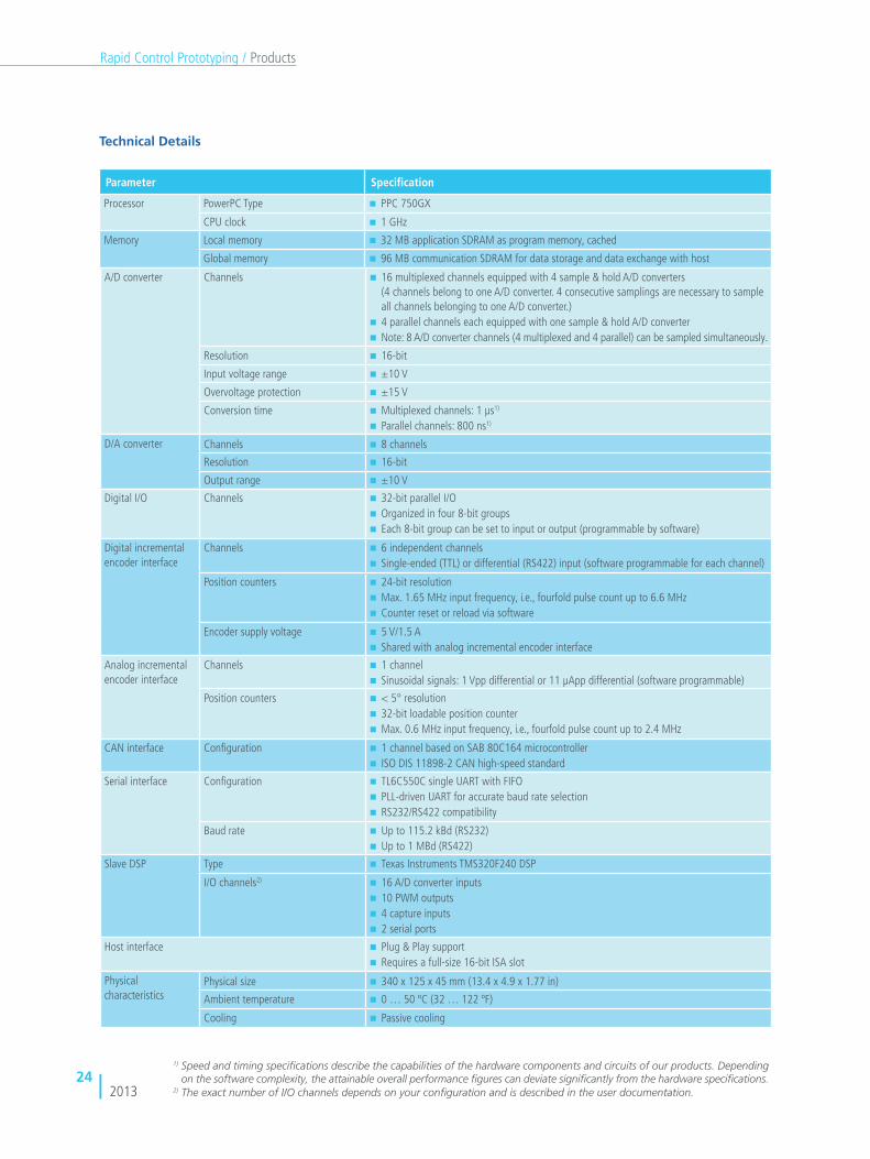
Technical Details
1) Speed and timing specifications describe the capabilities of the hardware components and circuits of our products. Depending on the software complexity, the attainable overall performance figures can deviate significantly from the hardware specifications.
Parameter Specification
Processor PowerPC Type PPC 750GX
CPU clock 1 GHz
Memory Local memory 32 MB application SDRAM as program memory, cached
Global memory 96 MB communication SDRAM for data storage and data exchange with host
A/D converter Channels
16 multiplexed channels equipped with 4 sample & hold A/D converters
(4 channels belong to one A/D converter. 4 consecutive samplings are necessary to sample
all channels belonging to one A/D converter.)
4 parallel channels each equipped with one sample & hold A/D converter
Note: 8 A/D converter channels (4 multiplexed and 4 parallel) can be sampled simultaneously.
Resolution 16-bit
Input voltage range ±10 V
Overvoltage protection ±15 V
Conversion time Multiplexed channels: 1 µs1)
Parallel channels: 800 ns1)
D/A converter Channels 8 channels
Resolution 16-bit
Output range ±10 V
Digital I/O Channels
32-bit parallel I/O
Organized in four 8-bit groups
Each 8-bit group can be set to input or output (programmable by software)
Digital incremental
encoder interface
Channels
6 independent channels
Single-ended (TTL) or differential (RS422) input (software programmable for each channel)
Position counters
24-bit resolution
Max. 1.65 MHz input frequency, i.e., fourfold pulse count up to 6.6 MHz
Counter reset or reload via software
Encoder supply voltage
5 V/1.5 A
Shared with analog incremental encoder interface
Analog incremental
encoder interface
Channels
1 channel
Sinusoidal signals: 1 Vpp differential or 11 µApp differential (software programmable)
Position counters
< 5° resolution
32-bit loadable position counter
Max. 0.6 MHz input frequency, i.e., fourfold pulse count up to 2.4 MHz
CAN interface Configuration
1 channel based on SAB 80C164 microcontroller
ISO DIS 11898-2 CAN high-speed standard
Serial interface Configuration
TL6C550C single UART with FIFO
PLL-driven UART for accurate baud rate selection
RS232/RS422 compatibility
Baud rate
Up to 115.2 kBd (RS232)
Up to 1 MBd (RS422)
Slave DSP Type Texas Instruments TMS320F240 DSP
I/O channels2)
16 A/D converter inputs
10 PWM outputs
4 capture inputs
2 serial ports
Host interface Plug & Play support
Requires a full-size 16-bit ISA slot
Physical
characteristicsPhysical size 340 x 125 x 45 mm (13.4 x 4.9 x 1.77 in)
Ambient temperature 0 … 50 ºC (32 … 122 ºF)
Cooling Passive cooling
2) The exact number of I/O channels depends on your configuration and is described in the user documentation.

252013
Rapid Control Prototyping / Products
Technical Data (AC Motor Control Solution for PHS-bus-based systems)
Parameter Specification
Digital input 8 channels, 0 ... 5 V, differential or single-ended. Default: 3 x single-ended for Hall sensor, 3 x differential for
incremental encoder, 2 x single-ended for bit in, frequency and duty cycle measurement
Digital output 10 channels, 0 ... 5 V, single-ended; 6 gate driver signals, 4 generic digital outputs (e.g. PWM synchronization
signals or bit out), optional: 12 additional gate driver signals with ACMC PWM Extension Board
Gate driver frequency 10 Hz ... 1 MHz
ADC 8 channels, software-configurable inpult voltage range (± 5 V, ± 15 V, ± 30 V), differential, 10 MSPS
DAC 2 channels, -10 ... 10 V (single-ended) or -20 ... 20 V (differential, reference to GND)
Resolver interface Max. position resolution 16 bit (depending on motor velocity). Generation of excitation signal (3,7,10 Vrms);
excitation frequency from 2 ... 20 kHz within 250 Hz steps (software-configurable)
RS422/RS485 SSI oder EnDat for connection of single/multi turn encoder
4 RS485 transceivers (Endat or SSI Interface)
Power supply for sensors 5 V and 12 V, 140 mA
Scope of Delivery (AC Motor Control Solution
for PHS-bus-based systems)
FPGA Base Board
I/O piggyback module for AC motor control applications
FPGA firmware for AC motor control applications
Simulink interface for AC motor control applications
Bracket for connecting I/O and mating connectors

262013
Rapid Control Prototyping / Products
Completely user-programmable via RTI FPGA
Programming Blockset
Utilizes the Xilinx® System Generator (XSG) Simulink®
Blockset
Offl ine Simulation in Simulink
Basic set of I/O drivers on board, I/O extendable
by piggyback modules
DS5203 FPGA Board
FPGA programmable per application
Purpose
The DS5203 FPGA Board can be adapted to various tasks,
so you can react fl exibly to tougher requirements like signal
conditioning, using new interfaces, or speeding up model
parts. FPGAs are especially useful for relieving the proces-
sor board of tasks such as signal preprocessing during ECU
development.
Application Areas
Running at 100 MHz, the DS5203 board is ideal for applica-
tion fi elds like engine knock, cylinder pressure analyses and
electric drive projects. The DS5203 works together closely
with application-specifi c XSG model libraries.
Programming via the RTI FPGA Programming
Blockset
The DS5203 FPGA Board is programmed via the RTI FPGA
Programming Blockset from dSPACE and the Xilinx System
Generator. These let you develop applications for the pro-
cessor board and the DS5203 together. You can test the
interaction between the processor application and the FPGA
application in offl ine simulation before implementing them
on the real-time hardware. This enables you to react fl exibly
to new requirements such as new interfaces or having to
accelerate the execution of submodels.
You can also use the RTI FPGA Programming Blockset Hand-
code Interface to program the DS5203.
Two Variants
The DS5203 is available with two different FPGAs:
DS5203 LX 50 includes a Xilinx Virtex®-5 LX50T-1C FPGA
consisting of 46,080 logic cells and 48 special DSP blocks.
This board offers a cost-effective solution for smaller
applications and starter systems.
DS5203 SX95 includes a Xilinx Virtex®-5 SX95T-2C
FPGA consisting of 94,298 logic cells and 640 special
DSP blocks. The large amount of DSP blocks help by
performing tasks such as fast, resource-saving multiplica-
tion.

272013
Rapid Control Prototyping / Products
Technical Details
ParameterSpecification
DS5203 LX50 DS5203 SX95
General User-programmable FPGA
FPGA Xilinx Virtex®-5 LX50T-1C
Logic cells: 46080 (Virtex-5 slices: 7200;
DSP slices: 48)
Distributed RAM: 480 kBits
Block RAM: 2160 kBits
Xilinx Virtex®-5 SX95T-2C
Logic cells: 94298 (Virtex-5 slices: 14720;
DSP slices: 640)
Distributed RAM: 1520 kBits
Block RAM: 8784 kBits
Device timing 100 MHz
Digital I/O 16 channels, usable as input or output
Input Maximum input voltage 15 V
Digital input: Threshold adjustable for each channel from 1 V to 7.5 V
Output Digital output: Push-pull drivers; one output voltage can be selected for all channels: 3.3 V or 5 V
Analog I/O Input 6 channels
Resolution 14-bit pipelined
Sampling rate 10 MSPS
Input voltage range selectable for each channel: ±5 V or ±30 V
Output 6 channels
Resolution 14-bit
Update rate 10 MSPS
Output voltage range: ±10 V
Further interfaces Slot for one I/O module for extending the analog and digital I/O
Connection for the APU (angular processing unit) bus
Physical characteristics Physical size 340 x 125 x 15 mm (13.4 x 4.9 x 0.6 in)
Ambient temperature 0 ... 55 ºC (32 ... 131 ºF)
Power supply +5 V ±5%, 2.5 A
+12 V ±5%, 0.7 A
-12 V ±5%, 0.1 A
Relevant Software and Hardware
Software
Required Real-Time Interface (RTI)
RTI FPGA Programming Blockset FPGA Interface
RTI FPGA Programming Blockset Handcode Interface
Xilinx® ISE® Foundation and System Generator for DSP
Optional XSG Electric Components Library
XSG Utils Library
XSG ACMC Library
Hardware
Optional DS5203M1 Multi-I/O Module
EV1099: Resolver SC Module for DS5203

282013
Rapid Control Prototyping / Products
DS5203M1 Multi-I/O Module
Technical Details
Parameter Specification
Digital I/O 16 channels, usable as input or output
Input Maximum input voltage: 15 V
Threshold for each channel adjustable from 1 V to 7.5 V
Output Push-pull drivers
One output voltage can be selected for all channels: 3.3 V or 5 V
Analog I/O Input 6 channels
Resolution 14-bit pipelined
Sampling rate 10 MSPS
Input voltage range selectable for each channel: ±5 V or ±30 V
Output 6 channels
Resolution 14-bit
Update rate 10 MSPS
Output voltage range: ±10 V
Sensor supply Adjustable
Output voltage range: 2 V to 20 V
EV1099: Resolver SC Module for DS5203
The EV1099 Resolver SC Module is a transfer element for the
DS5203 FPGA Board or the DS5203M1 Multi-I/O Module.
It offers special signal conditioning for electric drive applica-
tions, such as transformers for resolver simulation.
Additional features:
Configurable audio transformer for each of
the 6 DAC channels
Switchable 220 Ω resistor for each of
the 6 ADC channels
The module can be installed in a dSPACE Simulator Full-Size
or Mid-Size. It is connected via ribbon cable to the DS5203
or DS5203M1, which are pin-compatible.
The DS5203M1 Multi-I/O Module is a piggyback module
for the DS5203 FPGA Board. It extends the available digital
and analog I/O to give you more flexibility.

292013
Rapid Control Prototyping / Products
Battery Cell Voltage Measurement
and Balancing
Application Areas
The Battery Cell Voltage Measurement and Balancing system
enables highly precise measurement and control of cell
voltages in lithium-ion batteries and allows the development
of algorithms for battery management. The system can be
installed directly in a vehicle and features cell-balancing
functions that maintain the charge states of individual cells
at the same level to ensure safe operation. This prevents
thermal instability and extends battery life.
Manual and Automatic Balancing
Two operation modes are available: The manual balancing
mode gives users complete freedom to balance cells
individually or collectively, and at any desired intervals.
The automatic balancing mode is a comfort function that
specifies target voltages and switch-off times, leaving users
free to focus on the more important algorithms.
Reliable Safety Features
Because of the high voltages of Li-ion batteries, the system
provides various safety features. These include warnings
about hardware, communication and synchronization
errors, and also about overheating, isolation faults, and
cell undervoltages and overvoltages.
For the emulation of high-voltage batteries, please
refer to the EV1077 Battery Cell Voltage Emulation
Board (p. 52).
Technical Details
Modular system supporting 6 to approx. 200 cells,
installable in a vehicle
Intersil® ISL78600 BMS IC
Cell voltage measured with ±3 mV accuracy
User-defined sampling rate (max. 1 kSPS)
Plug-on modules for quick replacement of balancing
resistances. Resistance values up to 10 Ohm
S-function-based Simulink® blockset (RTI Ethernet
(UDP) blockset additionally required)
Two balancing modes:
Manual mode with full user control
Configurable automatic mode
Synchronized battery cell measurement
Comprehensive error detection features
Isolation monitoring device connectable to each
EV1093

302013
Testing with Hardware-in-the-Loop Simulation
Function tests are possible at an early development
stage, even before all parts are available in reality
Laboratory tests reduce time and costs and take place
under controlled conditions
Failures, and the ECU’s behavior in what are normally
dangerous situations, can be tested with no risk for
the driver or the controlled machine.
The tests are reproducible and can be automated
Advantages of HIL Simulation
After the ECU functions have been developed and imple-
mented on the production ECU, they have to be tested
thoroughly. With hardware-in-the-loop (HIL) simulation,
you can easily cover all the different motor varieties and
their ECUs.
The ECU’s environment (interacting components or even
a whole system) is simulated. This has several advantages:
Challenges of Testing ECUs for Electric Motors
Electric motors have been becoming more and more power-
ful in a wide range of applications. The conventional brushed
direct current (BDC) motors were replaced by brushless direct
current (BLDC) motors. The ECUs controlling the electric
motors provide the actuation power directly. This is un-
like other applications, where thermodynamic or hydraulic
power is controlled by means of low auxiliary power coming
from the ECU.
dSPACE offers products and solutions for PHS-bus-based HIL
simulation as well as for SCALEXIO HIL systems.
ECUs for controlling electric motors are often incorporated
into complex and distributed vehicle functions, so it is
essential to test their interaction with other ECUs.
Special solutions are needed for interfacing the ECU:
High power level
High dynamics
Special I/O, e.g., for encoders and resolvers
HIL Interfaces
An ECU or other system for controlling electric motors can
be accessed by the HIL simulator at different levels. Which
interface to use depends on the testing purpose and project
conditions:
Signal level: Simulation of the power electronics,
the electric motor, and the mechanical environment
Very scalable, as parameters can be set fl exibly
regardless of power level
Full access to the model
ECU must be opened
Electric power level: Simulation of the electric motor
and the mechanical environment
Production ECU can be used
Full access to the model
Motor parameters can be set fl exibly within
a certain power range
Mechanical level: Simulation of the mechanical
environment
Testing of mechanical parts

312013
Hardware-in-the-Loop Simulation
ElectricMotor
Controller
ECU
Current Signal
Position Signal
3 Phase Voltages
VehicleApplication
Transmission
Controller Power Stage Electric Motor Mechanics
Signal Level Electric Power Level Mechanical Level
ApplicationController Sensor Signals
PowerConverter
For further product information, please see:
DS5203 FPGA Board (PHS-bus only), page 26
Electric Motor HIL Solution (PHS-bus only), page 40
Programmable Generic Interface, page 47
Electrical Load Modules, page 48
Battery Cell Voltage Emulation, page 52
Battery Simulation
dSPACE offers special hardware and software for battery
simulation:
Real-time hardware for HIL tests with high voltage
accuracy and galvanic separation
Simulation models for lithium-ion batteries and
nickle-metal hydride batteries for realistic battery
management tests
Simulation Models
For real-time simulation of an electrical system, dSPACE
provides the ASM Electric Components Library for processor-
based simulation and the XSG Electric Components Library
for FPGA-based Simulation.
Applications can range from electric drives and inverters
for closed-loop simulation with an electric drive control-
ler, to a complete automotive electrical system including a
battery, starter, alternator, and loads. Typical use cases are
the simulation of realistic battery behavior during starter
activation, electric drives that are integrated into a hybrid
electrical vehicle powertrain, etc.
ASM Electric Components Model, page 54
XSG Electric Component Library, page 56
XSG Utils Library, page 57
JMAG-RT Parameterization Support, page 58
DS2655 FPGA Base Module (SCALEXIO only), page 45

322013
Hardware-in-the-Loop Simulation / Use Cases
Task
Drives with brushless direct current (BLDC) motors are popu-
lar because they are simple and robust. Often they are oper-
ated without any position sensors like Hall sensors and are
Challenge
During the operation of BLDC motors only two of the three
phases are triggered at a time. In the third, untriggered
phase the electromotive voltage is induced, which affects
the ECU terminals. In sensorless control, the ECU measures
this voltage for position detection.
Solution
A dSPACE Simulator equipped with a DS5203 board and
XSG Electric Component Models enables the complete simu-
lation of BLDC motors at electric power level. No real parts
are required. Due to the characteristics of BLDC operation
described above, the simulation comprises a current emula-
tion and also a voltage emulation.
Simulating Brushless DC Motors at Electric Power Level
UDhAhB
hChA
hB
hC
zA-
zA+
zB-
zB+
zC-
zC+
commutation logic
iB
iC
iAA
A
C
C
B
BHall sensors
Stator windings
Stator
Permanent
magnets
Rotor
used in continuously running pumps, electric fuel pumps,
selective catalytic reduction (SCR) systems, and so on.
Above: Sensorless control of a simulated BLDC motor. The triggered
phase and freewheeling phase are simulated in current mode, the
floating phase is simulated in voltage mode.
Below: Detail measurement of the floating phase: Accurate
reproduction of the pulsing feedback voltage
Use Cases

332013
Hardware-in-the-Loop Simulation / Use Cases
NetworkInterface
ANALOGIN1
ANALOGIN2
START
RESET
QUICKSTOP
ENABLE
Hiperface
EnDat 2.1
SSI
TTL Encoder
Resolver
Power Supply
D.C. link
Brakingresistor
U
V
W
L-
L+
RB
L3
L2
L1
Encoder
Encoder
Encoder
Encoder
Resolver
Task
In this application, the software for a servocontroller can be
used for almost all electric motors in a power range from a
few watts to several hundred kW. The ECU for the servo-
controller contains a wide range of functions that have to
Challenge
The test system has to cover a wide range of electric motor
power variations. As real parts would necessitate time-con-
suming modifications to the test system, simulation models
are used. They have to be as precise as possible.
Solution
A DS1005 Processor Board and the DS5202 Electric Motor
HIL Solution are used for the real-time simulation. The
simulation models use components from the ASM Electric
Components Library. The FPGA of the DS5202 handles the
time-critical I/O parts for the simulation model, enabling
moderate sample rates.
The dSPACE EMH Solution (p. 40) is ideal for this application,
as it offers emulation for almost all industrial position sensor
systems such as resolvers, TTL encoders, sine encoders and
Hall sensors, and also protocol-based sensors such as SSI,
EnDat 2.a and Hiperface®.
Testing a Servocontroller at Signal Level
work with various configurations of motors, power stages,
sensors and bus systems. A wide range of configurations
have to be tested.
Example application: either the servo controller or the electric motor
can be simulated with dSPACE Simulator.

342013
Hardware-in-the-Loop Simulation / Use Cases
Simulating Electric Power Steering Systems at Electric Power Level
Task
Electric power steering (EPS) systems support the driver dur-
ing steering. A torque sensor measures the steering move-
ment and sends this data to the EPS ECU, which causes
the EPS electric motor to support and enforce the move-
ment. As the EPS electric motor acts directly on the steering
rod, the vehicle can be steered even without the driver's
interaction. This enables fully automated parking as well
as interaction with the electronic stability control (ESC) to
support the driver.
Challenge
The signals of ECUs for EPS often cannot be accessed at
signal level. HIL simulation is therefore performed at power
level. The ECUs have to be connected to the real motor
either at mechanical level or by simulation at electric power
level.
The electric power level requires real currents and a simula-
tion for the motor. This solution is quite flexible and can
be adapted quickly: for example, to simulate different mo-
tor types. The simulation can also be combined with HIL
simulation for an ESP.
Solution
In both cases dSPACE Simulator is equipped with a DS5203
FPGA Board running the XSG electric component´s e-motor
models. Electronic load modules (p. 48) provide the real
current for simulation at electric power level. dSPACE Auto-
motive Simulation Models for vehicle dynamics are used
for simulating the actual physical vehicle characteristics,
including the steering system for the EPS and the brake
hydraulics for the ESP.
Overall integration of EPS electric motor simulation at electric power level, together with an HIL simulation for an ESP.
Position Sensor Simulation
DS5203
ASM (e.g. Gasoline, Transmission)
ASM Vehicle
Node #2: EPS HIL
TSensor
APU
wEPS
TEPS
EPSECU
Torque Sensor Simulation
Node #1: ESP HIL
I/O for VSD
CAN Gateway for SensorCluster
Real Sensor Cluster
VSD(Valve Current Detection)
ESP ECU
eEPS
Electric Motor Simulation
Electronic Loads
DS5203 with XSG EC models
DS5380
ASM Driver, Maneuver Scheduler ASM Traffic
Fast Tasks
FEPS
xRod
xRod
iEPS
iEPS
iEPS
MDoFVehicleDynamics
Steering System
Brake Hydraulics
I/O for ESP

352013
Hardware-in-the-Loop Simulation / Use Cases
Developing Mechatronic Steering Systems
Task
The steering system and its characteristics decisively affect
a vehicle's driving behavior and feeling. Haptic feedback
plays a vital role here, as it gives the driver vital information
about the road and the vehicle. It is only when the overall
Challenge
The test system needs to provide haptic feedback and offer a
close-to-reality environment simulation for a realistic steering
feeling and driving behavior. Its purpose is to give an initial
impression at an early stage of product development. The
simulation model has to take extra features into account,
such as automatic parking and lane-keeping assistants for
enhancing comfort and active safety.
steering system is integrated into the vehicle that develop-
ers can actually experience it. As this subjective impression
is very important and the integration process is expensive,
another approach is needed.
Solution
dSPACE combines a HIL steering test bench and a static driv-
ing simulator that enables pre-calibration on a virtual experi-
mental vehicle. The test apparatus consists of the real steer-
ing system with its actuators, and the driving simulator with
a load machine for the steering wheel, the accelerator pedal,
and the brake pedal. Both are coupled to the dSPACE Auto-
motive Simulation Models (ASMs) running on a quad-core
DS1006 Processor Board. The ASMs are open Simulink models
for the real-time simulation of passenger cars, trucks and
trailers that simulate the vehicle's vertical, longitudinal and
lateral dynamics as a multibody system with 24 degrees
of freedom.
Visualization is done with dSPACE
MotionDesk using small LCD moni-
tors representing the outside and
inside rear-view mirrors. The sensa-
tion of driving is further intensifi ed
by road and engine noises.
The system is used not only to inves-
tigate and adjust steering systems,
but also to run driver assistance sys-
tems such as lane departure warning
systems.
Functional diagram of the HIL steering
test bench driving simulator and the
camera HIL.
Vehicle simulation
Steering wheel angle
EPS test system with HIL
Visualization
Optical feedback
Accelerator and brake pedal positions
Steering torque Torque interface
Driving simulator
Vehicle response
Rack force
Rack position

362013
Hardware-in-the-Loop Simulation / Use Cases
Simulating Automated Manual Transmissions
Task
Automated manual transmission (AMT) operates similarly to
manual transmission, except that it does not require clutch
actuation or shifting by the driver. Automatic shifting is
controlled electronically (shift-by-wire) and performed by
electric motors or hydraulically.
In this application, an ECU for an AMT controls three elec-
tric direct current (DC) motors, one for the clutch and one
Challenge
To test the ECU with real motors as well, the test system
allows switching between electric motors as real parts and
simulated electric motors by using simulation models. High
currents up to 60 A are needed to simulate the inrush cur-
rent of the DC motors.
Solution
A dSPACE hardware-in-the-loop simulator is equipped
with a DS2211 HIL I/O Board, which provides various in-
terfaces for connecting the ECU. New ECU variants can
easily be adapted to the simulation just by changing the
cable harness. Electronic load modules and a DS5203
running XSG Electric Components Library models emu-
late the electric motors. To test the ECU's behavior dur-
ing electric failures, high-current failure simulation can be
performed. dSPACE Automotive Simulation Models (ASM)
such as ASM Drivetrain are used for simulating the actual
physical gearbox characteristics.
Hardware-in-the-loop simulator for
AMT simulation with 12 electronic
loads (page 48).
each for the longitudinal and the lateral movement of the
gear selector level. The ECU chooses the gear according to
the motor rotation speed and accelerator pedal position. It
activates the clutch and engages the appropriate gear via
the shift and the selector motor. It is also possible to shift up
and down manually without engaging the clutch.

372013
Hardware-in-the-Loop Simulation / Use Cases
Simulation for Battery Management Systems
Task
The battery management system (BMS) monitors the electric
and thermal state of the batteries used in hybrid or electric
vehicles. It takes the drive's requirements and environment
impacts into account, and influences each battery and its
cells to provide the energy needed and to maintain opti-
mal operation conditions for good performance and long
battery life.
Solution
The typical HIL simulation setup for battery management
system tests comprises a processor board, HIL I/O boards
for I/O interfaces, a board for CAN interfaces, and a failure
insertion unit for testing electric failures. Restbus simulation
is used for simulating unavailable cell stacks. dSPACE offers
specialized hardware and software for testing a BMS, for
example, the EV1077 Battery Cell Voltage Emulation Board
(p. 52) for simulating high-voltage batteries at cell level
and the ASM Multicell Models (p. 55). The test system can
virtually represent the electrical and thermal properties of
a battery down to cell level.
Other components are high-precision voltage sources from
0 to 6 V, which can take the load of the current flowing in cell
balancing. Typical requirements for cell voltage simulation
are a precision of about 2 mV and a current up to a few
hundred mA. The voltage sources are galvanically isolated
and can be switched in sequence to form cell modules. The
voltage of the entire battery can be simulated this way.
Failure simulations such as a break in the measurement
cable or the cell connectors (galvanic disconnection of the
cell stack) can be run. The voltage sources are connected
to the processor board via an LVDS or Ethernet interface,
with connection distances of up to 5 m with copper cabling
and up to 100 m with optic cabling. All the cell voltages in
a battery can be adjusted in less than 1 ms.
Switch (relay)
High voltage measurement
Isolation monitoring
High voltage simulation
I/0
Relay control
CANCAN restbus simulation
Electric I/O
CAN
DS1006
DS4121
DS2211
DS4302
Isolation fault simulation
Cell voltage/temperature simulationFailure simulation
PHS bu
s
Temperature sensor simulation
CE 1 ... nBMS
BMS: Battery Management System
CE: Cell ECU
LVDS: Low Voltage Differential Signaling
LVDS
Failure simulation
Failure simulation
Example of a HIL simulation setup for a battery management system.
Challenge
Batteries for electric vehicles have extremely high voltages
and currents, so the BMS is safety-critical. To ensure safety
during HIL simulation, the overall voltage might have to be
scaled down. Electrical failure simulation is also needed to
make sure the BMS reacts correctly in all circumstances.
These are typical failure tests:
Broken wires
Short circuits
Loose contacts

382013
Hardware-in-the-Loop Simulation / Use Cases
Task
A hybrid electric powertrain typically contains several net-
worked ECUs which the functions are distributed to. The
functions, such as overlaid hybrid control functions, can be
implemented on separate ECUs or combined with other
functions. As these functions need to be extremely reliable,
the development and test requirements are high.
Challenge
To set up a typical realistic hybrid powertrain, two parallel
CAN structures have to be built: A powertrain or vehicle CAN
and a private hybrid CAN. The powertrain CAN connects
the standard ECUs such as the engine ECU and transmission
ECU, and others such as the ESP ECU which can also be
simulated by their CAN messages. The hybrid-specifi c ECUs
are usually connected to the hybrid CAN.
Testing ECU Networks of Hybrid Electric Powertrains
Solution
For hardware-in-the-loop simulation, you can connect all
existing powertrain ECUs with the HIL simulator. The simu-
lator is equipped with at least one processor board and
various interface boards. Powertrain components that are
not yet available are emulated via restbus simulation. Testing
usually also covers several CAN networks. The modularity
of the dSPACE hardware means that the simulators can be
confi gured for various applications. All known hybrid vehicle
versions and ECU or CAN confi gu rations are possible.
For integration testing, a hybrid electric powertrain simulator
can be extended to simulate a full virtual hybrid electric
vehicle by adding further racks to cover all the other ECUs
in the vehicle, such as ESP.
If the HIL tests cover the simu lation of the electric motor
and the battery, safety aspects make it necessary to separate
the HIL simulations. The simulator racks are then connected
via Gigalink. This high-speed serial data transmission via
fi ber-optic cable and 1.25G bit/s technology provides very
fast information exchange.
Valve Drawer
Load FIU
TransmissionECU
EngineECU
EPSECU
Powertrain CAN Hybrid CAN
Transmission EngineElectric Motor
Battery
GigalinkGigalink
HybridPowertrain
ECU
E-MotorECU
BatteryManagement
System
Extensionby furtherracks andECUsto fullVirtual Vehicle
Node #1 Node #2 Node #3 Node #X

392013
Hardware-in-the-Loop Simulation / Publications
Additional Information
You can download success stories, articles and product
information on drive applications at www.dspace.com under
"Downloads".
Available Publications (Partial List)
Title Author Published at
Hardware-in-the-Loop Test of Battery Management Systems Markus Ploeger (dSPACE GmbH), Joerg Bracker
(dSPACE GmbH), Dr. Hagen Haupt (dSPACE GmbH)
SAE World congress, Apr 2013
Hardware-in-the-Loop Simulation
of Electrified Powertrains
Tino Schulze (dSPACE GmbH), Matthias Deter
(dSPACE GmbH), Markus Ploeger (dSPACE GmbH)
MTZ - Motortechnische Zeitschrift,
Dec 2012
Leistungselektronikmodelle für Hardware-in-the-Loop-Simulation Dr. Thomas Schulte (HS OWL), Axel Kiffe (HS OWL),
Frank Puschmann (dSPACE GmbH)
SPS IPC Drives 2012, Nürnberg,
Sep 2012
Hardware-in-the-Loop-Testing of Battery Management Systems Dr. Claus Abicht (dSPACE GmbH, ), Markus Ploeger
(dSPACE GmbH), Joerg Bracker (dSPACE GmbH), Dr.
Hagen Haupt(dSPACE GmbH)
HDT, München, Apr 2012
Concept of a New Hardware-in-the-Loop Driving Simulator for
the Model-Based Design of Mechatronic Steering Systems
Steffen Stauder (University Kaiserslautern), Prof.
Dr. Steffen Müller (University Kaiserslautern),
Markus Ploeger(dSPACE GmbH), Andre Lehnsmeier
(dSPACE GmbH)
FKFS Symposium, Stuttgart,
Mar 2012
HIL Simulation of Power Electronics and Electric Drives for
Automotive Applications,
Dr. Thomas Schulte (HS OWL), Axel Kiffe(HS OWL),
Frank Puschmann (dSPACE GmbH)
16th International Symposium
on Power Electronics, EE2011,
Novi Sad, Oct 2011
HIL-Test von Batteriemanagementsystemen Markus Ploeger (dSPACE GmbH), Joerg Bracker
(dSPACE GmbH), Dr. Hagen Haupt (dSPACE GmbH)
Automobil Elektronik, Oct 2011
HIL-Prüfstand zum Test von Batterie-Management-Systemen Markus Ploeger (dSPACE GmbH), Joerg Bracker
(dSPACE GmbH), Dr. Hagen Haupt (dSPACE GmbH)
Electronic Automotive, Jul 2011
Hardware-in-the-Loop-Simulation for electric Drives Dr. Thomas Schulte (dSPACE GmbH), Frank
Puschmann (dSPACE GmbH), Dr. Harald Wertz (LTi
DRiVES GmbH)
SPS/IPC/DRIVES10, Nürnberg,
Nov 2010
Real-Time Simulation of Electric Drives by Electronic Load-
Emulation
Dr. Thomas Schulte (dSPACE GmbH), Jörg Bracker
(dSPACE GmbH)
IFAC Symposium, Munich,
Jul 2010
Electric Motors: Hardware-in-the- Loop Testing at Full Power Nils Holthaus (dSPACE GmbH), Markus Plöger
(dSPACE GmbH), Dr. Thomas Schulte (dSPACE GmbH)
Automobil-Elektronik, Feb 2010
Hardware-in-the-Loop: The Technology for Testing Electronic
Controls in Automotive Engineering
Dr. Peter Wältermann (dSPACE GmbH) 6th Paderborn Workshop
"Designing Mechatronic
Systems", Paderborn, Apr 2009
Hardware-in-the-Loop Simulation for Hybrid Electric Vehicles Syed Ali (dSPACE Inc), Amanjot Dhaliwal (dSPACE Inc),
Shreyas C. Nagaraj (dSPACE Inc)
SAE World Congress, Apr 2009
HIL Simulation for Mechatronic Automotive Electronic Control
Units: Current applications in vehicle dynamics and electric
power steering
Andreas Filgerdamm (dSPACE GmbH), Markus
Plöger (dSPACE GmbH), Dr. Thomas Schulte
(dSPACE GmbH)
Elektronik automotive, Mar 2009
HIL Simulation for Mechatronic Automotive Electronic Control Units Andreas Filgerdamm (dSPACE GmbH), Markus
Plöger (dSPACE GmbH), Dr. Thomas Schulte
(dSPACE GmbH
Elektronik automotive, Mar 2009
Hardware-in-the-Loop Test Systems for Electric Motors
in Advanced Powertrain Applications
Dr. Thomas Schulte (dSPACE GmbH), Dr. Herbert
Schütte (dSPACE GmbH), Dr. Andreas Wagener
(dSPACE GmbH), Dr. Peter Wältermann (dSPACE GmbH)
SAE World Congress, Apr 2007
Test elektrischer Antriebe für Hybridfahrzeuge mittels Hardware-
in-the-Loop Simulation
Jürgen Klahold (dSPACE GmbH), Dr. Thomas Schulte
(dSPACE GmbH), Dr. Andreas Wagener
(dSPACE GmbH)
HDT, March 2007

402013
Hardware-in-the-Loop Simulation / Products
High-precision digital capturing of
3-phase PWM signals
Fast signal measurement and analysis
Simulation of various position sensors
High timing resolution
Various additional multipurpose signals
EMH SolutionElectric motor hardware-in-the-loop simulation
Purpose
The EMH (electric motor HIL) solution is based on the DS5202
FPGA Base Board. It gives you all the I/O channels that are
needed for HIL simulation of electric motors, such as high-
precision digital capturing of 3-phase PWM signals and
position sensor simulation, plus several digital and analog
I/O channels. It combines the features of the DS5202 PWM
and PSS Solutions with many additional multipurpose chan-
nels, and enables effi cient testing of electronic control units
(ECUs) for electric motors on a single I/O board.
Use Case
A typical use case is a hardware-in-the-loop (HIL) simulation
where the electric motor including the electronic power
stage is simulated with the dSPACE modular real-time
processing hardware (DS1005/1006). Simulation models
like the ASM Electric Components models are used for
simulating the electric components. The gate driver sig-
nals (typically PWM signals) coming from a controller are
measured by the DS5202 EMH Solution, and calculated
motor current signals are sent back to the controller by
means of analog voltage signals, which can also be provided
by the DS5202 EMH Solution. In addition, the DS5202 EMH
Solution provides the necessary position sensor signals for
the ECU.
Applications
The DS5202 EMH Solution combined with a simulation
model allows you to measure the signals of up to 2 electric
machines with up to 8 power switch control signals each,
such as IGBTs (insulated-gate bipolar transistors). There
is a choice of three operating modes: software polling,
external interrupt source, and internal pulse center interrupt
source, meaning clock generation based on the measured
PWM signals, which is the most suitable way of avoiding
beat effects.
The current feedback signals for the ECU can be simulated
by using the board’s fast analog output channels. For posi-
tion sensor simulation, the board is equipped with four
independent angular processing units (APUs) that receive the
angular velocity from the model and calculate the position
signal. Since each APU’s sample time is 12.5 ns, it provides
a position signal with a high timing and angular resolution.
dSPACE Products

412013
Hardware-in-the-Loop Simulation / Products
Features
Measuring duty cycles and periods of up to 16 PWM
signals
Separate access by groups of 8 channels via Simulink
interface; capture mode adjustable independently for
each group
Evaluating dead time between adjacent channels
Generating interrupts and triggers to external devices at
the center position of the PWM period
Key Features
1 digital and 1 analog sensor (three signals each, one
protocol-based sensor) and 3 independent angle-based
digital signals can be simulated in parallel
Different sensor types are possible:
Analog type: resolver, sinus encoder, user-defi ned
waveform
Digital type: TTL encoder, Hall position sensors,
user-defi ned waveform
Oversampling and downsampling for interrupt generation
Using an external trigger as a latch source for the time
measurement and interrupt for the real-time model
8 channels can alternatively be used as general purpose
inputs (digital or PWM inputs)
High timing resolution
Adjustable debounce time
Protocol type: SSI, Hiperface® or EnDat sensor simulation
All sensor simulation groups can be arbitrarily allocated
to up to four independent simulated shafts (APUs)
Resolver failure simulation (please refer to PSS solution)
APU-angle-dependent arbitrary waveform generation
High precision and high timing resolution
Onboard signal conditioning
Full differential I/O for all analog signals
PWM Measurement
Position Sensor Simulation
Gate control signals
RTI Blockset
PHS bus DS1005/DS1006
DS5202
I/O module
ECUCurrent signals
Hall/encoder
Resolver

422013
Hardware-in-the-Loop Simulation / Products
Analog Sensors
Resolver:
Number of pole pairs
Output mode
Direct (single-ended)
Direct (differential)
Transformer (standard)
Amplitude of excitation signal
Transformation ratio
Sinus encoder:
Lines per revolution
Output mode
Direct (single-ended)
Direct (differential)
Amplitude of output voltage signal
DC offset of output signal
Default or user-defined index signal
User-defined waveform:
Separate waveform definition for each of the three
analog channels
Waveform repetition per revolution
DC offset
Digital Sensors
TTL encoder:
Lines per revolution
Default or user-defined index signal
Hall encoder:
Number of pole pairs
Start and end positions of pulse for all three digital
channels separately
User-defined waveform:
Waveforms per revolution
Waveform definition for each of the three digital
channels separately
Protocol Sensors
SSI Encoder:
Data frame length
Monoflop time
Bit code
Type of parity bit
Number of multiturn bits
Definition of data frame
Hiperface Encoder:
Baud rate
Type of parity bit
Number of multiturn bits
Driver active time
Pause time
Bus dead time
Enable parameter channel
Definition of data frame
EnDat Encoder:
Data frame length
Recovery time
Calculation time
Bit code
Number of multiturn bits
Enable memory access
Memory access time
Definition of data frame

432013
Hardware-in-the-Loop Simulation / Products
In addition to the EMH Solution, a PWM Measurement and a Position Sensor Simulation Solution are also available.
Other dSPACE products for hardware-in-the-loop simulation:
DS5203 FPGA Board (p. 26)
FPGA programmable per application
Completely user-programmable via RTI FPGA Programming Blockset
Utilizes the Xilinx® System Generator (XSG) Simulink® Blockset
Offline simulation in Simulink
Basic set of I/O drivers on board, I/O extendable by piggyback modules
Multipurpose Channels
Features
7 analog output channels
6 analog input channels (2 channels shared with resolver
simulation)
10 digital outputs
3 digital and PWM outputs (shared with position sensor
simulation)
1 digital input; 16 digital/PWM input (freely accessible
to each of the 16 center aligned input channels)
1 RS485 interface for LTi ServoOne TWINsync interface

442013
Hardware-in-the-Loop Simulation / Products
Scope of Delivery
FPGA Base Board
I/O piggyback module for DS5202 EMH applications
Slot module for DS5202 EMH applications
FPGA firmware for DS5202 EMH applications
Simulink® interface for DS5202 EMH applications
Parameter Specification
Timing resolution 12,5 ns
Frequency range Max. frequency range 39 Hz ... 2 MHz
Digital inputs 16 channels: maximum input voltage +5 V, overvoltage protection ±50 V
Technical Data for PWM Measurement
Parameter Specification
Timing resolution 12,5 ns digital / 100 ns analog
Angular precision (APU) 32 bits
Angular precision (resolver) 0.1° (depending on the settings)
Delay for resolver feedback signals Min. 1.6 µs (adjustable up to 400 µs)
Resolution of analog input signals 14 bits (10 MSPS)
Resolution of analog output signals 12 bits (10 MSPS), based on the user-specified voltage range (10 MSPS)
Analog input range ± 30 V differential, ± 15 V single-ended, overvoltage protection ±50 V
Analog output range ± 20 V differential, ± 10 V single-ended, overvoltage protection ±50 V
Digital output Encoder 5 V, TTL, max. 40 mA, overvoltage protection ±50 V
Independent angle-
based signals
5 V, TTL, max. 40 mA, overvoltage protection ±50 V
Technical Data for Position Sensor Simulation
Parameter Specification
Analog outputs 6 channels: ± 10 V, 12-bit (10 MSPS), overvoltage protection ±50 V
1 channel: 0 ... 10 V, 14-bit (1 MSPS), overvoltage protection ±50 V
Analog inputs 3 channels: inpult voltage range (±30 V ), differential, 14-bit (10 MSPS), overvoltage protection ±50 V
1 channel: inpult voltage range (±30 V ), differential, 16-bit (1 MSPS), overvoltage protection ±50 V
Digital outputs 13 channels: 5 V, TTL, max. 40 mA, overvoltage protection ±50 V, (3 channels shared with position sensor
simulation)
Digital inputs 1 channel: 0...+20 inpult voltage range, threshold adjustable from 1V to 8.5V, overvoltage protection ±50 V
16 channels: 0...+20 inpult voltage range, up to 80MHz PWM measurement, threshold adjustable from 1V
to 8.5V, overvoltage protection ±50 V
RS485 SSI sensor simulation
Optionally: Hiperface® or EnDat sensor simulation
LTi ServoOne TWINsync Interface (to control a ServoOne inverter by dSPACE real-time hardware)
PWM control
Torque control
Speed control
Position control
Technical Data for Multipurpose Channels

452013
Hardware-in-the-Loop Simulation / Products
Highlights
User-progammable FPGA
Flexible board for special I/O solutions
Up to 5 piggyback modules for I/O can be added
DS2655 FPGA Base ModuleI/O board with user-programmable FPGA for use in SCALEXIO Systems
Application Area
The DS2655 FPGA Base Module has been designed for
SCALEXIO HIL applications that require very fast, high-
resolution signal processing, for example:
Hybrid vehicle applications
Electric drive applications
Wind energy converters
Processor-based electric motor simulation
FPGA-based electric motor simulation
Key Benefi ts
The DS2655 includes a powerful, freely programmable fi eld-
programmable gate array (FPGA), the Xilinx® Kintex™-7 160T.
To include I/O channels, you connect up to fi ve I/O modules
to the board.
Failure simulation can be added for each I/O module by
using an additional FIU module.
Programming the FPGA
Programs for the DS2655 FPGA Base Module's FPGA are
programmed with the RTI FPGA Programming Blockset.
These programs are downloaded to the FPGA via dSPACE
Confi gurationDesk.
You can test the program in offl ine simulation before imple-
menting it on the real-time hardware. This enables you to
react fl exibly to new requirements, such as new interfaces
or having to accelerate the execution of submodels. The
DS2655 works together closely with application-specifi c
XSG model libraries (p. 56/57).
DS2655M1 I/O Module
The DS2655M1 is a piggyback module for the DS2655 FPGA
Base Module. It contains the digital and analog I/O chan-
nels needed for electric drives applications.

462013
Hardware-in-the-Loop Simulation / Products
Technical Details DS2655
Parameter Specification
General User-programmable FPGA
FPGA Xilinx® Kintex™-7 160T
Logic cells: 162240 (DSP slices: 600)
Distributed RAM: 480 kBits
Block RAM: 11700 kBits
Connector for I/O modules 5
Device timing 125 MHz
Internal communication interface IOCNET
Physical characteristics Physical size 205 x 100 x 20 mm (8.1 x 3.9 x 0.8 in)
Power supply 24 V
Technical Details DS2655 M1
Parameter Specification
Digital I/O 10 channels, usable as input or output
Input Maximum input voltage: 15 V
Threshold for each channel adjustable from 1 V to 7.5 V
Output Push-pull drivers
One output voltage can be selected for all channels: 3.3 V or 5 V
Analog I/O Input 5 channels
Resolution 14 bit
Sampling rate 4 MSPS SAR
Input voltage range selectable for each channel: ±5 V or ±30 V
Output 5 channels
Resolution 14 bit
Update rate 7,8125 MSPS
Output voltage range: ±10 V
Sensor supply Adjustable
Output voltage range: 2 V to 20 V
Physical characteristics Physical size 208 x 100 x 18 mm (8.2 x 3.9 x 0.7 in)
Power supply 24 V
Relevant Software
Software
Required RTI FPGA Programming Blockset FPGA Interface
ConfigurationDesk – Implementation Version (SCALEXIO)
Xilinx® ISE® Design Suite WebPACK and System Generator for DSP (only for blockset) or Xilinx ISE Design Suite DSP / System Edition
Optional RTI FPGA Programming Blockset Handcode Interface
XSG Electric Components Library
XSG Utils Library

472013
Hardware-in-the-Loop Simulation / Products
SPI and I2C Master Solution
In battery management systems, the sensors for cell voltage,
current and temperature are often connected to the micro-
controller via SPI or I2C. These buses are typically used in
the electronic control unit (ECU), or the sensors are installed
close to the ECU. Emulating sensors in a hardware-in-the-
loop (HIL) system requires a decentralized, flexible solution
that can be installed in a HIL system near the ECU for easy
modeling of sensor-specific interfaces.
The Programmable Generic Interface (PGI) from dSPACE is an
ideal FPGA-based platform for emulating interfaces such as
SPI or I2C Slave and substituting the real sensors. If a project
requires signal conditioning, this can be implemented by
an integrated plug-on module. The resulting decentralized
I/O interface can be galvanically isolated and connected to
a HIL simulator or MicroAutoBox up to 5 m away by LVDS,
and can be addressed from Simulink®.
LTi TWINsync Solution
The LTi ServoOne is a high-performance motor controller
for precise, dynamic movement in a wide variety of linear
and rotary motor systems. Two ServoOnes are synchronized
via the LTi TWINsync protocol so that the TWINsync master
can set the rotor position, speed, torque or duty cycles of
the TWINsync slave.
The PGI LTi TWINsync Solution is an interface for directly
coupling dSPACE real-time platforms with LTi Drives servo
controllers (LTi TWINsync protocol). A Simulink blockset is
used to make the global interface settings.
Typical use cases are:
In-vehicle prototyping
Electric motor HIL simulation on mechanical benches
with linear and rotary motion load motors, e.g., for
electric power steering
Generic interface box to connect sensors and actuators
to dSPACE rapid prototyping systems via diverse serial
interfaces and protocols
Emulation of sensor signals (e.g. of yaw rate or crash
sensors) with hardware-in-the-loop (HIL) simulation
Hardware Details
Highly flexible adaptation to customer requirements
via piggyback modules and programmable FPGA
Decentralized connection of sensors and actuators
to dSPACE systems via 250 Mbit/s LVDS interface
Software Details
Configurable via Simulink Blockset
Available Solutions
SPI Master Solution (supports up to 4 masters) and
SPI Slave Solution (supports up to 16 slaves), including
Simulink blocksets
I²C Master/Slave Solution (supports up to 16 masters
and 256 slaves), including Simulink blockset
Interface for direct coupling of dSPACE real-time
platforms with LTi Drives servo controllers
(LTi TWINsync protocol) including Simulink blockset
PSI5 Master/Slave Solution (supports up to
4 masters and 10 slaves), including Simulink blockset
Programmable Generic Interface (PGI1)

482013
Hardware-in-the-Loop Simulation / Products
Electronic Load Module
For the hardware-in-the-loop emulation of electrical
machines, such as motors or generators, dSPACE offers the
DS5380 Electronic Load Module. The module is optimized
for high-speed operation as required for emulating electric
motors such as those in electric steering systems. It can
work as both a current sink and a current source to provide
bidirectional current flow, i.e., it generates or consumes
real current on ECU motor outputs. The DS5380 Electronic
Load Module can be combined with the DS5203 FPGA Base
Board (p. 26) the DS2655 FPGA Base Module (p.45) and the
XSG Electric Component Library (p. 56) to provide the fast
reaction times required for controlling electrical machines.
The FPGA board computes parts of the simulation model for
the electrical machine, e.g., from XSG Electric Components
Library, and operates the Electronic Load Module.
Key Features
Current sink and source capability
High-speed current regulation ideal for loading PWM
power stages
Simulation of current ripple
Different types of electric motors
Remote-controlled by standard 10 V analog signals
Technical Details
The DS5380 Electronic Load Module contains two indepen-
dent load channels which can control a unipolar current
through its output stage. It provides high-speed current
regulation of less than 5 µs. Each module can provide con-
tinuous current of 30 A and 300 W, and a maximum voltage
of 30 V can be applied. Several modules can be connected
in parallel to increase the current. Cooling is performed by
a temperature-controlled fan. The modules are protected
against overload and overtemperature. The control options
can be configured via jumper switches. The two channels can
be used as a sink and source device (bidirectional current)
or they can be switched in parallel to double the maximum
current if a current flow in only one direction is required.
This expands the range of applications beyond electric mo-
tor simulation.
For further information, please refer to the DS5203 FPGA
Board (p. 26), the DS2655 FPGA Base Module (p.45) and
the XSG Electric Component Library (p. 56).
Electronic Load ModulesDS5380 Electronic Load Module (Voltage Range: 30 V)

492013
Hardware-in-the-Loop Simulation / Products
DS5381 Electronic Load Module (Voltage Range: up to 60 V)
The new dSPACE DS5381 Electronic Load Module emulates
motor and generator currents at voltages of up to 60 V for
the hardware-in-the-loop (HIL) simulation of electric mo-
tors. Highly dynamic switching between the current and
voltage control modes enables emulation of floating brush-
less DC (BLDC) motor phases without additional booster
components. With a voltage range up to 60 V, the module
is also ideal for use with higher in-vehicle voltages of 42
and 48 volts or with numerous electric components run-
ning in parallel.
The module is perfect for emulating three-phase electric
motor units. Energy recuperation is also included to boost
the energy efficiency of the overall system. Typical test ap-
plication areas are electrically supported steering, starter and
generator systems, and mild hybrid drives. Several loads can
be operated in parallel to achieve higher electric currents.
Power Recovery
The DS5381 Electronic Load Module uses the same supply
voltage as the device under test (the ECU). It is equipped
with bidirectional working voltage regulators so that the
current that is sunk on one pin can be sourced to another
pin. This means that the effective power which is simulated
on the “load” pins can be much higher than the power
consumption of the electronic load.
Operation Modes
The DS5381 Electronic Load Module can be operated in
three diffe rent modes:
Current control mode (typically for motor appli cations,
not BLDC motors)
Voltage control mode (general-purpose applications)
Mixed current and voltage control mode (BLDC motor
applications)
The mode parameter can be set from the host via protocol.
For further information, please refer to the DS2655 FPGA
Base Module (p. 45).

502013
Hardware-in-the-Loop Simulation / Products
FPGA + MOSFET driver
Battery
Microcontroller +
MOSFET driver
dSPACE host system ECU diagnostics
+
-
ECU
E-loadtype-B
DC-link+
DC-link-
DS5831 Electronic Load Module
Control supply voltage 12 V
Control supply current consumption 3.8 A (includes fans at full speed)
Load supply voltage (battery voltage) for operation 6 ... 60 V
Load supply current consumption Approx. 10 A (48 V battery voltage / 50 Arms motor phase current on 3 phases)
Internal DC-link voltage 16-80 V
Motor phase current 0-50 Arms continuous, 100 A peak
Maximum power output (three-phase motor simulation) 3300 W
Dimensions 483 x 88 x 645 mm (19.0 x 3.5 x 25.4 in)
Weight 15.5 kg

512013
Hardware-in-the-Loop Simulation / Products
Applications
The concept of the electronic load emulator can be used
for simulating all types of motors. The physical properties
of each motor, such as motor inductivity, torque generation
and power consumption, are represented very realistically.
For variable inductivities (such as in an interior permanent
magnet or IPM motor, or with saturation effects), mean values
have to be used in the load emulator due to the constant
substitute inductivities. Nevertheless, correct representa-
tion of the torque and
the power is possible.
Any desired hybrid
and electrical vehicle
configuration can be
simulated by using dif-
ferent electric motor
models in conjunction
with variable drivetrain
models (for example,
Automotive Simulation
Models from dSPACE).
The concept
is also suit-
able for vari-
ous industrial
HIL applica-
tions.
Electronic Load Module for Simulating an Electric
Motor at Power Level at High Voltages
If the HIL tests for an electric drive system have to include the
power stages, testing at signal level is not enough. Testing
at electrical power level is required. One way is to operate
a real drive motor on a test bench. Another is to simulate
the electric motor at the electrical power level. This involves
simulating the electrical behavior of a real motor by map-
ping the real terminal voltages and currents and feeding
them to the ECU. Compared with a mechanical drive test
bench, a purely electrical test bench of this kind is easier
Electronic Load Module (Voltage Range: up to 800 V)
and safer to operate. Tests can be run at a very early stage,
even if the real drive motor is not yet available. Moreover,
it is also possible to simulate different motor types. Unlike
mechanical test benches, these simulators have no restric-
tions on dynamic processes.
The electronic load emulator covers voltages of more than
800 V and power outputs of up to 100 kW. Thus, it is suit-
able for the HIL simulation of current and future electrical
drive systems.
How the Electronic Load Emulator Works
The electronic load emulator emulates the variable, active
parts of the voltages uEMK induced in the motor coils, while
the inductive behavior of the motor coils is represented
by equivalent substitute inductivities LMotor. The induced
voltages uEMK are calculated in real time by an electric motor
model and implemented by the electronic load simulator.
How the Electronic Load Emulator is Implemented
The load emulator uses inverters from the ServoOne series
by LTi. The electric motor model for computing the induced
voltages is implemented on a dSPACE real-time system by
means of Simulink®.
The model components that can be simulated include
the drivetrain. Various sensor and actuator simu lations
are added to the real-time system for this, according to
project-specific requirements. A hybrid ECU requires at
least one appropriate simulation of an engine speed sensor
(such as a resolver).

522013
Hardware-in-the-Loop Simulation / Products
For the HIL test for battery management systems (BMS),
high-voltage batteries have to be simulated at cell level.
To make this possible dSPACE provides the high-precision
EV1077 Battery Cell Voltage Emulation Board.
The EV1077 battery cell voltage emulation board emulates a
controllable, highly precise terminal voltage for single battery cells.
isolated, allowing the modules to be connected in series up
to a voltage of 800 V. A reference value step is corrected
completely in less than 500 µs. Fast data transmission means
that a change to all the cell's voltages takes less than 1 ms.
The maximum current that can be supplied or sunk is 1 A,
which is suffi cient for the usual balancing currents. For spe-
cial requirements, up to four modules can be connected in
parallel to quadruple the maximum current.
dSPACE's Automotive Simulation Models are ideal battery
simulation models.
Emulation Electronics Setup
Cell voltage emulation is performed with several EV1077s.
The number of these controllable buffer amplifi er boards
is confi gured to match the battery type. The boards supply
an adjustable voltage in the range 0 to 6 volt. This relatively
wide range means that damaged cells can be emulated. For
example, a short-circuited cell can be emulated by outputting
0 V, and a voltage higher than the nominal voltage simulates
a cell's increased internal resistance during charging.
The voltage is output with a precision of ±1.5 mV across the
entire working temperature range. The voltage is galvanically
EV1077 Battery Cell Voltage Emulation Board1)
Hardware structure 32 cells per 19" 3-HE module
Output voltage 0 ... 6 V
Resolution 120 µV
Precision (across working temperature range) ±1.5 mV
Working temperature (environment) 10 ... 50 °C
Maximum current (sink/source) 1 A, switchable in parallel
Isolation 60 V between the cells of a module
1000 V between cell and environment
Connection Ethernet, e.g., as interface to SCALEXIO
Maximum update rate for all cells 1 kHz
Fault simulation Broken wire between ECU and battery
Broken wire between cells (cell connectors)
1) Technical modifi cations possible.
Technical Data
EV1077 Battery Cell Voltage Emulation Board

532013
Hardware-in-the-Loop Simulation / Products
Electric Components Simulation Real-time models for simulating vehicle electronics and traction systems
Simulation Packages and Models
Electric components including drives and batteries
FPGA-based plant models
Parameterization of vehicle electric systems,
drives, and further electric components.
Use Cases: Battery Management
Task
Developing and testing battery management functions.
Challenge
To simulate multicell battery packs with serial cell connec-
tion for voltage increase and parallel cell connection for
current increase.
Solution
The multicell battery model in the ASM Electric Components
Library consists of a serial connection of up to 500 individual
cells. Several instances of this model can be connected in
parallel. For cell balancing purposes, each of the parallel
circuits can be separated from the others.

542013
Hardware-in-the-Loop Simulation / Products
ASM Electric Components ModelSimulating automotive electrical systems and electric drives
Main Model Components
Battery
Multicell battery
Starter
Alternator
Loads
Electric motors (DC, BLDC, PMSM,
asynchronous AC induction motor)
Controllers
Various auxiliary blocks
Three-level inverter
Features at a Glance
Ready-to-use components with automotive features
Prepared for testing battery management controllers
Simulated battery voltage as set point for HIL power supply
Simulation of electric drive components and power elec-
tronics in a closed loop with ECU
Simulation of hybrid powertrain together with ASM
engine simulation models
Variable sample times for pulse width modulated (PWM)-
synchronous calculation
Simulation of a complete automotive electrical system
Graphical parameterization in ModelDesk
NEW: PMSM machines with current-dependent inductances
NEW: Parallel connectivity of battery modules
Simulation Model Characteristics
ASM Electric Components provides models for the real-
time simulation of a vehicle’s electrical system. Applications
can range from electric drives and inverters for closed-loop
simulation with an electric drive controller to a complete
automotive electrical system including the battery, starter,
alternator, and loads. Typical use cases are the simulation of
realistic battery behavior during starter activation, electric
drives that are integrated into a hybrid electrical vehicle (HEV)
power train, etc. The ASM Electric Components Model con-
sists of automotive electrical system simulation components
and closed-loop simulation components. The former can be
used directly to create the electric circuits of an automotive
system, since they already have all the necessary automotive
features. These models are also optimized for real-time HIL
simulation. The closed-loop components are ideal for the
HIL simulation of electric devices such as drives or inverters
in a closed control loop. The models offer variable sample
times for pulse width modulated (PWM)-synchronous model
calculation and optimized solvers for real-time simulation.
ASM Electric Components can be combined with other
ASM products such as the engine models and the vehicle
dynamics model.
Schematic of a basic electrical system.
More detailed information available
Product Brochure: ASM Electric Components Model
www.dspace.com/asm
Schematic of a hybrid powertrain system.
ElectricMotor
AC/DC3-PhasePowerConverter
Trans-mission
Battery

552013
Hardware-in-the-Loop Simulation / Products
ASM Multi Cell Model
To simulate high voltage batteries like Li-ion batteries con-
sisting of series of multiple battery cells, the ASM Electric
Component Model features a cell simulation model. The ASM
cell model consists of a cell voltage model and a charge state
model. With the cell voltage model, individual physical ef-
fects such as internal resistance, diffusion and double-layer
capacity can be parameterized. The charge state model deals
with the cell‘s charge and discharge currents, and also with
leakage currents such as those caused by gassing effects in
the charging of NiMH cells.
Reference and Delta Models
The approach used in ASM is to connect single cells of
identical design to create a series string of cells. This consists
of a reference cell model that describes the basic behavior
of the cell type used, and a delta model that computes the
deviation of each individual cell‘s voltage from the refer-
ence voltage. The capacity, initial charge state and deviation
from the reference value of the internal resistance can be
specifi ed for each cell.
Components and Characteristics
Real-time capable simulation of multiple battery cells
Complexity of the model independent of the number of
cells
Parameterization for Li-Ion, NiMH, Pb, etc.
Individual physical effects such as internal resistance,
diffusion and double-layer capacity
Supports charge, discharge, and leakage currents
Online and offl ine simulation
Supports dSPACE‘s cell voltage emulation hardware
Graphical parameterization in ModelDesk
Supports simulation of serial and parallel connected
battery modules
Reference cellmodel provides reference terminal
voltage
Delta modelfor calculating deviations in cell voltage based on
individual parameters
Terminal currentof battery
Terminal voltageof reference cell
Reference resistanceand charge state
Terminal voltages of cells
Balancing current
Voltage differencesof cells
ECUbatterymanage-ment
CANbus
C1
C2
C3
C4
C5
C6
C7
C8
Vcell
Ibal
EV1077
EV1077
Cell module
ASM Multi Cell Model
Vehicle ECUs Simulator
Cell voltage emulation with high-precision voltage amplifi ers
(EV1077, p. 52) controlled by the ASM Multicell Model.
The ASM cell model consists of a reference cell model, and a delta
model that computes the deviation of each individual cell’s voltage
from the reference voltage.

562013
Hardware-in-the-Loop Simulation / Products
XSG Electric Component Library
Plant Models for FPGA-based Simulations
Simulation of extremely time-critical applications
Support of very high oversampling rates
Direct I/O access
Open models
Application Examples
Some electric motor control applications demand outstand-
ing precision and correspondingly high sample rates that only
very fast computing based on field-programmable gate array
(FPGA) boards can provide. The XSG Electric Component
Models are plant models that perform at very high speed
on a dSPACE DS5203 or DS2655 FPGA Board to support
such applications.
Components and Characteristics
Permanent magnet synchronous motor (PMSM)
Brushless DC motor (BLDC)
Three-phase inverter
Resolver and sine, TTL, and Hall encoders
Characteristics of the XSG Model
The ASM Electric Component Models (closed-loop simula-
tion components) are implemented as open Xilinx® System
Generator (XSG) models that run on a dSPACE DS5203 or
DS2655 FPGA Board. Closed-loop simulations of electric
devices and their controls are supported at very high sample
rates in real time. In addition to the plant models, the XSG
Electric Component Library is supplemented by enhanced
I/O functions on the DS5203 or DS2655 FPGA Board and its
Key Benefits
High precision and stability
Very high oversampling rate in relation to the PWM
switching frequency
No PWM synchronization necessary
Current ripple (PWM effects) can be simulated
Better precision in simulating higher fundamental
frequencies
I/O modules, e.g., for timing analysis and capturing digital
input sources. The XSG Electric Components Library and
the DS5203 or DS2655 FPGA Board can be used together
for e-motor simulation both on signal and on power level.
In comparison to processor-based models, the measurable
latency between the hardware input and the hardware out-
put usually decreases from 50 µs to approx. 1 µs.
NEW: Highly Nonlinear Electric Motor Models
Inductance and flux depending on stator current
Spatial harmonics
Continuous integrated parameterization workflow from
FEA tool JMAG®-RT to FPGA model
Available on request
Open models – can be modified or partly replaced
Ideal for testing ECUs with variable PWM switching
frequencies
Run-time license available

572013
Hardware-in-the-Loop Simulation / Products
XSG Utils Library
Ready-to-use function blocks for speeding up
the implementation of FGPA models
Completely open models for Simulink and XSG
Real-time FPGA programming
Wide range of function blocks
Application Areas
The XSG Utils Library offers users of real-time FPGAs a high
number of enhanced function blocks to implement their
own projects. It can be applied in rapid control prototyping
projects using dSPACE MicroAutoBox II or hardware-in-the-
loop simulation with the DS5203 FPGA Board.
Key Benefits
The open XSG Utils Library contains essential, often needed
function blocks, similar to standard Simulink® functions. The
high-quality function blocks are ready-to-use, easy to adapt
to your project, and therefore greatly facilitate your FPGA
programming. They range from enhanced I/O, scope, and
look-up table functions to an average calculator, sine genera-
tor and wavetable encoder. The XSG Utils Library functions
are a subset of the functions included in the XSG Electric
Component Models, so users can pick just the function set
needed for their application.
Available Function Blocks
The main functions of the XSG Utils Library are:
Scope: Captures 8 (out of a selection of 16) high
frequency signals within the FPGA clock rate
and sends the captured data synchronously to the
processor, where the data can be displayed and stored
in implemented ControlDesk XY plotters, for example.
PWM measurement: Measures the dead time (between
HSD and LSD), high time and period time of a single-
or three-phase signal.
PWM Generator: Generates a pulse-center-aligned
PWM signal (single-phase and three-phase). The dead
time and the duty cycle can be set on the processor
side (online tunable).
Look-up table: Configures the accuracy of the normed
table, the minimum and maximum data value which
will be covered and lets the amount of bits be
calculated automatically. Linear interpolation algorithms
or the Use Input Below method can be configured
online. 1-D, 2-D and 3-D look-up tables are available.
Multiscale DAC: Enables flexible programming and
run-time parameterization of the onboard FPGA I/O
as well as the stimulus modus.
Further function blocks include:
Average Calculator
Sine Generator
Discrete PT1
Scaling
Wavetable Encoder
APU
Small Apps
Version Info

582013
Hardware-in-the-Loop Simulation / Products
JMAG-RT Parameterization Support for ASM and
XSG Electric Components Library
Application
JMAG is a graphical development tool for electromechanical
design that can be used to define the key characteristics of
electric motors.
JMAG-RT now supports both the ASM Electric Component
model and the XSG EC FPGA-based models. With its new
export feature, the detailed characteristics of an electric mo-
tor can be exported in ASM parameter files to parameterize
the ASM electric motor models. Together with the XSG EC
models the simulation of non-linear FPGA-based spatial
harmonics FPGA-based motor models is possible.
Features
Graphical definition of motor characteristics
ASM-compatible export of motor characteristics
Easy and precise parameterization of the ASM electric
motor models
Parameterization and calculation of FPGA-based
spatial harmonic motor models

592013
Hardware-in-the-Loop Simulation / Products
Workflow for ASM Electric Components Models
1. Definition of e-motor characteristics
2. Export to ASM Electric Components
3. Definition of e-motor characteristics
The real-time-capable ASM Electric Components are param-
eterized via JMAG-RT data export to simulate the dynamic
behavior represented in the detailed JMAG models.

www.dspace.com
09/2013
Company Headquarters in Germany
dSPACE GmbHRathenaustraße 2633102 PaderbornTel.: +49 5251 1638-0 Fax: +49 5251 16198-0 [email protected]
China
dSPACE Mechatronic Control Technology (Shanghai) Co., Ltd. Unit 1101-1104, 11F/LMiddle Xizang Rd. 18 Harbour Ring Plaza200001 ShanghaiTel.: +86 21 6391 7666 Fax: +86 21 6391 7445 [email protected]
United Kingdom
dSPACE Ltd.Unit B7 . Beech HouseMelbourn Science ParkMelbourn Hertfordshire . SG8 6HBTel.: +44 1763 269 020Fax: +44 1763 269 [email protected]
Japan
dSPACE Japan K.K.10F Gotenyama Trust Tower4-7-35 KitashinagawaShinagawa-kuTokyo 140-0001Tel.: +81 3 5798 5460Fax: +81 3 5798 [email protected]
France
dSPACE SARL7 Parc Burospace Route de Gisy91573 Bièvres CedexTel.: +33 169 355 060Fax: +33 169 355 [email protected]
USA and Canada
dSPACE Inc.50131 Pontiac TrailWixom . MI 48393-2020Tel.: +1 248 295 4700Fax: +1 248 295 [email protected]
© Copyright 2013 by dSPACE GmbH.
All rights reserved. Written permission is required for reproduction of all or parts of this publication. The source must
be stated in any such reproduction. dSPACE is continually improving its products and reserves the right to alter the
specifications of the products at any time without notice. "AutomationDesk", "CalDesk", "ConfigurationDesk",
"ControlDesk", "dSPACE", "Embedded Success dSPACE", "Green Success", "MicroAutoBox", "ProMINT", "SCALEXIO",
"SYNECT", "SystemDesk", "TargetLink", and "VEOS" are trademarks or registered trademarks of dSPACE GmbH in
the United States of America or in other countries or both. Other brand names or product names are trademarks or
registered trademarks of their respective companies or organizations.