electric engineering ii ee 326 lecture 2 &...
TRANSCRIPT

Electric Engineering II “Dr. Ahmed El-Shenawy”
Electric Engineering IIEE 326
Lecture 2 & 3
<Dr Ahmed El-Shenawy>
Electric Engineering II “Dr. Ahmed El-Shenawy”
DC Machines
The direct current (dc) machine can be used as a motor or as a generator.
DC Machine is most often used for a motor.
The major advantages of dc machines are the easy speed and torque regulation.
However, their application is limited to mills, mines and trains. As examples, trolleys and underground subway cars may use dc motors.
Automobiles are equipped with dc dynamos to charge their batteries.
Most DC machines are similar to AC machines: i.e. they have AC voltages and current within them. DC machines have DC outputs just because they have a mechanism converting AC voltages to DC voltages at their terminals. This mechanism is called a commutator; therefore, DC machines are also called commutating machines.

Electric Engineering II “Dr. Ahmed El-Shenawy”DC Generator
In a generator, moving a conductor through a stationary magneticfield generates voltage. If a coil is rotated through a magnetic field as shown, an alternating voltage will be produced.
Electric Engineering II “Dr. Ahmed El-Shenawy”
DC Generator
For the external circuit to produce DC voltage, it is necessary to reverse the polarity of the external leads at the same time the voltage in the coil is reversed. This is accomplished by segmenting a slip ring to form what is called a commutator

Electric Engineering II “Dr. Ahmed El-Shenawy”DC Generator
Electric Engineering II “Dr. Ahmed El-Shenawy”DC Generator
Improving the DC output waveform:
To improve the DC signal 4 coils and 4 commutators are introduced. The voltage between the bruches is more uniform.
Electric Engineering II “Dr. Ahmed El-Shenawy”DC Machines Construction
The construction is similar for both d.c generators and d.c motors
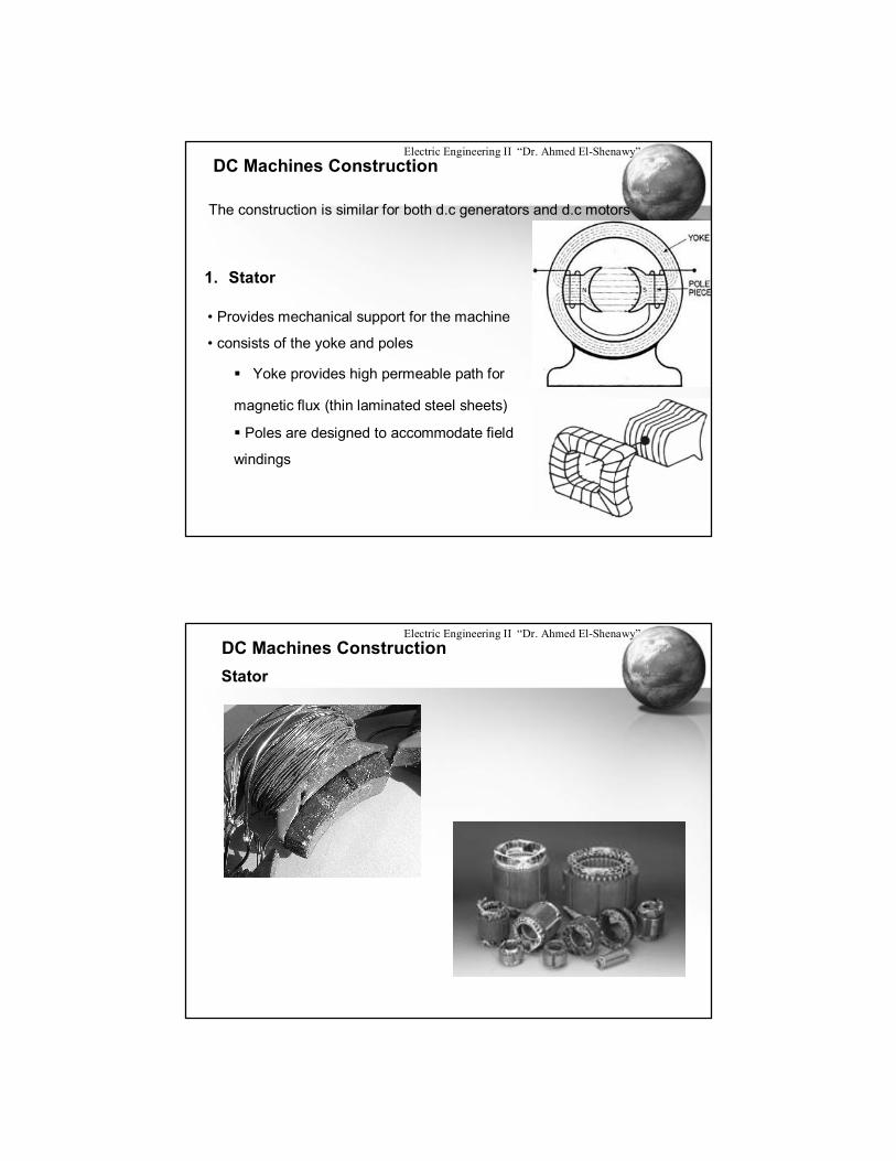
1. Stator
• Provides mechanical support for the machine
• consists of the yoke and poles
Yoke provides high permeable path for
magnetic flux (thin laminated steel sheets)
Poles are designed to accommodate field
windings
Electric Engineering II “Dr. Ahmed El-Shenawy”DC Machines ConstructionStator

Electric Engineering II “Dr. Ahmed El-Shenawy”DC Machines Construction
2. Field Winding
The coils are wound in such a way that the poles
alternate in their polarity
a)Shunt Field Winding: many turns of fine wire
b)Series Field Winding: few turns of heavy wire,
which are placed in series with armature winding
3. Armatureo The rotating part of the dc machine
o Has Circular Cross section and is made of thin
laminations that have axial slots to house the
armature coils
Electric Engineering II “Dr. Ahmed El-Shenawy”
DC Machines ConstructionArmature

Electric Engineering II “Dr. Ahmed El-Shenawy”
DC Machines ConstructionArmature
Electric Engineering II “Dr. Ahmed El-Shenawy”DC Machines ConstructionArmature

Electric Engineering II “Dr. Ahmed El-Shenawy”
DC Generators
Electric Equivalent Circuit of a DC Generator
E+-Ra
ia
RL
Field Winding
Field winding is responsible of setting up a flux
Electric Engineering II “Dr. Ahmed El-Shenawy”
Types of DC Generators
1. Permanent Magnet Generators
This type is characterized by being smaller, lighter and more efficient
compared to wound generators
Ia = IL
E+-Ra
Ia
RL
IL
φ Constant Flux
Electric Engineering II “Dr. Ahmed El-Shenawy”
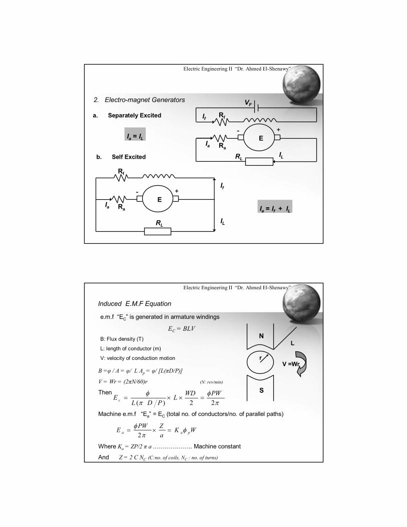
2. Electro-magnet Generators
E+-
RaIa
RLIL
RfIf
VF
a. Separately Excited
Ia = IL
b. Self Excited
Rf
E+-
RaIa
RLIL
If
Ia = If + IL
Electric Engineering II “Dr. Ahmed El-Shenawy”
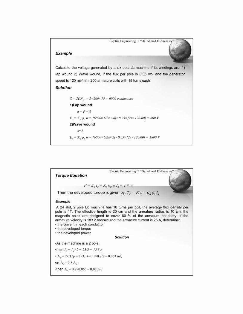
Induced E.M.F Equation
e.m.f “EC” is generated in armature windings
EC = BLVB: Flux density (T)
L: length of conductor (m)
V: velocity of conduction motion
N
S
L
rV =Wr
B =φ / A = φ/ L Ap = φ/ [L(πD/P)]
V = Wr = (2πN/60)r (N: rev/min)
Then
Machine e.m.f “Ea” = EC (total no. of conductors/no. of parallel paths)
Where Ka = ZP/2 π a ……………….. Machine constant
And Z = 2 C NC (C:no. of coils, NC : no. of turns)
WKaZPWE paa
2
22)(PWWDL
PDLE c
Electric Engineering II “Dr. Ahmed El-Shenawy”
Example
Calculate the voltage generated by a six pole dc machine if its windings are: 1)
lap wound 2) Wave wound, if the flux per pole is 0.05 wb. and the generator
speed is 120 rev/min, 200 armature coils with 15 turns each
Solution
Z = 2CNC = 2×200×15 = 6000 conductors
1)Lap wound
a = P = 6
Ea = Ka φp w = [6000×6/2π ×6]×0.05×[2π×120/60] = 600 V
2)Wave wound
a=2
Ea = Ka φp w = [6000×6/2π×2]×0.05×[2π×120/60] = 1800 V
Electric Engineering II “Dr. Ahmed El-Shenawy”Torque Equation
P = Ea Ia = Ka φp w Ia = T × w
Then the developed torque is given by: Td = P/w = Ka φp Ia
ExampleA 24 slot, 2 pole Dc machine has 18 turns per coil, the average flux density per
pole is 1T. The effective length is 20 cm and the armature radius is 10 cm. the magnetic poles are designed to cover 80 % of the armature periphery. If the armature velocity is 183.2 rad/sec and the armature current is 25 A, determine:• the current in each conductor• the developed torque• the developed power
Solution•As the machine is a 2 pole,
•then IC = Ia / 2 = 25/2 = 12.5 A
• Ap = 2πrL/p = 2×3.14×0.1×0.2/2 = 0.063 m2,
•as Ae = 0.8 Ap ,
•then Ae = 0.8×0.063 = 0.05 m2,
Electric Engineering II “Dr. Ahmed El-Shenawy”
•then φp = B Ae = 1×0.05 = 0.05 wb
•and Ka = (Zp/2πa) = (2×24×18)×2/2П×2 = 137.51
•Td = Ka Ia φp = 137.51×25×0.05 = 171.89 N.m
• Pd = Td ×w = 171.89×183.2 = 31490 W
Electric Engineering II “Dr. Ahmed El-Shenawy”
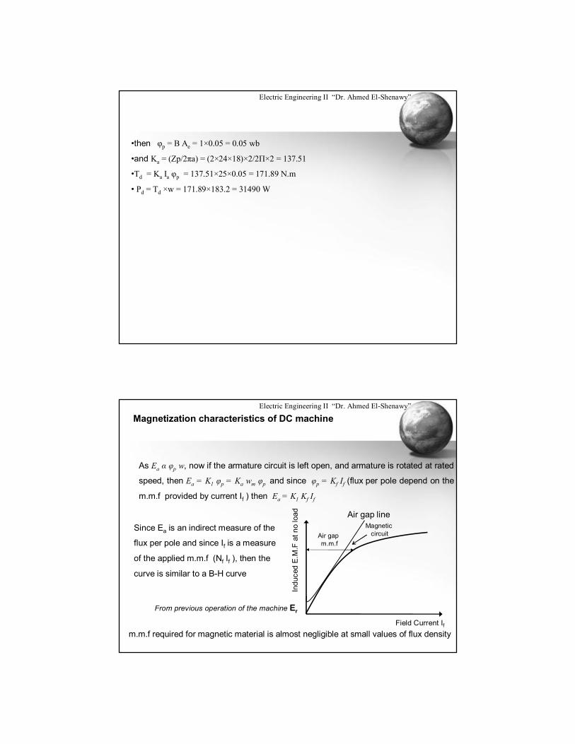
Magnetization characteristics of DC machine
As Ea α φp w, now if the armature circuit is left open, and armature is rotated at rated
speed, then Ea = K1 φp = Ka wm φp and since φp = Kf If (flux per pole depend on the
m.m.f provided by current If ) then Ea = K1 Kf If
Field Current If
Indu
ced
E.M
.F a
t no
load Air gap line
Magnetic circuitAir gap
m.m.f
From previous operation of the machine Er
Since Ea is an indirect measure of the
flux per pole and since If is a measure
of the applied m.m.f (Nf If ), then the
curve is similar to a B-H curve
m.m.f required for magnetic material is almost negligible at small values of flux density
Electric Engineering II “Dr. Ahmed El-Shenawy”
DC Machines
Armature Circuit Model
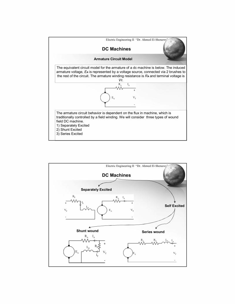
The equivalent circuit model for the armature of a dc machine is below. The induced armature voltage, EA is represented by a voltage source, connected via 2 brushes to the rest of the circuit. The armature winding resistance is RA and terminal voltage is
VT.
The armature circuit behavior is dependent on the flux in machine, which is traditionally controlled by a field winding. We will consider three types of wound field DC machine. 1) Separately Excited 2) Shunt Excited 3) Series Excited
Electric Engineering II “Dr. Ahmed El-Shenawy”
DC Machines
Separately Excited
Self Excited
Series woundShunt wound
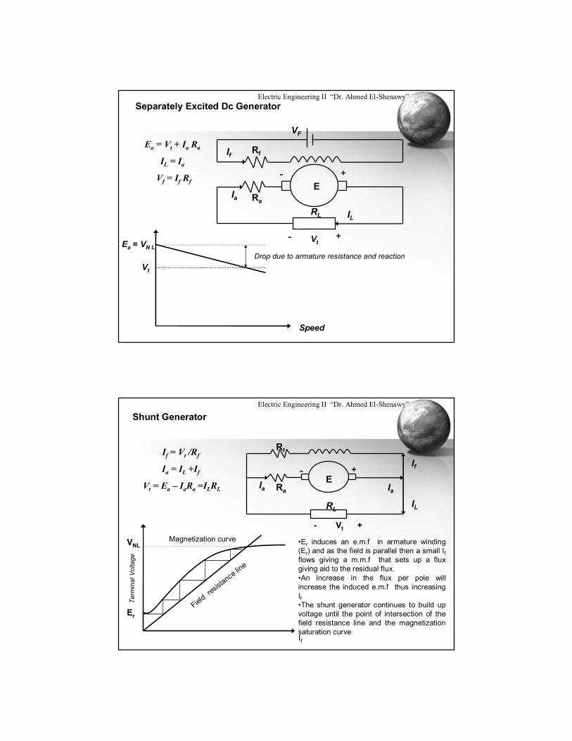
Electric Engineering II “Dr. Ahmed El-Shenawy”Separately Excited Dc Generator
Ea = Vt + Ia Ra
IL = Ia
Vf = If Rf E+-
RaIa
RL IL
RfIf
VF
Vt+-
Ea = VN L
Vt
Drop due to armature resistance and reaction
Speed
Electric Engineering II “Dr. Ahmed El-Shenawy”
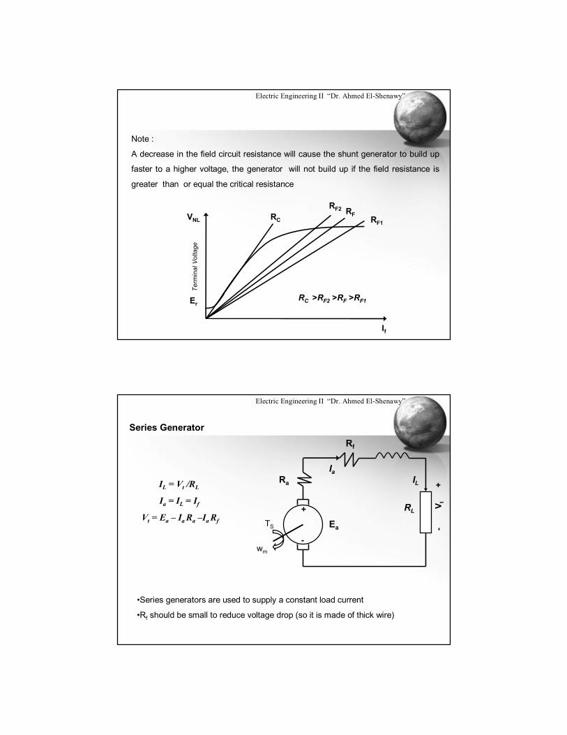
Shunt Generator
If = Vt /Rf
Ia = IL +If
Vt = Ea – IaRa =ILRLE
+-
RaIa
RLIL
Rf
If
Ia
- Vt +
Term
inal
Vol
tage
If
Field re
sistance lin
e
Magnetization curveVNL
Er
•Er induces an e.m.f in armature winding (Er) and as the field is parallel then a small Ifflows giving a m.m.f that sets up a flux giving aid to the residual flux.•An increase in the flux per pole will increase the induced e.m.f thus increasing If•The shunt generator continues to build up voltage until the point of intersection of the field resistance line and the magnetization saturation curve
Electric Engineering II “Dr. Ahmed El-Shenawy”
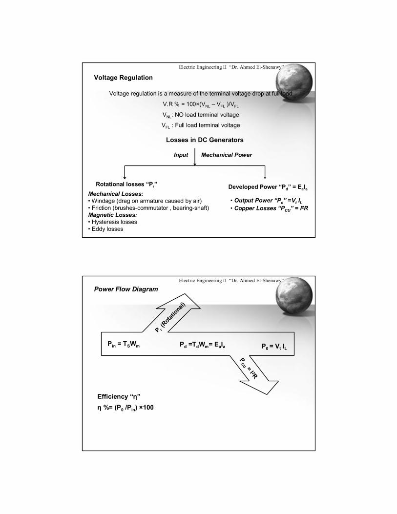
Note :
A decrease in the field circuit resistance will cause the shunt generator to build up
faster to a higher voltage, the generator will not build up if the field resistance is
greater than or equal the critical resistanceTe
rmin
al V
olta
ge
If
VNL
Er
RF1
RFRF2
RC
RC >RF2 >RF >RF1
Electric Engineering II “Dr. Ahmed El-Shenawy”
Series Generator
Ea
+
-
Ra
Ia
RL
Rf-
V t+
TS
wm
ILIL = Vt /RL
Ia = IL = If
Vt = Ea – Ia Ra –Ia Rf
•Series generators are used to supply a constant load current
•Rf should be small to reduce voltage drop (so it is made of thick wire)
Electric Engineering II “Dr. Ahmed El-Shenawy”
Voltage Regulation
Voltage regulation is a measure of the terminal voltage drop at full load
V.R % = 100×(VNL – VFL )/VFL
VNL: NO load terminal voltage
VFL : Full load terminal voltage
Losses in DC Generators
Input Mechanical Power
Rotational losses “Pr” Developed Power “Pd” = EaIaMechanical Losses:• Windage (drag on armature caused by air)• Friction (brushes-commutator , bearing-shaft)Magnetic Losses:• Hysteresis losses• Eddy losses
• Output Power “Po” =Vt IL• Copper Losses “PCU” = I2R
Electric Engineering II “Dr. Ahmed El-Shenawy”
Power Flow Diagram
Pin = TSWm
P r(R
otatio
nal)
Pd =TdWm= EaIa
PCU = I 2R
P0 = Vt IL
Efficiency “η”η %= (P0 /Pin) ×100
Electric Engineering II “Dr. Ahmed El-Shenawy”
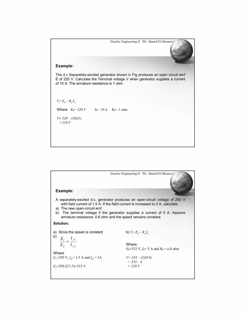
Example:
The d.c Separately-excited generator shown in Fig produces an open circuit emfE of 220 V. Calculate the Terminal voltage V when generator supplies a current of 10 A. The armature resistance is 1 ohm
Vt=Ea – Ra Ia
Where Ea= 220 V Ia= 10 A Ra= 1 ohm
Vt=220 – (10)(1)=210 V
Electric Engineering II “Dr. Ahmed El-Shenawy”
Example:
A separately-excited d.c. generator produces an open-circuit voltage of 250 V with field current of 1.5 A. If the field current is increased to 2 A, calculate
a) The new open-circuit emf.b) The terminal voltage if the generator supplies a current of 5 A. Assume
armature resistance- 0.8 ohm and the speed remains constant.
Solution:
a) Since the speed is constant b) Vt=Ea – Ra Iab)
Where E1=250 V, If1= 1.5 A and If2 = 2A
E2=250 (2/1.5)=333 V
Where Ea=333 V, Ia= 5 A and Ra = o.8 ohm
V= 333 – (5)(0.8)= 333 – 4= 329 V
2
1
2
1
f
f
II
EE
Electric Engineering II “Dr. Ahmed El-Shenawy”
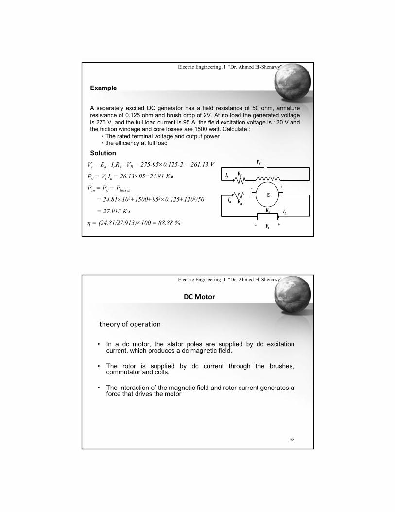
Example
A separately excited DC generator has a field resistance of 50 ohm, armature resistance of 0.125 ohm and brush drop of 2V. At no load the generated voltage is 275 V, and the full load current is 95 A. the field excitation voltage is 120 V and the friction windage and core losses are 1500 watt. Calculate :
• The rated terminal voltage and output power• the efficiency at full load
E
+-
RaIa
RL IL
RfIf
VF
Vt+-
Solution
Vt = Ea –IaRa –VB = 275-95×0.125-2 = 261.13 V
P0 = Vt Ia = 26.13×95=24.81 Kw
Pin = P0 + Plosses
= 24.81×10³+1500+952×0.125+1202/50
= 27.913 Kw
η = (24.81/27.913)×100 = 88.88 %
Electric Engineering II “Dr. Ahmed El-Shenawy”
32
DC Motor
• In a dc motor, the stator poles are supplied by dc excitation current, which produces a dc magnetic field.
• The rotor is supplied by dc current through the brushes, commutator and coils.
• The interaction of the magnetic field and rotor current generates a force that drives the motor
theory of operation
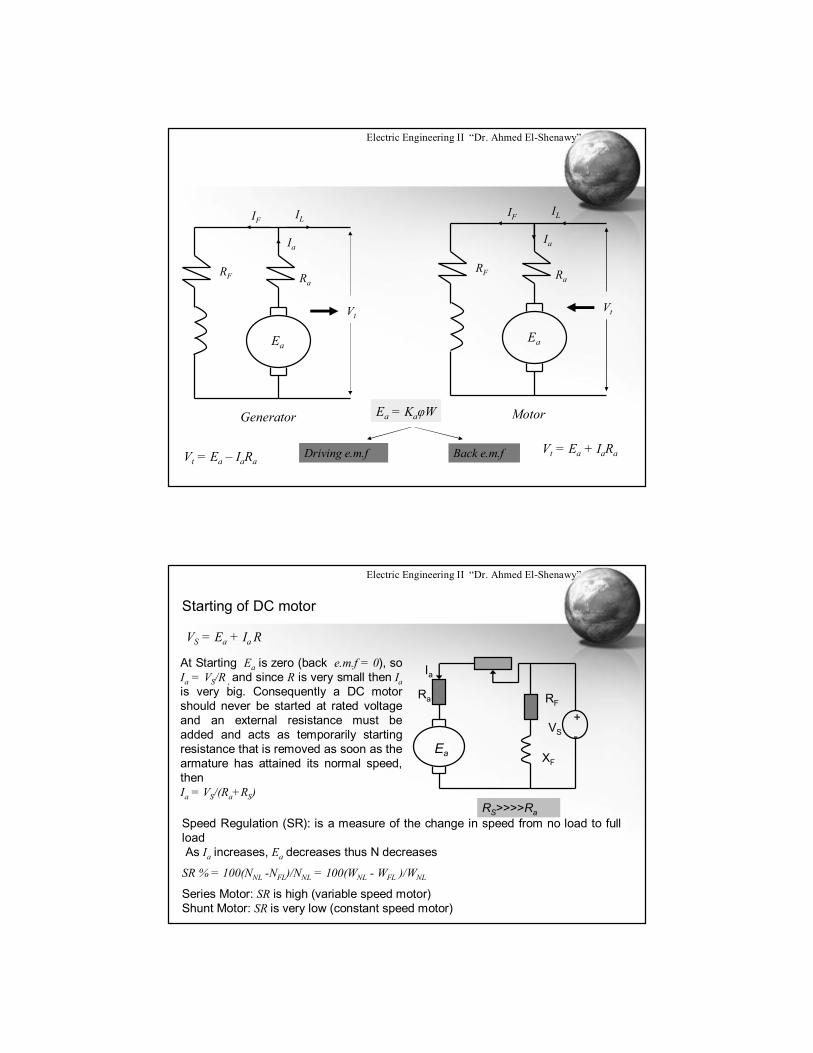
Electric Engineering II “Dr. Ahmed El-Shenawy”
Vt
Ia
RaRF
ILIF
Ea
Generator
Vt
Ia
RaRF
ILIF
Ea
Motor
Vt = Ea – IaRaVt = Ea + IaRa
Ea = KaφW
Driving e.m.f Back e.m.f
Electric Engineering II “Dr. Ahmed El-Shenawy”
Starting of DC motor
VS = Ea + Ia R
At Starting Ea is zero (back e.m.f = 0), so Ia = VS/R , and since R is very small then Iais very big. Consequently a DC motor should never be started at rated voltage and an external resistance must be added and acts as temporarily starting resistance that is removed as soon as the armature has attained its normal speed, thenIa = VS/(Ra+RS)
Ea
+-
Ra RF
XF
VS
Ia
RS>>>>RaSpeed Regulation (SR): is a measure of the change in speed from no load to full loadAs Ia increases, Ea decreases thus N decreases
SR % = 100(NNL -NFL)/NNL = 100(WNL - WFL )/WNL
Series Motor: SR is high (variable speed motor)Shunt Motor: SR is very low (constant speed motor)
Electric Engineering II “Dr. Ahmed El-Shenawy”
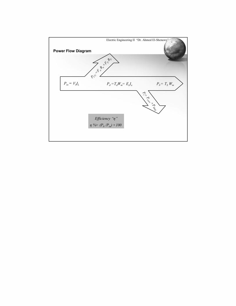
Power Flow Diagram
Pin = VSIL
P CU=I2 a
R a+I2 F
R F
Pd =TdWm= EaIa
Pr = P
core +PM
agP0 = TS Wm
Efficiency “η”
η %= (P0 /Pin) ×100