electric lighting design analysis tools
TRANSCRIPT

1
Ball State Architecture | ENVIRONMENTAL SYSTEMS 2 | Grondzik 1
ELECTRIC LIGHTINGDESIGN
ANALYSIS
Ball State Architecture | ENVIRONMENTAL SYSTEMS 2 | Grondzik 2
Reminder: Electric LightingDesign Analysis Tools
• Look-ups: pre-canned solutions provided by product manufacturers to speed adoption of solutions—in graphic or tabular format
• Correlations: product-generic methods—such as the zonal cavity method—applicable to many solutions
• First principles: employing basic physics relationships—such as the point-to-point method
• Computer simulations: to tap the data storage and number crunching capabilities of computers—often coupled with rendering routines
• Analog mock-ups: not common except for proof-of-concept demonstrations
2
Ball State Architecture | ENVIRONMENTAL SYSTEMS 2 | Grondzik 3
Illuminances of Concern
• Design illuminance = design criterion– The target or benchmark that defines “success”
• Initial illuminance = the illuminance experienced upon first operating a system (space and equipment are new)– LLF is set to 1.0 to estimate initial illuminance
• Maintained illuminance = the illuminance found in a space after some defined time (perhaps 2, 4, 5 years)– Condition that occurs when LLF assumes a real value– Maintained illuminance must equal or exceed design
illuminance in a successful system
Ball State Architecture | ENVIRONMENTAL SYSTEMS 2 | Grondzik 4
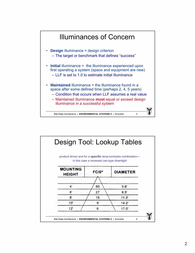
Design Tool: Lookup Tables
product driven and for a specific lamp-luminaire combination—
in this case a recessed can-type downlight
3
Ball State Architecture | ENVIRONMENTAL SYSTEMS 2 | Grondzik 5
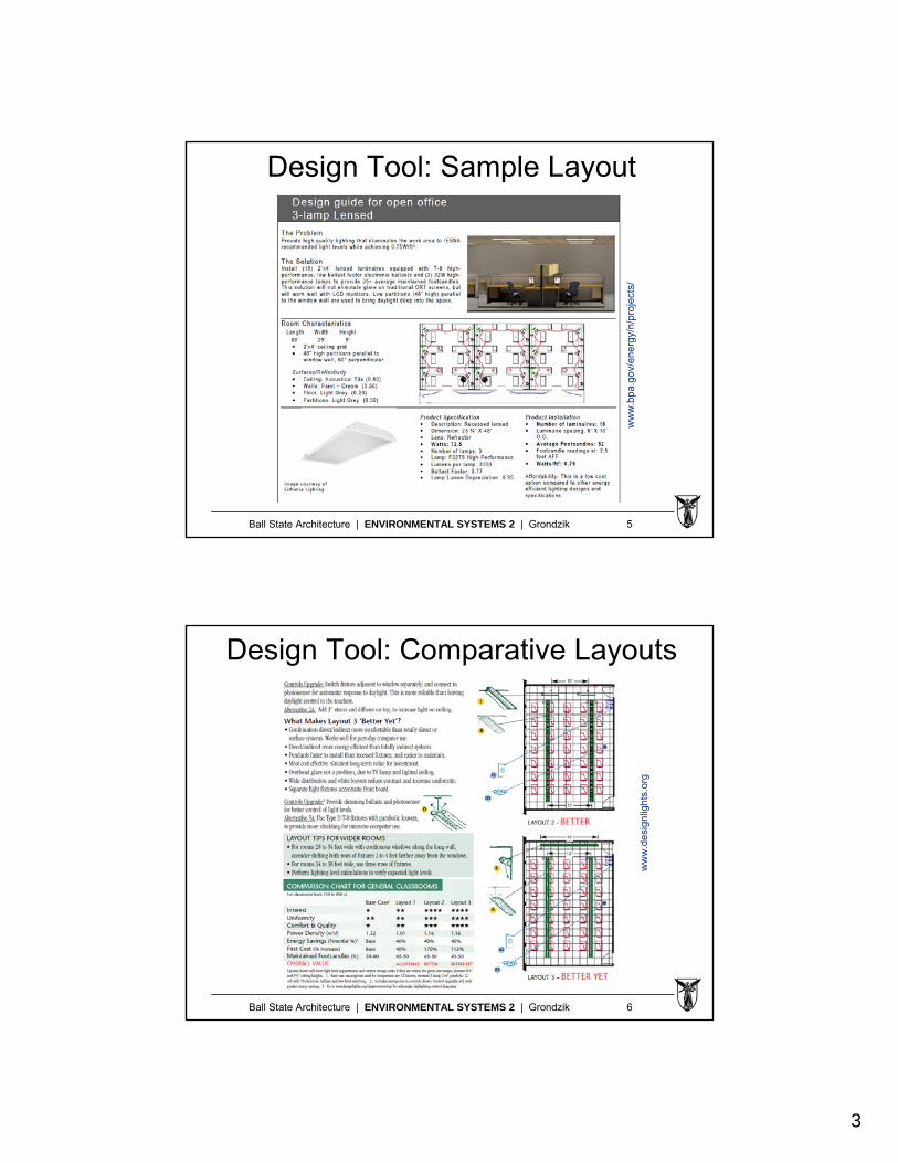
Design Tool: Sample Layout
ww
w.b
pa.g
ov/e
nerg
y/n/
proj
ects
/
Ball State Architecture | ENVIRONMENTAL SYSTEMS 2 | Grondzik 6
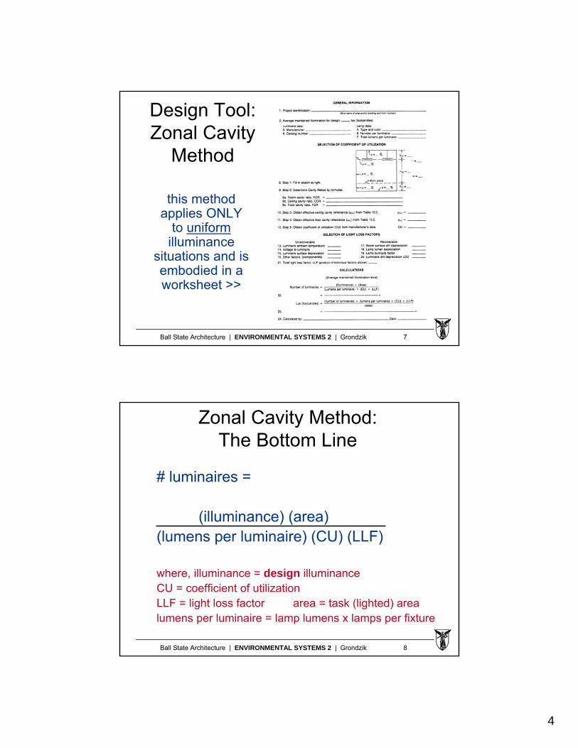
Design Tool: Comparative Layoutsw
ww
.des
ignl
ight
s.or
g
4
Ball State Architecture | ENVIRONMENTAL SYSTEMS 2 | Grondzik 7
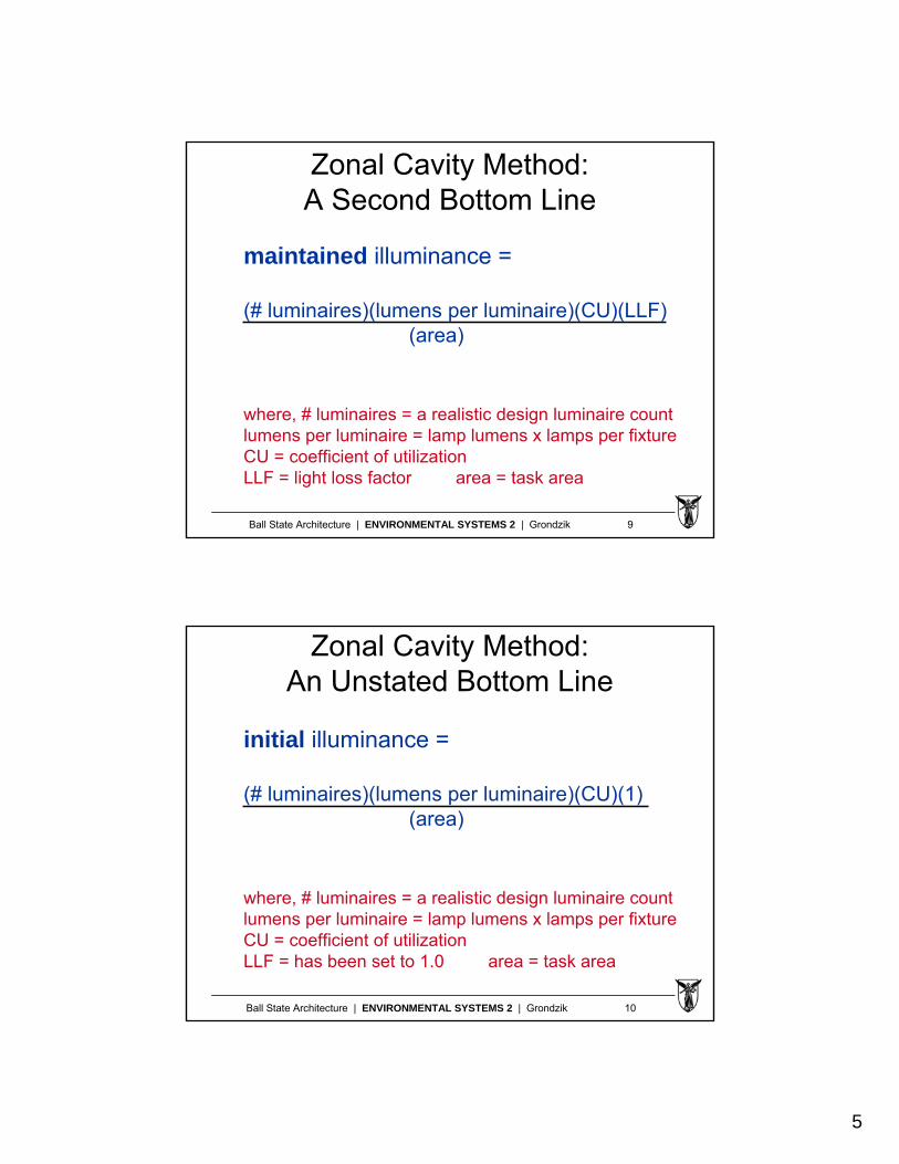
Design Tool:Zonal Cavity
Method
this method applies ONLY
to uniformilluminance
situations and is embodied in a worksheet >>
Ball State Architecture | ENVIRONMENTAL SYSTEMS 2 | Grondzik 8
Zonal Cavity Method:The Bottom Line
# luminaires =
(illuminance) (area)(lumens per luminaire) (CU) (LLF)
where, illuminance = design illuminanceCU = coefficient of utilizationLLF = light loss factor area = task (lighted) arealumens per luminaire = lamp lumens x lamps per fixture
5
Ball State Architecture | ENVIRONMENTAL SYSTEMS 2 | Grondzik 9
Zonal Cavity Method:A Second Bottom Line
maintained illuminance =
(# luminaires)(lumens per luminaire)(CU)(LLF)(area)
where, # luminaires = a realistic design luminaire countlumens per luminaire = lamp lumens x lamps per fixtureCU = coefficient of utilizationLLF = light loss factor area = task area
Ball State Architecture | ENVIRONMENTAL SYSTEMS 2 | Grondzik 10
Zonal Cavity Method:An Unstated Bottom Line
initial illuminance =
(# luminaires)(lumens per luminaire)(CU)(1)(area)
where, # luminaires = a realistic design luminaire countlumens per luminaire = lamp lumens x lamps per fixtureCU = coefficient of utilizationLLF = has been set to 1.0 area = task area
6
Ball State Architecture | ENVIRONMENTAL SYSTEMS 2 | Grondzik 11
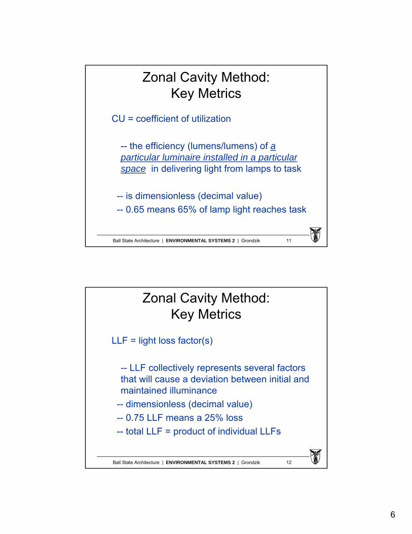
Zonal Cavity Method:Key Metrics
CU = coefficient of utilization
-- the efficiency (lumens/lumens) of a particular luminaire installed in a particular space in delivering light from lamps to task
-- is dimensionless (decimal value)
-- 0.65 means 65% of lamp light reaches task
Ball State Architecture | ENVIRONMENTAL SYSTEMS 2 | Grondzik 12
Zonal Cavity Method:Key Metrics
LLF = light loss factor(s)
-- LLF collectively represents several factors that will cause a deviation between initial and maintained illuminance
-- dimensionless (decimal value)
-- 0.75 LLF means a 25% loss
-- total LLF = product of individual LLFs
7
Ball State Architecture | ENVIRONMENTAL SYSTEMS 2 | Grondzik 13
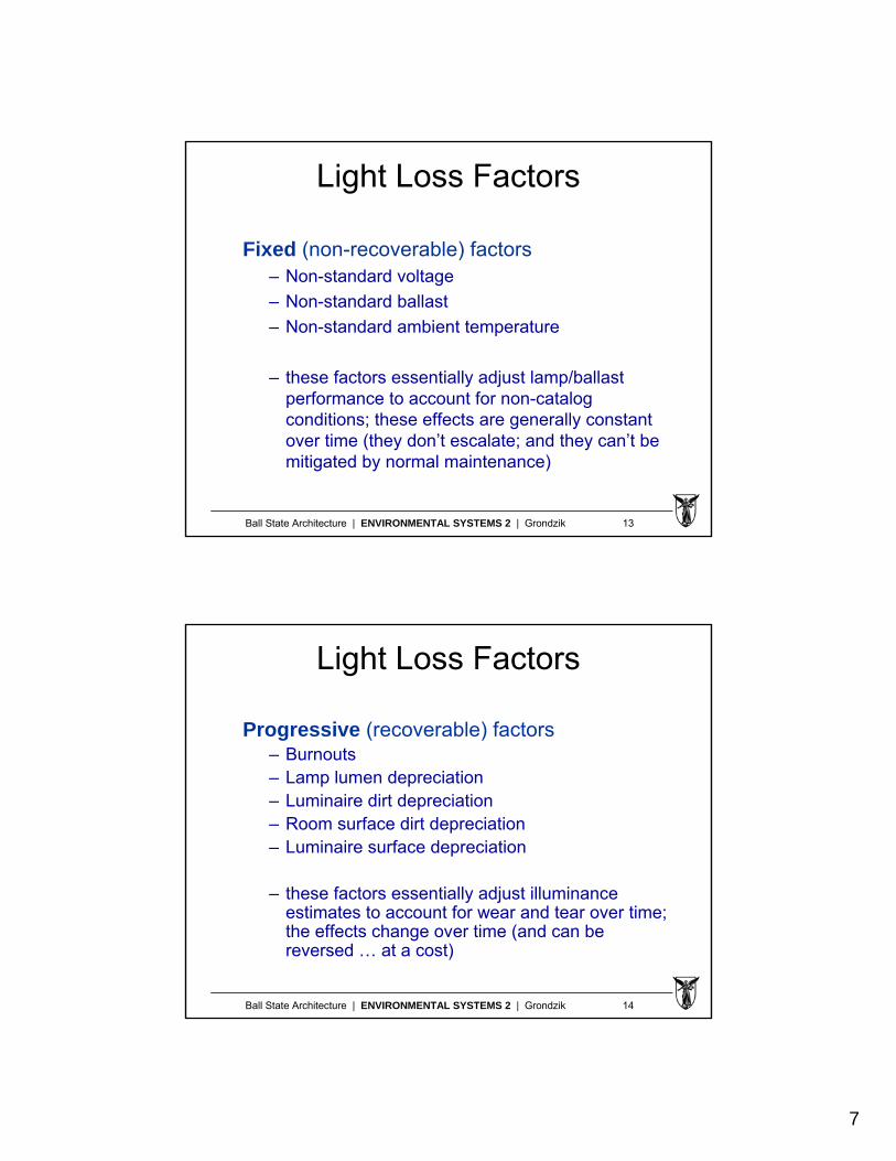
Light Loss Factors
Fixed (non-recoverable) factors– Non-standard voltage
– Non-standard ballast
– Non-standard ambient temperature
– these factors essentially adjust lamp/ballast performance to account for non-catalog conditions; these effects are generally constant over time (they don’t escalate; and they can’t be mitigated by normal maintenance)
Ball State Architecture | ENVIRONMENTAL SYSTEMS 2 | Grondzik 14
Light Loss Factors
Progressive (recoverable) factors– Burnouts– Lamp lumen depreciation– Luminaire dirt depreciation– Room surface dirt depreciation– Luminaire surface depreciation
– these factors essentially adjust illuminance estimates to account for wear and tear over time; the effects change over time (and can be reversed … at a cost)
8
Ball State Architecture | ENVIRONMENTAL SYSTEMS 2 | Grondzik 15
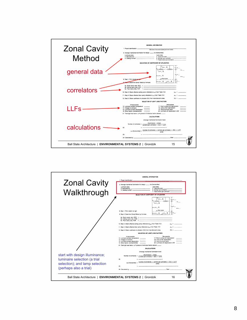
Zonal CavityMethod
general data
correlators
LLFs
calculations
Ball State Architecture | ENVIRONMENTAL SYSTEMS 2 | Grondzik 16
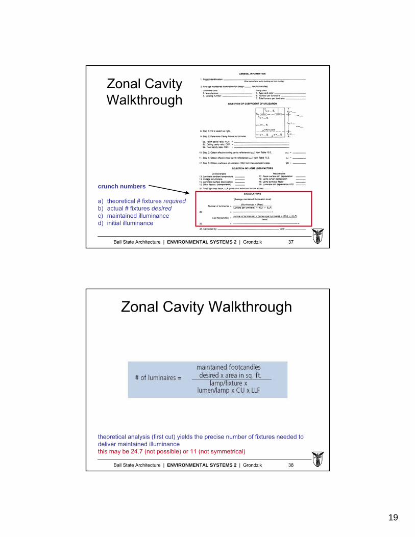
Zonal Cavity Walkthrough
start with design illuminance; luminaire selection (a trial selection); and lamp selection (perhaps also a trial)
9
Ball State Architecture | ENVIRONMENTAL SYSTEMS 2 | Grondzik 17
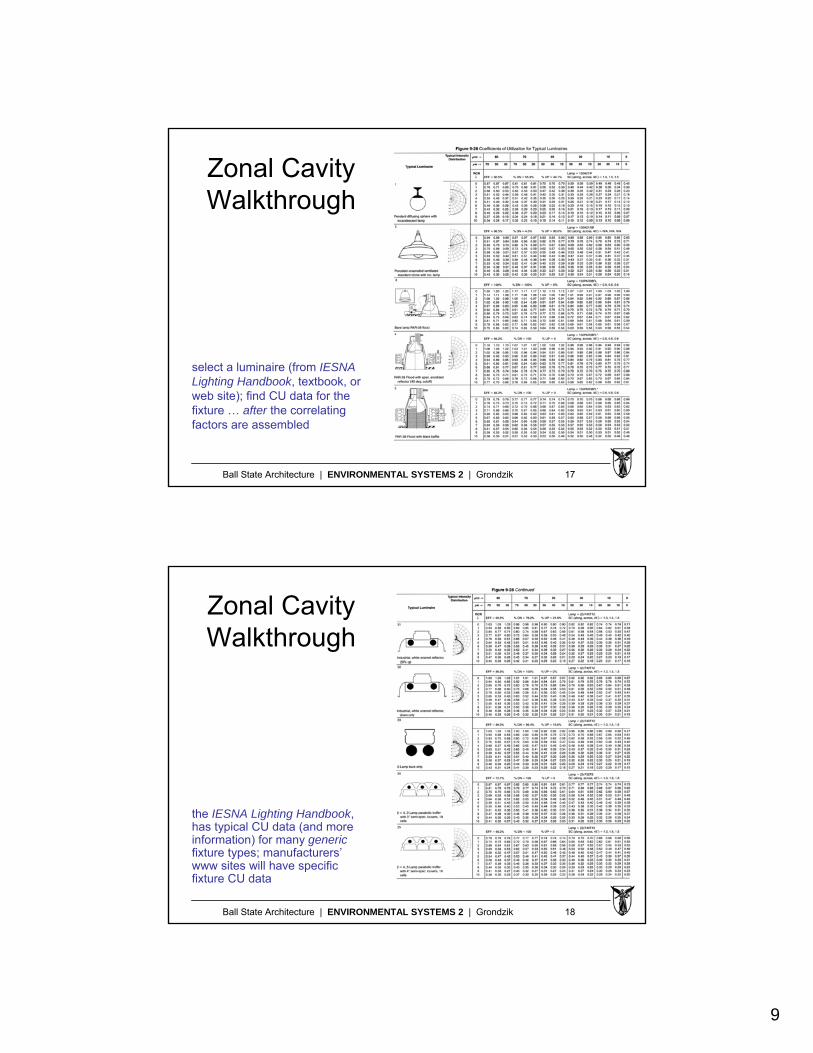
Zonal Cavity Walkthrough
select a luminaire (from IESNA Lighting Handbook, textbook, or web site); find CU data for the fixture … after the correlating factors are assembled
Ball State Architecture | ENVIRONMENTAL SYSTEMS 2 | Grondzik 18
Zonal Cavity Walkthrough
the IESNA Lighting Handbook, has typical CU data (and more information) for many genericfixture types; manufacturers’www sites will have specific fixture CU data
10
Ball State Architecture | ENVIRONMENTAL SYSTEMS 2 | Grondzik 19
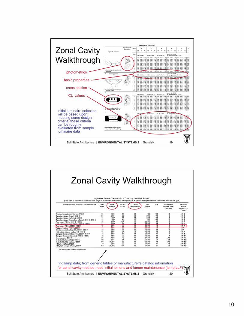
Zonal Cavity Walkthrough
initial luminaire selection will be based upon meeting some design criteria; these criteria can be roughly evaluated from sampleluminaire data
photometrics
basic properties
cross section
CU values
Ball State Architecture | ENVIRONMENTAL SYSTEMS 2 | Grondzik 20
Zonal Cavity Walkthrough
find lamp data; from generic tables or manufacturer’s catalog informationfor zonal cavity method need initial lumens and lumen maintenance (lamp LLF)
11
Ball State Architecture | ENVIRONMENTAL SYSTEMS 2 | Grondzik 21
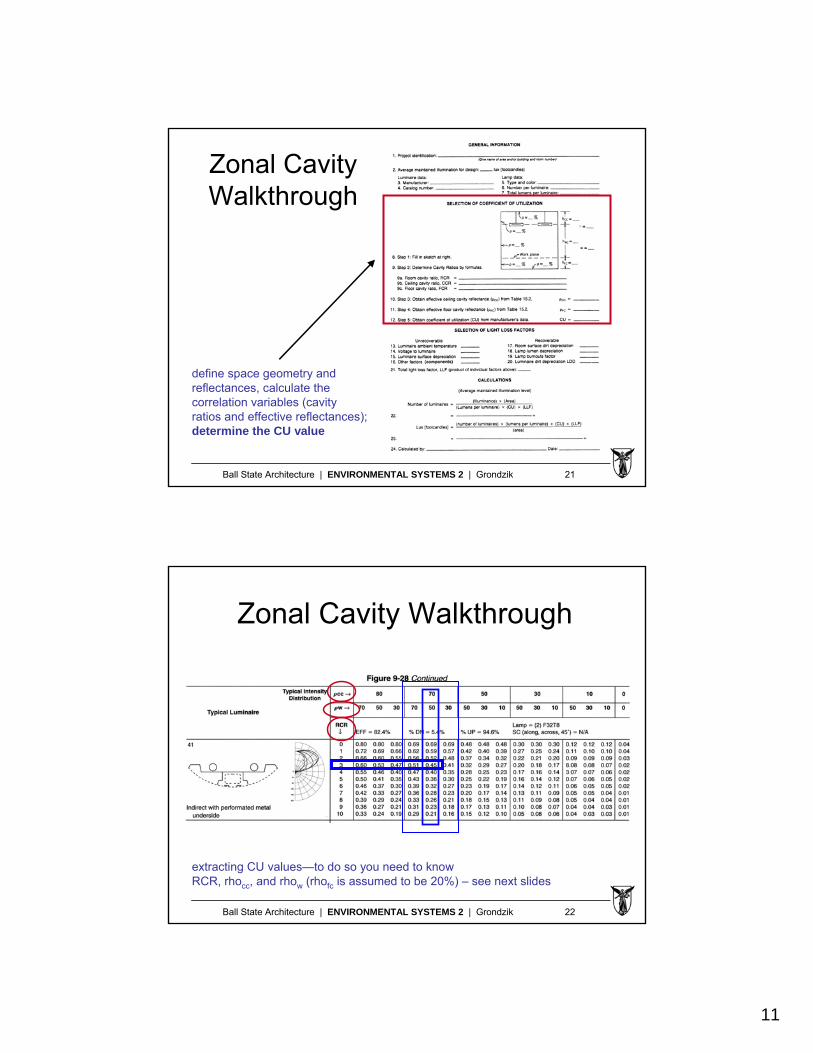
Zonal Cavity Walkthrough
define space geometry and reflectances, calculate thecorrelation variables (cavity ratios and effective reflectances); determine the CU value
Ball State Architecture | ENVIRONMENTAL SYSTEMS 2 | Grondzik 22
Zonal Cavity Walkthrough
extracting CU values—to do so you need to knowRCR, rhocc, and rhow (rhofc is assumed to be 20%) – see next slides

12
Ball State Architecture | ENVIRONMENTAL SYSTEMS 2 | Grondzik 23
Zonal Cavity Walkthrough
start with space dimensions (L, W, and H of three “cavities”)
Ball State Architecture | ENVIRONMENTAL SYSTEMS 2 | Grondzik 24
Zonal Cavity Walkthrough
calculate cavity ratios for three cavities using above equations (or look-up tables)a non-existent cavity has a ratio of “0” (h = 0)
13
Ball State Architecture | ENVIRONMENTAL SYSTEMS 2 | Grondzik 25
Zonal Cavity Walkthrough
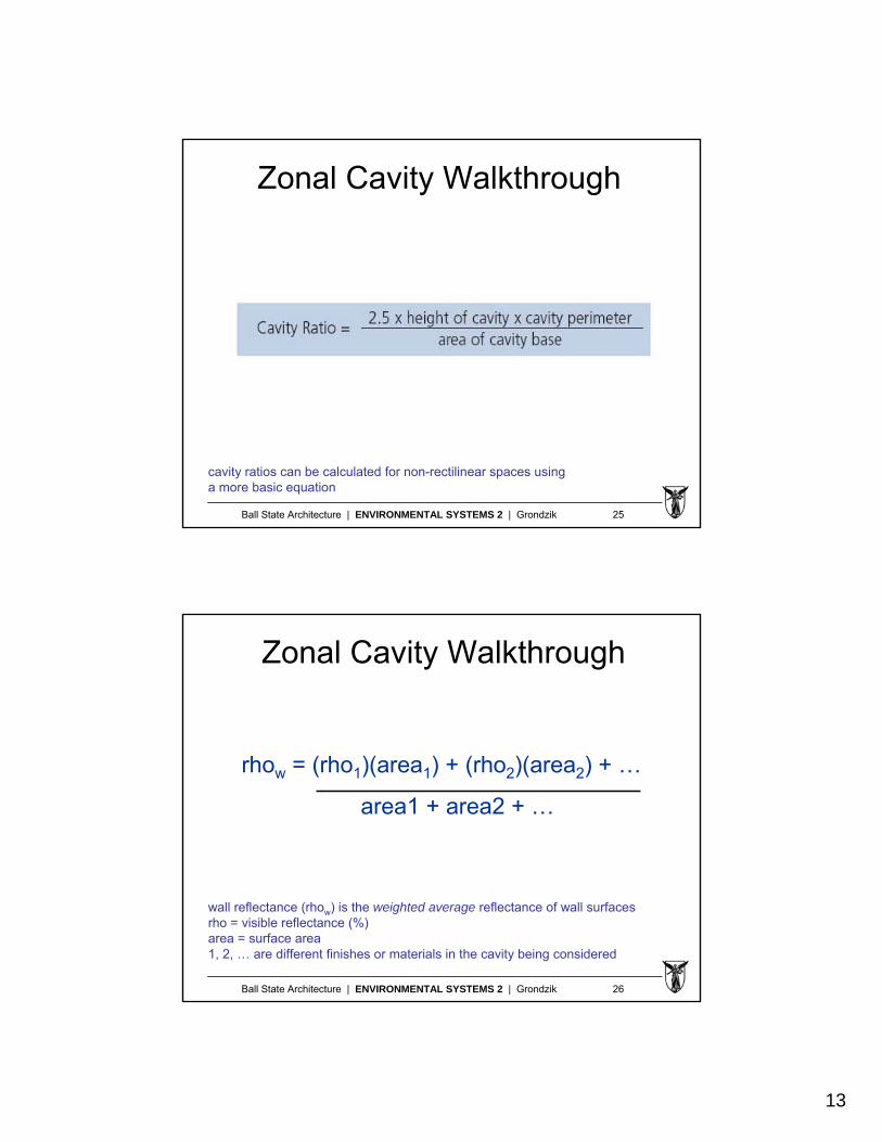
cavity ratios can be calculated for non-rectilinear spaces usinga more basic equation
Ball State Architecture | ENVIRONMENTAL SYSTEMS 2 | Grondzik 26
Zonal Cavity Walkthrough
wall reflectance (rhow) is the weighted average reflectance of wall surfacesrho = visible reflectance (%)area = surface area1, 2, … are different finishes or materials in the cavity being considered
rhow = (rho1)(area1) + (rho2)(area2) + …
area1 + area2 + …
14
Ball State Architecture | ENVIRONMENTAL SYSTEMS 2 | Grondzik 27
Zonal Cavity Walkthrough
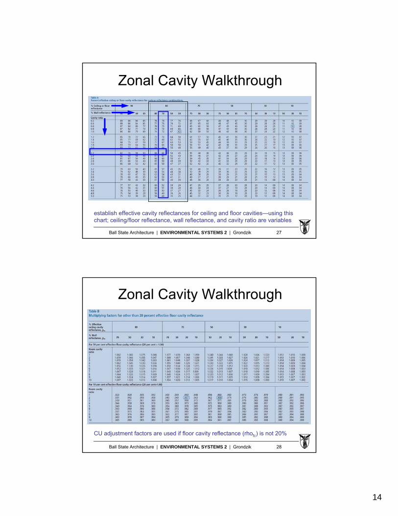
establish effective cavity reflectances for ceiling and floor cavities—using this chart; ceiling/floor reflectance, wall reflectance, and cavity ratio are variables
Ball State Architecture | ENVIRONMENTAL SYSTEMS 2 | Grondzik 28
Zonal Cavity Walkthrough
CU adjustment factors are used if floor cavity reflectance (rhofc) is not 20%
15
Ball State Architecture | ENVIRONMENTAL SYSTEMS 2 | Grondzik 29
Zonal Cavity Walkthrough
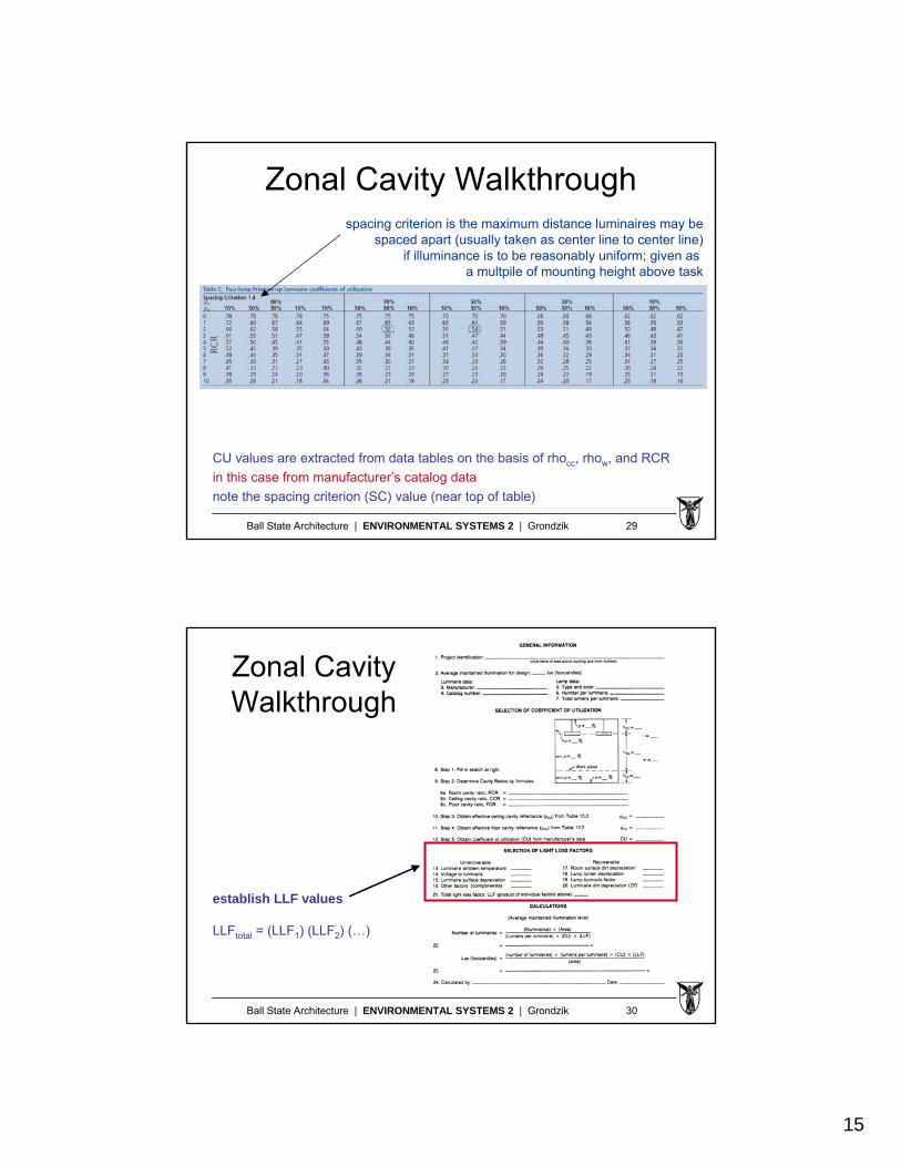
CU values are extracted from data tables on the basis of rhocc, rhow, and RCR
in this case from manufacturer’s catalog data
note the spacing criterion (SC) value (near top of table)
spacing criterion is the maximum distance luminaires may bespaced apart (usually taken as center line to center line)
if illuminance is to be reasonably uniform; given as a multpile of mounting height above task
Ball State Architecture | ENVIRONMENTAL SYSTEMS 2 | Grondzik 30
Zonal Cavity Walkthrough
establish LLF values
LLFtotal = (LLF1) (LLF2) (…)
16
Ball State Architecture | ENVIRONMENTAL SYSTEMS 2 | Grondzik 31
Zonal Cavity Walkthrough
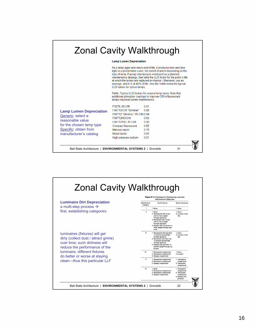
Lamp Lumen DepreciationGeneric: select a reasonable valuefor the chosen lamp typeSpecific: obtain from manufacturer’s catalog
Ball State Architecture | ENVIRONMENTAL SYSTEMS 2 | Grondzik 32
Zonal Cavity WalkthroughLuminaire Dirt Depreciationa multi-step process first, establishing categories
luminaires (fixtures) will getdirty (collect dust / attract grime)over time; such dirtiness willreduce the performance of the luminaire; different fixturesdo better or worse at stayingclean—thus this particular LLF
17
Ball State Architecture | ENVIRONMENTAL SYSTEMS 2 | Grondzik 33
Zonal Cavity Walkthrough
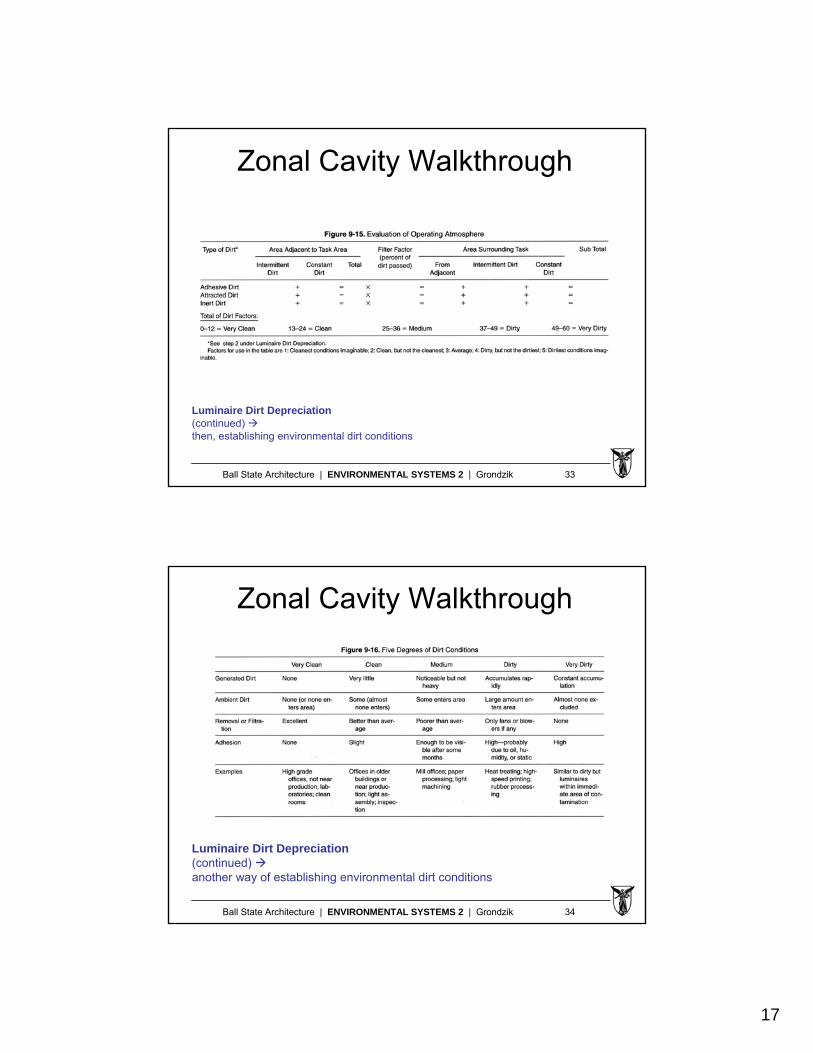
Luminaire Dirt Depreciation(continued) then, establishing environmental dirt conditions
Ball State Architecture | ENVIRONMENTAL SYSTEMS 2 | Grondzik 34
Zonal Cavity Walkthrough
Luminaire Dirt Depreciation(continued) another way of establishing environmental dirt conditions
18
Ball State Architecture | ENVIRONMENTAL SYSTEMS 2 | Grondzik 35
Zonal Cavity Walkthrough
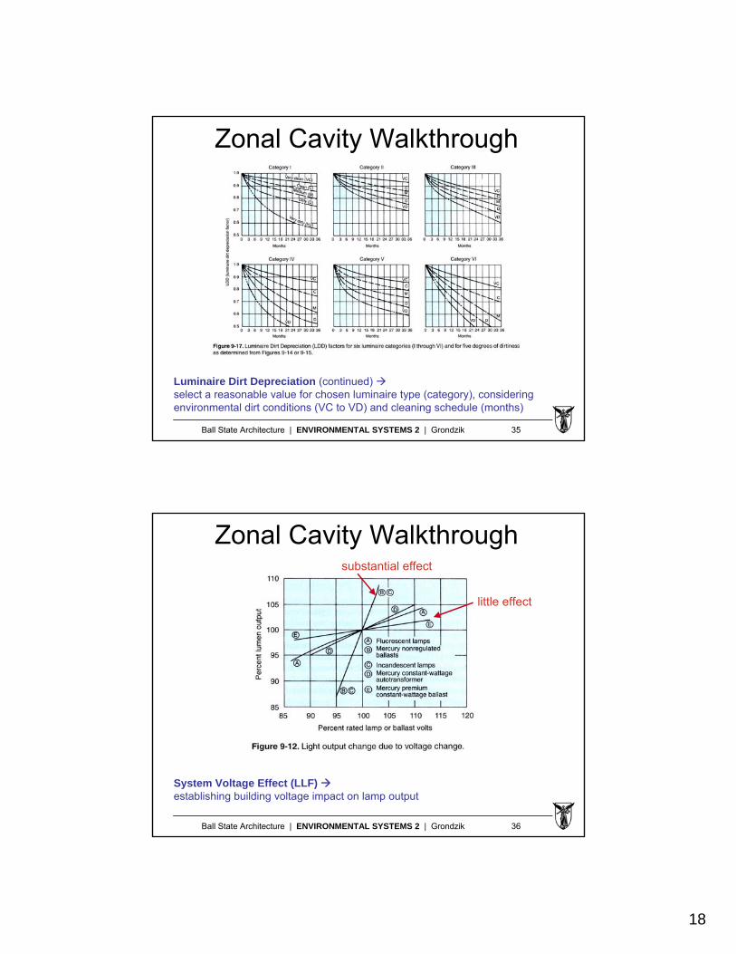
Luminaire Dirt Depreciation (continued) select a reasonable value for chosen luminaire type (category), considering environmental dirt conditions (VC to VD) and cleaning schedule (months)
Ball State Architecture | ENVIRONMENTAL SYSTEMS 2 | Grondzik 36
Zonal Cavity Walkthrough
System Voltage Effect (LLF) establishing building voltage impact on lamp output
substantial effect
little effect
19
Ball State Architecture | ENVIRONMENTAL SYSTEMS 2 | Grondzik 37
Zonal Cavity Walkthrough
crunch numbers
a) theoretical # fixtures requiredb) actual # fixtures desiredc) maintained illuminanced) initial illuminance
Ball State Architecture | ENVIRONMENTAL SYSTEMS 2 | Grondzik 38
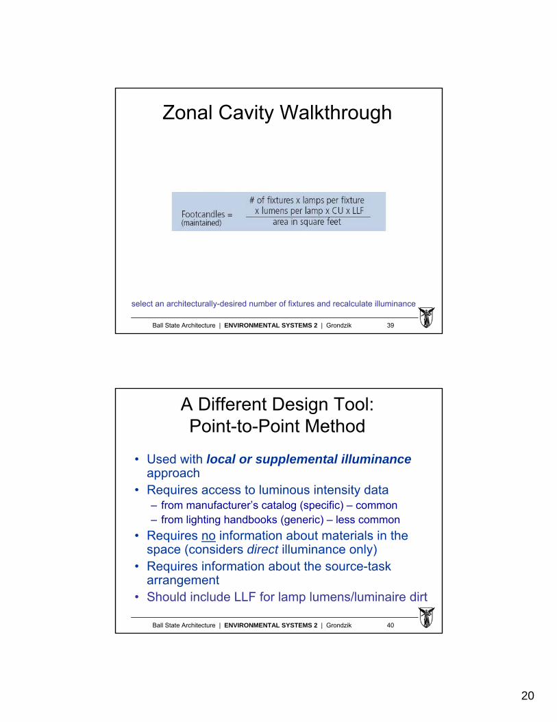
Zonal Cavity Walkthrough
theoretical analysis (first cut) yields the precise number of fixtures needed to deliver maintained illuminancethis may be 24.7 (not possible) or 11 (not symmetrical)
20
Ball State Architecture | ENVIRONMENTAL SYSTEMS 2 | Grondzik 39
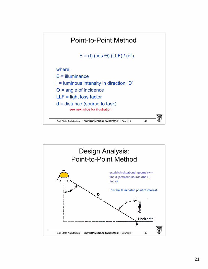
Zonal Cavity Walkthrough
select an architecturally-desired number of fixtures and recalculate illuminance
Ball State Architecture | ENVIRONMENTAL SYSTEMS 2 | Grondzik 40
A Different Design Tool:Point-to-Point Method
• Used with local or supplemental illuminanceapproach
• Requires access to luminous intensity data– from manufacturer’s catalog (specific) – common– from lighting handbooks (generic) – less common
• Requires no information about materials in the space (considers direct illuminance only)
• Requires information about the source-task arrangement
• Should include LLF for lamp lumens/luminaire dirt
21
Ball State Architecture | ENVIRONMENTAL SYSTEMS 2 | Grondzik 41
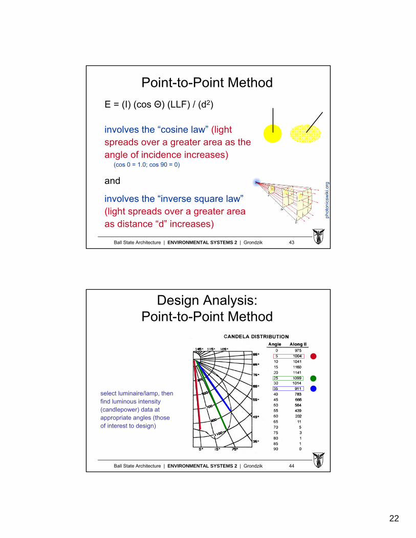
Point-to-Point Method
E = (I) (cos Θ) (LLF) / (d2)
where,
E = illuminance
I = luminous intensity in direction “D”
Θ = angle of incidence
LLF = light loss factor
d = distance (source to task)see next slide for illustration
Ball State Architecture | ENVIRONMENTAL SYSTEMS 2 | Grondzik 42
Design Analysis:Point-to-Point Method
establish situational geometry—
find d (between source and P)
find Θ
P is the illuminated point of interest
22
Ball State Architecture | ENVIRONMENTAL SYSTEMS 2 | Grondzik 43
Point-to-Point Method
E = (I) (cos Θ) (LLF) / (d2)
involves the “cosine law” (light spreads over a greater area as the angle of incidence increases)
(cos 0 = 1.0; cos 90 = 0)
and
involves the “inverse square law”(light spreads over a greater area as distance “d” increases)
phot
onic
swik
i.org
Ball State Architecture | ENVIRONMENTAL SYSTEMS 2 | Grondzik 44
Design Analysis:Point-to-Point Method
select luminaire/lamp, thenfind luminous intensity (candlepower) data at appropriate angles (thoseof interest to design)
23
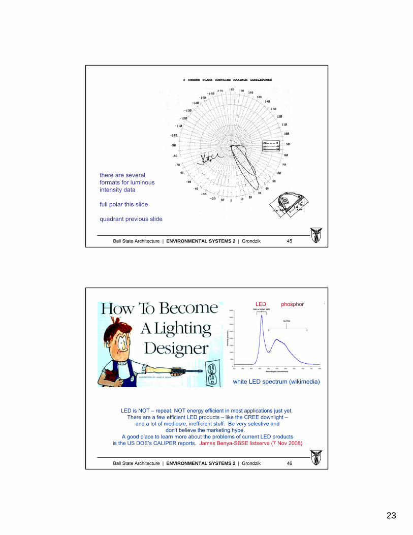
Ball State Architecture | ENVIRONMENTAL SYSTEMS 2 | Grondzik 45
there are several formats for luminous intensity data
full polar this slide
quadrant previous slide
Ball State Architecture | ENVIRONMENTAL SYSTEMS 2 | Grondzik 46
LED is NOT – repeat, NOT energy efficient in most applications just yet.There are a few efficient LED products – like the CREE downlight –
and a lot of mediocre, inefficient stuff. Be very selective and don’t believe the marketing hype.
A good place to learn more about the problems of current LED products is the US DOE’s CALIPER reports. James Benya-SBSE listserve (7 Nov 2008)
white LED spectrum (wikimedia)
LED phosphor