electric lock: 062.8262.-- installation and testing manual
TRANSCRIPT

Version: 3-12-2020
Electric lock: 062.8262.-- Installation and testing Manual for the installer & electrician.
Manually slide and electric lock + Preparations for potential conversion to motorized sliding

II&E2020_11 Hi-Finity electric lock: Installation and testing – Manual for the installer & electrician 2
Contents
1 Safety information ......................................................................... 3
2 Description of the Hi-Finity electric lock ............................................ 3
2.1 Parts list .............................................................................................................. 3 2.1.1 Choosing the right assembly .......................................................................... 4 2.1.2 Assembly accessories for electric lock ........................................................... 4 2.1.3 Additional/other finishing parts for pre-motorised element .............................. 7
2.1.4 Finishing parts for conversion to a motorised element .................................... 8
3 Assembly and installation ................................................................... 9 Legend 9
Assembly / installation order ............................................................................................ 9 3.1 Workshop preparations ....................................................................................... 9 3.1.1 Standard electric lock ..................................................................................... 9 3.1.2 Electric lock upgrade ready .......................................................................... 11
3.1.3 Electric lock upgrade to motorization ............................................................ 12 3.2 Onsite electric connections ............................................................................... 13 3.2.1 Power connection ......................................................................................... 13
3.2.2 Using Motor cable ......................................................................................... 13
3.2.3 Pre-wired Electric Cabinet ............................................................................ 13 3.3 Onsite completion mechanical installation ........................................................ 14 3.3.1 Assembly of the connection rod .................................................................... 14
3.3.2 Fine-tune the rod .......................................................................................... 14 3.3.3 Change operandi modus .............................................................................. 15
3.4 Testing .............................................................................................................. 15
4 LIABILITY AND GUARANTEE ............................................................ 16
5 DISMANTLING AND REMOVAL ......................................................... 16
6 FAQ 17
7 Technical specifications .................................................................... 18
7.1 Electric drawings ............................................................................................... 18
7.2 Connecting the alarm output ............................................................................. 21
© 2020 by Reynaers Aluminium. All rights reserved. Statement of Conditions In the interest of improving internal design, operational function, and/or reliability, Reynaers Aluminium reserves the right to make changes to the products described in this document without notice. Reynaers Aluminium does not assume any liability that may occur due to the use or application of the product(s) or circuit layout(s) described herein.
II&E2020_11 Hi-Finity electric lock: Installation and testing – Manual for the installer & electrician 3
1 Safety information
It is very important to have the Reynaers Hi-Finity Training before You start to order, construct or install. In this way, You are certified.
! The installation, connection and commissioning of electrical equipment must be carried out by a qualified electrician.
! The system contains approved parts and they should not be replaced just like that. The whole has been tested for optimal, high performance and guaranteed operation of the applications described.
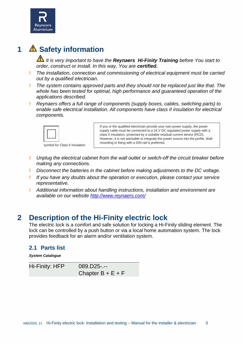
! Reynaers offers a full range of components (supply boxes, cables, switching parts) to enable safe electrical installation. All components have class II insulation for electrical components.
symbol for Class II insulation
! Unplug the electrical cabinet from the wall outlet or switch-off the circuit breaker before making any connections.
! Disconnect the batteries in the cabinet before making adjustments to the DC voltage.
! If you have any doubts about the operation or execution, please contact your service representative.
! Additional information about handling instructions, installation and environment are available on our website http://www.reynaers.com/
2 Description of the Hi-Finity electric lock The electric lock is a comfort and safe solution for locking a Hi-Finity sliding element. The lock can be controlled by a push button or via a local home automation system. The lock provides feedback for an alarm and/or ventilation system.
2.1 Parts list
System Catalogue
Hi-Finity: HFP 089.D25-.--
Chapter B + E + F
If you or the qualified electrician provide your own power supply, the power
supply cable must be connected to a 24 V DC regulated power supply with a
class II insulation, protected by a suitable residual current device (RCD).
However, it is not advisable to integrate the power source into the profile. Wall
mounting or fixing with a DIN rail is preferred.

II&E2020_11 Hi-Finity electric lock: Installation and testing – Manual for the installer & electrician 4
2.1.1 Choosing the right assembly
The electric lock can be assembled as standard electric lock or pre-assembled for an easy upgrade to a motorised Hi-Finity solution later-on.
! Both solutions use the same electric lock but different wires, millings and adapters in the system and connection to the vent. The wiring to the button and power can be re-used. No additional construction work needs to be done for the upgrade to a motorised solution.
Guidelines and decision matrices to help you select the right articles, quantities and millings can be found in the above-mentioned catalogue.
2.1.2 Assembly accessories for electric lock
! These items must be ordered individually and are not available in 1 set!
For a complete parts list of the element: see catalogue per possible configuration.
Mechanical parts
ELECTRIC LOCK FOR SLIDE MOTOR OR MANUAL Hi-Finity
(062.8262.--)
MOTOR LOCK COVER PLATE (062.8249.XX)
Or
RETROFIT MOTOR LOCK COVER PLATE
(062.8203.--)
For conversion 062.8228 or 062.8229 locks to 062.8262.--
CONNECTING ROD
(062.9551.--)
CONNECTING ROD - VENTILATION (150mm) (062.9550.C35)

II&E2020_11 Hi-Finity electric lock: Installation and testing – Manual for the installer & electrician 5
Electrical parts
R-SWITCH
MANUAL SWITCH INPUT
(061.8478.--)
ELECTRICAL CABINET 24V - 5.5A (062.8246.--)
OR
DIN-RAIL POWER SUPPLY 24VDC – 0.75AMPS (062.8623.--)
OR
BUILD-IN POWER SUPPLY 24VDC – 0.75AMPS (062.8624.--)
OR
DIN-RAIL POWER SUPPLY 24VDC – 1.75AMPS (062.8647.--)
OR
DIN-RAIL POWER SUPPLY 24VDC – 4.2AMPS (062.8595.--)
DIN-RAIL UNINTERRUPTED POWER SUPPLY 24VDC BATTERY BACKUP (062.8597.--)
Use diode (062.8596.--) if amount of coupled power supplies is more than 1
FOR REPLACEMENT BATTERY ONLY (OPTIONAL) (062.8608.--)

II&E2020_11 Hi-Finity electric lock: Installation and testing – Manual for the installer & electrician 6
Cables
POWER SUPPLY CABLE 10M
(062.8217.--)
POWER SUPPLY CABLE 3M
POWER - ALARM – BUTTON (3-in-1)
(062.8583.--)
or
POWER SUPPLY CABLE 10M
POWER - ALARM – BUTTON (3-in-1)
(062.8584.--)
Only to be used if 062.8217.-- and 062.8219.-- or
062.8222.-- or 062.8547 is not been selected
CABLE 10M FOR PUSH BUTTON
Installer sources push button
(062.8219.--)
or
CABLE 10M WITH PUSH BUTTON
(062.8222.--)
or
CABLE 10M WITH PUSH BUTTON + LED FEEDBACK
(062.8547.--)
BLUE LED WITH CABLE 0.5M
(062.8218.--)
Only to be used if cable 10m with push button + LED (062.8547.--) has not been selected

II&E2020_11 Hi-Finity electric lock: Installation and testing – Manual for the installer & electrician 7
2.1.3 Additional/other finishing parts for pre-motorised element
COVER PLATE RETURN PULLEY
(062.8257.XX)
COVER PLATE SLIDE MOTOR
(062.8258.XX)
CONNECTION ROD SYSTEM
(062.8259.--)
Do not use connecting rod
(062.9551.--)
POWER EXTENSION CABLE 5M
(062.8681.--)
+
PUSH BUTTON EXTENSION CABLE 5M
(062.8682.--)
LOCK CABLE FOR SLIDING WINDOW MOTOR 5M
Needs to be pre-installed - not possible afterwards
(062.8546.--)
EXTENSION CABLE ALARM CONTACT 5M
Optional, use only if 062.8583.-- or 062.8584.-- power
supply cable has been selected.
(062.8609.--)
DIN-RAIL POWER SUPPLY 24VDC – 4.2AMPS
(062.8595.--)
Not advised:
DIN-RAIL POWER SUPPLY 24VDC – 0.75AMPS
062.8623.-- can be used but needs to be replaced when
the conversion is made.

II&E2020_11 Hi-Finity electric lock: Installation and testing – Manual for the installer & electrician 8
2.1.4 Finishing parts for conversion to a motorised element
R-ADAPTER
(LOCK INPUT: SLIDE MOTOR + ELECTRIC LOCK)
(062.8296.--)
Replaces: 061.8478.--
SLIDING WINDOW MOTOR 50W
(062.8252.-- )
SLIDING WINDOW MOTOR DOCKING UNIT
(062.8254.--)
Replaces: 062.8681.-- + 062.8682.--
TIMING BELT 10M
(062.8549.--)
OR
TIMING BELT 30M
(062.8256.--)
SLIDING WINDOW MOTOR RETURN PULLEY
(062.8255.--)

II&E2020_11 Hi-Finity electric lock: Installation and testing – Manual for the installer & electrician 9
3 Assembly and installation Legend
title meaning
belt List item
! The element ... Note or Warning
▲1 Assembly step
062.8262.-- Set with art. n° or part of a set with art.n°
Safety Information
Assembly / installation order
The various subsystems were described in section 2.1. Assembly is done in the following order:
1 Workshop preparations Standard electric lock
Electric lock for possible upgrade to motorised element
Electric lock upgrade to motorization
2 Onsite electric connections Integrated power supply
Electric cabinet power supply
E-Cabinet
3 Onsite completion mechanical installation Connection rod
Fine-tune the rod
3.1 Workshop preparations
3.1.1 Standard electric lock
! The top profile millings (see catalogue) are close to the edge of the Hi-Finity moving glass pane.
▲1 Check the millings ▲2 Make all electrical connections
Use our bundled cable 062.8583.-- (3m) or 062.8584.-- (10m) if everything is installed in an electric cabinet or use separate cables when everything is locally around the sliding window installed.
Insert the R-Switch 061.8478.--
Connect all wires to the R-Switch box

II&E2020_11 Hi-Finity electric lock: Installation and testing – Manual for the installer & electrician 10
FIG: R-SWITCH BOX 061.8478.--
▲3 Install the lock and lock bracket
▲4 Protect the wires, electronics and electric devices for transport preventing damages.
! Electric devices are not water proof

II&E2020_11 Hi-Finity electric lock: Installation and testing – Manual for the installer & electrician 11
3.1.2 Electric lock upgrade ready
! The top profile millings (see catalogue) are >1meter from the edge of the Hi-Finity moving glass pane.
▲1 Check the millings
Milling for lock
Milling for slide motor
Milling for return pulley
Position of all millings as if for motorised
▲2 Make all electrical connections
Insert the R-Switch box 061.8478.--
The cables ((Power-, pushbutton- and alarmfeedback cable) or 6-wire cable) enter the profile at the position of the motor
Use the extension cable for the powercable 062.8681.-- and one for the pushbutton
062.8682.-- to extend to the position of the lock
The lock cable(no functionality during preparation period) and alarm feedback extension cable are already installed.
Positioning from the position of the motor to the position of the lock, through the correct chamber of the profile
Connect all wires to the R-Switch box
062.8681.-- + 062.8682.-- are the only cables that can be placed in the cavity where the future belt will be placed
▲3 Install the lock and lock bracket ▲4 Install finishing caps for motor and return pulley + millings need to be made already!!

II&E2020_11 Hi-Finity electric lock: Installation and testing – Manual for the installer & electrician 12
3.1.3 Electric lock upgrade to motorization
FIG: R-ADAPTER 062.8296.--
▲1 Install all new hardware
Motor 062.8252.--
Motor bracket and docking 062.8254.--
Return pulley 062.8255.--
Belt 062.8549.-- or 062.8256.-- and remove extension cables 062.8681.-- +
062.8682.--
▲2 Connect all electrical connections
Plug power supply cable in motordocking
Plug lock cable into motordocking
Replace R-Switch 061.8478.-- to R-adapter 062.8296.--
Connect the lock + Alarm extention cable + Lock cable
Install the lock
Place all covercaps
Verify Correct Power supply: 24VDC
Warnings regarding Installation of a motorized element The installation of this product will be part of a motorised window. Motorised windows involve a risk of crushing body parts and collision. For safety reasons only Reynaers Aluminium catalogue articles can be used to complete the system. The checklists for compliancy must be filled in and kept by the fabricator in the construction file together with the tender, the risk assessment, the instructions, the declaration of incorporation and the EC declaration of conformity. The motor shall be disconnected from its power source during maintenance and when replacing parts. Do not allow children to play with the appliance or its controls, including remotes.
CE-Marking This product complies with all of the relevant European guidelines and regulations. For safety regulations, Reynaers Aluminium NV declares that it’s conform with to the Machinery Directive 2006/42/EG. If applicable, the EU Declaration of Conformity can be found on www.reynaers.com. The completed window needs a certificate of conformity according to the Machinery Directive 2006/42/EG together with a user manual presented to the user and a CE label.

II&E2020_11 Hi-Finity electric lock: Installation and testing – Manual for the installer & electrician 13
3.2 Onsite electric connections
For detailed electric wiring diagrams please visit your customer portal on our website https://www.reynaers.com/en/reynaers-customer-portal-en > Access Control
3.2.1 Power connection
! The installation has to be done by a professional conform local regulations.
! Please install an uninterrupted power supply (UPS) with battery to prevent inconvenient behaviour during power outages.
Option 1: DIN-rail mounted power : see wiring diagram 401 in ANNEX
DIN-rail PSU 24VDC and In 0,75Amp : 062.8623.--
Optional DIN-rail battery backup UPS : 062.8597.-- Option 2: build in behind wall switch / profile : see wiring diagram 402 in ANNEX
Alternative PSU 24VDC and In 0,75Amp : 062.8624.—
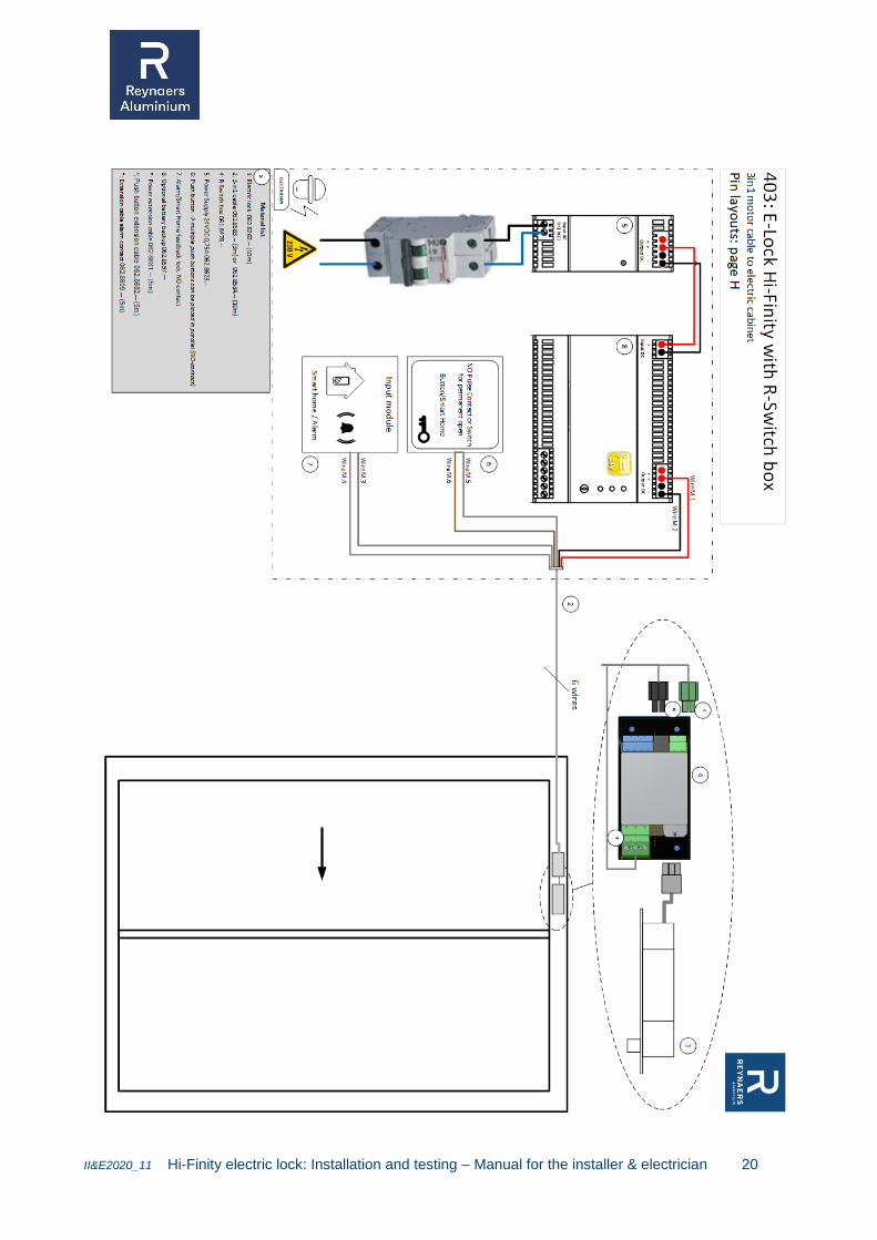
3.2.2 Using Motor cable
Bundle all required wires into 1 cable for ease of installation: See wiring diagram 403 in ANNEX
062.8583.-- Motor cable 3m 1
or 062.8584.-- Motor cable 10m 1
Fig.: motor cable with connector 1 for 24V-power, 2 for alarm feedback, 3 for push button
3.2.3 Pre-wired Electric Cabinet
Use pre-wired electric cabinet with wall socket for ease of installation and testing. The electric cabinet can connect up to 10 locks (when used exactly at the same time). 062.8246.-- see manual e-cabinet for connection details
II&E2020_11 Hi-Finity electric lock: Installation and testing – Manual for the installer & electrician 14
3.3 Onsite completion mechanical installation
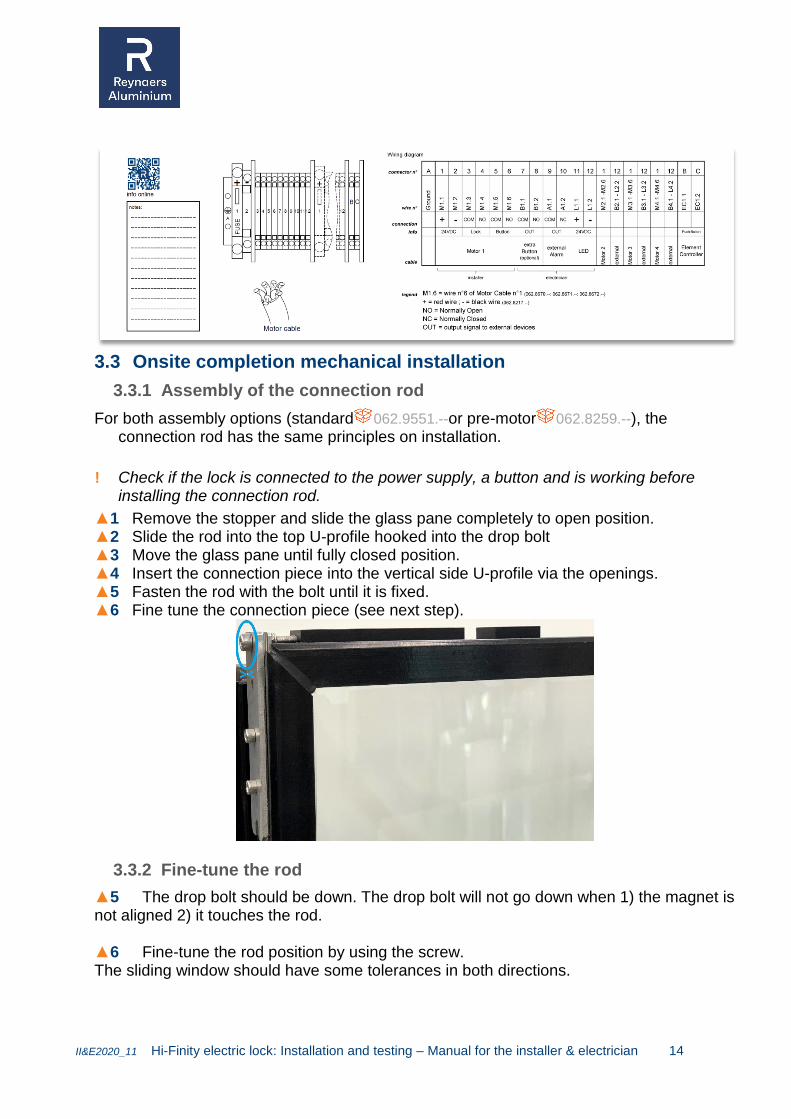
3.3.1 Assembly of the connection rod
For both assembly options (standard 062.9551.--or pre-motor 062.8259.--), the connection rod has the same principles on installation.
! Check if the lock is connected to the power supply, a button and is working before installing the connection rod.
▲1 Remove the stopper and slide the glass pane completely to open position. ▲2 Slide the rod into the top U-profile hooked into the drop bolt ▲3 Move the glass pane until fully closed position. ▲4 Insert the connection piece into the vertical side U-profile via the openings. ▲5 Fasten the rod with the bolt until it is fixed. ▲6 Fine tune the connection piece (see next step).
3.3.2 Fine-tune the rod
▲5 The drop bolt should be down. The drop bolt will not go down when 1) the magnet is not aligned 2) it touches the rod. ▲6 Fine-tune the rod position by using the screw. The sliding window should have some tolerances in both directions.

II&E2020_11 Hi-Finity electric lock: Installation and testing – Manual for the installer & electrician 15
3.3.3 Change operandi modus
! Warning: Do not lock yourself out. Check if a 2nd entrance into the building is available when changing the settings.
By default the lock will not drop down when the vent is in closed position : this is a safety modus for balconies where only 1 entrance to the building is possible. The drop bolt will go down when a pulse is triggered. LED feedback will show if this is done or not. By default the LED will be off when the vent is in locked position. The LED will be on when the vent is open. When the lock should lock, but is not yet locked because the magnet is not yet into place, the LED will blink. When it is required to lock each time the vent is back in closed position, follow the next procedure:
Take out the lock and R-Switch box
Unplug all wires on the R-Switch box
Unscrew the electronic board (PCB) from the housing.
Take out the PCB
Switch over the dip-switch1 in the centre of the board to “ON”.
Assemble the part again. When it is required to invert the functionality of the LED, follow the next procedure:
Take out the lock and R-Switch box
Unplug all wires on the R-Switch box
Unscrew the electronic board (PCB) from the housing.
Take out the PCB
Switch over the dip-switch2 in the centre of the board to “ON”.
Assemble the part again.
3.4 Testing
Now that the complete installation has been finished, perform a final Open/Close test, using the button.

II&E2020_11 Hi-Finity electric lock: Installation and testing – Manual for the installer & electrician 16
4 LIABILITY AND GUARANTEE This is a maintenance free system. Provided the lock and accessories were correctly installed and operated, the system are covered by a two-year guarantee. The guarantee ceases to apply if unauthorised modifications were made to the product. Further information on the guarantee can be found in the “Reynaers guarantee 20xx” document, available on the Reynaers website.
5 DISMANTLING AND REMOVAL Discarded materials are not worthless rubbish. Valuable raw materials can be recovered from them. Under Directive 2002/96/EC of the European Parliament and of the Council of 27 January 2003 on the sale, return and environmentally-friendly disposal of electrical and electronic equipment (WEEE) delivered after 13/08/2005, electrical and electronic equipment is recycled and may not be disposed of with household waste.

II&E2020_11 Hi-Finity electric lock: Installation and testing – Manual for the installer & electrician 17
6 FAQ By default, when is the LED on/off?
o If the window is locked: LED is off o If the window is unlocked: LED in on o If the lock should lock, but pen is still up: LED will blink o If dipswitch2 on R-Switch box is changed, LED functionality will be inverted
The lock is not unlocking
o Make sure 24VDC is supplied o If the window is closed, undo the connection rod to get to the lock o Check wiring diagrams and wire colors o Try different button on R-Switch box
The lock is not locking
o Check behaviour of the LED o Open the window and try holding a loose magnet to the lock for some seconds, is it
locking now? Yes:
Check the position of the lock, the pen should be on the side of the meeting section
Check the position of the magnet
Fine tune the connection rod No:
Try a different button on R-Switch box
Disconnect the power: o Pen of dropbolt lock stays up -> mechanical issue on lock o Pen of dropbolt lock falls down -> check wiring or R-Switch
box
The lock makes a tic-tic-tic noise? o Fine tune the lock! It touches the rod and cannot stay down.

II&E2020_11 Hi-Finity electric lock: Installation and testing – Manual for the installer & electrician 18
7 Technical specifications 7.1 Electric drawings

II&E2020_11 Hi-Finity electric lock: Installation and testing – Manual for the installer & electrician 19
II&E2020_11 Hi-Finity electric lock: Installation and testing – Manual for the installer & electrician 20

II&E2020_11 Hi-Finity electric lock: Installation and testing – Manual for the installer & electrician 21
7.2 Connecting the alarm output
The alarm output has 3 connections. By default Pin1 and Pin3 are connected and this will give a normal-closed circuit when the lock is closed and the window is closed, this means the pen of the dropbolt lock is down and the magnet is in the right position. Please remark that when there is no power on the R-Switch box, the contact between Pin1 and Pin3 will be open. More detailed information is available on http://www.reynaers.com/

II&E2020_11 Hi-Finity electric lock: Installation and testing – Manual for the installer & electrician 22
Electric lock 062.8262.--
Model Stainless steel bolt – fail secure
Input 24V – 0,75Amps
Voltage tolerance 22-30VDC
Protection class IP20
Dimensions Body 200 (L) x 32(W) x 46(D) (mm)
Dimensions Bolt 17(Throw) x 15.5(Diameter) (mm)
Shear force >1000kg
Operating temperature 0~90℃
Humidity 85%Rh max
R-Switch box 062.8344.--
Model R-Switch
Input 24VDC – 2Amp
Voltage tolerance ± 5%
Current protection Electronic overload shut-down
Protection class IP20
Setting positions Close on pulse (default) or close automatic
Operating temperature 0° to +50°C
Storage temperature −25° to 75°C
WEEE

II&E2020_11 Hi-Finity electric lock: Installation and testing – Manual for the installer & electrician 23
REYNAERS ALUMINIUM NV/SA
Oude Liersebaan 266 • B-2570 Duffel
t +32 15 30 85 00 • f +32 15 30 86 00
www.reynaers.com • [email protected]